1
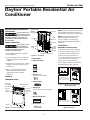
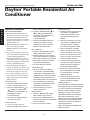
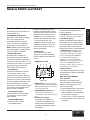
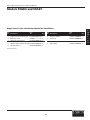
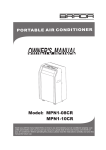
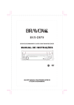
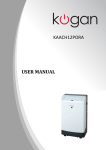
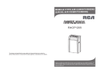
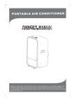
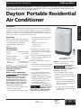
5EAK0 and 5EAK1
Operating Instructions & Parts Manual
PLEASE READ AND SAVE THESE INSTRUCTIONS. Read carefully before attempting to assemble, install, operate or maintain the product
described. Protect yourself and others by observing all safety information. Failure to comply with instructions could result in personal injury
and/or property damage! Retain instructions for future reference.
Dayton Portable Residential
Air Conditioner
®
Description
E
N
G
L
I
S
H
The Dayton compact heavy duty Portable Residential Air Conditioner equipped
with Remote Control containing batteries, produces low decibels while delivering
maximum cooling output. The unit features Even Air Distribution through auto
swing louvers. Ideal for spot cooling applications in small areas such as, small work
areas, homes, offices or IT equipment and server areas.
Unpacking
c. An area exposed to direct sunlight.
Handle carefully. Check the packing list
to account for all items. Visually inspect
for shipping damage. If damaged,
immediately file a claim with the
carrier.
d. An area where water is likely to
splash.
Specifications
AIR CONDITIONER
Models. . . . . . . . . . . . 5EAK0 and 5EAK1
Volts/Hz . . . . . . . . . . . . . . . . 115V, 60 Hz
BTU/Hour (5EAK0) . . . . . . . . . . . . . 8,100
BTU/Hour (5EAK1) . . . . . . . . . . . . 10,000
Operating Temp. Ranges:
Cool . . . . . . . . . . . . 17~32°C (62~92°F)
Dehumidify . . . . . . 13~32°C (54~92°F)
Dimension . . . . 33 1/16”x 1911/16”x 16 2/16”
General Safety Information
READ AND SAVE THESE
INSTRUCTIONS
MOBILE TYPE AIR CONDITIONER
This air conditioner
has no ventilator for
taking in fresh air from out of doors.
You must open doors or windows
frequently when you use gas or oil
heating appliances in the same room,
which consume a lot of oxygen from
the air. Otherwise, there is a risk of
suffocation in extreme cases.
1. Do not use in the following locations:
a. Next to source of fire.
b. An area where oil is likely to splash.
Form 5S5971
e. Near a bath, a shower or a
swimming pool.
f. In a green house.
2. Never insert your fingers or any
foreign objects into the air outlet.
Take special care to warn children of
these dangers.
3. Always store unit in upright/vertical
position, preventing damage to the
compressor system.
4. Be sure to unplug the unit before
cleaning.
5. The unit exhaust must never be located
near or in front of the socket outlet.
6. If the appliance is covered, there is a
risk of overheat.
7. Do not operate this unit if it has a
damaged cord or plug or if it is not
working properly, or has been
dropped or damaged in any manner.
If damaged take the unit to the
nearest authorized service facility
for examination, repair or
electrical/mechanical adjustment.
If the supply cord is
damaged, it must be
replaced by the manufacturer or its
service agent or a similarly qualified
person in order to avoid a hazard.
Printed in China
09663
0408/102/VCPVP
Figure 1 – Portable Residential
Air Conditioner with
Remote Control
NOTE: The following contents apply
only to countries in Europe.
E
S
P
A
Ñ
O
L
Do not dispose of
this product as
unsorted municipal waste. Collection of
such waste separately for special
treatment is necessary.
8. It is prohibited to dispose of this
appliance in domestic household
waste. For disposal, there are several
possibilities:
a. The municipality has established
collection systems, where electronic
waste may be disposed of free of
charge to the user.
b. As old products contain valuable
resources, they can be sold to scrap
metal dealers.
MID200
05/08
GGS #37
F
R
A
N
Ç
A
I
S
5EAK0 and 5EAK1
Dayton Operating Instructions and Parts Manual
Dayton Portable Residential Air
Conditioner
®
E
N
G
L
I
S
H
General Safety Information
(Continued)
Careless disposal of
waste in forests and
landscapes endangers your health when
hazardous substances leak into the
ground-water and find their way into
the food chain.
Upper Air Filter
(Behind
the grille)
Air intake
Air Outlet
Drain
Outlet
REMOTE CONTROLLER
Air intake
Be sure there are no
barriers between
the remote controller and the receiver
of indoor unit otherwise the air
conditioner will not work.
1. Keep the Remote Controller away
from all liquids.
2. Protect the Remote Controller from
high temperatures and exposure to
radiation.
Power cord
outlet
Lower
Air Filter
(Behind
the grille)
Bottom tray drain outlet
Figure 3 – Back View
ACCESSORIES
1. Remote Control
3. Keep the indoor receiver out of direct
sunlight or the Air Conditioner may
malfunction.
4. Keep controller away from EMI
(Electro-Magnetic Interference)
supplied by other household
appliances.
Features
NOTE: Check to see that all the accessories
are included in the package and refer to
the installation instructions for their usage.
NOTE: The rating data indicated on
the energy label is based on the
testing condition of installing the
unextended air exhaust duct without
adaptor A.
Installation
WINDOW KIT INSTALLATION
Your window kit has been designed
to fit most standard “Vertical” and
“Horizontal” window applications.
However, it may be necessary for
you to improvise/modify some aspects
of the installation procedures for
certain types of window. Please
refer to Figures 4 and 5 for minimum
and maximum window openings.
Horizontal
window
2. Battery (2 pc.)
(for remote controller)
Window Slider Kit
Minimum:67.5cm(2.22ft).
Maxmum:123cm(4.04ft).
COMPONENT PARTS
3. Exhaust Duct
Horizontal
Louver Blade
(manually)
Figure 4 – Minimum and Maximum
Window Openings
Operation Panel
Remote
signal
receptor
Carrying
Handle
(both side)
4. Adaptor A
(for temporary duct mounting)
Horizontal
window
5. Window Slider Kit
Window Slider Kit
Minimum:67.5cm(2.22ft).
Maxmum:123cm(4.04ft).
6. Foam Seal (3 pc.)
Caster
Figure 5 – Minimum and Maximum
Window Openings
Figure 2 – Front and Side View
2
Dayton Operating Instructions and Parts Manual
Models 5EAK0 and 5EAK1
Installation (Continued)
DUCT MOUNT INSTALLATION
Operation
NOTE: If the window opening is less
than the above mentioned minimum
length of the window slider kit, cut that
one with a hole in it short to fit the
window opening. Never cut out the
hole in window slider kit.
The exhaust hose and adaptor must
be installed or removed in accordance
with the usage mode.
AIR CONDITIONER
IMPORTANT: Install the mobile air
conditioner in a flat and spacious
location where the air outlets will not
be covered up. A minimum clearance of
12 inches shall be maintained from wall
or other obstacles. This air conditioner
should never be used in a laundry room.
The electrical 5-15P plug should always
be accessible after unit has been
positioned.
1. Install the window exhaust onto the
exhaust hose as shown in Fig.7. Refer
to the previous pages for window kit
installation.
2. Place the Exhaust hose over against
the air outlet opening hook and flat the
other end for quick installation.
COOL mode
Install
FAN or DEHUMIDIIFY mode Remove
Before starting this unit:
1. Select a suitable location, make sure
you have easy access to an electrical
outlet.
2. Install the flexible exhaust hose and
the adjustable window slider kit as
depicted in Figures 8 and 9.
Figure 8
Pu
30 c
m
(12”
)
cm
30
”)
(12
s
Figure 9
h in
NOTE: Step 2 is required only while
using the cooling mode.
Hook
Figure 6 – Minimum Wall Clearance
3. Plug the unit into a 115V~60Hz (refer
to the nameplate located on the right
side of the unit) grounded electrical
outlet. DO NOT USE A STANDARD
EXTENSION CORD. If it is necessary to
use an extension cord with this unit,
use an approved heavy duty air
conditioner extension cord ONLY.
4. Insert the power cord fixing strap into
the hole in the back of the unit, and
bundle up the excess cord.
Figure 7 – Attaching Adaptor and Duct
NOTE: The duct can be compressed or
extended moderately according to the
installation requirement, but it is
desirable to keep the duct length to a
minimum.
3
5. Make sure the water tank is correctly
positioned inside the cabinet
otherwise the unit will not operate.
6. Press the “POWER” button to turn on
the unit.
E
N
G
L
I
S
H
5EAK0 and 5EAK1
Dayton Operating Instructions and Parts Manual
Dayton Portable Residential Air
Conditioner
®
Operation (Continued)
E
N
G
L
I
S
H
ELECTRICAL REQUIREMENT
1. All wiring must comply with local
and national electrical codes and be
installed by a qualified electrician.
If you have any questions regarding
the following instructions, contact a
qualified electrician.
2. Check available power supply and
resolve any wiring problems
BEFORE installation and operation
of this unit.
3. For your safety and protection, this
unit is grounded through the power
cord plug when plugged into a
matching wall outlet. If you are not
sure whether the wall outlets in your
home are properly grounded, please
consult a qualified electrician.
4. The manufacturers nameplate is
located on the right side panel of the
unit and contains electrical and other
technical data specific to this unit.
5. To avoid the possibility of personal
injury, always disconnect the power
supply to the unit before installing
and/or servicing.
COOL operation
1. Press the "MODE" button until the
"COOL" indicator light comes on.
2. Press the ADJUST buttons " " or
" " to select your desired room
temperature. The temperature can
be set within a range of
O
O
O
O
17 C-30 C/62 F-88 F.
3. Press the "FAN SPEED" button to
choose the fan speed.
HEAT operation
(cooling only models without)
1. Press the "MODE" button until the
"HEAT" indicator light comes on.
2. Press the ADJUST buttons " " or
" " to select your desired room
temperature. The temperature can
be set within a range of
O
O
O
O
17 C-30 C/62 F-88 F.
3. Press the "FAN SPEED" button to
choose the fan speed. For some
models, the fan speed can not be
adjusted under HEAT mode.
TIMER operation
1. When the unit is on, first press the
Timer button, the TIMER OFF
indicator light illuminates. It indicates the Auto Stop program is
initiated.
2. When the unit is off, first press the
Timer button, the TIMER ON indicator light illuminates. It indicates
the Auto Start program is initiated.
3. Press or hold the UP or DOWN
DRY operation
button to change the Auto time by
1. Press the "MODE" button until the
0.5 hour increments, up to 10 hours,
"DRY" indicator light comes on.
then at 1 hour increments up to 24
2. Under this mode, you cannot select
hours. The control will count down
a fan speed or adjust the temperature.
the time remaining until start.
The fan motor operates at LOW speed.
4.
The selected time will register in 5
3. Keep windows and doors closed for
second and the system will automthe best dehumidifying effect.
atically revert back to display the
4. Do not put the duct to window.
previous temperature setting.
AUTO operation
5. Turning the unit ON or OFF at any
1. When you set the air conditioner
time or adjusting the timer setting
in AUTO mode, it will automatically
to 0.0 will cancel the Auto Start/
select cooling, heating(cooling only
Stop timed program.
models without), or fan only operation
6. When the malfunction (E1 or E2)
depending on what temperature you
occurs, the Auto Start/Stop timed
have selected and the room temperature.
program will also be cancelled.
2. The air conditioner will control room
SLEEP operation
temperature automatically round the
Press this button, the selected temperature
temperature point set by you.
will increase(cooling) or decrease(heating)
3. Under AUTO mode, you can not
O
O
by 1 C/2 F 30 minutes.The temperature
select the fan speed.
will then increase(cooling) or decrease
O
O
FAN operation
(heating) by another 1 C/2 F after an
1. Press the "MODE" button until the
additional 30 minutes. This new temper"FAN " indicator light comes on.
ature will be maintained for 7 hours
2. Press the "FAN SPEED" button to
before it returns to the originally selected
choose the fan speed. The temperature temperature. This ends the Sleep mode
cannot be adjusted.
and the unit will continue to operate as
3. Do not put the duct to window.
originally programmed.
NOTE: This feature is unavailabe under
FAN or DRY mode.
4
Dayton Operating Instructions and Parts Manual
Models 5EAK0 and 5EAK1
Operation (Continued)
6 UP(
CONTROL PANEL OF THE AIR
CONDITIONER
1 MODE select button
Selects the appropriate operating mode.
Each time you press the button, a mode
is selected in a sequence that goes from
AUTO, COOL, DRY, FAN and HEAT
(coolingonly models without). The mode
indicator light illuminates under the
different mode settings Fig.10.
2 TIMER button
Used to initiate the AUTO ON start time
and AUTO OFF stop time program, in
conjuction with the
&
buttons.
3 POWER button
Power switch on/off.
4 SLEEP button
Used to initiate the SLEEP operation.
5 FAN button
) and DOWN(
) button
P1- Bottom tray is full - Connect the
drain hose and drain the collected
water away. If error repeats, call
for service.
Used to adjust (increasing/decreasing)
temperature settings(1 C/2 F increments)
in a range of 17 C(62 F) to 30 C(88 F) or
the TIMER setting in a range of 0~24hrs..
8 ION button(optional)
NOTE: The control is capable of displaying
Press the ION button, the ion generator
is ener gized and will help to remove
pollen and impur ities from the air, and
trap them in the filter. Press it again to
stop the function.
temperature in degrees Fahrenheit or degrees
Celsius. To convert from one to the other, press
and hold the Up and Down buttons at the same
time, for 3 seconds.
7 LED Display
Shows the set temperature in " C" or
" F" and the Auto-timer settings.
While on DRY and FAN modes, it shows
the room temperature.
9 SWING button
(Applicable to the models with auto swing feature only)
When the operation is ON, press the
SWING button can stop the louver at
the desired angle. The louver swing up
to an angle of 6 for each press. Keep
pressing the button more than 2 seconds
can initiate the auto swing feature.
Error codes:
E1- Room temperature sensor errorUnplug the unit and plug it back in.
If error repeats, call for service.
E2- Evaporator temperature sensor errorUnplug the unit and plug it back in.
If error repeats, call for service.
E4- Display panel communication errorUnplug the unit and plug it back in.
If error repeats, call for service.
Control the fan speed. Press to select the
fan speed in four steps-LOW, MED, HI
and AUTO. The fan speed indicator light
illuminates under different fan settings
except AUTO speed. When select AUTO
fan speed, all the fan indicator lights
turn dark.
(The model has no
9
auto swing feature
withou t this button)
6
7
6
Remote signal receptor
(Some models have the
signal receptor on the
front panel )
8
SWING
ION
AUTO
COOL
HEAT
DRY
F
HI
C
MED
TIMER ON
SLEEP
MODE
FAN
TIMER OFF
FAN
1
3
2
Figure 10 – Control Panel
5
4
5
LOW
E
N
G
L
I
S
H
5EAK0 and 5EAK1
Dayton Operating Instructions and Parts Manual
Dayton Portable Residential Air
Conditioner
®
E
N
G
L
I
S
H
Operation (Continued)
CONTINUOUS DRAINAGE
1. During dehumidifying modes, remove
the drain plug from the back of the unit,
install the drain connector(5/8 universal
female mender) with 3/4 hose(locally
purchased). For the models without
drain connector, just attach the drain
hose to the hole. Place the open end of
the hose directly over the drain area in
your basement floor.
2. When the water level of the bottom
tray reaches a predetermined level,
the unit beeps 8 times, the digital
display area shows "P1". At this time
the air conditioning/dehumidification
process will immediately stop.
However, the fan motor will continue
to operate(this is normal). Carefully
move the unit to a drain location,
remove the bottom drain plug and let
the water drain away(Fig.13). Restart
the machine until the "P1" symbol
disappears. If the error repeats, call
for service.
sequence of the following:
AUTO
DRY
COOL
HEAT
FAN
NOTE: Heat mode is for Cooling & Heating models only.
SET TEMPERATURE( C)
FAN
HIGH
MED
LOW
AUTO
COOL
DRY
HEAT
TEMP
1
MODE
ON/OFF FAN SPEED
3
SWING
ECONOMY
TIMER ON
4
RESET LOCK
TIMER OFF
5
LED
DISPLAY
Remove the
drain plug
2
6
7
8
9
10
11
12
Figure 14 – Remote Control
Figure 11
Figure 13
REMOTE CONTROL
Continuous
drain hose
1.TEMP UP Button
Push this button to increase the indoor
o
o
temperature setting in 1 C(2 F) increments
o
o
to 30 C(88 F).
2.TEMP DOWN Button
Push this button to decrease the indoor
o
o
temperature setting in 1 C(2 F) increments
o
o
to 17 C(62 F).
Figure 12
3.MODE Button
Each time the button is pressed, the
operation mode is selected in the
TEMPERATURE CONVERSION CHART
°C 10 11 12 13 14 15 16 17 18 19 20 21 22 23 24 25 26 27 28 29 30 31 32 33
°F
48 50 52 54 56 58 60 62 64 66 68 70 72 74 76 78 80 82 84 86 88 90 92 94
6
4.SWING Button(on some models)
Used to stop or start louver movement
and set the desired up/down airflow direction.
5.RESET Button
Once the recessed RESET button is
pressed, all of the current settings will
be cancelled and the controller will
return to the initial settings.
6.ON/OFF Button
Operation starts when this button is
pressed and stops when the button
is pressed again.
7.FAN SPEED Button
Used to select the fan speed in four steps:
Auto Low Med High
8.TIMER ON Button
Press this button to activate the Auto-on
time setting. Each press will increase the
time setting in 30 minutes increments,
up to 10 hours, then at 1 hour increments
up to 24 hours. To cancel the Auto-on
Dayton Operating Instructions and Parts Manual
Models 5EAK0 and 5EAK1
Operation (Continued)
time setting, just press the button until
the time setting is 0.0.
9.ECONOMY(SLEEP) Button
Select this function during the sleeping
time. It can maintain the most
comfortable temperature and save
energy. This function is available on
COOL, HEAT or AUTO mode only .
NOTE: While the unit is running under
Energy-saving mode, it would be cancelled
if any other buttons are pressed.
10.TIMRT OFF Button
Press this button to activate the
Auto-off time setting. Each press will
increase the time setting in 30 minutes
increments, up to 10 hours,then at 1 hour
increments up to 24 hours. To cancel the
Auto-off time setting, just press the
button until the time setting is 0.0.
11.LOCK Button
Press this recessed button to lock all
current settings, and the remote
controller will not accept any operation
except that of the LOCK. Use the LOCK
mode when you want to prevent settings
from being changed accidentally. Press
the LOCK button again to cancel the
LOCK function. A lock symbol will appear
on the remote controller display when
the lock function is activated.
12.LED Display Button
Press this button to clear the display
on the indoor unit, press it again to
light the display .
13.FOLLOW ME Button
a. Press this button to initiate
FOLLOW ME function.
b. When the Follow Me function is
activated, the remote display is actual
temperature at its location. The remote
control will send this signal to the air
conditioner every 3 minutes interval
until press the Follow Me button again.
c. The Follow Me function is not
available under DRY and FAN mode.
d. Switch the operation mode or turn
off the unit will cancel the follow me
function automatically.
14.ION Button
When push this button, the ion
generator is energized and will help
to remove pollen and impurities from
the air.
Indicators on LCD
1
2
3
4
5
SET TEMPERATURE
6
TIMER ON OFF
4.ON/OFF display
This indicator will be displayed when
the unit is operating.
5. FAN Display: When the FAN button
is pushed, this signal indicator lights.
6.FAN SPEED display
Displays the selected fan speed: AUTO,
HIGH, MED and LOW. Nothing displays
when the fan speed is selected in AUTO
speed. When AUTO or DRY Mode is
selected, there will be no signals displayed.
7. TIMER Display: This display area
shows the settings of TIMER. That is,
if only the starting time of operation
is set, it will display the TIMER ON.
If only the turning off time of
operation is set, it will display the
TIMER OFF. If both operations are set,
it will show TIMER ON OFF which
indicates you have chosen to set both
the starting time and off time.
8.LOCK Indicator
LOCK display is displayed when pushing
the LOCK button. Push the LOCK button
to clear display.
How to use the buttons
8
7
Figure 15
1. MODE Display: Shows the current
operation modes–AUTO, COOL, DRY,
HEAT and FAN. HEAT only available
for heat pump model.
2. TRANSMISSION Indicator: This
indicator lights when remote
controller transmits signals to indoor
unit.
3.Temp./Timer display
The temperature setting (from
o
o
o
o
17 C(62 F) to 30 C(88 F)) or timer
setting (0~24h) will be displayed.
If FAN mode is selected, there will
be no display.
7
Auto operation
Ensure the unit is plugged in and
power is available. The OPERATION
indicator on the display panel of the
indoor unit illuminates.
1. Press the MODE button to select Auto.
2. Press the TEMP button to set the
desired temperature. The temperature
can be set within a range of
o
o
o
o
o
17 C(62 F)~ 30 C in 1 C(2 F) increments.
3. Press the ON/OFF button to start the air
conditioner.
E
N
G
L
I
S
H
5EAK0 and 5EAK1
Dayton Operating Instructions and Parts Manual
Dayton Portable Residential Air
Conditioner
®
Operation (Continued)
E
N
G
L
I
S
H
NOTE: In the AUTO mode, the air
conditioner can logically choose the
mode of COOL, FAN, HEAT and DRY by
sensing the difference between the
actual ambient room temperature and
the set temperature on the remote
controller.
In the Auto mode, you can not switch
the fan speed. It has already been
automatically controlled.
If the AUTO mode is not comfortable
for you, the desired mode can be
selected manually.
Cooling /Heating/Fan operation
Ensure the unit is plugged in and
power is available.
1. Press the MODE button to select
COOL, HEAT,(cooling & heating
models only) or FAN mode.
2. Press the TEMP button to set the
desired temperature. The temperature
can be set within a range of 17°C(62°F)
~ 30°C in 1°C(2°F) increments.
3. Press the FAN SPEED button to select
the fan speed in four steps- Auto, Low,
Med,or High.
4. Press the ON/OFF button to start the
air conditioner.
NOTE:In the FAN mode, the setting
temperature is not displayed in the remote
controller and you are not able to control
the room temperature either. In this case,
only step 1, 3 and 4 may be performed.
Dehumidifying operation
Ensure the unit is plugged in and
power is available. The OPERATION
indicator on the display panel of the
indoor unit illuminates.
1. Press the MODE button to select
DRY mode.
2. Press the TEMP button to set the
desired temperature. The temperature
can be set within a range of
17°C(62°F)~30°C in 1°C(2°F)increments.
3. Press the ON/OFF button to start
the air conditioner.
NOTE:In the Dehumidifying mode, you
can not switch the fan speed. It has
already been automatically controlled.
to reset the time to START the
operation.
b. Push the TIMER ON button again to
set desired unit start time.
c. After setting the TIMER ON ,there
will be a one-half second delay
before the remote controller
transmits the signal to the air
conditioner. Then, after
approximately another 2 seconds,
the signal “h” disappears and the
set temperature will reappear on
the digital display.
Swing operation(on some models)
Use the SWING button to adjust the
Up/Down airflow direction.
1. When press the button once and
2. To set the stopping time:
quickly, the air flow direction setting
a. Push the TIMER OFF button and the
feature of the louver is activated.
remote controller will show TIMER
The moving angle of the louver is
OFF, the last set time for the
°
6 for each press. Keep pressing the
stopping
operation and the signal
button to move the louver to the
“h” will be shown on the DIGITAL
desired position.
DISPLAY area. You are now ready
2. If keep pressing the SWING button
to reset the time of the STOP
without releasing for 2 more seconds,
operation.
the auto swing feature of the louver
b. Push the TIMER OFF button again
is activated. The horizontal louver
to set the time you want to stop
would swing up/down automatically.
the operation.
Press it again to stop.
c. After setting the TIMER OFF, there
NOTE: When the louver swing or move
will be a one-half second delay
to a position which would affect the cooling
before the remote controller
and heating effect of the air conditioner,
transmits the signal to the air
it would automatically change the swing/
conditioner. Then, after
moving direction.
approximately another 2 seconds,
Timer operation
the signal “h” disappears and the
TIMER ON button can set the auto-on
set temperature will reappear on
time of the unit. TIMER OFF button can
the digital display.
set the auto-off time of the unit.
ECONOMY(SLEEP) operation
1. To set the starting time:
When you press the ECONOMY button,
a. Push the TIMER ON button, then
the economic running function will be
the remote controller shows TIMER
activated,the set temperature will
ON, the last set time for the
increase(cooling) or decrease(heating)
starting operation and the signal
by 1°C(2°F) over the next 30 minutes
“h” will be shown on the DIGITAL
and by another 1°C(2°F) after an
DISPLAY area. You are now ready
8
Dayton Operating Instructions and Parts Manual
Models 5EAK0 and 5EAK1
Operation (Continued)
additional 30 minutes.This new
temperature will be maintained for
7 hours before it returns to the originally
selected temperature.(NOTE:On some
models, the set temperature will
increase (cooling) or decrease(heating)
by 1°C(2°F) per hour for 2 hours. This
new temperature will be maintained
for 5 hours ,then the unit is off.)
NOTE: The ECONOMY/SLEEP function
is only available under Cooling, Heating
and AUTO operation.
Be sure there are no
barriers between
the remote controller and the receiver
of indoor unit otherwise the air
conditioner will not work.
b. Removal
This unit has two filter. Grasp the
upper filter tab(Fig.16), pull the filter
out “ then up“. Remove the lower filter
by loosening the screw, taking down
the air inlet grille, then removing the
air filter as shown in Fig.17 & 18.
c. Cleaning
Wash the air filter by immersing it
gently in warm water(about 40°C/104°F)
with a neutral detergent. Rinse the filter
and dry it in a shady place.
d. Mounting
Insert the upper air filter from upward
after cleaning, attach the lower air filter
on the air inlet grille, then install the grille
by using the screw.
Air filter
(slide out)
Keep the Remote Controller away from
all liquids.
Protect the Remote Controller from
high temperatures and exposure to
radiation.
Figure 16
Keep the indoor receiver out of direct
sunlight or the Air Conditioner may
malfunction.
Keep controller away from EMI (ElectroMagnetic Interference) supplied by
other household appliances.
Maintenance
Be sure to unplug
unit before cleaning
or servicing.
DO NOT use gasoline, thinner or other
chemicals to clean the unit.
Remove the
screw and
take the air
inlet grille
down
2. Unit enclosure
Use a lint-free cloth soaked with neutral
detergent to clean the unit enclosure.
Finished by a dry clean cloth.
3. Unit idle for a long time
a. Remove the rubber plug at the back
of the unit and attach a hose to drain
outlet. Place the open end of the hose
directly over the drain area in your
basement floor.
b. Remove the plug from the bottom
drain outlet, all the water in the bottom
tray would drain out .
c. Keep the appliance running on FAN
mode for half a day in a warm room to
dry the appliance inside and prevent
mold forming.
d. Stop the appliance and unplug it,
wrapped the cord and bundle it with
the tape(Fig.19). Remove the batteries
from the remote controller.
e. Clean the air filter and reinstall it.
f. Unscrew the exhaust hose to the right
or left and pull out for uninstallation,
keep it safety, and cover the window(wall)
hole with the adaptor cap.
Power Cord
Band
Figure 17
NEVER wash the unit directly under a
tap or hose.
1. Air filter
a. Clean the air filter at least once every
two weeks to prevent inferior fan
operation because of dust.
Figure 19
Figure 18
Remove the air filter
out from the grille
9
Power Cord
E
N
G
L
I
S
H
5EAK0 and 5EAK1
Dayton Operating Instructions and Parts Manual
Dayton Portable Residential Air
Conditioner
®
Troubleshooting Chart
E
N
G
L
I
S
H
Symptom
Possible Cause(s)
Corrective Action
Unit does not start when
pressing power button
1. P1 appears in the display window
2. Room temperature is lower than the set
temperature (Cooling mode)
1. Drain the water in the bottom tray.
2. Reset the temperature
Not cool enough
1. The windows or doors in the room are not
closed
2. There are heat sources inside the room
3. Exhaust air duct is not connected or blocked
1. Make sure all the windows and doors
are closed
Power shuts off at heating
mode
4. Temperature setting is too high
5. Air filter is blocked by dust
The automatic over heat protection functioned.
When the temperature at the air outlet exceeds
70°C/158°F, the device will stop
2. Remove the heat sources if possible
3. Connect the duct and make sure it
can function properly
4. Decrease the set temperature
5. Clean the air filter
Switch on again after the unit has
cooled down
Noisy or vibrating
The ground is not level or not flat enough
Place the unit on flat, level ground if
possible
Gurgling sound
The sound comes from the flowing of the
refrigerant inside the air-conditioner
It is normal
10
5EAK0 and 5EAK1
Dayton Operating Instructions and Parts Manual
Notes
E
N
G
L
I
S
H
11
5EAK0 and 5EAK1
Dayton Operating Instructions and Parts Manual
For Repair Parts, call 1-800-323-0620
24 hours a day – 365 days a year
Please provide following information:
-Model number
-Serial number (if any)
-Part description and number as shown in parts list
2
E
N
G
L
I
S
H
Figure 20 – Repair Parts Illustration for Portable Residential Air Conditioner
12
Dayton Operating Instructions and Parts Manual
Models 5EAK0 and 5EAK1
Repair Parts List for Portable Residential Air Conditioner
Ref.
No. Description
1.
2.
3.
4.
5.
6.
Inlet Air Filter and Guard Set
Remote Control
Warm Air Exhaust Duct
Exhaust Duct Flange
Window Slider Adapter Flange
Window Slider 1
Part
No.
Qty.
HV201125080115G
HV2033 * * * * * * G
HV201125000013G
HV201125090064G
HV201125090063G
HV201125090001G
1
1
1
1
1
1
Ref.
No. Description
(∆) Not shown.
13
Part
No.
Qty.
7.
8.
Window Slider 2
Caster Set
HV201125090002G 1
HV202725000002G 4
∆
∆
Drain Hose Kit
Upper Plug
HV201125080131G 1
HV202725490003G 1
E
N
G
L
I
S
H
5EAK0 and 5EAK1
Dayton Operating Instructions and Parts Manual
Notes
E
N
G
L
I
S
H
14
5EAK0 and 5EAK1
Dayton Operating Instructions and Parts Manual
Notes
E
N
G
L
I
S
H
15
Dayton Operating Instructions and Parts Manual
5EAK0 and 5EAK1
Dayton Portable Residential Air
Conditioner
®
E
N
G
L
I
S
H
LIMITED WARRANTY
DAYTON ONE-YEAR LIMITED WARRANTY. DAYTON® PORTABLE RESIDENTIAL AIR CONDITIONER, MODELS COVERED IN
THIS MANUAL, ARE WARRANTED BY DAYTON ELECTRIC MFG. CO. (DAYTON) TO THE ORIGINAL USER AGAINST DEFECTS IN
WORKMANSHIP OR MATERIALS UNDER NORMAL USE FOR ONE YEAR AFTER DATE OF PURCHASE. ANY PART WHICH IS
DETERMINED TO BE DEFECTIVE IN MATERIAL OR WORKMANSHIP AND RETURNED TO AN AUTHORIZED SERVICE LOCATION,
AS DAYTON DESIGNATES, SHIPPING COSTS PREPAID, WILL BE, AS THE EXCLUSIVE REMEDY, REPAIRED OR REPLACED AT
DAYTON’S OPTION. FOR LIMITED WARRANTY CLAIM PROCEDURES, SEE “PROMPT DISPOSITION” BELOW. THIS LIMITED
WARRANTY GIVES PURCHASERS SPECIFIC LEGAL RIGHTS WHICH VARY FROM JURISDICTION TO JURISDICTION.
LIMITATION OF LIABILITY. TO THE EXTENT ALLOWABLE UNDER APPLICABLE LAW, DAYTON’S LIABILITY FOR CONSEQUENTIAL
AND INCIDENTAL DAMAGES IS EXPRESSLY DISCLAIMED. DAYTON’S LIABILITY IN ALL EVENTS IS LIMITED TO AND SHALL NOT
EXCEED THE PURCHASE PRICE PAID.
WARRANTY DISCLAIMER. A DILIGENT EFFORT HAS BEEN MADE TO PROVIDE PRODUCT INFORMATION AND ILLUSTRATE
THE PRODUCTS IN THIS LITERATURE ACCURATELY; HOWEVER, SUCH INFORMATION AND ILLUSTRATIONS ARE FOR THE SOLE
PURPOSE OF IDENTIFICATION, AND DO NOT EXPRESS OR IMPLY A WARRANTY THAT THE PRODUCTS ARE MERCHANTABLE,
OR FIT FOR A PARTICULAR PURPOSE, OR THAT THE PRODUCTS WILL NECESSARILY CONFORM TO THE ILLUSTRATIONS OR
DESCRIPTIONS. EXCEPT AS PROVIDED BELOW, NO WARRANTY OR AFFIRMATION OF FACT, EXPRESSED OR IMPLIED, OTHER
THAN AS STATED IN THE “LIMITED WARRANTY” ABOVE IS MADE OR AUTHORIZED BY DAYTON.
Technical Advice and Recommendations, Disclaimer. Notwithstanding any past practice or dealings or trade custom,
sales shall not include the furnishing of technical advice or assistance or system design. Dayton assumes no obligations or
liability on account of any unauthorized recommendations, opinions or advice as to the choice, installation or use of
products.
Product Suitability. Many jurisdictions have codes and regulations governing sales, construction, installation, and/or use of
products for certain purposes, which may vary from those in neighboring areas. While attempts are made to assure that
Dayton products comply with such codes, Dayton cannot guarantee compliance, and cannot be responsible for how the
product is installed or used. Before purchase and use of a product, review the product applications, and all applicable
national and local codes and regulations, and be sure that the product, installation, and use will comply with them.
Certain aspects of disclaimers are not applicable to consumer products; e.g., (a) some jurisdictions do not allow the exclusion
or limitation of incidental or consequential damages, so the above limitation or exclusion may not apply to you; (b) also,
some jurisdictions do not allow a limitation on how long an implied warranty lasts, consequently the above limitation may
not apply to you; and (c) by law, during the period of this Limited Warranty, any implied warranties of implied
merchantability or fitness for a particular purpose applicable to consumer products purchased by consumers, may not be
excluded or otherwise disclaimed.
Prompt Disposition. A good faith effort will be made for prompt correction or other adjustment with respect to any
product which proves to be defective within limited warranty. For any product believed to be defective within limited
warranty, first write or call dealer from whom the product was purchased. Dealer will give additional directions. If unable to
resolve satisfactorily, write to Dayton at address below, giving dealer’s name, address, date, and number of dealer’s invoice,
and describing the nature of the defect. Title and risk of loss pass to buyer on delivery to common carrier. If product was
damaged in transit to you, file claim with carrier.
Manufactured for Dayton Electric Mfg. Co., 5959 W. Howard St., Niles, Illinois 60714-4014 U.S.A.
Manufactured for Dayton Electric Mfg. Co.
Niles, Illinois 60714 U.S.A.