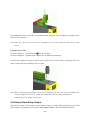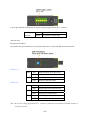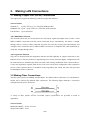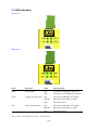
1
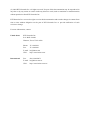
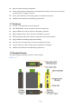
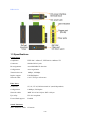
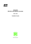
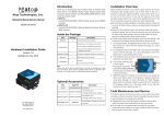
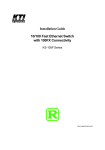
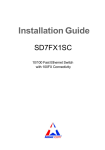
Industrial 3-Port Fast Ethernet
Media Converter Switches
KSD-103-A series
KSD-103-B series
Installation Guide
DOC.081111
1/20
(C) 2008 KTI Networks Inc. All rights reserved. No part of this documentation may be reproduced in
any form or by any means or used to make any directive work (such as translation or transformation)
without permission from KTI Networks Inc.
KTI Networks Inc. reserves the right to revise this documentation and to make changes in content from
time to time without obligation on the part of KTI Networks Inc. to provide notification of such
revision or change.
For more information, contact:
United States
KTI Networks Inc.
P.O. BOX 631008
Houston, Texas 77263-1008
Phone:
713-2663891
Fax:
713-2663893
E-mail: [email protected]
International
URL:
http://www.ktinet.com/
Fax:
886-2-26983873
E-mail: [email protected]
URL:
http://www.ktinet.com.tw/
2/20
The information contained in this document is subject to change without prior notice. Copyright (C)
All Rights Reserved.
TRADEMARKS
Ethernet is a registered trademark of Xerox Corp.
FCC NOTICE
This device complies with Class B Part 15 the FCC Rules. Operation is subject to the following two
conditions: (1) This device may not cause harmful interference, and (2) this device must accept any
interference received including the interference that may cause.
CE NOTICE
Marking by the symbol
indicates compliance of this equipment to the EMC directive of the European
Community. Such marking is indicative that this equipment meets or exceeds the following technical
standards:
EMC Class B
EN 50081-1/1992 :EN55022:1994/A1:1995/A2:1997 Class B
EN61000-3-2:2000
EN61000-3-3:1995/A1:2001
EN 55024:1998/A1:2001
IEC 61000-4-2:1995
IEC 61000-4-3:1995
IEC 61000-4-4:1995
IEC 61000-4-5:1995
IEC 61000-4-6:1996
IEC 61000-4-8:1993
IEC 61000-4-11:1994
3/20
Table of Contents
1. Introduction ................................................................................................................................5
1.1 Features.................................................................................................................6
1.2 Product Panels ......................................................................................................6
1.3 Specifications.........................................................................................................7
2. Installation ................................................................................................................................10
2.1 Unpacking............................................................................................................10
2.2 Safety Cautions ...................................................................................................10
2.3 DIN-Rail Mounting ...............................................................................................11
2.4 Panel Mounting....................................................................................................12
2.5 Applying Power....................................................................................................13
2.6 Failure Alarm Relay Output .................................................................................14
3. Making LAN Connections........................................................................................................16
3.1 Making Copper Port (RJ-45) Connections...........................................................16
3.2 Making Fiber Connections ...................................................................................16
3.3 LED Indication .....................................................................................................17
4. Applications..............................................................................................................................18
4.1 Application in Industrial Networks........................................................................18
4.2 Copper to Fiber Bridging Media Converter Application .......................................18
4.3 Bridging Multimode to Single Mode Fiber Converter Application.........................18
5. Appendix ...................................................................................................................................19
5.1 Model Definition ...................................................................................................19
5.2 Optical Specifications ..........................................................................................20
4/20
1. Introduction
The industrial rated KSD-103 Fast Ethernet switch series supports three switching-base segment
communications and benefit the following applications and make fiber deployment easier :
Copper to fiber bridging converter
Multimode fiber to single mode fiber bridging converter
Fiber cable extender
Cascaded fiber networking
Depending on the types of the network ports, two different model series are defined as follows:
Model
Copper Port (RJ-45)
Fiber Port
KSD-103-A
2 ports
1 port
KSD-103-B
1 port
2 ports
The switch also provide the following advantages:
Plug and Play
No configuration is required in using the switches. With the featured auto-negotiation function, the
switches can detect and configure the connection speed and duplex automatically for the copper ports.
The switches also provide auto MDI/MDI-X function, which can detect the connected cable and switch
the transmission wire pair and receiving pair automatically. This auto-crossover function can simplify
the type of network cables used.
Industrial Features
For industrial environment, the devices are designed with the following enhanced features exceeding
that of commercial Ethernet switches:
5/20
High and wide operating Temperature
Power input interface: Industrial screw terminal block and DC power jack for external
commercial power adapter as option
Screw panel and DIN rail mounting support for industrial enclosure
Industrial-rated Emission and Immunity performance
1.1 Features
Provide 3 switching-base network segments
Auto MDI/MDI-X crossover function on the TP copper port
Support IEEE 802.3x flow control for full-duplex operation
Support Back-pressure flow control for half-duplex operation
Wide operating temperature range for temperature critical environment
Support DIN-rail mounting and panel mounting
Provide two power input types to meet more application needs
Accept wide power input voltage range for application flexibility
Industrial-rated Emission and Immunity performance
1.2 Product Panels
The following figure illustrates the faces of the switches:
KSD-103-A
6/20
KSD-103-B
1.3 Specifications
Copper Ports
Compliance
IEEE 802.3 10Base-T, IEEE 802.3u 100Base-TX
Connectors
Shielded RJ-45 jacks
Pin assignments
Auto MDI/MDI-X detection
Configuration
Auto-negotiation
Transmission rate
10Mbps, 100Mbps
Duplex support
Full/Half duplex
Network cable
Cat.5 UTP up to 100 meters
Fiber Ports
Connectors
ST, SC, VF-45, Bi-Directional SC (model dependent)
Configuration
100Mbps, Full duplex
Network cables
MMF 50/125 60/125μm, SMF 9/125μm
Eye safety
IEC 825 compliant
Far end fault support
Enabled
Switch Functions
MAC Addresses Table
1K entries
7/20
Forwarding & filtering
Non-blocking, full wire speed
Switching technology
Store and forward
Maximum packet length 1536 bytes max.
Flow control
IEEE 802.3x pause frame base for full duplex operation
Back pressure for half duplex operation
Broadcast Storm
Protection design
DC Power Interface
Interface
Screw-type terminal block
1. Two pairs for power wire cascading
2. One pair for alarm relay output
DC Jack (-D6.3mm/+D2.0mm)
Operating voltages
+7V ~ +50V(+5%)
Power consumption
KSD-103-A
2.1W max.@+7.5VDC input, 3.5W max.@+50VDC input
KSD-103-B
3.3W max.@+7.5VDC input, 4W max.@+50VDC input
DIP SW
KSD-103-A
SW1
Broadcast storm protection setting
SW2
Fiber port FX link down alarm setting
KSD-103-B
SW1
Broadcast storm protection setting
SW2
Fiber port FX1 link down alarm setting
SW3
Fiber port FX2 link down alarm setting
Mechanical
Dimension (base)
W 28mm x D 82mm x H 95mm
Weight
250g
Housing
Enclosed metal with no fan
Mounting support
DIN-rail mounting, Panel mounting
Environmental
Operating temperature
-20oC ~ 70oC
Storage temperature
-20oC ~ 85oC
Relative humidity
5% ~ 90%
8/20
Certificate
FCC
Part 15 Class B
CE/EMC
EMI EN50081-1 Class B
EMS EN55024
CE/LVD Safety
EN 60950
EN 50081-1/1992 :
EN55022:1994/A1:1995/A2:1997
EN61000-3-2:2000
EN61000-3-3:1995/A1:2001
EN 55024:1998/A1:2001
IEC 61000-4-2:1995 ESD Test
IEC 61000-4-3:1995 RS Test
IEC 61000-4-4:1995 EFT/BURST Test
IEC 61000-4-5:1995 Surge Test
IEC 61000-4-6:1996 CS Test
IEC 61000-4-8:1993 Magnetic Field
IEC 61000-4-11:1994 Voltage Int. Dips
9/20
2.
Installation
2.1 Unpacking
Check that the following components have been included:
Information CD
The device unit
DIN-rail mounting bracket
If any item is found missing or damaged, please contact your local reseller for replacement.
The following are available optional accessories:
Panel Mounting Bracket
The bracket is used for mounting the device on a panel surface.
Commercial-rated AC power adapters:
- Rated input AC120V/60Hz, AC230V/50Hz, AC100V/50-60Hz, AC240V/50Hz
- Rated output DC7.5V 1A, DC7.5V 1.2A
High temperature AC power adapters:
- Rated -10 oC ~ 60oC, AC100-240V/50-60Hz DC12V 1A for USA and Germany
The adapters are used for supplying DC power to the switch via DC power jack interface.
2.2 Safety Cautions
To reduce the risk of bodily injury, electrical shock, fire, and damage to the product, observe the
following precautions.
Do not service any product except as explained in your system documentation.
Opening or removing covers may expose you to electrical shock.
Only a trained service technician should service components inside these compartments.
If any of the following conditions occur, unplug the product from the electrical outlet and replace
the part or contact your trained service provider:
- The power cable, extension cable, or plug is damaged.
- An object has fallen into the product.
- The product has been exposed to water.
- The product has been dropped or damaged.
- The product does not operate correctly when you follow the operating instructions.
Do not push any objects into the openings of your system. Doing so can cause fire or electric shock
by shorting out interior components.
Operate the product only from the type of external power source indicated on the electrical ratings
10/20
label. If you are not sure of the type of power source required, consult your service provider or
local power company.
2.3 DIN-Rail Mounting
In the product package, a DIN-rail bracket is installed on the device for mounting the device in a
industrial DIN-rail enclosure.
The steps to mount the device onto a DIN rail are:
1. Install the mounting bracket onto the device unit as shown below:
2. Attach bracket to the lower edge of the DIN rail and push the unit upward a little bit until the
bracket can clamp on the upper edge of the DIN rail.
3. Clamp the unit to the DIN rail and make sure it is mounted securely.
4. Make sure that there are proper heat dissipation from and adequate ventilation around the device.
11/20
The final mechanical dimensions after installing DIN rail mounting bracket are:
2.4 Panel Mounting
The product is provided with an optional bracket for panel mounting. The bracket supports mounting
the device on a plane surface securely. The mounting steps are:
1. Install the mounting bracket on the device unit. Screw the bracket on the device unit.
2. Screw the device unit on a panel. Make sure that there are proper heat dissipation from and
adequate ventilation around the device. Do not place heavy objects on the device.
The screw locations and final dimension are shown below:
12/20
2.5 Applying Power
The power specifications of the device are:
Operating Voltage
+7 ~ +50VDC
Power Consumption
4W max. @+50VDC
Using Terminal Blocks
Either DC1 interface or DC2 interface can be used to receive DC power from an external power
system. Or, DC2 also can be used to deliver the power received on DC1 to next device in cascading
way.
DC1
+Vdc Positive (+) terminal
DC1
-Vdc Negative (-) terminal
DC2
+Vdc Positive (+) terminal
DC2
-Vdc Negative (-) terminal
Three 2P terminal plugs are provided together with the device. Two of the three plugs are used for
DC1 and DC2 interfaces respectively. The plug is shown below:
Power wires: 24 ~ 12AWG (IEC 0.5~2.5mm2)
Install the power source wires with the plug properly. Screw the wire with plug securely. Then, plug in
DC1 contacts.
13/20
If cascading the power to next device is needed, install the power wires and plug for another switch.
Then, use DC2 contacts.
Note: Only up to four device units can be cascaded to receive power from one main power input
source.
Using DC Power Jack
DC Jack Connector: D 6.3mm
D 2.0mm
AC Power Adapters: Optional power adapters are available for purchasing.
Connect power adapter DC plug to the DC power jack of the converter before connecting to the AC
outlet. Connect the power adapter to the AC outlet.
Note: Before you begin the installation, check the AC voltage of your area. The AC power adapter that
is used to supply the DC power for the unit should have the AC voltage matching the
commercial power voltage in your area.
2.6 Failure Alarm Relay Output
The device provides a relay output to report failure events to a remote alarm monitoring system. The
replay output is provided with two contacts labeled PF+ and PF- in the terminal block interface.
14/20
Use the provided 2P terminal plug for signal wiring and plug into the PF+/- contacts.
Relay Output
Normal PF+ and PF- contacts shorted
Indication
Alarm PF+ and PF- contacts open
Alarm Events:
Input power failure
Specific fiber port link down (To specify the fiber ports, use the DIP SW located on bottom.)
KSD-103-A
SW1
SW2
ON
Enable broadcast storm protection
OFF
Disable broadcast storm protection
ON
Enable FX port link down alarm
OFF
Disable FX port link alarm
ON
Enable broadcast storm protection
OFF
Disable broadcast storm protection
ON
Enable FX1 port link down alarm
OFF
Disable FX1 port link alarm
ON
Enable FX2 port link down alarm
OFF
Disable FX2 port link alarm
KSD-103-B
SW1
SW2
SW3
Note: Be sure the voltage applied on PF+/- contacts is within the specification of 30VDC/1A max. or
120VAC/0.5A max.
15/20
3.
Making LAN Connections
3.1 Making Copper Port (RJ-45) Connections
The copper ports support the following connection types and distances:
Network Cables
10BASE-T:
2-pair UTP Cat. 3,4,5 , EIA/TIA-568B 100-ohm
100BASE-TX: 2-pair / 4-pair UTP Cat. 5, EIA/TIA-568B 100-ohm
Link distance: Up to 100 meters
Auto MDI/MDI-X Function
This function allows the port to auto-detect the twisted-pair signals and adapts itself to form a valid
MDI to MDI-X connection with the remote connected device automatically. No matter a straight
through cable or crossover cable connected, the ports can sense the receiving pair automatically and
configure self to match the rule for MDI to MDI-X connection. It simplifies the cable installation by
using only straight-through cables.
Auto-negotiation Function
The ports are featured with auto-negotiation function and full capability to support connection to any
Ethernet devices. The port performs a negotiation process for the speed and duplex configuration with
the connected device automatically when each time a link is being established. If the connected device
is also auto-negotiation capable, both devices will come out the best configuration after negotiation
process. If the connected device is incapable in auto-negotiation, the switch will sense the speed and
use half duplex for the connection.
3.2 Making Fiber Connections
The fiber ports operate on 100Mbps and full duplex. For different fiber connections, several alternative
models can be selected for different fiber connections. The following figure illustrates a connection
example between two SC fiber ports:
A variety of fiber options and the associated optical specifications are provided as listed in
Appendix-1.
Network Cables
Multimode (MMF) - 50/125, 62.5/125
Single mode (SMF) - 9/125
16/20
3.3 LED Indication
KSD-103-A
KSD-103-B
LED
Function
State
Interpretation
PWR
Power status
ON
The power is supplied to the device.
OFF
The power is not supplied to the device.
ON
Port link is established. (No traffic)
BLINK
Port link is up and there is traffic.
OFF
Port link is down.
ON
Port link is established. (No traffic)
BLINK
Port link is up and there is traffic.
OFF
Port link is down.
UTPx
FXx
Copper port link status
Fiber port link status
Note: UTPx = UTP UTP1 UTP, FXx = FX FX1 FX2
17/20
4.
Applications
4.1 Application in Industrial Networks
The following figure illustrates an application example in an industrial network. Four devices are
cascaded by fiber cables.
4.2 Copper to Fiber Bridging Media Converter Application
4.3 Bridging Multimode to Single Mode Fiber Converter Application
18/20
5.
Appendix
5.1 Model Definition
KSD-103-A
Model Ext.
FX Connector
Cable
Ref. Distance
Operating Temperature
-T
Duplex ST
MMF
2km
-10 ~ 70oC
-C
Duplex SC
MMF
2km
-10 ~ 70oC
-C1
Duplex SC
MMF
2km
-20 ~ 70oC
-SA2
Duplex SC
SMF
20km
-20 ~ 70oC
-SL2
Duplex SC
SMF
20km
-20 ~ 70oC
-SL3
Duplex SC
SMF
30km
-20 ~ 70oC
-SL4
Duplex SC
SMF
40km
-20 ~ 70oC
-SL6
Duplex SC
SMF
60km
-20 ~ 70oC
-W3515
BiDi SC
SMF
15 ~ 20km
-20 ~ 70oC
-W5315
BiDi SC
SMF
15 ~ 20km
-20 ~ 70oC
KSD-103-B
Model Ext.
FX Ports
FX2 Connector
Cable
Ref. Distance
Operating Temperature
-T
FX1, FX2
Duplex ST
MMF
2km
-10 ~ 70oC
-C
FX1, FX2
Duplex SC
MMF
2km
-10 ~ 70oC
-C1
FX1, FX2
Duplex SC
MMF
2km
-20 ~ 70oC
-SA2
FX1, FX2
Duplex SC
SMF
20km
-20 ~ 70oC
-SL2
FX1, FX2
Duplex SC
SMF
20km
-20 ~ 70oC
-SL3
FX1, FX2
Duplex SC
SMF
30km
-20 ~ 70oC
-SL4
FX1, FX2
Duplex SC
SMF
40km
-20 ~ 70oC
-SL6
FX1, FX2
Duplex SC
SMF
60km
-20 ~ 70oC
-W3515
FX1, FX2
BiDi SC
SMF
15 ~ 20km
-20 ~ 70oC
-W5315
FX1, FX2
BiDi SC
SMF
15 ~ 20km
-20 ~ 70oC
FX1
Duplex SC
MMF
2km
-20 ~ 70oC
FX2
Duplex SC
SMF
20km
-20 ~ 70oC
-C1Sl2
19/20
5.2 Optical Specifications
KSD-103-A
Model Ext.
FX Port
Wavelength
TX Power
Sensitivity
RX Max. Power
-T
FX
1310nm
-19 ~ -14dBm
-31dBm
-14dBm
-C
FX
1310nm
-19 ~ -14dBm
-31dBm
-14dBm
-C1
FX
1310nm
-20 ~ -14dBm
-31dBm
0dBm
-SA2
FX
1310nm
-15 ~ -8dBm
-31dBm
-7dBm
-SL2
FX
1310nm
-15 ~ -8dBm
-30dBm
0dBm
-SL3
FX
1310nm
-15 ~ -8dBm
-34dBm
0dBm
-SL4
FX
1310nm
-5 ~ 0dBm
-34dBm
0dBm
-SL6
FX
1310nm
-5 ~ 0dBm
-35dBm
0dBm
-W3515
FX
1310nm
-14 ~ -8dBm
-31dBm
0dBm
-W5315
FX
1550nm
-14 ~ -8dBm
-31dBm
0dBm
Model Ext.
FX Ports
Wavelength
TX Power
Sensitivity
RX Max. Power
-T
FX1, FX2
1310nm
-19 ~ -14dBm
-31dBm
-14dBm
-C
FX1, FX2
1310nm
-19 ~ -14dBm
-31dBm
-14dBm
-C1
FX1, FX2
1310nm
-20 ~ -14dBm
-31dBm
0dBm
-SA2
FX1, FX2
1310nm
-15 ~ -8dBm
-31dBm
-7dBm
-SL2
FX1, FX2
1310nm
-15 ~ -8dBm
-30dBm
0dBm
-SL3
FX1, FX2
1310nm
-15 ~ -8dBm
-34dBm
0dBm
-SL4
FX1, FX2
1310nm
-5 ~ 0dBm
-34dBm
0dBm
-SL6
FX1, FX2
1310nm
-5 ~ 0dBm
-35dBm
0dBm
FX1
1310nm
-14 ~ -8dBm
-31dBm
0dBm
FX2
1550nm
-14 ~ -8dBm
-31dBm
0dBm
FX1
1550nm
-14 ~ -8dBm
-31dBm
0dBm
FX2
1310nm
-14 ~ -8dBm
-31dBm
0dBm
FX1
1310nm
-20 ~ -14dBm
-31dBm
0dBm
FX2
1310nm
-15 ~ -8dBm
-30dBm
0dBm
KSD-103-B
-W3515
-W5315
-C1Sl2
20/20