1
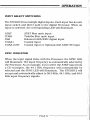
STUDIO
2
O
O
0
0
0
STUDIO 2 DIGITAL
OWNER’S
0
0
0
0
TO ANALOG PROCESSOR
REFERENCE
INTRODUCTION
Thank you for your purchase of the Krell STUDIO 2 Digital-toAnalog Processor
and welcome to the Krell family of audio
components. Krell is dedicated to the development of technologically advanced components for the reproduction
of digitally
recorded music. The STUDIO 2 continues
the Krell tradition
of
uncompromising
performance
through leading-edge
technology.
To obtain the best performance
from your STUDIO 2 Processor,
careful attention should be paid to its placement, installation
and
operation.
A thorough understanding
of these details
will help
insure satisfactory
operation and long life for the STUDIO2 and
related
system components.
This Owner’s Reference is divided into several
sections
which
describe the features
and functions
of the STUDIO2. A Question
and Answer section
is included
to provide answers to common
questions.
Shouldyou have any questions
or suggestions,
please
feel free to contact your authorized dealer or the KRELLstaff for
assistance.
In the unlikely event that your STUDIO2 should require service,
you will be pleased to know that it is backed by a comprehensive
Customer Satisfaction
policy
and one of the most advanced
service facilities
in the industry. For detailed information on the
terms and conditions
of service,
please consult the Warranty and
Service section of this Reference, Warranty Registration
Card, or
authorized
KRELL Dealer/Distributor.
PAGE2
.......
4
5
6
7
TABL~ OF CONTENTS
UNPACKING
INSTRUCTIONS
PLACEMENT
AC POWER CONSIDERATIONS
INPUT
AND OUTPUT CONNECTIONS
i i
PROCESSOR
OPERATION
13
OPERATING
15
QUESTIONS
18
SPECIFICATIONS
19
WARRANTY AND SERVICE
INSTRUCTIONS
AND ANSWERS
INFORMATION
PAGE 3
UNPACKING
UNPACKING INSTRUCTIONS
1. Open the box and remove the top layer
items will now be visible:
STUDIO 2 D/A Processor
AC power cord
Packet containing
the Owner’s
Card
of foam. The following
Reference
NOTE: If any of these items are not included,
authorized
dealer immediately for assistance.
2. Carefully
remove the STUDIO 2 from the
protective
plastic wrap from the Processor.
and Warranty
please
box.
contact
your
Remove the
NOTE: Save all packing materials.
If you must ship your
STUDIO2 in the future, repack the unit in its original packaging
to prevent transit
damage.
PAGE
PLACEMENT
PLACEMENT
Before you install
the STUDIO 2 into your system, we recommend
that you follow these guidelines in choosing the location. This will
facilitate
a clean, trouble-free installation.
1. Although well shielded,
the STUDIO2 should not be placed in
close proximity
to hum-sensitive
components (i.e.
preamps,
turntables,
tuners, etc.) that can create interference
and induce
hum.
2. As with any high quality
component, ensure that the vent
openings in the chassis are free from obstruction,
allowing the
Processor to dissipate
heat created by its power supply and Class
A output stage. Place the unit on a clean, level surface away from
excessive dirt or moisture.
Make sure the STUDIO2 has at least
2 inches of clearance on either side and 2-3 inches of space at the
top. Components that are heat sensitive
should not sit directly
above the unit.
3. The STUDIO 2 does not require
additional
mass coupling
or
isolation.
You may experiment with feet or cones as long as they
do not permanently
affix
to the chassis.
Any unauthorized
modifications to the electronics
or chassis will void the warranty.
PAGE 5
AC POWER
AC POWER CONSIDERATIONS
NOTE: While the STUDIO 2 has superb regulation
and does not
require a dedicated
AC circuit,
we strongly
advise against any
connections
through extension
cords or multiple
AC adaptors.
High quality
15 amp grounded AC strips
are acceptable.
High
quality AC line conditioners
or filters
can be utilized if they are
grounded and meet or exceed the unit’s
power supply rating
of
150VA.
CAUTION: Do not remove or bypass the ground pin on the end
of the AC cord. This may cause RFI (radio frequency interference)
to be induced into your playback system.
PAGE 6
CONNECTIONS
INPUT AND OUTPUT CONNECTIONS
CAUTION: When making connections
other, make sure the power amplifier
is in the MUTEor STANDBYmode.
to this component or any
is OFF and the preamplifier
1. Connect the power cord to the back of the STUDIO2 and plug
the unit into the wall AC receptacle.
2. Connect the STUDIO2 analog output to the line level input of
your preamplifier.
The STUDIO2 is equipped with two analog output configurations:
Single-ended via RCAconnectors and balanced via XLR connectors. If your preamplifier
has high level balanced inputs, we
recommend the balanced outputs of the Processor be used. There
are considerable sonic benefits associated with the use of balanced
interconnection.
The XLRpin configuration
Pin 1
Pin 2
Pin 3
is described
below.
Ground
°)
Non-inverting (0
°)
Inverting ( 180
NOTE: The two outputs
different systems.
can be used to simultaneously
feed
NOTE:If you decide to use the single-ended analog outputs, the
type of interconnect
cable should be chosen carefully.
High
quality shielded cable is suggested.
PAGE 7
CONNECTIONS
3. The Left and Right channel RCA outputs
are labeled on the
back panel. The balanced outputs are not labeled.
The balanced
connector closest to the Left RCAoutput is for the left channel
output and the connector closest
to the RCAright output is the
right balanced output.
Care should be taken to insure that the
channel orientation
between the Processor
and the high level
inputs of your preamplifier
is maintained.
4. Connect the digital
output of your CD transport
and other
digital
sources to the inputs of the STUDIO2. If you are using
multiple
digital
sources,
take note of where each input and
corresponding switch setting is located.
The STUDIO2 is equipped with the following inputs: two coaxial,
one AT&Twide bandwidth fiber optic, standard TOSHfiber optic,
and one AES/EBU. All inputs can accept a signal from any digital
source such as Compact Disc players,
Laser Disc players,
DATs
or satellite
receivers.
When a powered digital source is introduced
to an input and that input is selected
with the specific
Input
switch, the corresponding
signal LED will illuminate.
When the
source and the Processor
have locked the SYNC indicator
LED
will illuminate.
The STUDIO 2 has a provision
to add an additional
AT&T input.
The second AT&Tinput will replace the Coax 2 space on the back
panel and is selected
by the COAX2/STinput switch. For further
information
contact
KRELL.
NOTE: If the digital
source is ON and the signal LED does not
illuminate,
check to make sure the digital
interconnect
cable is
secure at both ends or is not in need of repair.
PAGE8
CONNECTIONS
5. Once you have completed the necessary
input and output
connections,
select the input of your choice. For each input
selected, the corresponding LEDwill illuminate.
When a powered
digital input source and the Processor have linked, the SYNCLED
will illuminate.
~,
DIGITAL SOURCE TO D/A PROCESSOR INTERLINK CONSID
ERATIONS
Care should be taken in selecting the type of cable used to link the
digital
source to your Processor.
We suggest the AT&Twidebandwidth fiber optic cable be used. The AT&Tformat has a
bandwidth of approximately
50 MegaBit. This allows accurate
transmission of the digital bit stream without data corruption
and proves to be sonically superior. If the AT&Tformat is not
available, a high quality quartz fiber optic cable (TOSHformat)
can work well. Using a fiber optic interconnect reduces ground
loop problems often associated with quality audio systems.
If coaxial cable is used, it should be non-capacitive and have a
bandwidth in excess of 10MHzto prevent drop-out errors.
For
best results
with coaxial
cable we recommend the AES/EBU
balanced format. The AES/EBU format is a + 5 volt balanced
digital transmission. Because of the high voltage balanced format, this system allows for accurate data transmission and has
great sonic advantages over standard single-ended
coaxial or
Tosh fiber optic terminations.
The AES/EBUcoaxial cable must
have two conductors and a shield for balanced termination.
PAGE 9
CONNECTIONS
How to connect
AT&Tcables:
a. Remove the plastic
cover from the outside
of the AT&T
transmitter (located on Transport) and receiver (located on Proeessor).
b. Locate the slot on the top of the AT&Treceptacle.
e. Locate the key on the top of the AT&Tcable.
d. Removethe plastic
cap from both ends of the fiber optic cable.
e. Slide the cable connector into the AT&Treceptacle
sliding into the designated slot.
with the key
f. Gently push the connector into place, depressing the internal
spring, and twist the outer collar clockwise to secure the connection.
PAGE 10
OPERATION
INPUT
SELECT SWITCHING
The STUDIO2 has multiple digital
inputs. Each input has its own
input switch and direct path to the digital
Processor.
When an
input is selected,
the corresponding
LED will illuminate.
AT&T
TOSH
XLR
COAX1
COAX 2/ST
AT&Tfiber optic input
Toshiba fiber optic input
Balanced AES/EBU digital
input
Coaxial input
Coaxial input or Optional-2nd
AT&T ST input
SYNC INDICATOR
When the input signal
locks with the Processor,
the SYNC LED
will illuminate.
The input frequency is automatically
selected by
the Processor.
As an example, if you select the AT&Tinput from
a CD transport,
the 44.1 KHz frequency will automatically
be
selected
and the SYNCLED will illuminate.
The STUDIO 2 will
accept and automatically
adjust to 38.0 KHz, 44.1 KHz, and 48.0
KHz input frequency signals.
PAGE11
OPERATION
0 ° and
180 ° PHASE SWITCHING
The absolute
output phase of the STUDIO 2 can be changed. In
some recordings
the master tape was recorded
out of phase,
creating
unusually
poor sounding recordings.
The STUDIO 2 can
°
shift the absolute output phase 180 to correct for this anomaly.
To change the phase from 0 ° to 180 °, press the 180 DEG button.
To change back to normal phase,
press
the 0 DEG button.
Utilizing the Phase Switching can, in some instances,
restore life
to a previously dull sounding recording.
EMPHASIS
LED
Emphasis is a recording
technique that accentuates
the treble
region of recorded music. Discs and/or Tracks that were recorded
with Pre-emphasis
will cause the Emphasis LED to illuminate.
When the Emphasis LED is lit,
the appropriate
complementary
circuitry
(De-emphasis)
is activated
to provide a fiat output
response.
PAGE12
OPERATION
OPERATING INSTRUCTIONS
1. Select an input with the Input switch. Notice the Signal LED
will illuminate when the digital source is turned on and has linked
with the Processor. Once this link is complete, the Processor is
ready to pass a signal.
2. Be sure that your preamplifier
volume control
completely to the OFF (lowest volume) position.
is turned
3. Turn ON your components, remembering that the last component to be energized should be your amplifier.
The amplifier
should only be turned ON after all other components in the
system have been on for at least two minutes. This will insure
that no large pulse will be created when the amplifier is turned on.
4. Switch the source selector
of your preamp to the position
correlating
to your chosen input connection for the STUDIO2.
5. You may now start
satellite.
playing
your digital
source,
DAT, CD or
6. Slowly turn the volume control up to the lowest level you can
hear. Check to see that both channels are working correctly
before advancing the volume.
PAGE 13
’ " ’"
OPERATION
NOTE: While your STUDIO2 will perform beautifully
from the
moment you turn it on, it requires a minimum warm-up period
of 8 hours before it begins to show its strongest sonic qualities.
It will continue to improve over time. Discrete components are
utilized in the analog output stage and the warm-up period allows
them to reach thermal equilibrium.
Your installation
is now complete. Should you have any further
questions which are not covered in the remainder of this Reference, contact your authorized Krell dealer. We wish you many
hours of listening fulfillment.
PAGE 14
QUESTIONS
Q. My CD player has both fiber
one should I use?
AND ANSWERS
optic and coaxial outputs.
Which
A. Given a choice, we prefer the AT&Toptical link due to its ability
to completely isolate the grounds between the digital
source
component and the Processor. This minimizes the possibility
of
ground loops in the digital
components. The AT&Tformat also
has the added benefit of substantially
higher bandwidth than
coax or the standard fiber optic interface. If a coax cable must be
used, we suggest the AES/EBU balanced format. This interconnection utilizes
a + 5v digital
format and the additional
benefit of balanced termination.
Q o Will I damage my STUDIO2 if I leave the power "ON" all
time?
the
A. No. The Class A discrete analog circuits perform more consistently once they reach thermal equilibrium.
This Processor has
been designed to be left On at all times. The STUDIO2 draws less
than 30 watts out of the AC mains socket.
NOTE: For the protection
of your Processor,
we recommend
disconnecting
the AC cord from the wall outlet
before any
electrical
storms or if you plan on being away from home for
prolonged periods of time.
PAGE 15
QUESTIONS
AND ANSWERS
Q. Do I have to switch
my CD and DAT?
the Sampling Frequency
A. No. Your STUDIO 2 automatically
and does all necessary switching.
Q. I am not getting
be wrong?
any sound through
senses
the
when I go between
input
the Processor.
frequency
What could
A. Most likely there has been a simple mistake in installation.
Check all connections IN and OUTof the Processor. Is the digital
source component powered? Check all power connections.
Have
you selected
the correct
source on the STUDIO 2 and preamp?
Check the front panel LED’s for power supply stability.
If you still
have no sound, turn off the power and contact your dealer.
Q. I have some very fine audiophile interconnect.cable
which has
superior sonic characteristics.
Can I use this for my coaxial digital
input?
A. You may experiment with any high quality cable. Do note that
most audio interconnect
cable is not designed to carry the ultrahigh frequency information of the digital
bit stream.
NOTE: For the STUDIO 2, we recommend non-capacitive
coaxial
cable which has a bandwidth in excess of 10MHz and excellent
shielding properties.
PAGE16
QUESTIONS
AND ANSWERS
Q. While listening
to my STUDIO 2 I experience
occasional
periods of silence through my speakers. Is my Processor malfunctioning?
A. Drop outs are caused by two primary reasons. First, drop outs
can be caused by data corruption. Corruption in the data may be
due to a poor input connection, damaged or dirty source material,
or interconnects
which do not have wide enough bandwidth. The
second item that causes the Processor to reset is the presence of
a transient spike on the incoming AC power line. The Processor
is resetting all of its digital processing circuits so that it can be
assured that all are properly synchronized. Try changing your
source material and check your connections. If these are not the
cause, speak with your dealer about obtaining different cabling.
If you are using fiber optics, and source material and connections
are not the problem, speak with your authorized dealer.
Q. Since I installed
hum that increases
in my system until
malfunctioning?
the Processor in my system I have a low level
as I turn up the volume. There was no hum
I added the Processor.
Is the Processor
Ao The fact that there was no hum in your system until you added
the Processor indicates
that you have a ground-loop problem.
Often changing the interconnect
to a fiber optic cable will
eliminate this problem. The way the digital Processor and digital
source are connected to the AC mains often can be the cause of
grounding problems. Check for loose interconnect
cables and or
bad electrical
connections.
Consult your dealer or Krell for
individual system suggestions if this hum persists.
PAGE 17
SPECIFICATIONS
FREQUENCY RESPONSE
-.3 dB@ 20KHz and at 8Hz
SIGNAL TO NOISE
> 115dB
DIGITAL-TO-ANALOG
18 bit
CONVERTER
PROCESSING
1 Motorola
DSP-56001
Upgradable
software
contained
in socketed
LINEAt~TY
+ .3dB at -90dB
THD +N
.0025%
-92dB
CHANNEL SEPARATION
>_ 109dB
ANALOG OUTPUT
2.00 volts
VOLTAGE
DIMENSIONS
19.00" WIDE
12.50"
DEEP
2.50" TALL(with feet)
SHIPPING
16 pounds
WEIGHT
PAGE18
EPROM.
WARRANTY AND SERVICE
WARRANTY AND SERVICE
INFORMATION
There are no user-serviceable
parts inside the STUDIO2. The
STUDIO2 has a limited warranty of five years parts and labor.
Return freight is included in the warranty. The warranty period
begins on the date of purchase and is activated with the return
of the enclosed Warranty Card and a copy of the Sales receipt.
Please return the Warranty Card immediately after successful
installation
and operation are completed.
The warranty for Krell products is valid only in the country to
which they were originally shipped and at the factory. If you think
there are problems with your unit, please contact your dealer,
distributor
or the factory immediately.
The operating voltage of this unit is determined by the factory and
can only be changed by an authorized KRELLdistributor
or the
KRELLfactory. Any unauthorized voltage conversion will void the
warranty. Should the operating voltage of your STUDIO2 require
changing, contact KRELLIndustries.
Please do not return any unit to KRELLfor repair without first
calling to discuss the problem and to obtain a Return Authorization number. Freight to the factory or distributor
is your responsibility.
Return freight to you will be paid by the factory or
distributor.
Any unauthorized disassembly, updates or modifications performed to the unit will void the warranty.
PAGE 19
KRELL
35 Higgins Drive Milford CT 06460
SALES (203) 874-3139
FAX (203) 878-8373
© 1993 KRELL DIGITAL
(STUDIO29303)