1
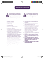
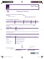
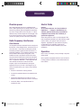
splitter
operator
manual
DOC02-SQ1SPLITTER_Square ONE Splitter_Op_IssC.pdf 1
27/04/2010 17:00:41
DOC02-SQ1SPLITTER_Square ONE Splitter_Op_IssC.pdf 2
27/04/2010 17:00:42
OPERATOR MANUAL
Midas Klark Teknik Limited
Klark Industrial Park
Walter Nash Road
Kidderminster
Worcestershire
DY11 7HJ
England
Tel: +44 1562 741515
Fax: +44 1562 745371
Email: [email protected]
Website: www.ktsquareone.com
Square ONE Splitter - Operator Manual
DOC02-SQ1SPLITTER Issue C - April 2010
© Red Chip Company Ltd.
In line with the company’s policy of continual improvement, specifications and function may be
subject to change without notice. This Operator Manual was correct at the time of writing. E&OE.
DOC02-SQ1SPLITTER_Square ONE Splitter_Op_IssC.pdf 3
27/04/2010 17:00:42
DOC02-SQ1SPLITTER_Square ONE Splitter_Op_IssC.pdf 4
27/04/2010 17:00:42
IMPORTANT SAFETY INSTRUCTIONS
The lightning flash with arrowhead symbol
within an equilateral triangle, is intended to
alert the user to the presence of uninsulated
“Dangerous Voltage” within the product's
enclosure that may be of sufficient magnitude
to constitute a risk of electric shock to persons.
1
Read these instructions.
2
Keep these instructions.
3
Heed all warnings.
4
Follow all instructions.
5
Do not use this apparatus near water.
6
Clean only with a dry cloth.
7
Do not block any of the ventilation openings. Install
in accordance with the manufacturer’s instructions.
8
Do not install near any heat sources such as
radiators, heat registers, stoves, or other apparatus
(including amplifiers) that produce heat.
9
10
Do not defeat the safety purpose of the polarized or
grounding-type plug. A polarized plug has two
blades with one wider than the other. A grounding
type plug has two blades and a third grounding
prong. The wide blade or the third prong are
provided for your safety. If the provided plug does
not fit into your outlet, consult an electrician for
replacement of the obsolete outlet.
Protect the power cord from being walked on or
pinched particularly at plugs, convenience
receptacles, and the point where they exit from the
apparatus.
DOC02-SQ1SPLITTER_Square ONE Splitter_Op_IssC.pdf 5
The exclamation point within an equilateral
triangle, is intended to alert the user to the
presence of important operating and
maintenance (servicing) instructions in the
literature accompanying the product.
11
Only use attachments/accessories specified by the
manufacturer.
12
Unplug this apparatus during lightning storms or
when unused for long periods of time.
13
Refer all servicing to qualified personnel. Servicing is
required when the apparatus has been damaged in
any way, such as power supply cord or plug is
damaged, liquid has been spilled or objects have
fallen into the apparatus, the apparatus has been
exposed to rain or moisture, does not operate
normally, or has been dropped.
14
Use the mains plug to disconnect the apparatus from
the mains.
15
Warning: To reduce the risk of fire or electric
shock, do not expose this apparatus to rain or
moisture.
16
Do not expose this equipment to dripping or
splashing and ensure that no objects filled with
liquids, such as vases, are placed on the
equipment.
17
The mains plug of the power supply cord shall
remain readily operable.
27/04/2010 17:00:42
DOC02-SQ1SPLITTER_Square ONE Splitter_Op_IssC.pdf 6
27/04/2010 17:00:42
Klark Teknik
EC-Declaration of Conformity
The undersigned, representing the following manufacturer
Manufacturer:
Address:
Midas Klark Teknik Limited
Klark Industrial Park, Walter Nash Road,
Kidderminster, Worcestershire DY11 7HJ
hereby declares that the following product
Product Type Number
Product Description
Nominal Voltage(s)
Current
Freq.
Square ONE Splitter
Microphone Splitter
115V AC
230V AC
400mA
200mA
50/60Hz
is in conformity with the regulations of the following marked EC-directive(s) and bears the
accordingly
Reference Number
Title
2004/108/EC
EMC Directive (EMC)
2006/95/EC
Low-Voltage Directive (LVD)
-mark
The conformity of the product with EC Directives for use in environments E1, E2, E3 and E4 is provided by the compliance
with the following standards:
Standards/date
Reference Number
Title
EN50081/1
Generic Standard Using EN55103 Limits and Methods
EN55103
Class B Conducted Emissions PAVI
EN55103
Class B Radiated Emissions PAVI
EN61000-3-3:2000
Voltage Fluctuation and Flicker
EN61000-3-2:1995
Harmonic Current Emissions
EN60065:2002
Electrical Safety
Place, date: Kidderminster, UK
15th April 2010
General Manager
Printed name: John Oakley
DOC02-SQ1SPLITTER_Square ONE Splitter_Op_IssC.pdf 7
AVP, Product Development
Printed name: Alex Cooper
27/04/2010 17:00:42
DOC02-SQ1SPLITTER_Square ONE Splitter_Op_IssC.pdf 8
27/04/2010 17:00:42
PRECAUTIONS
This equipment is supplied by a mains voltage that can cause electric shock injury!
The following special limitations must be observed in order to maintain safety and electromagnetic compatibility
performance.
Power
Installation
The internal power supply is a switch mode type that
automatically senses the incoming mains voltage and will
work where the nominal voltage is in the range 100V a.c.
to 240V a.c.
Before installing and connecting up the equipment, check
that both the mains supply and the quality of earthing are
adequate for the equipment. Also check that the mains
power supply voltage rating corresponds with the local
mains power supply and that the mains fuse is of the
correct type and rating.
A single, fused IEC mains inlet is provided on the rear
panel. The correct lead for connection in the area to
which the unit was shipped is supplied with the unit. The
equipment should only be plugged into the mains outlet
using the supplied lead.
When removing the equipment’s electric plug from an
outlet, always hold the plug itself and not the cable, as
pulling out the plug by the cable can damage it, and never
insert or remove an electric plug with wet hands.
Grounding
In the event of ground loop problems, use the earth LIFT
switches provided on both sets of outputs (rear panel). If
you have ground loop problems relating to the inputs, use
a DI box, for example, Klark Teknik’s DN100, to provide
isolation.
Handling the equipment
Before moving the equipment, disconnect it from the
mains, and when lifting or moving it, always take its size
and weight into consideration.
Avoid inserting or dropping foreign objects, such as paper,
plastic, metal etc., into any gaps or openings on the
equipment, for example, vents. If this happens, turn off
the power immediately and unplug the power from the
a.c. outlet. Then have the equipment inspected by the
manufacturer's qualified service personnel.
DOC02-SQ1SPLITTER_Square ONE Splitter_Op_IssC.pdf 9
Unless advised otherwise, optional equipment must only
be installed by service personnel and in accordance with
the appropriate assembly and usage regulations.
Location
Ideally, a cool, well ventilated area is preferred, away
from power distribution equipment or other potential
sources of interference. Do not install this equipment in a
location subjected to excessive heat, dust or mechanical
vibration and keep the equipment out of direct sunlight.
Where necessary use fan cooled racks.
This unit is only intended for rack mounting.
Audio connections
To ensure the correct and reliable operation of your
Square ONE Splitter, only high quality balanced,
screened, twisted pair audio cable should be used. XLR
connector shells should be of metal construction so that
they provide a screen when connected to the unit and
should have Pin 1 connected to the cable screen.
27/04/2010 17:00:42
PRECAUTIONS
Phantom power
Electric fields
Never apply phantom power to any unbalanced input
source. Before powering the unit, always check the +48V
status of any phantom powered equipment connected to
any of the 16 output XLRs on the rear panel. If +48V is
detected on any of these outputs the unit will apply +48V
to any devices connected to their corresponding inputs
(front or rear panel) as soon as the unit is powered up.
Caution:
In accordance with Part 15 of the FCC Rules &
Regulations, “… changes or modifications not
expressly approved by the party responsible for
compliance could void the user's authority to
operate the equipment.”
Radio frequency interference
Class B device
This equipment has been tested and found to comply with
the limits for a Class B digital device, pursuant to part 15
of the FCC Rules. These limits are designed to provide
reasonable protection against harmful interference in a
residential installation. This equipment generates, uses,
and can radiate radio frequency energy and, if not
installed and used in accordance with the instructions,
may cause harmful interference to radio communications.
However, there is no guarantee that interference will not
occur in a particular installation. If this equipment does
cause harmful interference to radio or television
reception, which can be determined by turning the
equipment off and on, the user is encouraged to try to
correct the interference by one or more of the following
measures:
•
Reorient or relocate the receiving antenna.
•
Increase the separation between the equipment and
receiver.
•
Connect the equipment into an outlet on a circuit
different from that to which the receiver is connected.
•
Consult the dealer or an experienced radio TV
technician for help.
DOC02-SQ1SPLITTER_Square ONE Splitter_Op_IssC.pdf 10
Should this product be used in an electromagnetic field
that is amplitude modulated by an audio frequency signal
(20Hz to 20kHz), the signal to noise ratio may be
degraded. Degradation of up to 60dB at a frequency
corresponding to the modulation signal may be
experienced under extreme conditions (3V/m, 90%
modulation).
Operation
Never remove, for example, covers, housings or any other
safety guards.
Never operate the equipment with the covers removed or
if safety guards are ineffective or their effectiveness has
been reduced.
27/04/2010 17:00:42
Contents
Contents
Introduction . . . . . . . . . . . . . . . . . . . . . . . . . . . . . . . . . . . . . . . . .1
About the Square ONE Splitter
Features
How to use the Square ONE Splitter
Using the main inputs
Using the outputs
Using the parallel inputs
1
3
4
4
4
5
Getting started . . . . . . . . . . . . . . . . . . . . . . . . . . . . . . . . . . . . . . .6
Unpacking
Checking the mains fuse
Installation
Connecting the power cable
Connecting the audio cables
6
6
6
7
7
Channel I/O pin-outs
Connecting to unbalanced equipment
Powering the unit
7
8
8
Front panel . . . . . . . . . . . . . . . . . . . . . . . . . . . . . . . . . . . . . . . . . .9
FIXED GAIN ISOLATED OUTPUT C / PARALLEL INPUT section
ACTIVE SPLITTER section
Phones, power and media split section
9
10
11
Rear panel . . . . . . . . . . . . . . . . . . . . . . . . . . . . . . . . . . . . . . . . . .12
Channel I/O connections
Media split and ground lift switches
Mains supply
12
13
13
Operation . . . . . . . . . . . . . . . . . . . . . . . . . . . . . . . . . . . . . . . . . .14
Basic operation
Solo bus operation
Using headphones
Media split mode
Using the ground lift switches
14
14
14
15
15
Applications. . . . . . . . . . . . . . . . . . . . . . . . . . . . . . . . . . . . . . . . .16
Example 1 - FOH and MON split, and broadcast out
Example 2 - FOH and MON split, and recorder
Example 3 - Pre-mixed broadcast output
16
17
18
Audio signal path . . . . . . . . . . . . . . . . . . . . . . . . . . . . . . . . . . . .19
Square ONE Splitter
DOC02-SQ1SPLITTER_Square ONE Splitter_Op_IssC.pdf 11
i
27/04/2010 17:00:42
Contents
Technical specification . . . . . . . . . . . . . . . . . . . . . . . . . . . . . . . .20
Crib sheet . . . . . . . . . . . . . . . . . . . . . . . . . . . . . . . . . . . . . . . . . .22
More about splitters . . . . . . . . . . . . . . . . . . . . . . . . . . . . . . . . . .23
Introduction
Passive parallel splitter
Isolated splitter
Active splitter
23
24
25
26
Balanced audio . . . . . . . . . . . . . . . . . . . . . . . . . . . . . . . . . . . . . .27
Service information . . . . . . . . . . . . . . . . . . . . . . . . . . . . . . . . . . .28
Routine maintenance
Cleaning the unit
Checking/replacing the mains fuse
28
28
28
Introduction . . . . . . . . . . . . . . . . . . . . . . . . . . . . . . . . . . . . . . . . .1
About the Square ONE Splitter
Features
1
3
Using the main inputs
3
Front panel . . . . . . . . . . . . . . . . . . . . . . . . . . . . . . . . . . . . . . . . . .4
FIXED GAIN ISOLATED OUTPUT C / PARALLEL INPUT section
ACTIVE SPLITTER section
4
5
Operation . . . . . . . . . . . . . . . . . . . . . . . . . . . . . . . . . . . . . . . . . . .6
Basic operation
6
Applications. . . . . . . . . . . . . . . . . . . . . . . . . . . . . . . . . . . . . . . . . .7
Example 1 - FOH and MON split, and broadcast out
7
Audio signal path . . . . . . . . . . . . . . . . . . . . . . . . . . . . . . . . . . . . .8
Technical specification . . . . . . . . . . . . . . . . . . . . . . . . . . . . . . . . .9
Crib sheet . . . . . . . . . . . . . . . . . . . . . . . . . . . . . . . . . . . . . . . . . .11
. . . . . . . . . . . . . . . . . . . . . . . . . . . . . . . . . . . . . . . . . . . . . . . . . .12
ii
DOC02-SQ1SPLITTER_Square ONE Splitter_Op_IssC.pdf 12
Square ONE Splitter
27/04/2010 17:00:42
Introduction
Introduction
Thank you for purchasing a Klark Teknik Square ONE Splitter. Your Square ONE Splitter forms an integral
part of the Square ONE range, which was conceived by Klark Teknik to offer audio professionals a suite of
easily accessible, high-performance audio equipment, designed to provide no-compromise sonic quality with
a feature set that offers all essential facilities and functions. It represents the very best of British design and
engineering combined with contemporary, efficient manufacturing methods, and will give you many years of
reliable service.
All this is backed up, of course, by the standard Klark Teknik three-year warranty.
Please take the time to complete and return the registration card or fill in the Warranty Registration Form
online by visiting our website at www.ktsquareone.com and, to obtain the best results with a minimum of
effort, also read this operator manual.
Finally, enjoy your Klark Teknik Square ONE Splitter!
About the Square ONE Splitter
The Square ONE Splitter is a user-friendly, high-performance, eight-channel, active microphone (mic) splitter
designed for live sound reinforcement. Housed in a rugged and compact 2U rack enclosure, the Square ONE
Splitter offers a cost-effective and space-effective method of providing up to 24 outputs from 8 sources. In
addition, the Square ONE Splitter can also function as a 1 x 16 media splitter.
The Square ONE Splitter can distribute up to eight mic or line level signals to multiple locations, while
maintaining signal integrity and minimising noise interference. Its primary application is to split the audio
signals on-stage into individual feeds for front of house (FOH), monitoring (MON), multi-track recording, live
broadcasting or indeed any other requirement; see Figure 1, “Typical channel I/O connection options,” on
page 2. Although the Square ONE Splitter is a cost-effective unit, its signal integrity and audio performance
mean it can be used with any console, and the quality of its preamp and circuitry can enhance the audio
performance of lower cost consoles.
The Square ONE Splitter has eight channels, each consisting of two parallel inputs, two preamps, and a total
of three balanced outputs. Two of the outputs (identical) are electronically balanced, while the other is
transformer isolated. Both paralleled mic inputs feed two integral, superbly specified mic preamps, which are
based on the circuitry used in the DL431 Mic Splitter (part of the acclaimed Midas XL8 Live Performance
System). One preamp provides adjustable gain and drives the two electronically balanced outputs at
increased levels (up to line level), while the second provides a fixed gain copy of the input and drives the
transformer isolated output.
Channel controls consist of: solo, filter and phantom voltage pushbutton switches each with an adjacent LED
for on/off indication; a gain control knob; and a dedicated peak reading meter for displaying the output at all
times. The solo system allows any channel(s) to be monitored via the integral headphone amplifier. The gain
control knob is used for optimising the preamp gain. Standard +48V phantom powering is individually
switchable on each channel and has remote operation by virtue of its unique phantom voltage sensing
feature.
Additional controls include a headphone level control (just above a headphone jack), a global ground lift
switch per set of electronically balanced outputs and a media split switch. The media split switch activates
media split mode, in which the output of channel 8 is distributed to all 16 electronically balanced outputs.
Square ONE Splitter
DOC02-SQ1SPLITTER_Square ONE Splitter_Op_IssC.pdf 13
1
27/04/2010 17:00:42
Introduction
All audio connections are on balanced XLRs (wired pin 2 hot) featuring gold plated connectors. The mic
inputs and transformer balanced outputs are mounted on the front panel for easy access, and the two
electronically balanced outputs are on the rear panel along with the duplicate set of inputs.
An integral switch mode power supply automatically adapts to mains voltages in the range 100 to 240 volts
(50 to 60Hz). An LED on the front panel indicates when power is applied to the unit; there is no mains power
on/off switch.
Analogue or digital
multi-track recorder
Broadcast
Outside
Broadcast
FOH console
(for example, the
Midas Verona)
Electronically
Mobile
Recording
Studio
Transformer balanced output
balanced output
Recording
MON console
(for example, the
Midas Siena)
Electronically
balanced output
Keyboard
Mic
Guitar
Parallel inputs
Or
Front panel
Rear panel
Figure 1: Typical channel I/O connection options
2
DOC02-SQ1SPLITTER_Square ONE Splitter_Op_IssC.pdf 14
Square ONE Splitter
27/04/2010 17:00:42
Introduction
Features
The Square ONE Splitter has eight channels, each with:
•
Two mic preamps, based on those used in the acclaimed Midas XL8 Live Performance System1; one drives
the two electronically balanced outputs and the other drives the transformer isolated output.
•
Two paralleled inputs, one front and one rear.
•
Two electronically balanced outputs (rear panel), derived from the front control knob-adjusted mic
preamp.
•
One transformer isolated output (front panel), derived from a second fixed gain preamp.
Each channel is clearly labelled and includes the following controls:
•
Rotary gain switch with nine positions. Range is from 0dB to +40dB in 5dB steps.
•
+48V phantom power switch with adjacent LED for on/off indication.
•
30Hz high pass filter switch with adjacent LED for on/off indication.
•
Solo switch with adjacent LED for on/off indication.
•
Output meter with four LEDs, which indicate -15dB, 0dB, +12dB and +21dB.
Additional features include:
•
Headphone output (1/4” jack) and level control to monitor the solo bus.
•
Two global ground lift switches, one for each set of electronically balanced outputs.
•
Media split switch for routing channel 8 to all 16 electronically balanced outputs.
•
Phantom power sensing for remotely enabling +48V on the inputs when phantom power is activated from
any attached console.
•
Male (output) and female (input) XLRs with gold plated connectors.
•
Power LED for on/off indication.
•
Mains supplied via an IEC socket on rear panel.
•
Fuse drawer contains easily replaceable mains fuse and a compartment for a spare.
1.
The mic input of the Square ONE Splitter is based around the same circuitry as used in the DL431 Mic Splitter,
which is part of the Midas XL8 Live Performance System, and features exceptionally low noise and distortion,
combined with generous headroom. The Midas XL8 Live Performance System has been specifically designed
for live use and has, at its core, the XL8 Control Centre, which is a user-friendly, state-of-the-art, high
performance digital console.
Square ONE Splitter
DOC02-SQ1SPLITTER_Square ONE Splitter_Op_IssC.pdf 15
3
27/04/2010 17:00:42
Introduction
How to use the Square ONE Splitter
This section shows you how to get the most out of your Square ONE Splitter.
Using the main inputs
To maximise the sonic benefits of active splitting, the Square ONE Splitter should be located close to the mic
sources and connected to them as directly as is practical. In this way the unit can provide active drive to all
the distributing cable systems. This massively reduces capacitive and resistive loading on the mic, as
compared to other non-active splitting systems, so that it captures the sound faithfully, without high
frequency losses or the introduction of unwanted electrical interference. This improvement in sound quality
is normally very noticeable.
The Square ONE Splitter can also receive higher signal levels such as those produced by some condenser
mics or even line level signals. In the case of unbalanced line level signals, it may be advisable to utilise a
DI box in advance of the splitter to eliminate any possibility of ground-induced noise. However, with
balanced line signals the only precaution likely to be required is a break in the XLR pin one connection at the
input to the splitter.
Using the outputs
The primary application for the Square ONE Splitter is in concert sound (public address) systems where it
provides output feeds for FOH and MON consoles. It utilises an active preamp in order to maximise the signal
to noise ratio and headroom, before driving the long cable runs that are typically associated with such
systems. In this application the grounding regime is normally planned and controlled by the sound
contractor such that isolating transformers are not required. The Square ONE Splitter can assist in the
elimination of ground loops within the system, if required, by utilising the integral LIFT switches that can
disconnect the XLR pin one terminal on one, both, or neither output sets (OUT A or OUT B), as required.
As a secondary function the Square ONE Splitter also provides a transformer isolated output for every
channel. This is intended for varied and occasional use as the needs arise in the event that an additional split
is required; typically, this is for a broadcast feed or recording. These situations cannot always be planned for
and are normally outside the sound contractor’s control. In these instances transformer isolation is desirable
to eliminate any ground interference that the additional connection could otherwise bring to the whole
system. The XLR pin one terminals are not connected on these outputs.
Traditionally, active splitters have provided transformer splits driven from the same preamp that drives the
main system outputs (FOH and monitor), but the Square ONE Splitter utilises separate fixed gain preamps to
buffer the transformer feeds. They operate at a nominal gain of -6dB to cope with potentially large low
frequency line level input signals without saturating the transformers. This provides an additional benefit
that is very popular with broadcasters. It means that when they are using this output they have total control
of the gain and headroom of their part of the system just as if it had been from a passive split, but without
the risk of ground-induced noise interference. With older designs that provide a transformer feed after the
main preamp, the level fed to the broadcaster can change without warning whenever the concert sound crew
decide to adjust their levels. The dynamic range of the transformer outputs is greater than 140dB;
something broadcasters will also approve of.
4
DOC02-SQ1SPLITTER_Square ONE Splitter_Op_IssC.pdf 16
Square ONE Splitter
27/04/2010 17:00:42
Introduction
Using the parallel inputs
Typically, the mic signals - from different stage locations - are fed to the splitting systems using
multi-channel stage boxes and cables. This infrastructure is normally subjected to tremendous stresses
during the show and during set up/breakdown, and it is not unusual to develop intermittent faults on some
individual signal lines. If this occurs there is normally little time available to de-bug the problem fully before
the show. However, the Square ONE Splitter provides a solution for such circumstances by providing an
additional parallel input on the front panel of the unit for emergency connection of a spare mic or individual
replacement cable. These inputs can also be used for single mic locations, eliminating the requirement to
utilise an 8-way stage box and multi-core cable for just one mic.
Square ONE Splitter
DOC02-SQ1SPLITTER_Square ONE Splitter_Op_IssC.pdf 17
5
27/04/2010 17:00:42
Getting started
Getting started
Observing the guidelines in the “IMPORTANT SAFETY INSTRUCTIONS” and “PRECAUTIONS” sections towards
the front of the manual, carry out the following to get your Square ONE Splitter unit fully operational.
Unpacking
Carefully unpack your Square ONE Splitter equipment package.
Inspect the Square ONE Splitter unit carefully for any signs of damage that may have occurred during transit
and notify the courier immediately if any is discovered.
Check the contents of your Square ONE Splitter equipment package. If there are any parts missing, incorrect
or faulty, please contact your local distributor or Klark Teknik at the address at the front of this manual.
Please retain the original packing in case you should need to return the equipment to the manufacturer or
supplier, or transport or ship the unit later.
Checking the mains fuse
Before installing the equipment, make sure that the mains fuse fitted is of the correct type and rating for your
unit. To do this refer to “Service information” on page 28.
Installation
This unit is designed for mounting in any 19” EIA standard rack and occupies 2U of rack space. Four
rack-mount holes in the front panel are provided for rack mounting and are designed to fully support the
weight of the unit in the rack.
Note: Avoid over-tightening the rack-mount screws, as this could damage the front panel.
The position of the unit will depend upon how it is to be used. However, when positioning the unit, avoid
placing it where the control knobs may be damaged by being accidentally knocked or snapped off. Avoid
mounting the unit directly above or below power amplifiers or power supplies that radiate excessive magnetic
fields or heat. Ensure that the ventilation apertures on either side of the unit are not blocked or obstructed.
This unit must be earthed. If ground loop problems are encountered, the global ground lift switches (rear
panel) for each electronically balanced output may be used. It is also permissible to disconnect the cable
screen at one end or other of the output cables, though the signal input cable screen must be connected at
both ends to ensure the phantom powering operates correctly.
For unbalanced use, pin 3 of any output XLR may be grounded at the destination end of the cable.
The source impedance of the electronically balanced outputs is 50 ohms while the transformer balanced
outputs have a source impedance of 75 ohms. Both are designed to feed a minimum load of 600 ohms.
6
DOC02-SQ1SPLITTER_Square ONE Splitter_Op_IssC.pdf 18
Square ONE Splitter
27/04/2010 17:00:42
Getting started
Connecting the power cable
Making sure that the mains power at the power outlet is off, connect the mains cable supplied with your
Square ONE Splitter to the mains power outlet and then to the mains socket at the rear of your unit.
Connecting the audio cables
Making sure that all equipment is switched off, connect your Square ONE Splitter to the rest of your audio
equipment as shown in the following subsections.
The mic preamp gain may be adjusted using the GAIN control knob, the gain range being adequate to
accommodate most mics, keyboards, DI boxes, backline preamp outputs and active guitar/basses. However,
passive guitars require a high impedance load and should be connected via a suitable active DI box, such as
the Klark Teknik DN100.
Channel I/O pin-outs
The following diagram shows the pin-outs for both the male and female chassis connectors on the Square
ONE Splitter, when connecting to balanced equipment.
Balanced device
Ground
Male XLR
chassis
connector
+ve
2
1
-ve
3
Ground
Female XLR
chassis
connector
1
2
-ve
3
+ve
Pin 1: Screen/Ground
Pin 2: Hot signal
Pin 3: Cold signal
Pin 1: Screen/Ground
Pin 3: Cold signal
Pin 2: Hot signal
Figure 2: I/O connections to balanced devices
Square ONE Splitter
DOC02-SQ1SPLITTER_Square ONE Splitter_Op_IssC.pdf 19
7
27/04/2010 17:00:42
Getting started
Connecting to unbalanced equipment
Important:
We recommend that you only connect balanced devices to your Square ONE Splitter. However, if
you do have to connect unbalanced devices, we recommend that you use the Klark Teknik DN100
DI box to balance the signal first.
Ideally, you will be making the best use of the low-noise high-headroom balanced inputs of the Square ONE
Splitter by connecting to similarly balanced equipment. However, if you do have to connect to unbalanced
devices, the following wiring is recommended for best results.
Unbalanced device
Ground
Male XLR
chassis
connector
+ve
2
1
-ve
3
Ground
Female XLR
chassis
connector
1
2
-ve
3
+ve
Pin 1: Screen/Ground (not
connected at balanced end if ground
loops are generated)
Pin 2: Hot signal
Pin 3: Ground at unbalanced end
Pin 1: Screen/Ground (not connected
at balanced end if ground loops are
generated)
Pin 3: Ground at unbalanced end
Pin 2: Hot signal
Figure 3: I/O connections to unbalanced devices
Powering the unit
Switch the power on at the mains power outlet. (The Square ONE Splitter does not have a mains power
on/off switch.)
Your unit is now ready to operate.
8
DOC02-SQ1SPLITTER_Square ONE Splitter_Op_IssC.pdf 20
Square ONE Splitter
27/04/2010 17:00:43
Front panel
Front panel
The front panel of the Square ONE Splitter is divided into three main sections, as follows:
1
2
3
4
1
FIXED GAIN ISOLATED OUTPUT C / PARALLEL INPUT: Eight-channel section containing the
paralleled inputs and transformer isolated balanced outputs; see “FIXED GAIN ISOLATED OUTPUT C /
PARALLEL INPUT section” on page 9.
2
ACTIVE SPLITTER: Eight-channel section containing the channel controls; see “ACTIVE SPLITTER
section” on page 10.
3
Phones, power and media split: see “Phones, power and media split section” on page 11.
4
Four cut-outs for rack mounting.
FIXED GAIN ISOLATED OUTPUT C / PARALLEL INPUT section
The functions of channels 1 to 8 in this section are
similar, although the input of channel 8 is also used
for the media split function.
1
1
2
IN 1 to IN 8 sockets: Eight electronically
balanced inputs, each with a female XLR chassis
connector. Socket IN 8 is one of the two channel 8
media split inputs, the other being on the rear panel.
2
TX OUT 1 to TX OUT 8 sockets: Eight
transformer isolated balanced outputs, each with a
male XLR chassis connector.
3
Channel number and write-on panel.
3
Square ONE Splitter
DOC02-SQ1SPLITTER_Square ONE Splitter_Op_IssC.pdf 21
9
27/04/2010 17:00:43
Front panel
ACTIVE SPLITTER section
All of the switches in this section are of the two-position latching pushbutton type. Each switch, unless
otherwise stated, has an adjacent LED for on/off indication, where illuminated LED = switch is on, and
extinguished LED = switch is off.
1
OUTPUT level meter (dBu): Dedicated peak
reading, four-segment audio level LED meter that follows
the output level at all times, no matter how the controls
are set. The segments are: -15dBu (green); 0dBu (green);
+12dBu (yellow); and +21dBu (red). Illumination of the
red LED indicates the signal is being clipped.
2
1
Yellow LED for SOLO switch.
2
3
3
4
GAIN control knob: Nine-way control knob adjusts
the amount of mic gain added to the input signal before it
is sent to the electronically balanced outputs. Range is
from 0dB to +40dB in 5dB steps.
4
SOLO switch: Switches solo on/off. With solo on,
post mic amp gain audio is sent to the PHONES output,
allowing you to listen to and monitor the audio content
locally.
Note: The transformer isolated outputs are derived before
the mic amp gain stage and are buffered and driven at
-6dB operating gain, with no user adjustment available.
5
9
5
8
6
Yellow LED for 30Hz switch.
6
30Hz switch: Switches the 30Hz high pass filter
on/off. Operating at 30Hz, the filter acts as an ‘antirumble’ filter, which aids the removal of unwanted high
energy low frequency elements in the audio signal.
7
Channel number and write-on panel.
8
+48V switch: Switches the +48V phantom power supply on/off.
7
Additionally, there is the facility of phantom power sensing provided on all electronic outputs that remotely
enables +48V on the splitter mic input XLRs when phantom power is activated from any attached console.
This is indicated by the illumination of its associated LED.
9
Red LED for +48V switch. This LED is for +48V switch on/off indication, but also illuminates when
phantom power is detected on either or both of the output XLRs (rear panel), even when the +48V switch is
off.
10
DOC02-SQ1SPLITTER_Square ONE Splitter_Op_IssC.pdf 22
Square ONE Splitter
27/04/2010 17:00:43
Front panel
Phones, power and media split section
1
LEVEL control knob (dB): Adjustment of the
headphones signal in the range 4 (off) to +10dB.
2
Headphone jack: Standard TRS-type 1/4” jack for
connecting headphones, enabling you to monitor the solo
function.
3
1
Blue POWER LED: Mains power on/off indicator. When
LED is illuminated, mains power is on. (There is no mains on/off
switch on the Square ONE Splitter.)
4
Yellow MEDIA SPLIT LED: Illuminates to indicate that
media split is in operation. This has a duplicate LED on the rear
panel; see item 5 in “Media split and ground lift switches” on
page 13.
Note: Headphone output includes +10dB of fixed gain.
2
3
4
Square ONE Splitter
DOC02-SQ1SPLITTER_Square ONE Splitter_Op_IssC.pdf 23
11
27/04/2010 17:00:43
Rear panel
Rear panel
The rear panel provides the power and primary I/O connections for the Square ONE Splitter. Additionally, the
media split and ground lift switches are adjacent to the channel 8 connectors.
You will find important information, such as warnings and cautions, power supply and fuse specifications,
safety and compliance standards markings etc., printed on the left-hand side of the panel.
The correct mains lead for the country to which the unit was shipped is supplied with the unit.
Channel I/O connections
The functions of channels are 1 to 8 in this section are similar, although the input of channel 8 is also used for
the media split function (see “Media split and ground lift switches” on page 13).
Please refer to “Connecting the audio cables” on page 7 for pin assignments.
1
OUT A sockets: Eight electronically balanced outputs,
each with a male XLR chassis connector.
2
OUT B sockets: Eight electronically balanced outputs,
each with a male XLR chassis connector.
4
1
4
2
3
IN 1 to IN 8 sockets: Eight electronically balanced
inputs, each with a female XLR chassis connector. Socket IN 8
is one of the two channel 8 media split inputs, the other being
on the front panel.
4
Channel number.
3
12
DOC02-SQ1SPLITTER_Square ONE Splitter_Op_IssC.pdf 24
Square ONE Splitter
27/04/2010 17:00:43
Rear panel
Media split and ground lift switches
The output lift and media split switches are deliberately recessed to prevent them being inadvertently
switched on or off. Each switch has an LED above for on/off indication, where illuminated LED = switch is
on, and extinguished LED = switch is off.
1
Red LED for OUTPUT A LIFT switch.
2
OUTPUT A LIFT switch: Recessed switch for
globally disconnecting the internal ground from the
OUT A output connector on all eight channels.
3
1
2
Red LED for OUTPUT B LIFT switch.
4
OUTPUT B LIFT switch: Recessed switch for
globally disconnecting the internal ground from the
OUT B output connector on all eight channels.
5
Yellow LED for MEDIA SPLIT switch. This
LED is duplicated on the front panel; see “ACTIVE
SPLITTER section” on page 10.
6
3
4
5
6
MEDIA SPLIT switch: Recessed switch for
switching the unit to media split mode; see “Media
split mode” on page 15 for details of operation.
Mains supply
1
IEC socket: Auto voltage sensing, switch mode
power supply that operates where the nominal mains
voltage is in the range 100V a.c. to 240V a.c.
2
Fuse drawer: Contains the mains fuse at the
rear of a two-compartment drawer. The front
compartment contains a spare fuse. Always replace
the mains fuse (and spare) with the same type and
rating; see “Checking/replacing the mains fuse” on
page 28 for details.
3
Supply voltage and fuse specifications:
Details of the supply voltage and the mains fuse are
printed here.
4
1 2
3
4
Fuse warning information: Details on replacing the mains fuse with the same type is printed here.
Square ONE Splitter
DOC02-SQ1SPLITTER_Square ONE Splitter_Op_IssC.pdf 25
13
27/04/2010 17:00:43
Operation
Operation
Basic operation
Caution:
Never apply phantom power to any unbalanced input source. Before powering the
unit, always check the +48V status of any phantom powered equipment connected
to any of the 16 output XLRs on the rear panel. If +48V is detected on any of these
outputs the unit will apply +48V to any devices connected to their corresponding
inputs (front or rear panel) as soon as the unit is powered up.
Connect all condenser mics and active DI boxes to the Square ONE Splitter before applying phantom power.
Ensure that the sound system level is turned down at this stage to prevent switch-on thumps or acoustic
feedback. The phantom power should be switched off for any channel being used with a dynamic mic or
passive DI box, although there shouldn’t be any problems if the phantom power is inadvertently left switched
on provided the sources are wired for balanced operation and connected using conventionally wired balanced
cables.
Use the solo facility to check the level of each input individually and set the gain to achieve the highest
possible signal level without clipping, that is, without the red LED of the OUTPUT meter illuminating. Leave
sufficient headroom to allow for unplanned increases in level during performance.
Both the transformer isolated and electronically balanced outputs offer exceptional audio quality combined
with excellent line driving capability. However, the transformer outputs may be preferred in situations where
absolute electrical isolation must be maintained, such as running feeds to mobile studios or outside broadcast
facilities. The fixed gain of the transformer outputs will also be preferable for broadcast trucks because they
can have totally independent control of their system gain, headroom etc.
In theory, the electronically balanced outputs remove any opportunity for the audio transformers to colour
the sound. However, in practice the sonic quality of the two types of output is very similar.
Solo bus operation
At the required channel, press the SOLO switch to switch solo on for that channel; its yellow LED (just above)
will illuminate to show that solo is switched on. Soloing a channel switches its signal onto the internal solo
bus, which allows it to be monitored in isolation via the headphone socket on the front of the unit. You can
solo more than one channel at a time.
Using headphones
To hear any soloed channel(s) over the headphones, plug them into the PHONES socket at the right-hand
side of the front panel. The socket is a standard 1/4” TRS jack, which will accept any set of conventionally
wired stereo headphones. Adjust the volume using the LEVEL control knob.
14
DOC02-SQ1SPLITTER_Square ONE Splitter_Op_IssC.pdf 26
Square ONE Splitter
27/04/2010 17:00:43
Operation
Media split mode
To switch the unit to media split mode, press the recessed MEDIA SPLIT switch on the rear panel; its yellow
LED and also the one on the front panel will illuminate to show that the switch is on. In media split mode, the
input to channel 8 - on both the front and rear panels - is distributed to all 16 electronically balanced outputs
(rear panel) via its mic preamp, which is controlled via the channel 8 GAIN control knob; all of the meters
will follow the output of channel 8.
Note: In media split mode, the transformer isolated outputs of channels 1 to 7 (front panel) still have the
ability to act as independent isolated feeds, if required, via the associated secondary fixed gain mic preamps.
If doing so, best practice is to set the unused mic gains to minimum.
Using the ground lift switches
If you are experiencing ground loop problems, switch on one or both of the ground lift switches, that is,
OUTPUT A LIFT and OUTPUT B LIFT on the rear panel. Each ground lift switch lifts, or disconnects,
globally its respective set of eight outputs (OUT A or OUT B) on all eight channels.
The ground lift switches are used to eliminate ground loop problems, which are caused by differences in
ground potential between items of equipment; this creates a voltage difference in the grounds of the
equipment and results in a mains frequency hum within the system.
With a ground lift switch switched on, pin 1 of each of its associated output XLRs will still be connected to
chassis ground via capacitors. This provides an a.c. path to ground, while blocking any d.c. current flow
resulting from a ground loop condition.
Square ONE Splitter
DOC02-SQ1SPLITTER_Square ONE Splitter_Op_IssC.pdf 27
15
27/04/2010 17:00:43
Applications
Applications
The following examples illustrate just a few of the many possible uses of the Square ONE Splitter in a live
situation.
Example 1 - FOH and MON split, and broadcast out
In a live broadcast situation, the Square ONE Splitter may be used to split the stage mic/line signals at
source.
MON console
(for example, the
Midas Siena)
FOH console
(for example, the
Midas Verona)
From electronically
balanced outputs
Square ONE Splitter
From transformer isolated output
To inputs
Outside
Broadcast
Broadcast
Keyboard
Mic
Guitar
16
DOC02-SQ1SPLITTER_Square ONE Splitter_Op_IssC.pdf 28
Square ONE Splitter
27/04/2010 17:00:43
Applications
Example 2 - FOH and MON split, and recorder
In this simple live situation the stage mic/line feeds are split to serve the FOH live sound console, a monitor
console and an on-site recorder. It is recommended that the transformer balanced outputs are used to feed
the recorder or recording console, especially if the grounding scheme is outside the control of the public
address (PA) operator.
MON console
(for example, the
Midas Siena)
FOH console
(for example, the
Midas Verona)
From electronically
balanced outputs
Square ONE Splitter
From transformer isolated output
To inputs
Keyboard
Square ONE Splitter
DOC02-SQ1SPLITTER_Square ONE Splitter_Op_IssC.pdf 29
Analogue or digital
multi-track recorder
Mic
Guitar
17
27/04/2010 17:00:43
Applications
Example 3 - Pre-mixed broadcast output
In this live broadcast application the Square ONE Splitter provides isolated feeds from the group outputs of
the FOH live sound console.
Square ONE Splitter
To input
FOH console
(for example, the
Midas Verona)
From transformer
isolated output
Outside
Broadcast
Broadcast
Keyboard
Mic
Guitar
18
DOC02-SQ1SPLITTER_Square ONE Splitter_Op_IssC.pdf 30
Square ONE Splitter
27/04/2010 17:00:43
Audio signal path
Audio signal path
Note: As channels 1 to 7 are identical,
this diagram only shows the audio
signal path for channels 1 and 8.
SOLO
10
15
OUTPUT
20
5
+48V
25
0
+21
30
+12
35
IN 1
40
0
30Hz
GAIN
PUSH
-15
OUT A
OUTPUT A
LIFT
OUT B
OUTPUT B
LIFT
Remote +48V enable
Gnd
PUSH
IN 1
Media Split switches outputs 1-7
TX OUT 1
SOLO
MEDIA
SPLIT
-10
PHONES
0
+10
10
15
+48V
OUTPUT
20
5
+21
25
0
30
+12
35
IN 8
MEDIA SPLIT
0
40
GAIN
PHONES
LEVEL
30Hz
-15
PUSH
OUT A
OUT B
Remote +48V enable
PUSH
IN 8
MEDIA SPLIT
INPUT 8 TO
REAR OUTS
TX OUT 8
Square ONE Splitter
DOC02-SQ1SPLITTER_Square ONE Splitter_Op_IssC.pdf 31
19
27/04/2010 17:00:43
Technical specification
Technical specification
Inputs
8 (mic/line)
Type
Maximum input level
Input impedance
Common mode rejection
ratio (CMRR)
Analogue, electronically balanced, female XLRs (Pin 2 hot)
+22dBu
5k ohms
-80dB at 1kHz (typical), unity gain (0dB)
-100dB at 1kHz (typical), maximum gain (+40dB)
Outputs
16 (rear panel)
Type
Operating level
Maximum level
Output impedance
Signal drive capacity
Analogue, electronically balanced, male XLRs (Pin 2 hot)
0dB
+22dBu
<50 ohms
<600 ohms
8 (front panel)
Type
Operating level
Maximum level
Output impedance
Signal drive capacity
Analogue, transformer isolated balanced, male XLRs (Pin 2 hot)
-6dB
+22dBu
<75 ohms
<600 ohms
Headphone
output
1
Type
Rating
Analogue, TRS jack socket
750mW (nominal 50 ohm load)
Terminations
Audio
Front panel connectors
Channel input: eight x AA series female XLRs (labelled “IN 1” to
“IN 8”)
Isolated output C: eight x AA series male XLRs (labelled “TX OUT 1”
to “TX OUT 8”)
Headphone output: one 1/4” TRS balanced jack socket
Rear panel connectors
Channel input: eight x AA series female XLRs (labelled “IN 1” to
“IN 8”)
Electronic output A: eight x AA series male XLRs (labelled “OUT A”)
Electronic output B: eight x AA series male XLRs (labelled “OUT B”)
Power
Performance
Frequency response
Distortion
Dynamic range2
Noise floor3
3-pin IEC
1
±0.5dB (input to output), 20Hz to 20kHz
<0.02% @ 1kHz, 0dBu at unity gain
Electronically balanced outputs: >122dB*
Transformer isolated outputs: >140dB*
Unity gain <-100dBu*
Mic EIN @ +40dB gain <-128dBu*
High pass
filter
Filter frequency
Filter slope
-3dB @ 30Hz
12dB per octave
Power
Requirements
Voltage
Frequency
Consumption
100VAC to 240VAC ±10%
50Hz to 60Hz
<35W
20
DOC02-SQ1SPLITTER_Square ONE Splitter_Op_IssC.pdf 32
Square ONE Splitter
27/04/2010 17:00:43
Technical specification
*
Dimensions
Height
Width
Depth
88 mm (3.5”), 2U high
482 mm (19”)
200 mm (7 7/8”)
Weight
Net
Shipping
4.5 kg
5.7 kg
1.
Measurement conditions: unit powered, all filters bypassed, unity gain and output terminated with
20k ohm balanced loads.
2.
Measurement conditions: unit powered, both inputs terminated with 150 ohms, all filters bypassed,
unity gain set to 0dB and outputs terminated with 20k ohms balanced loads.
3.
Measurement conditions: unit powered, all inputs terminated with 150 ohms, all filters bypassed,
outputs terminated with 20k ohms balanced loads.
22Hz to 22kHz unweighted.
Due to a policy of continual improvement, Klark Teknik reserves the right to alter the function or specification
at any time without notice.
Square ONE Splitter
DOC02-SQ1SPLITTER_Square ONE Splitter_Op_IssC.pdf 33
21
27/04/2010 17:00:43
Crib sheet
Crib sheet
FIXED GAIN ISOLATED OUTPUT C / PARALLEL INPUT
TX OUT 1
TX OUT 2
TX OUT 3
TX OUT 4
TX OUT 5
TX OUT 6
TX OUT 7
TX OUT 8
OUTPUT
splitter
IN 3
IN 4
IN 5
IN 6
IN 7
PUSH
PUSH
PUSH
PUSH
PUSH
PUSH
PUSH
IN 8
OUTPUT
OUTPUT
OUTPUT
21
21
21
21
12
12
12
12
SOLO
15
0
15
20
5
0
15
10
25
30
PUSH
SOLO
0
15
20
5
0
15
10
25
30
35
SOLO
15
10
25
0
SOLO
15
20
5
30
35
40
SOLO
15
15
10
25
0
30
0
SOLO
15
15
10
25
30
0
SOLO
15
15
10
25
30
0
15
30
10
LEVEL
15
20
5
25
0
30
35
35
40
GAIN
0
SOLO
10
25
40
GAIN
10
0
20
5
35
40
GAIN
0
20
5
35
40
GAIN
0
20
5
35
40
GAIN
0
20
5
35
40
GAIN
0
PHONES
OUTPUT
21
12
10
MEDIA SPLIT
OUTPUT
21
12
15
IN 2
OUTPUT
21
12
0
IN 1
OUTPUT
21
12
40
GAIN
GAIN
POWER
48V
48V
30Hz
1
48V
30Hz
2
48V
30Hz
3
4
Location:
48V
30Hz
48V
30Hz
5
48V
30Hz
6
48V
30Hz
7
30Hz
8
Date:
Application:
FIXED GAIN ISOLATED OUTPUT C / PARALLEL INPUT
TX OUT 1
TX OUT 2
TX OUT 3
TX OUT 4
TX OUT 5
TX OUT 6
TX OUT 7
TX OUT 8
OUTPUT
splitter
IN 2
IN 3
IN 4
IN 5
IN 6
IN 7
PUSH
PUSH
PUSH
PUSH
PUSH
PUSH
PUSH
IN 8
OUTPUT
OUTPUT
OUTPUT
OUTPUT
21
21
21
21
21
12
12
12
12
12
0
0
0
0
0
0
0
0
SOLO
15
0
15
10
25
30
PUSH
SOLO
15
20
5
0
15
10
25
30
35
SOLO
15
20
5
0
15
10
25
30
35
40
0
15
10
25
30
0
15
10
25
30
0
15
10
25
30
0
30
10
LEVEL
20
5
25
0
30
35
35
40
GAIN
0
SOLO
15
10
25
40
GAIN
10
15
20
5
35
40
GAIN
SOLO
15
20
5
35
40
GAIN
SOLO
15
20
5
35
40
GAIN
SOLO
15
20
5
35
40
GAIN
SOLO
15
20
5
PHONES
OUTPUT
21
12
10
MEDIA SPLIT
OUTPUT
21
12
15
IN 1
OUTPUT
21
12
40
GAIN
GAIN
POWER
48V
48V
30Hz
1
48V
30Hz
2
48V
30Hz
3
4
Location:
48V
30Hz
48V
30Hz
5
48V
30Hz
6
48V
30Hz
7
30Hz
8
Date:
Application:
FIXED GAIN ISOLATED OUTPUT C / PARALLEL INPUT
TX OUT 1
TX OUT 2
TX OUT 3
TX OUT 4
TX OUT 5
TX OUT 6
TX OUT 7
TX OUT 8
OUTPUT
splitter
IN 3
IN 4
IN 5
IN 6
IN 7
PUSH
PUSH
PUSH
PUSH
PUSH
PUSH
PUSH
IN 8
OUTPUT
OUTPUT
OUTPUT
21
21
21
21
12
12
12
12
SOLO
15
0
20
5
30
PUSH
15
10
25
0
SOLO
15
0
20
5
30
35
15
10
25
0
SOLO
15
20
5
SOLO
15
10
25
0
30
35
40
SOLO
15
10
25
30
SOLO
15
10
25
30
SOLO
15
10
25
30
0
30
10
LEVEL
15
20
5
25
0
30
35
35
40
GAIN
0
SOLO
10
25
40
GAIN
10
15
20
5
0
35
40
GAIN
0
15
20
5
0
35
40
GAIN
0
15
20
5
0
35
40
GAIN
0
15
20
5
0
35
40
GAIN
0
15
PHONES
OUTPUT
21
12
10
MEDIA SPLIT
OUTPUT
21
12
0
IN 2
OUTPUT
21
12
15
IN 1
OUTPUT
21
12
40
GAIN
GAIN
POWER
48V
1
Location:
30Hz
48V
2
30Hz
48V
3
30Hz
48V
30Hz
4
48V
5
30Hz
48V
6
30Hz
48V
7
30Hz
48V
30Hz
8
Date:
Application:
22
DOC02-SQ1SPLITTER_Square ONE Splitter_Op_IssC.pdf 34
Square ONE Splitter
27/04/2010 17:00:44
More about splitters
More about splitters
This section is intended to provide some useful background information on mic splitters.
Introduction
In its very basic form, a splitter accepts mic/line signals and splits each signal for distribution to a number of
different processing devices. However, more advanced solutions are required to cope with factors within a
sound system that cause signal degradation and produce external noise and radio frequency (RF)
interference. These factors include the number of splits required and the length of cable runs, and also the
inherent problems imposed by the low level of the mic signal and multiple-grounding. The types of splitter
and how they are designed to overcome these problems are discussed in further detail in the following
subsections.
Square ONE Splitter
DOC02-SQ1SPLITTER_Square ONE Splitter_Op_IssC.pdf 35
23
27/04/2010 17:00:44
More about splitters
Passive parallel splitter
The passive parallel splitter has, basically, all of the ‘split’ points wired in parallel, offering no ground isolation
or any gain stage whatsoever. Passive parallel splitters are popular at the lower end of the market as they
provide a very cost-effective solution as compared with a transformer isolated splitter or an active splitter.
PA company responsibility
Sensitive audio signals
-40dB (0.01V)
-40dB (0.01V)
-40dB (0.01V)
Outside
Broadcast
MON console
(for example, the
Midas Siena)
-40dB (0.01V)
Stage box (passive)
Local
Ground
Local
Ground
Grounds
Independent broadcaster
FOH console
(for example, the
Midas Verona)
There are four fundamental problems inherent in a passive parallel type splitter:
•
Mic signals are typically very low level (-40dB), with the gain being added at the mixing console. Due to
the nature of a passive parallel splitter system the cable runs carrying the mic signal end up being quite
long, increasing their susceptibility to picking up additional noise from other sources, for example, stray
mains cables that may induce hum. In turn, this additional noise also gets amplified along with the
original mic signal.
•
The lengthy mic cable runs also significantly increase capacitance, which in turn reduces the high
frequency content making the sound dull and uninspiring. Also, the input impedance of each console
added to the system will reduce the overall level.
•
Phantom powered mics are normally supplied via two 6k8 ohm resistors. If additional +48V sources are
enabled in parallel this increases the current and voltage, potentially damaging the mic.
•
The grounding regime is basically one complete ground with no option of isolating various parts of the
system. This can potentially lead to ground loop problems if parts of the system are powered from
different sources. For example, the PA company may have set the whole system up perfectly using one
grounding regime, an independent broadcaster then arrives and has to use a portable generator, adding
another grounding source.
24
DOC02-SQ1SPLITTER_Square ONE Splitter_Op_IssC.pdf 36
Square ONE Splitter
27/04/2010 17:00:44
More about splitters
Isolated splitter
An isolated splitter typically uses a 1:1:1:1 ratio transformer to achieve the audio isolation. The mic input
signal is connected to the primary winding of the transformer, with all of the split points derived from the
secondary windings. Additional ‘ground lift’ switches may be added to each of the split points providing the
option to fully isolate individual parts of the system, if required.
PA company responsibility
Sensitive audio signals
-40dB (0.01V)
ISOLATED
-40dB (0.01V)
Local
Ground
-40dB (0.01V)
MON console
(for example, the
Midas Siena)
-40dB (0.01V)
Stage box (isolated)
Outside
Broadcast
Local
Ground
Grounds
Local
Ground
Independent broadcaster
FOH console
(for example, the
Midas Verona)
Isolated systems are the next step up from a passive system and offer a big increase in performance,
although this comes at a price. To get the best out of an isolated system a very high quality transformer is
required, which is expensive.
Although the isolated splitter addresses one of the fundamental problems inherent in passive systems by
providing isolation, it doesn’t solve the problem of sensitive low level mic signals being carried over long
distances and their susceptibility to picking up additional noise from other sources, which is ultimately
amplified at the mixing console. When using a 1:1:1:1 ratio transformer the loading on the mic and the extra
capacitance remains, resulting in high frequency loss. Also, the input impedance of each console added to
the system will reduce the overall level. There are 3:1:1:1 ratio ‘step down’ transformers available that
compensate for the high frequency loss by lowering the gain.
Phantom power (+48V) will also need to be provided for the mics, which may entail connecting one of the
consoles in a passive parallel splitter-type configuration or adding a separate supply.
Square ONE Splitter
DOC02-SQ1SPLITTER_Square ONE Splitter_Op_IssC.pdf 37
25
27/04/2010 17:00:44
More about splitters
Active splitter
An active splitter uses active electronic circuitry to address the problems inherent in passive (parallel and
transformer isolated) splitter systems.
PA company responsibility
Safe audio signals
Sensitive audio signals
-40dB (0.01V)
GAIN
BUFFERED
-10dB (0.30V)
Local
Ground
LIFT
ISOLATED
-46dB (0.005V)
BUFFERED
MON console
(for example, the
Midas Siena)
-10dB (0.30V)
LIFT
Outside
Broadcast
Stage box (active)
Local
Ground
Grounds
Independent broadcaster
Local
Ground
FOH console
(for example, the
Midas Verona)
An adjustable gain stage is added at the front end of the split allowing the user to add a pre-determined
amount of gain to the low level mic signal early in the system signal path. This is then buffered,
electronically balanced and driven anywhere up to or at line level (making the signal relatively safe from
external interference) before being sent on to the attached mixing consoles. This approach reduces the
length of sensitive mic cables to a bare minimum, which dramatically improves audio performance by
reducing cable losses and additional noise, and also keeps the mic loading normal, resulting in a far brighter
and more accurate sound. Ground lift switches are provided on the electronic outputs to enable isolation, if
required.
In addition, a transformer isolated output - normally derived as a copy of the post-preamp signal, but on the
Square ONE Splitter is tapped off before the gain stage - is buffered and driven, making it relatively safe from
external interference. This would typically be used for broadcasters who prefer to add their own gain and
may also be running their system from a different power source.
Other useful features usually included with an active splitter - and especially on the Square ONE Splitter - are
local metering, +48V phantom power and a solo system with headphone output to allow local monitoring.
26
DOC02-SQ1SPLITTER_Square ONE Splitter_Op_IssC.pdf 38
Square ONE Splitter
27/04/2010 17:00:44
Balanced audio
Balanced audio
Balancing refers to the type of input or output signal connections in an audio system. These connections are
specifically designed to reject external noise, for example, from mains wiring, and internal interference from
adjacent signal cables. Unlike unbalanced lines, which are more susceptible to noise, balancing is especially
useful when long cable runs are used between pieces of equipment and can also provide other benefits,
including an increase in line signal level and a decreased possibility of ground loops. Balanced connections
are typically employed on long cable runs, for example, to amplifiers, or for cables carrying sensitive or low
level signals, for example, mics. A balanced line typically employs connectors of the XLR and 1/4” TRS jack
plug types.
The basic principle of balanced interconnection is the cancelling out of any electrical noise by means of a
three-cable connection to achieve the required signal. Two of the cables, called “hot” and “cold”, are used to
carry signals and the third is a grounded shield that surrounds the hot and cold cables. (An unbalanced
connection only has two cables, one of which, the grounded shield, is also used for signal return.) As the hot
and cold cables are of equal voltage (and the same source impedance) but of opposite polarity, when they
are subtracted, any noise voltages - caused by interference and noise pick-up - appearing identically on both
cables is cancelled out; the difference between them being the resultant signal.
However, in practice the electrical noise on both cables will never be identical, and the degree to which it is
reduced is measured by the common mode rejection ratio (CMRR). The electronically balanced input and
output connections of the Square ONE Splitter have the benefit of high common mode rejection (CMR), which
eliminates externally induced interference such as mains hum etc. CMR is the ability of a balanced input to
reject the part of the incoming signal that has the same amplitude and opposite phase on both input
terminals, referenced to ground. As a specification, CMR is usually stated as a dB ratio, called CMRR, at a
given frequency.
Note: On balanced circuits, the ‘hot’ signal is also known as “+ve” and “in phase”, while the ‘cold’ signal is
also known as “-ve” and “out of phase”.
Square ONE Splitter
DOC02-SQ1SPLITTER_Square ONE Splitter_Op_IssC.pdf 39
27
27/04/2010 17:00:44
Service information
Service information
To help maintain your Square ONE Splitter unit in good working order and to make sure it gives you optimum
performance, we recommend that you carry out the following procedures. Contact your local distributor if
you require any further service information.
Routine maintenance
About once every month:
•
Clean the unit, as detailed in “Cleaning the unit” on page 28.
•
Check controls for freedom of operation; this operation may also help to prevent them from sticking.
•
Check functionality of all controls, that is, pushbuttons, LEDs etc.
•
Check functionality of equipment.
Cleaning the unit
Switch off the unit and electrically isolate it from the mains before cleaning.
Clean the unit using a dry, lint-free cloth. Do not use harsh abrasives or solvents. When cleaning the unit,
take great care not to damage control knobs, pushbuttons etc.
Checking/replacing the mains fuse
The equipment must be independently isolated from the mains voltage supply before any attempt
is made to change or check the protective fuse. The fuse must always be replaced and its drawer
closed before the equipment is reconnected to the mains voltage supply.
Only use the correct replacement type when changing the fuse. Fuse specification is printed on the rear
cover.
To remove the mains fuse, fully open the fuse drawer and prise out the fuse from the mains fuse
compartment (see “Mains supply” on page 13). A small, flat-bladed screwdriver may be useful for this
procedure. Check that the fuse is ok.
Insert new or existing fuse in the mains fuse compartment. If necessary, fit a new spare fuse. Close drawer.
After replacing a fuse, check that the unit is working properly.
28
DOC02-SQ1SPLITTER_Square ONE Splitter_Op_IssC.pdf 40
Square ONE Splitter
27/04/2010 17:00:44
Service information
Square ONE Splitter
DOC02-SQ1SPLITTER_Square ONE Splitter_Op_IssC.pdf 41
29
27/04/2010 17:00:44
Service information
30
DOC02-SQ1SPLITTER_Square ONE Splitter_Op_IssC.pdf 42
Square ONE Splitter
27/04/2010 17:00:44
DOC02-SQ1SPLITTER_Square ONE Splitter_Op_IssC.pdf 43
27/04/2010 17:00:44
© 2010 Red Chip Company Ltd.
Midas Klark Teknik Limited
Klark Industrial Park, Walter Nash Road,
Kidderminster. Worcestershire. DY11 7HJ. England.
Tel: +44 1562 741515, Fax: +44 1562 745371
Email: [email protected]
Website: www.ktsquareone.com
DOC02-SQ1SPLITTER_Square ONE Splitter_Op_IssC.pdf 44
27/04/2010 17:00:44