1
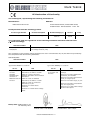
DN9650/DN9652
Network Bridge
Operator Manual
Midas Klark Teknik Limited,
Klark Industrial Park,
Walter Nash Road,
Kidderminster.
Worcestershire.
DY11 7HJ.
England.
Tel: +44 1562 741515
Fax: +44 1562 745371
Email: [email protected]
Website: www.klarkteknik.com
DN9650/DN9652 Network Bridge — Operator Manual
DOC02-DN9650/52 Issue A — February 2011
© Red Chip Company Ltd.
In line with the company’s policy of continual improvement, specifications and function may be
subject to change without notice. This Operator Manual was correct at the time of writing. E&OE.
IMPORTANT SAFETY INSTRUCTIONS
The lightning flash with arrowhead symbol within an equilateral triangle is
intended to alert the user to the presence of uninsulated “dangerous voltage”
within the product's enclosure that may be of sufficient magnitude to constitute a
risk of electric shock to persons.
The exclamation point within an equilateral triangle is intended to alert the user
to the presence of important operating and maintenance (servicing) instructions
in the literature accompanying the product.
1
Read these instructions.
2
Keep these instructions.
3
Heed all warnings.
4
Follow all instructions.
5
Do not use this apparatus near water.
6
Clean only with a dry cloth.
7
Do not block any of the ventilation
openings. Install in accordance with the
manufacturer’s instructions.
8
Do not install near any heat sources such
as radiators, heat registers, stoves, or
other apparatus (including amplifiers) that
produce heat.
9
Do not defeat the safety purpose of the
polarized or grounding-type plug. A
polarized plug has two blades with one
wider than the other. A grounding type
plug has two blades and a third grounding
prong. The wide blade or the third prong
are provided for your safety. If the
provided plug does not fit into your outlet,
consult an electrician for replacement of
the obsolete outlet.
10 Protect the power cord from being walked
on or pinched particularly at plugs,
convenience receptacles and the point
where they exit from the apparatus.
11 Only use attachments/accessories
specified by the manufacturer.
12 Unplug this apparatus during lightning
storms or when unused for long periods of
time.
13 Refer all servicing to qualified personnel.
Servicing is required when the apparatus
has been damaged in any way, such as
power-supply cord or plug is damaged,
liquid has been spilled or objects have
fallen into the apparatus, the apparatus
has been exposed to rain or moisture,
does not operate normally, or has been
dropped.
14 Use the mains plug to disconnect the
apparatus from the mains.
15 Warning: To reduce the risk of fire or
electric shock, do not expose this
apparatus to rain or moisture.
16 Warning: Do not expose this
equipment to dripping or splashing
and ensure that no objects filled with
liquids, such as vases, are placed on
the equipment.
17 Warning: The mains plug of the power
supply cord shall remain readily
operable.
INSTRUCTIONS DE SÉCURITÉ IMPORTANTES
Le symbole représentant un éclair fléché dans un triangle équilatéral a pour but
d'alerter l'utilisateur de la présence d'une "tension dangereuse" non isolée à
l'intérieur du boîtier, pouvant être d'une force suffisante pour constituer un risque
d'électrocution.
Le point d'exclamation dans un triangle équilatéral a pour but d'alerter
l'utilisateur de la présence d'instructions importantes concernant le
fonctionnement et la maintenance, dans la documentation qui accompagne
l'appareil.
1
Veuillez lire ces instructions.
2
Conservez ces instructions.
3
Respectez toutes les consignes de
sécurité.
4
Suivez scrupuleusement toutes les
instructions.
5
N'utilisez pas cet appareil près d'un point
d'eau.
6
Utilisez uniquement un chiffon sec pour le
nettoyer.
7
N'obstruez aucune des ouïes de
ventilation. Installez-le en respectant les
instructions du fabricant.
8
Ne l'installez pas près de sources de
chaleur tels que radiateurs, panneaux
chauffants, étuves, ou autres appareils
produisant de la chaleur (dont les
amplificateurs).
9
Ne pas utiliser d'adaptateur pour
supprimer la prise de terre des prises à
trois fiches. Si la prise fournie ne peut pas
être branchée dans la prise électrique,
adressez-vous à un électricen qui
remplacera la prise obsolète.
10 Protégez le cordon secteur afin que l'on ne
marche pas dessus et qu'il ne soit pas
pincé, surtout au niveau des prises, ou à
l'endroit où il sort de l'appareil.
11 Utilisez exclusivement des fixations et des
accessoires recommandés par le fabricant.
12 Débranchez l'appareil en période d'orage
ou s'il doit rester inutilisé pendant
longtemps.
13 Confiez toutes les réparations et
interventions à un personnel qualifié. Une
intervention est nécessaire si l'appareil a
été endommagé d'une façon ou d'une
autre, si son cordon ou sa prise secteur
ont été endommagés, si du liquide a été
renversé ou si des objets sont tombés à
l'intérieur, ou encore si l'appareil a été
exposé à la pluie ou à l'humidité, s'il ne
fonctionne pas normalement, ou s'il est
tombé.
14 Débrancher l'appareil du réseau électrique
par la prise de secteur.
15 Avertissement : afin de réduire le
risque d'incendie ou de choc
électrique, ne pas exposer cet
appareil à la pluie ou à de l'humidité.
16 Avertissement : n'exposez pas cet
équipement aux éclaboussures et
veillez à ce qu'aucun récipient rempli
de liquide, verre ou vase, ne soit posé
dessus.
17 Avertissement : la prise secteur doit
toujours rester directement
accessible.
EC-Declaration of Conformity
Klark Teknik
EC-Declaration of Conformity
The undersigned, representing the following manufacturer
Manufacturer:
Address:
Midas Klark Teknik Ltd.
Klark Industrial Park, Walter Nash Road,
Kidderminster. Worcestershire. DY11 7HJ.
hereby declares that the following product
Product Type Number
Product Description
Nominal Voltage(s)
Current
Freq.
DN9650
Network Bridge
115V AC
230V AC
218mA
123mA
50/60Hz
is in conformity with the regulations of the following marked EC-directives and bears the
-mark accordingly
reference number
title
2004/108/EC
EMC Directive (EMC)
2006/95/EC
Low-Voltage Directive (LVD)
The conformity of the product with EC directives for use in environments E1, E2, E3 and E4 is provided by
the compliance with the following standards:
Standards/date:
reference number
EN 60065:2002
title
Audio, video and similar electronic apparatus. Safety requirements.
Applied EMC emission test standards:
Applied EMC immunity test standards:
w
ref. no.
title
ref. no.
FCC/CFR 47; Part
15:2008
ANSI C63.4:2003, Class A: Radiated
disturbance, 30.0MHz to 2.0GHz
Canadian
Standard ICES003:Issue 4
CISPR 22: 1997 inc A2:2003:
Radiated disturbance and conducted
disturbance
title
EN 55024:1998
inc A1:2001 and
A2:2003
EN55022:2006 inc CISPR 22: Class A: Radiated
A1:2007
disturbance, 30.0MHz to 1.0GHz
CISPR 22: Class A: Conducted
disturbance, ac port
EN 61000-3-2:2006: Mains
harmonics
EN 61000-3-3:2008: Mains voltage
flicker
EN 61000-4-2:1995 Electrostatic
discharge
EN 61000-4-3:1996: Radiated RF
disturbance, 80-1000MHz
EN 61000-4-4:1995: Fast transient
bursts, ac & signal ports
EN 61000-4-5:1995: Surge, ac port
EN 61000-4-6:1996: Conducted RF
field, ac & signal ports
EN 61000-4-11:1994: Mains voltage
dips and interruptions
Place, date: Kidderminster, UK
7th February 2011
SVP, Midas Klark Teknik
Printed name: John Oakley
DOC04-DN9650ECDOC Rev. A
AVP, Product Development
Printed name: Alex Cooper
EC-Declaration of Conformity
Klark Teknik
EC-Declaration of Conformity
The undersigned, representing the following manufacturer
Manufacturer:
Address:
Midas Klark Teknik Ltd.
Klark Industrial Park, Walter Nash Road,
Kidderminster. Worcestershire. DY11 7HJ.
hereby declares that the following product
Product Type Number
Product Description
Nominal Voltage(s)
Current
Freq.
DN9652
Dual Network Bridge
115V AC
230V AC
252mA
138mA
50/60Hz
is in conformity with the regulations of the following marked EC-directives and bears the
-mark accordingly
reference number
title
2004/108/EC
EMC Directive (EMC)
2006/95/EC
Low-Voltage Directive (LVD)
The conformity of the product with EC directives for use in environments E1, E2, E3 and E4 is provided by
the compliance with the following standards:
Standards/date:
reference number
EN 60065:2002
title
Audio, video and similar electronic apparatus. Safety requirements.
Applied EMC immunity test standards:
Applied EMC emission test standards:
w
ref. no.
title
ref. no.
FCC/CFR 47; Part
15:2008
ANSI C63.4:2003, Class A: Radiated
disturbance, 30.0MHz to 2.0GHz
Canadian
Standard ICES003:Issue 4
CISPR 22: 1997 inc A2:2003:
Radiated disturbance and conducted
disturbance
EN 55024:1998
inc A1 & A2
EN55022:2006 inc CISPR 22: Class A: Radiated
A1:2007
disturbance, 30.0MHz to 1.0GHz
CISPR 22: Class A: Conducted
disturbance, ac port
EN 61000-3-2:2006: Mains
harmonics
EN 61000-3-3:2008: Mains voltage
flicker
title
EN 61000-4-2:1995 Electrostatic
discharge
EN 61000-4-3:1996: Radiated RF
disturbance, 80-1000MHz
EN 61000-4-4:1995: Fast transient
bursts, ac & signal ports
EN 61000-4-5:1995: Surge, ac port
EN 61000-4-6:1996: Conducted RF
field, ac & signal ports
EN 61000-4-11:1994: Mains voltage
dips and interruptions
Place, date: Kidderminster, UK
7th February 2011
SVP, Midas Klark Teknik
Printed name: John Oakley
DOC04-DN9652ECDOC Rev. A
AVP, Product Development
Printed name: Alex Cooper
Licences
The following are the license agreements applicable to this equipment.
End-User Licence Agreement for Midas™ and Klark Teknik™ Software
IMPORTANT - Please read this document carefully before using this Midas™ or
Klark Teknik™ Product. This is an agreement governing your use of software or
other machine instructions already installed on this Midas™ or Klark Teknik™
Product, as well as other software that we provide for installation on this Product.
The Midas™ or Klark Teknik™ Product will not operate in accordance with its
documentation without this software.
THIS AGREEMENT ("AGREEMENT" OR "LICENCE") STATES THE TERMS AND CONDITIONS UPON WHICH
MIDAS KLARK TEKNIK LIMITED ("COMPANY") OFFERS TO LICENSE THE INSTALLED FIRMWARE,
SOFTWARE AND/OR PROGRAMS ("the SOFTWARE") WITH THE MIDAS™ OR KLARK TEKNIK™ CONSOLE
OR SIGNAL PROCESSING PRODUCT ("PRODUCT") IN WHICH IT HAS BEEN INSTALLED BY, OR FOR
WHICH IT IS PROVIDED BY, THE COMPANY. BY USING THIS PRODUCT YOU WILL BE AGREEING TO
BECOME BOUND BY THE TERMS OF THIS LICENCE. IF YOU DO NOT AGREE TO THE TERMS OF THIS
LICENCE, DO NOT USE THIS PRODUCT AND PROMPTLY RETURN THE PRODUCT TO THE PLACE WHERE
YOU OBTAINED IT FOR A FULL REFUND. You agree to notify any persons whom you permit to operate
this Product of the terms of this Licence, and to require them to comply with these terms.
The Software is licensed, not sold, to you for use only under the terms of this Licence, and the
Company reserves all rights not expressly granted to you. The Company retains ownership of all copies
of the Software itself, and all proprietary parts of it, including those stored on or in the Product.
1. Licence: Subject to the terms and conditions of this agreement, the Company grants you, and
other persons you permit to operate the Product, a personal, limited, non-exclusive,
non-transferable licence to use the Software only on the single Product unit in which it has been
installed.
2. Restrictions: (a) The Software, and the accompanying written materials, are copyrighted and
contain trade secrets and other proprietary matter, including confidential information relating to
the specifications and performance characteristics of this Product. Save for such elements as
may be licensed to the Company, as described in paragraph 5, all rights to copyrights, trade
marks and trade secrets in the Software, or any modifications to it, are owned by the Company.
Unauthorised use or copying of the Company's proprietary Software, or any portion thereof, or
copying of those written materials, is prohibited. (b) You may not create, market, distribute, or
transfer copies of the Company's proprietary Software, or any part of it, to others, or duplicate,
rent, lease or loan that Software, or any part of it, except that you may transfer that Software
installed in this Product in conjunction with the sale, transfer, loan, rent or lease of this Product,
and subject at all times to this Licence. YOU MAY NOT REVERSE ENGINEER, DECOMPILE,
DISASSEMBLE, EXTRACT OR SEPARATE OUT, MODIFY, ADAPT, PORT, OR TRANSLATE THE
SOFTWARE, DERIVE THE SOURCE CODE OF THE SOFTWARE OR CREATE DERIVATIVE WORKS
BASED ON THE SOFTWARE OR ANY ACCOMPANYING WRITTEN MATERIALS, save as is allowed by
licences pertaining to component parts of the Software which are licensed by third parties, as
described under paragraph 5, or otherwise by law. (c) In the event you violate any term of this
Licence, all rights granted herein will automatically and immediately terminate and you must stop
using the Software and destroy any copies of the Software.
3. Limited Warranty: Subject to your installation of any Software updates issued by the Company
as described herein, and the condition below, the Company warrants that the Software will
operate in compliance with the Software's material specifications and documentation for a period
of 90 days from your purchase of this Product. The Software is provided "as is" and the Company
does not warrant that the operation of the Software will meet your requirements or operate free
from error. To the greatest extent permissible by law, the Company DISCLAIMS ALL
WARRANTIES AND CONDITIONS, EITHER EXPRESS OR IMPLIED, INCLUDING THE WARRANTIES
OF MERCHANTABILITY, FITNESS FOR A PARTICULAR PURPOSE, NON-INFRINGEMENT OF THIRD
PARTY RIGHTS OR CAPABILITY OF CORRECTLY PROCESSING PROVIDING AND/OR RECEIVING
DATE INFORMATION. You understand that the Company may update or revise the Software but
in so doing incurs no obligation to furnish such updates to you. However, the Company may in its
discretion make updates available from time to time upon such terms and conditions as it shall
determine. It is a condition of the above warranty that you install any such Software updates, as
may be issued from time to time by the Company for the Software, in accordance with the
Company's instructions, and if you do not do so such warranty will cease to apply. You may view
current Software updates at http://www.klarkteknik.com and http://www.midasconsoles.com.
4. Limited Liability: THE ENTIRE RISK ARISING OUT OF YOUR USE OR PERFORMANCE OF THE
SOFTWARE REMAINS WITH YOU. THE LIABILITY OF THE COMPANY FOR ANY CLAIMS ARISING
OUT OF THIS LICENCE AND/OR BASED UPON THE SOFTWARE, REGARDLESS OF THE FORM OF
ACTION, AND INCLUDING WORK STOPPAGE, PRODUCT FAILURE OF MALFUNCTION OR ANY
OTHER COMMERCIAL LOSS OR DAMAGE, SHALL NOT EXCEED THE COST OF THE LICENCE FEE
FOR THE SOFTWARE OR THE COST OF THIS PRODUCT. SUBJECT TO THE PROVISIONS OF
APPLICABLE LAW, IN NO EVENT SHALL THE COMPANY BE LIABLE FOR ANY LOSS OF DATA, LOST
OPPORTUNITY OR PROFITS, COST OF COVER OR SPECIAL, INCIDENTAL, CONSEQUENTIAL, OR
INDIRECT DAMAGES, EVEN IF YOU ADVISE THE COMPANY OF THE POSSIBILITY OF SUCH
DAMAGES. THIS IS A FUNDAMENTAL TERM OF THIS AGREEMENT AND YOU ACKNOWLEDGE
THAT THE AMOUNT YOU PAID FOR THE SOFTWARE AND/OR THE PRODUCT REFLECTS THIS
ALLOCATION OF RISK. NOTHING IN THIS PARAGRAPH PURPORTS TO EXCLUDE OR LIMIT THE
COMPANY'S LIABILITY FOR DEATH OR PERSONAL INJURY CAUSED BY NEGLIGENCE OR ANY
OTHER LIABILITY WHICH CANNOT BE EXCLUDED OR LIMITED BY LAW.
5. Other Third-Party Computer Programs: As referred to herein, the term "Software" refers
only to proprietary Midas™ or Klark Teknik™ software, owned by the Company, that has been
provided to you for installation on, or already installed in, a Product. In addition to the Software,
you may have also been provided, at no additional charge, with a version of the widely-available
GNU Linux Operating System, which is a modular operating system made up of hundreds of
individual software components, each of which was written, and the copyright and other rights in
which are owned individually, by various parties (collectively, "the GNU Linux Programs"). Each
component has its own applicable end user licence agreement, and many of these agreements
permit you to copy, modify, and redistribute the applicable software, but you must review the
on-line documentation that shares a directory or otherwise accompanies each of the GNU Linux
Programs provided to you for the specific terms and conditions. Nothing in this Licence limits
your rights under, or grants you rights that supersede, the terms of any other applicable end user
licence agreement. If you wish to receive a computer-readable copy of the source code for any
of the GNU Linux Programs that have been provided with your Midas™ or Klark Teknik™ Product,
send a cheque or money order (no cash accepted), your address and [£10.00] to cover the cost
of optical media, postage and handling, to:
Midas Klark Teknik Limited
ATTN: Linux Programs CD for Midas™/Klark Teknik™
Walter Nash Road,
Kidderminster.
Worcestershire.
DY11 7HJ.
England.
In your request, indicate your Product's name and model number, serial number and
version/release information. In your request, also indicate the relevant Software version/release
information. This offer, made pursuant to the GNU Linux Programs' end user licence agreements,
may expire according to the terms of those agreements, in which case your cheque will be
returned to you or destroyed at our option. Please note that the GNU Linux Programs that may
be available to you under this offer consists of the GNU Linux Operating System components only
and none of the proprietary application software developed by Midas or Klark Teknik is included.
Other updated Linux distributions containing application software are widely available from a
variety of Internet sources, and are often available at minimal or no cost.
6. Termination: This Licence will terminate immediately if you violate any of the Licence terms.
Upon termination you must discontinue use of the Software, and either destroy, erase or return
to Company all copies of the Software in your possession, custody or control, including those in
or on the Product.
7. General: This Licence constitutes the entire agreement between you and the Company with
respect to this Software and, save in the case of fraud, supersedes any other communication
(including advertising). Company reserves all rights not expressly granted to you in this licence.
If any provision of this Licence is held unenforceable, that provision shall be enforced to the
maximum extent permissible so as to give effect the intent of this Licence, and the remainder of
this Licence shall continue in full force and effect. This Licence shall be governed by English law
and the Courts of England and Wales will have exclusive jurisdiction to hear and decide any
dispute concerning it or its formation. No breach by you of any provision of this Licence shall be
waived or discharged except with the express written consent of the Company and no failure or
delay by the Company to exercise any of its rights under this Licence shall operate as a waiver
thereof and no single or partial exercise of any such right shall prevent any other or further
exercise of that or any other right. You acknowledge that the Company could be irreparably
damaged if the terms of this Licence were not specifically enforced, and agree that the Company
may seek appropriate equitable remedies with respect to breaches of this Licence, including
injunctive relief, in addition to such other remedies as the Company may otherwise have
available to it under applicable laws.
GNU General Public License (GPL)
For details of the Third Party Software License Attribution, Copyright and Terms and Conditions and
Notices, and the GNU LESSER GENERAL PUBLIC LICENSE and other public licenses, see the Midas
Digital Equipment GNU General Public License (GPL) Booklet part number DOC04-GPL .
Contents
Chapter 1
Getting Started. . . . . . . . . . . . . . . . . . . . . . . . . . . . . . . 1
Unpacking . . . . . . . . . . . . . . . . . . . . . . . . . . . . . . . . . . . . . . .
Installation . . . . . . . . . . . . . . . . . . . . . . . . . . . . . . . . . . . . . .
Handling the equipment . . . . . . . . . . . . . . . . . . . . . . . . . . .
Radio frequency interference - Class A device . . . . . . . . . . . .
Electric fields . . . . . . . . . . . . . . . . . . . . . . . . . . . . . . . . . . .
Connecting up the DN965X . . . . . . . . . . . . . . . . . . . . . . . . . . .
Powering the unit . . . . . . . . . . . . . . . . . . . . . . . . . . . . . . . . . .
Configuring the unit for the first time . . . . . . . . . . . . . . . . . . . .
Chapter 2
..
..
..
..
..
..
..
..
.
.
.
.
.
.
.
.
.
.
.
.
.
.
.
.
.1
.1
.2
.2
.2
.2
.3
.4
Overview . . . . . . . . . . . . . . . . . . . . . . . . . . . . . . . . . . . 7
About the DN965X units . . . . . . .
Key features . . . . . . . . . . . . . . .
Host software version and updates
Changing the network module . . .
About this manual . . . . . . . . . . .
Trademarks . . . . . . . . . . . . . . . .
Service and support . . . . . . . . . .
.
.
.
.
.
.
.
.
.
.
.
.
.
.
.
.
.
.
.
.
.
.
.
.
.
.
.
.
.
.
.
.
.
.
.
.
.
.
.
.
.
.
.
.
.
.
.
.
.
.
.
.
.
.
.
.
.
.
.
.
.
.
.
.
.
.
.
.
.
.
.
.
.
.
.
.
.
.
.
.
.
.
.
.
.
.
.
.
.
.
.
.
.
.
.
.
.
.
.
.
.
.
.
.
.
.
.
.
.
.
.
.
.
.
.
.
.
.
.
.
.
.
.
.
.
.
.
.
.
.
.
.
.
.
.
.
.
.
.
.
.
.
.
.
.
.
.
.
.
.
.
.
.
.
.
.
.
.
.
.
.
.
.
.
.
.
.
.
.
.
.
.
.
.
.
. .7
. .8
. .9
. .9
. 10
. 10
. 10
Chapter 3
Front Panel. . . . . . . . . . . . . . . . . . . . . . . . . . . . . . . . . 11
Chapter 4
Rear Panel . . . . . . . . . . . . . . . . . . . . . . . . . . . . . . . . . 15
Mains input . . . . . . . . . . . . . . . . . . . . . .
Clock section . . . . . . . . . . . . . . . . . . . . .
AES50 section (DN9650 only) . . . . . . . . .
CONTROL connector . . . . . . . . . . . . . . . .
Chapter 5
..
..
..
..
.
.
.
.
.
.
.
.
.
.
.
.
.
.
.
.
.
.
.
.
.
.
.
.
.
.
.
.
.
.
.
.
.
.
.
.
.
.
.
.
.
.
.
.
.
.
.
.
.
.
.
.
.
.
.
.
.
.
.
.
.
.
.
.
. 16
. 16
. 16
. 16
Configuring the DN965X . . . . . . . . . . . . . . . . . . . . . . 17
About DN965X configuration . . . . . . . . . . . . . .
About the web browser interface . . . . . . . . . . .
Changing the displayed text . . . . . . . . . . . . . .
Setting up a network module . . . . . . . . . . . . . .
Clocking options . . . . . . . . . . . . . . . . . . . . . . .
Ethernet IP Addressing . . . . . . . . . . . . . . . . . .
Updating the unit’s host software . . . . . . . . . . .
Chapter 6
.
.
.
.
....
....
....
....
....
....
....
.
.
.
.
.
.
.
.
.
.
.
.
.
.
.
.
.
.
.
.
.
.
.
.
.
.
.
.
.
.
.
.
.
.
.
.
.
.
.
.
.
.
.
.
.
.
.
.
.
.
.
.
.
.
.
.
.
.
.
.
.
.
.
.
.
.
.
.
.
.
.
.
.
.
.
.
.
. 17
. 17
. 19
. 19
. 20
. 21
. 22
Operation . . . . . . . . . . . . . . . . . . . . . . . . . . . . . . . . . . 25
Using a MADI module as a MADI split . . . . . . . . . . . . . . . . . . . . . . . . 25
Limitations . . . . . . . . . . . . . . . . . . . . . . . . . . . . . . . . . . . . . . . . 25
Appendix A
Technical Specification. . . . . . . . . . . . . . . . . . . . . . . . 27
Appendix B
Functional Block Diagrams. . . . . . . . . . . . . . . . . . . . . 29
DN9650
DN9652
DN9650 Network Bridge
Operator Manual
. . . . . . . . . . . . . . . . . . . . . . . . . . . . . . . . . . . . . . . . . . . . 30
. . . . . . . . . . . . . . . . . . . . . . . . . . . . . . . . . . . . . . . . . . . . 31
xiii
Contents
Appendix C
Service Information . . . . . . . . . . . . . . . . . . . . . . . . . 33
Restoring the factory defaults . . . .
Routine maintenance . . . . . . . . . .
Cleaning . . . . . . . . . . . . . . . . . . .
Checking/replacing the mains fuse
Special accessories . . . . . . . . . . .
Optional equipment . . . . . . . . . . .
Equipment disposal . . . . . . . . . . .
xiv
.
.
.
.
.
.
.
.
.
.
.
.
.
.
.
.
.
.
.
.
.
.
.
.
.
.
.
.
.
.
.
.
.
.
.
.
.
.
.
.
.
.
.
.
.
.
.
.
.
.
.
.
.
.
.
.
.
.
.
.
.
.
.
.
.
.
.
.
.
.
.
.
.
.
.
.
.
.
.
.
.
.
.
.
.
.
.
.
.
.
.
.
.
.
.
.
.
.
.
.
.
.
.
.
.
.
.
.
.
.
.
.
.
.
.
.
.
.
.
.
.
.
.
.
.
.
.
.
.
.
.
.
.
.
.
.
.
.
.
.
.
.
.
.
.
.
.
.
.
.
.
.
.
.
.
.
.
.
.
.
.
.
.
.
.
.
.
.
.
.
.
.
.
.
.
.33
.33
.33
.34
.34
.34
.34
DN9650 Network Bridge
Operator Manual
Chapter 1: Getting Started
This chapter shows you how to prepare the DN965X for operation, which includes:
•
Unpacking
•
Installation
•
Connecting up
•
Switching the unit on/off
•
Initial configuration
Before installing, setting up or operating this equipment, make sure you have
read and fully understand all of the “IMPORTANT SAFETY INSTRUCTIONS” at
the front of this document.
Important:
You must set up the IP address and netmask of your computer (PC/Mac)
before using it for the first time.
Unpacking
Carefully unpack your DN965X equipment package. Then, inspect the DN965X unit
carefully for any signs of damage that may have occurred during transit and notify the
courier immediately if you discover any.
Please retain the original packing in case you should need to return the equipment to
the manufacturer or supplier, or transport or ship the unit later.
Installation
When installing the unit, take the following into consideration.
•
Do not install the equipment in places of poor ventilation.
•
Do not install this equipment in a location subjected to excessive heat, dust or
mechanical vibration. Allow for adequate ventilation around the equipment, making
sure that its vents are not obstructed. To prevent excessive heating of the
equipment, avoid mounting it directly above power amplifiers or other devices that
radiate significant amounts of heat, such as radiators and heaters. Keep the
equipment out of direct sunlight.
•
This unit is designed for mounting in any 19” EIA standard rack. Four rack-mount
holes in the front panel are provided for rack mounting and are designed to fully
support the weight of the unit in the rack. Avoid over-tightening the rackmount
screws, as this could damage the front panel.
DN9650/DN9652 Network Bridge
Operator Manual
1
Chapter 1: Getting Started
Handling the equipment
Completely isolate the equipment electrically and disconnect all cables from the
equipment before moving it.
When lifting or moving the equipment, always take its size and weight into
consideration.
Radio frequency interference - Class A device
This equipment has been tested and found to comply with the limits for a Class A digital
device, pursuant to Part 15 of the FCC Rules. These limits are designed to provide
reasonable protection against harmful interference when the equipment is operated in a
commercial environment. This equipment generates, uses, and can radiate radio
frequency energy and, if not installed and used in accordance with the instruction
manual, may cause harmful interference to radio communications. Operation of this
equipment in a residential area is likely to cause harmful interference in which case the
user will be required to correct the interference at his own expense.
Electric fields
Caution:
In accordance with Part 15 of the FCC Rules & Regulations, “… changes or
modifications not expressly approved by the party responsible for compliance
could void the user's authority to operate the equipment.”
Should this product be used in an electromagnetic field that is amplitude modulated by
an audio frequency signal (20Hz to 20kHz), the signal to noise ratio may be degraded.
Degradation of up to 60dB at a frequency corresponding to the modulation signal may
be experienced under extreme conditions (3V/m, 90% modulation).
Connecting up the DN965X
Making sure that all equipment is switched off, connect the DN965X to the rest of your
audio equipment, as shown in the following diagrams.
Word clock target
Word clock source
Video black burst source
3-port AES50
DN9650 rear panel
AES50 connectors (for
example, on rear panel
of XL8)
Third party network
module
Network module A
Midas digital console (for
example, an XL8 control centre)
Typical DN9650 audio connection configuration
2
DN9650/DN9652 Network Bridge
Operator Manual
Powering the unit
Word clock target
Word clock source
Video black burst source
DN9652 rear panel
Third party network
module
Third party network
module
Network module A
Network module B
Typical DN9652 audio connection configuration
Powering the unit
This section shows you how to connect the unit to the mains, switch the unit on/off and
electrically isolate the unit.
The internal power supplies are of the switch mode type that automatically sense the
incoming mains voltage and will work where the nominal voltage is in the range
100VAC to 240VAC.
>> To switch the unit on/off
Making sure that the mains power at the power outlet is off, connect the mains cable
supplied with your DN965X to the mains power outlet and then to the mains socket at
the rear of your unit. To switch the unit on/off, use the mains on/off switch on the rear
of the unit. The blue KT roundel on the front of the unit will illuminate to show that
power is on.
To electrically isolate the unit, switch it off and remove the mains cable from mains IEC
socket on the rear panel.
DN9650/DN9652 Network Bridge
Operator Manual
3
Chapter 1: Getting Started
Configuring the unit for the first time
Important:
Before you use the unit for the first time, you must configure your computer
with the IP address and netmask to suit the range used by the DN965X.
Before you can use the DN965X as a network bridge, you must first configure it by
choosing the type of network module card(s) that are fitted in the unit and then setting
them up. Configuration involves connecting the DN965X to a computer running an
up-to-date web browser. To make sure your computer is compatible with the DN965X,
you will need to change its IP address and netmask. For more information on
configuration, see Chapter 5 "Configuring the DN965X" on page 17.
>> To connect the DN965X to a computer and then open its configuration
menu in the web browser
1
Connect an Ethernet cable to the CONTROL socket on the rear panel of the
DN965X and then to the Ethernet port of your computer.
Ethernet cable
Laptop PC/Mac
CONTROL
connector
Connecting a DN965X to a computer
2
Switch on the DN965X and your computer. (Note the default IP address of the
DN965X, which is displayed on its LCD screen during power up.)
3
To make sure your computer is compatible with the DN965X, we recommend that
you change the IP address and netmask of your computer to 192.168.2.1 and
255.255.0.0, respectively; for instructions, refer to your computer’s help and
support information.
4
Open your computer’s web browser.
Note: Make sure your web browser is up-to-date.
5
In the web browser’s address bar, type
in the following default IP address
(displayed on the unit’s LCD screen
during power up) and then press
ENTER:
“http://192.168.10.10”
Typical browser address bar
4
DN9650/DN9652 Network Bridge
Operator Manual
Configuring the unit for the first time
6
The DN965X NETWORK BRIDGE
CONFIGURATION menu will open in
the web browser’s Klark Teknik
DN965X Configuration tab.
>> To select which network card(s) are fitted in the unit
1
In the configuration menu, click
Change Module Type in the desired
network module section. If no network
module type has been set up, its
section will look similar to the one
shown right. On the DN9650, network
module B is always a Klark Teknik
3-Port AES50 Module.
For details of which network module section on the configuration menu applies
which network module card fitted in the rear panel of the unit, see Figure 2
“Typical configuration menu” on page 18 and Figure 1 “Rear panel of the
DN965X” on page 15.
2
In the Change Network Module
Type window, select the appropriate
network module type and then click
OK.
3
Your DN965X is now ready for use as a network bridge. However, if you want to
change the settings of the network module cards, see “Setting up a network
module” on page 19
DN9650/DN9652 Network Bridge
Operator Manual
5
Chapter 1: Getting Started
6
DN9650/DN9652 Network Bridge
Operator Manual
Chapter 2: Overview
Thank you for purchasing a Klark Teknik DN9650/DN9652 Network Bridge. The
DN965X is a user-friendly, high-performance, digital audio network bridge.
Both the DN9650 and DN9652 units compliment each other. The DN9650 allows
AES50-equipped Midas digital systems, such as the XL8 and PRO6, and Klark Teknik
DN9696 High Resolution Audio Recorders to connect to third party multi-channel digital
audio networks, while the DN9652 allows two dissimilar digital audio networks to
interface simply and reliably.
Your DN965X was conceived by Klark Teknik to offer audio professionals
high-performance audio equipment, designed to provide no-compromise sonic quality
with a feature set that offers all essential facilities and functions. It represents the very
best of British design and engineering combined with contemporary, efficient
manufacturing methods, and will give you many years of reliable service.
All this is backed up, of course, by the standard Klark Teknik three year warranty.
Please take the time to complete and return the registration card or fill in the Warranty
Registration Form online by visiting our website at www.klarkteknik.com and, to obtain
the best results with a minimum of effort, also read this operator manual.
Finally, enjoy your Klark Teknik Network Bridge!
About the DN965X units
The DN965X units provide bi-directional sample rate conversion of 24-bit resolution
digital audio between two clock domains, all in a standard 1U high 19” rack mount
chassis.
Front and rear panels of the DN9650 Network Bridge
The DN9650 has an AES50 and a network clock domain, provided by a three-port
AES50 digital audio interface and a third party network module interface, whereas both
clock domains of the DN9652 are of the network type and are provided by two, third
party network module interfaces.
Supported network modules are designed and manufactured by Lab X Technologies and
Audinate Pty Ltd. and conform to Cirrus Logic Inc. CM-1/CM-2 interface to support
protocols, which include MADI, Audinate Dante and Aviom A-Net.
DN9650/DN9652 Network Bridge
Operator Manual
7
Chapter 2: Overview
Front and rear panels of the DN9652 Network Bridge
Since the network clock domains (A and B) contain digital audio, an intermediate
asynchronous sample rate converter (ASRC) effectively resamples the audio as it
passes between them, while obeying Nyquist sampling theory1. The ASRC has a bypass
option for when both domains are locked to the same sample clock; this has the facility
to select one of the clock domains as a master, which allows one to be synchronously
clocked from the other to minimise latency.
•
AES50 clock domain Supports either internal or external synchronisation. The
DN9650 uses its on-board clock oscillator for internal synchronisation. For external
synchronisation, the incoming clock is connected to one of the AES50 ports.
Additionally, the AES50 clock domain has the option of slaving to the network clock
domain, word clock and video black burst if the SRC is bypassed.
•
Network clock domain Supports clock synchronisation to the incoming clock via
a third party network module, word clock in or video black burst (supporting
PAL/NTSC formats) interfaces. Additionally (DN9650 only), the network clock
domain has the option of slaving to the AES50 clock domain.
Supported third party multi-channel digital audio interfaces are as follows:
•
LabX MADI V1.14
•
Audinate Dante
•
Aviom a-Net
•
Ethersound
•
It is intended that more third party protocols will be supported
The DN965X has an internal Linux web server running a platform-independent
HTML-based interface that allows unit configuration via a computer (with up-to-date
browser), which is connected to the Ethernet port on the rear panel of the unit.
Supported platforms are: PCs (Windows); Apple Macs; and Linux-based PCs.
The units are capable of operating from a 100 to 240V ±10%, 50 to 60Hz AC power
source.
Key features
The DN965X has the following key features:
•
1U high, 19” rackmount unit.
•
Able to interface between AES50 and third party multi-channel audio networks
(DN9650 only) or dual networks (DN9652 only).
1. The Nyquist sampling theory defines the process of sampling audio within a digital system.
8
DN9650/DN9652 Network Bridge
Operator Manual
Host software version and updates
•
Supports up to 64 bi-directional channels of 24-bit, 96kHz audio per network or
AES50 port (DN9650 only) with 1:1 channel mapping.
•
Supports operation at 48kHz and 96kHz sampling frequencies. Bi-directional ASRC
on every channel with bypass facility to isolate network domains.
•
High channel count asynchronous sample rate conversion (ASRC).
•
Platform-independent web browser configuration interface software hosted on
integrated Linux web server.
•
Ethernet port for remote computer connection (unit configuration and software
updating).
•
Ultra-high stability reference - grade 1 part per million (1 ppm) temperaturecontrolled clock oscillator.
•
User-selectable stop output clock facility if input clock fails to function, to propagate
network failure across ASRC for automatic or manual redundancy switchover.
•
Flexible third party interface clock synchronisation options:
•
•
Network module incoming and outgoing clocks.
•
Word clock input.
•
Word clock output.
•
Video black burst in (PAL/SECAM/NTSC formats in standard definition (SD) and
high definition (HD) resolutions).
Clock Synchronisation:
•
Clock synchronisation scheme divided into two network domains, separated by
the ASRC, and either domain can be selected as clock master;
•
AES50 clock source (DN9650 only) may be internal or external (incoming AES50
clock, word clock and video black burst);
•
Network clock source may be incoming network module clock, word clock in or
video black burst in.
•
100V-240V universal power supply, 50Hz to 60Hz.
•
Upgradeability.
Host software version and updates
This manual is for DN9650 and DN9652 units running host software version 1.00 and
later.
An Ethernet Control port is provided on the rear panel to facilitate software updates.
Changing the network module
Both CM-1 and CM-2 network modules must only be changed by qualified service
personnel. Contact Midas Klark Teknik Limited for details.
DN9650/DN9652 Network Bridge
Operator Manual
9
Chapter 2: Overview
About this manual
This is the operator manual for the DN9650 and DN9652 Network Bridge units. It is
intended to help get your units installed and in operation as quickly as possible by
giving you unpacking, installation, connection, configuration and setting up instructions.
To help familiarise you with the units, there is a description of the front and rear panels,
along with easy-to-follow user instructions.
When referring to both DN9650 and DN9652 type units you will see “DN965X”. Any
information applying only to one type of unit will include the name of the unit.
Trademarks
Mac and the Mac logo are trademarks of Apple Inc., registered in the U.S. and other
countries.
Microsoft and Windows are registered trademarks of Microsoft Corporation in the United
States and other countries.
Service and support
We provide superb levels of support and service to give users confidence in Klark Teknik
products. For more information, please contact your local distributor or Klark Teknik at
the address shown in the front of this manual.
10
DN9650/DN9652 Network Bridge
Operator Manual
Chapter 3: Front Panel
This chapter describes the front panel of the DN9650 and DN9652 units, which
comprise the following.
3
1
2
4
5
6
5
Front panel of the DN9650 (top) and DN9652 (bottom)
Item
Description
Illustration
1
Ventilation grill Air intake for internal
cooling via an internal fan. Do not obstruct.
N/A
2
CONTROL section A green ETHERNET LED
illuminates to show the communication status
between unit and PC, as follows:
3
4
•
Illuminated = traffic detected.
•
Extinguished = no traffic detected.
AES50 AUDIO section (DN9650 only)
Three sets of LEDs provide status information
for the three AES50 audio connectors. The
green OK and red ERROR LEDs per set show
the following:
•
Pulsating green with red extinguished =
synchronised and with audio activity.
•
Green extinguished with red illuminated =
loss of synchronisation and no audio
activity.
ASYNCHRONOUS SAMPLE RATE
CONVERTER section (DN9650 only) This
section shows the status of the configured
clock source, which can be AES50 output,
ASRC or network output. Each source has a
yellow ENABLED LED, which illuminates to
show that the source is enabled. The DN9650
also has the facility to stop the output clock if
the input clock fails. This condition is indicated
by the illumination of the red STOPPED LED.
For the LED status, see Table 1 “DN9650 ASRC
LED status” on page 13.
DN9650/DN9652 Network Bridge
Operator Manual
11
7
8
9
Chapter 3: Front Panel
Item
Description
5
NETWORK section This section shows the
status of the network module connection, as
follows:
6
Illustration
•
Constantly illuminated green with red
extinguished = cable/fibre is synchronised,
but there is no audio activity.
•
Pulsating green with red extinguished =
cable/fibre is on with audio activity.
•
Green extinguished with red illuminated =
cable/fibre are off.
ASYNCHRONOUS SAMPLE RATE
CONVERTER section (DN9652 only) This
section shows the status of the configured
clock source, which can be ASRC or network
output. Each source has a yellow ENABLED
LED, which illuminates to show that the source
is enabled. The DN9652 also has the facility to
stop the output clock if the input clock fails.
This condition is indicated by the illumination of
the red STOPPED LED.
For the LED status, see Table 2 “DN9652 ASRC
LED status” on page 13.
7
LCD display This backlit, alphanumeric
display has two rows of 16 digits. During boot
up the display shows the unit’s current
IP address and subnet mask for about five
seconds and then the user-configured text
thereafter.
8
Klark Teknik roundel Has a blue backlight,
which illuminates to show that power is on.
9
Cut-out There are four cut-outs for rack
mount fixings.
12
N/A
DN9650/DN9652 Network Bridge
Operator Manual
Front panel
Table 1: DN9650 ASRC LED status
AES50 OUTPUT
LEDs
ASRC
ENABLED
LED
NETWORK OUTPUT
LEDs
Status
Yellow LED = off
Red LED = off
Off
Yellow LED = off
Red LED = off
When ASRC is disabled, AES50
and network output indication
does not play any role.
Yellow LED = on
Red LED = off
On
Any condition
The network clock output is
working. The AES50 output
clock is let onto the ASRC
AES50 clock input.
Yellow LED = on
Red LED = on
On
Any condition
The network clock output is not
working. The AES50 output
clock is stopped (and the ASRC
AES50 clock input is disabled).
Any condition
On
Yellow LED = on
Red LED = off
The AES50 clock output is
working. The network output
clock is let onto the ASRC
network clock input.
Any condition
On
Yellow LED = on
Red LED = on
The AES50 clock output is not
working. The MADI output
clock is stopped (and the ASRC
network clock input is
disabled).
Table 2: DN9652 ASRC LED status
NETWORK B
OUTPUT LEDs
ASRC
ENABLED
LED
NETWORK A
OUTPUT LEDs
Status
Yellow LED = off
Red LED = off
Off
Yellow LED = off
Red LED = off
When ASRC is disabled,
network output indication does
not play any role.
Yellow LED = on
Red LED = off
On
Any condition
The network B clock output is
working. The network A
output clock is let onto the
ASRC network B clock input.
Yellow LED = on
Red LED = on
On
Any condition
The network B clock output is
not working. The network A
output clock is stopped (and
the ASRC network B clock input
is disabled).
Any condition
On
Yellow LED = on
Red LED = off
The network B clock output is
working. The network A output
clock is let onto the ASRC
network A clock input.
Any condition
On
Yellow LED = on
Red LED = on
The network B clock output is
not working. The MADI output
clock is stopped (and the ASRC
network A clock input is
disabled).
DN9650/DN9652 Network Bridge
Operator Manual
13
Chapter 3: Front Panel
14
DN9650/DN9652 Network Bridge
Operator Manual
Chapter 4: Rear Panel
This chapter describes the rear panel of the DN9650 and DN9652 units, which comprise
the following.
6
DN9650
1
2
3
4
5
3
7
DN9652
Figure 1: Rear panel of the DN965X
Item
Description
1
Ventilation grill
2
Mains input section
3
Network module section Each network module section contains a
replaceable network module.
Air outtake for internal fan cooling. Do not obstruct.
(see “Mains input” on page 16).
Network modules should only be replaced by approved service
personnel.
4
Clock section
5
RESET button This white, square, recessed reset button
restores the unit to its default condition. To activate the
button, press and hold for about five seconds.
6
AES50 section
7
CONTROL connector
DN9650/DN9652 Network Bridge
Operator Manual
(see “Clock section” on page 16).
(see “AES50 section (DN9650 only)” on page 16).
(see “CONTROL connector” on page 16).
15
Chapter 4: Rear Panel
Mains input
Always replace the mains fuse with one of the same type and rating, as
printed underneath the fuse drawer.
The mains input section has a mains IEC
socket, mains fuse compartment and
on/off switch. Printed underneath is the
mains supply voltage and fuse
specifications.
Mains IEC socket
Mains fuse compartment
Mains on/off switch
The mains input is an auto-voltage
sensing switch mode power supply that
operates where normal mains voltage is in
the range 100V AC to 240V AC.
Supply voltage and fuse information
Clock section
This section provides 75 ohm connections for
two types of external clock for synchronisation:
•
BLACK BURST 75R A single INPUT
socket provides connection for a video
signal generator.
•
WORD CLOCK 75R An OUTPUT socket
and an INPUT socket provide connection
for an external word clock source.
BNC chassis connectors
AES50 section (DN9650 only)
The AES50 section of the DN9650 has three
EtherCon® XLR chassis connectors for audio
connections to/from a Midas digital system or
AES-equipped device.
Each connector supports 24 bi-directional
channels operating at a fixed sampling
frequency of 96kHz for compatibility with
existing Midas and Klark Teknik
AES50-equipped products.
EtherCon® XLR connectors
CONTROL connector
A single EtherCon® XLR chassis connector lets you connect to a
computer to enable unit configuration and software upgrade.
16
DN9650/DN9652 Network Bridge
Operator Manual
Chapter 5: Configuring the DN965X
This chapter shows you how to configure the DN965X. Although this chapter uses the
DN9650 as an example, the procedures also apply to the DN9652 unless stated
otherwise.
About DN965X configuration
The DN965X is configured via a simple menu-driven user interface (configuration
menu) operating in a web browser on a computer, such as a laptop PC or Mac, which is
akin to setting up a router. The supporting software is hosted in a Linux-based web
server inside the DN965X.
DN965X configuration lets you do the following:
•
Change the text displayed in the LCD display on the front panel of the unit (see
“Changing the displayed text” on page 19).
•
Set up the network module(s) and, on the DN9650 only, the 3-port AES50 module
(see “Setting up a network module” on page 19).
•
Configure the clocking options (see “Clocking options” on page 20).
•
Set up the IP address of the DN965X for Ethernet networking (see “Ethernet IP
Addressing” on page 21).
•
Update the host software of the DN965X (see “Updating the unit’s host software” on
page 22).
To configure your DN965X you will need a standard Ethernet cable and a computer with
an up-to-date web browser. For more information, see “To connect the DN965X to a
computer and then open its configuration menu in the web browser” on page 4.
About the web browser interface
Supported operating systems and HTTP-compliant web browsers include the following:
•
PC Windows XP, Windows 7 with Internet Explorer, Mozilla® Firefox®, Google
Chrome™.
•
Mac OS X 10.5 Leopard, OS X 10.6 Snow Leopard with Apple Safari, Mozilla®
Firefox®, Google Chrome™.
DN9650/DN9652 Network Bridge
Operator Manual
17
Chapter 5: Configuring the DN965X
1
3
2
4
5
6
7
8
Figure 2: Typical configuration menu
Item
Screen element
1
Unit type and title of web page.
2
Status A view-only section that shows the communication status of the
network module(s) and/or the three AES50 audio ports.
3
Front Panel Shows the current display of the LCD screen (DN965X front
panel) and lets you change it.
4
Network A module panel Shows the parameters of the currently fitted
network module in position A and lets you change its type and settings.
5
Network B module panel Shows the parameters of the currently fitted
network/3-port AES50 (DN9650 only) module in position B and lets you
change its type and settings.
6
Clocking Options Shows the configuration details of the clock and lets
you change its settings.
7
IP Address Shows the current IP address and netmask and lets you
change them.
8
Unit Software Shows the current version of the unit’s host software and
lets you perform an upgrade.
18
DN9650/DN9652 Network Bridge
Operator Manual
Changing the displayed text
Changing the displayed text
The LCD display has two rows (lines) of 16 characters that support ASCII characters.
>> To change the text displayed on the DN965X’s LCD screen
1
In the Front Panel section of the configuration window, click Change LCD Text.
LCD display on front
panel of DN965X
2
In the Line 1 field of the Change LCD Text window, type in the desired text.
The default display shows the unit type.
3
In the Line 2 field, type in the desired text. The default display shows the unit
name.
4
Click OK.
Setting up a network module
After initially setting up the type of each network module fitted in the DN965X (see “To
select which network card(s) are fitted in the unit” on page 5), you can then configure
their settings, such as clock source and sample frequency.
Note: On some network module cards, it may not be possible to set them up via the
configuration menu of the DN965X.
>> To configure a network module card
1
In the desired network module section,
click Change Module Settings. For
example, in the Lab X MADIX MADI
Module section.
If a network module card cannot be
configured via the configuration menu,
text in its Network Module section
will inform you of this.
DN9650/DN9652 Network Bridge
Operator Manual
19
Chapter 5: Configuring the DN965X
2
In the Change XXX Module Settings
window, choose the desired options.
For example, select the sample
frequency as 96kHz and the clock
source as MADI Clock (Slave) for a Lab
X MADIX MADI module.
3
Click OK.
>> To change the settings of a Klark Teknik 3-Port AES50 Module card
(DN9650 only)
The 3-port AES50 module card is configured in the same way as a network module card
(see “To configure a network module card” on page 19).
Clocking options
The Change Clocking Options window lets you set parameters such as enabling the
ASRC, selecting the word clock output source, setting the VBB format, etc.
>> To change the clocking options of a network module
1
In the Clocking Options section of the configuration window, click Change
Clocking Options.
2
In the Change Clocking Options window (example shows a Lab X MADIX MADI
Module card), choose the desired options.
3
Click OK.
20
DN9650/DN9652 Network Bridge
Operator Manual
Ethernet IP Addressing
Ethernet IP Addressing
The IP address (default 192.168.10.10) can be changed via the configuration menu to
allow operation as part of an Ethernet network. The default netmask value is
255.255.0.0, but you can also modify this if you want.
>> To change the IP address of the DN965X
1
In the IP Address section of the configuration window, click Change IP
Address.
2
In the New IP Address after reboot field of the Change IP Address window,
type in the desired IP address. The range is 0.0.0.0 to 254.254.254.254.
3
In the New Netmask after reboot field, type in the desired netmask. The
range is 0.0.0.0 to 255.255.255.255.
Note: If you change the netmask, you will have to reconfigure your computer’s
IP address/netmask.
4
Click OK. The Change IP Address window will close. The IP Address section
of the configuration window will now display a new field, which informs yo what
the new IP address will be after reboot. (This field will disappear after a reboot.)
Temporary IP address field
5
For the new IP address and netmask to come into effect, reboot the DN965X by
switching it off and then on again. (The new IP address will be displayed during
startup.)
6
To reconnect to the configuration web page you will need to type in the new
IP address in the browser’s address (see “To connect the DN965X to a computer
and then open its configuration menu in the web browser” on page 4).
If you have changed the subnet, you will also have to reconfigure your
computer’s IP address/subnet mask.
DN9650/DN9652 Network Bridge
Operator Manual
21
Chapter 5: Configuring the DN965X
Updating the unit’s host software
The upgrade procedure involves transferring a number of files individually to the
DN965X unit. The files are supplied in a single TAR file. Before you can begin the
upgrade these files must be ‘unzipped’ to a location that is easily accessible from your
computer.
The TAR file will contain all of the files required to update any type of unit, as listed in
the following table, which also shows the recommended order of upload. Although this
order is not critical, it is important that you upload the 9650apps.img file last, as this
file triggers a reboot of the DN965X unit.
Table 3: TAR files and recommended file upload order
Recommended upload order
Filename
DN9650
DN9652
9650_ramdisk.gz
1
1
unmanagedredboot.bin
2
2
vmlinux26.bin
3
3
fpgas/dn9650_asrc.bin
4
4
fpgas/dn9650_bridge.bin
5
N/A
fpgas/dn9652_bridge.bin
N/A
5
9650apps.img
6
6
>> To update the host software of the DN965X
Do not switch the unit off during the software update procedure.
1
In the Unit Software section of the configuration window, click Update
Software.
2
In the Update Software window, select the update file (see Table 3 “TAR files
and recommended file upload order” on page 22).
You can locate the file by using the browse facility. Click Browse and navigate to
the file you want, then select the file.
22
DN9650/DN9652 Network Bridge
Operator Manual
Updating the unit’s host software
3
With the desired file displayed in the Choose Update File field, click OK. The
Updating window will open, showing that the update is in progress.
4
When the file has been updated you should see an Upgrade successfully
transferred message (typically as shown below). Click the Click here to
return to the main page link to go back to the configuration page.
However, if you see the following No file was uploaded message, you have
probably selected an invalid update file. Click the Click here to return to the
main page link to go back to the configuration page and try again.
5
Repeat steps 1 to 4 for the remaining files, except the ‘apps’ file (see Table 3
“TAR files and recommended file upload order” on page 22).
6
You are now ready to update the ‘apps’ file. Repeat steps 1 to 4. You should see
the Upgrade successfully transferred message. However, this does not mean
that the upgrade is complete!
You must wait until the unit has fully rebooted before operating it.
DN9650/DN9652 Network Bridge
Operator Manual
23
Chapter 5: Configuring the DN965X
The unit will automatically reboot to apply the changes. At this point you must
monitor the reboot progress on the LCD display screen, which will show
the following messages, finally displaying the default. Note the IP address
during the reboot.
Default IP address
Default display
7
When the default display appears, the DN965X has fully rebooted and it should
now be fully updated with the new software. Click the Click here to return to
the main page link on the to go back to the configuration page. Make sure that
the unit has been updated by checking the software version in the Unit
Software section.
If you cannot get back to the configuration page, try typing in the IP address you
saw at reboot (see “To connect the DN965X to a computer and then open its
configuration menu in the web browser” on page 4).
8
Your unit should now be fully upgraded and ready for operation.
24
DN9650/DN9652 Network Bridge
Operator Manual
Chapter 6: Operation
Although there are no operating procedures associated with the DN965X, this chapter
shows you how to create a MADI split.
Using a MADI module as a MADI split
One of the features of the MADI card is that it allows you to create a MADI split. This is
because the MADI card has both optical and co-axial connections, which can both be
enabled simultaneously in the software (see “Setting up a network module” on
page 19). This allows outgoing audio from the DN965x to be received simultaneously
on both remote systems. However, this configuration has some very real limitations as
compared to a real split (see “Limitations” on page 25).
MADI device (slave)
Fibre optic cables
Tx
Coaxial cable
Rx
MADI device (slave)
Tx
Typical example of a DN9650/DN9652 connected in a MADI split configuration
>> To configure the MADI module as a MADI split
•
Set the unit MADI card as clock source (for example, choose master, onboard
oscillator, WCLK etc.).
•
One format (for example, optical) connected in a loop (Tx and Rx) as usual to a
remote system (MADI slave).
•
The other format (co-axial in this case) connected by just the Tx connection on the
module to another remote system (also MADI slave).
Limitations
The limitations of using the MADI module as a MADI split are as follows:
•
Incoming audio to DN965x unit is only available from one remote MADI system.
•
There is no clock domain separation between the two remote systems.
•
If the remote system with the bi-directional link goes down or the link is
disconnected the other remote system loses its audio feed.
•
Errors at the other end of the uni-directional link cannot be detected.
DN9650/DN9652 Network Bridge
Operator Manual
25
Chapter 6: Operation
26
DN9650/DN9652 Network Bridge
Operator Manual
Appendix A: Technical Specification
This appendix contains the technical specifications specific to the DN9650 and DN9652
Network Bridges.
Due to a policy of continual improvement, Klark Teknik reserves the right to alter the
function or specification at any time without notice.
Table 4: DN9650 technical specification
Inputs/
outputs
Three
Type
Terminations
Audio
AES50, EtherCon®, 24 bi-directional
channels of 24-bit, 96kHz audio
Power
AES50, EtherCon®, 24 bi-directional
channels of 24-bit, 96kHz audio
3-pin IEC
Power
requirements
Voltage
Frequency
Consumption
100VAC to 240VAC ±10%
50Hz to 60Hz
<90W
Dimensions
Height
Width
Depth
44.5 mm (1.75”), 1U high
482.0 mm (19”)
410.0 mm (16.1”)
Weight
Net
Shipping
5.5 kg
7.5 kg
Operation
Temperature
+5°C to +45°C
Storage
Temperature
-20°C to +60°C
Table 5: DN9652 technical specification
Terminations
Power
3-pin IEC
Power
requirements
Voltage
Frequency
Consumption
100VAC to 240VAC ±10%
50Hz to 60Hz
<90W
Dimensions
Height
Width
Depth
44.5 mm (1.75”), 1U high
482.0 mm (19”)
410.0 mm (16.1”)
Weight
Net
Shipping
5.5 kg
7.5 kg
Operation
Temperature
+5°C to +45°C
Storage
Temperature
-20°C to +60°C
DN9650/DN9652 Network Bridge
Operator Manual
27
Appendix A: Technical Specification
28
DN9650/DN9652 Network Bridge
Operator Manual
Appendix B: Functional Block
Diagrams
This appendix contains the signal flow diagrams for the DN9650/DN9652 Network
Bridges.
DN9650/DN9652 Network Bridge
Operator Manual
29
Appendix B: Functional Block Diagrams
DN9650
30
DN9650/DN9652 Network Bridge
Operator Manual
DN9652
DN9652
DN9650/DN9652 Network Bridge
Operator Manual
31
Appendix B: Functional Block Diagrams
32
DN9650/DN9652 Network Bridge
Operator Manual
Appendix C: Service Information
This appendix contains routine service and maintenance instructions.
Restoring the factory defaults
You can reset the DN965X unit to its factory default settings
by pressing the RESET button on the rear panel of the unit
(see Figure 1, “Rear panel of the DN965X,” on page 15).
The LCD screen will display the message shown right to
inform that the settings are being reset. The unit will then
reboot with the factory defaults.
Routine maintenance
To help keep your DN9650/DN9652 Network Bridge unit in good working order and to
make sure it gives you optimum performance, we recommend that you carry out the
following at monthly intervals:
•
Clean the unit (see “Cleaning” below).
•
Check the controls for freedom of operation.
•
Check the functionality of all controls, that is, control knobs, pushbuttons and LEDs.
You can carry out a visual check of all illuminated items (LEDs etc.) by switching the
unit off and then on again, as they should all illuminate during power up.
•
Check the functionality of the equipment.
Cleaning
Switch off the unit and electrically isolate it from the mains before cleaning.
Clean the DN9650/DN9652 Network Bridge using a dry, lint-free cloth. Do not use
harsh abrasives or solvents. When cleaning the unit, take great care not to damage
control knobs, pushbuttons etc.
To clean the LCD screen, wipe it carefully with a soft, lint-free cloth using ethanolic
liquid, such as a screen cleaner for LCDs, or by using a screen wipe specially designed
for the purpose. When cleaning the LCD screen, please take the following precautions:
•
Don’t use harsh abrasives, such as paper towels.
•
Don’t apply liquids directly to the screen.
•
Don’t use ammonia-based cleaners and solvents, such as acetone.
DN9650/DN9652 Network Bridge
Operator Manual
33
Checking/replacing the mains fuse
Checking/replacing the mains fuse
The equipment must be independently isolated from the mains voltage supply
before any attempt is made to change the protective fuse. The fuse and its
cover must always be replaced before the equipment is reconnected to the
mains voltage supply.
Only use the correct replacement type when changing the fuse. Fuse specification is
printed on the rear cover.
To remove the fuse, pull out the fuse drawer (see “Mains input” on page 16). Then,
prise out the fuse from the furthest compartment (the nearest compartment is for a
spare fuse); a small, flat-bladed screwdriver may be useful for this.
Insert a new fuse in the rear fuse compartment, and close the drawer.
After replacing a fuse, check that the unit is working properly.
Always ensure that there is a spare fuse available.
Special accessories
To comply with part 15 of the FCC Rules, any special accessories (that is, items that
cannot be readily obtained from multiple retail outlets) supplied with this equipment
must be used with this equipment; do not use any alternatives, as they may not fulfil
the RF requirement.
Optional equipment
Unless advised otherwise, optional equipment must only be installed by service
personnel and in accordance with the appropriate assembly and usage regulations.
Equipment disposal
When this equipment has come to the end of its useful life, its disposal may come under
the DIRECTIVE 2002/96/EC OF THE EUROPEAN PARLIAMENT AND OF THE COUNCIL of
27 January 2003 on waste electrical and electronic equipment (WEEE).
Hazardous substances in WEEE contaminate water, soil and air and ultimately put at
risk our environment and health. The directive aims to minimize the impacts of WEEE
on the environment during their life times and when they become waste.
The WEEE directive addresses the disposal of products when they have reached the end
of their life and contributes to the reduction of wasteful consumption of natural
resources. This will help to reduce pollution, and protect the environment and
ourselves.
If this equipment carries a ‘crossed-out wheelie bin’ (shown left), please
do not dispose of WEEE as unsorted municipal waste but collect and
dispose of in accordance with local WEEE legislation. The horizontal bar
underneath indicates that the product was placed on the EU market after
13th August 2005.
For WEEE disposal, see our website at www.klarkteknik.com for
information.
34
DN9650/DN9652 Network Bridge
Operator Manual
Thank you for reading through this Operator Manual.
We hope you found it useful.
Please feel free to send us your comments.
Our contact details and website address can be found
at the front of this manual.
© 2011 Red Chip Company Ltd.
Midas Klark Teknik Limited
Klark Industrial Park, Walter Nash Road,
Kidderminster. Worcestershire. DY11 7HJ. England.
Tel: +44 1562 741515, Fax: +44 1562 745371
Email: [email protected]
Website: www.klarkteknik.com