1
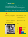
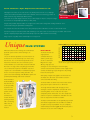
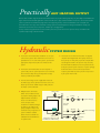
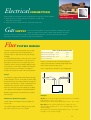
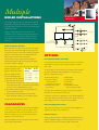
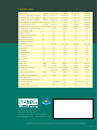
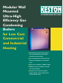
Modular Wall
Mounted
Ultra-High
Efficiency Gas
Condensing
Boilers
for Low Cost
Commercial
and Industrial
Heating
CONDENSING BOILERS
●
Small diameter plastic flue systems
can be extended up to 39 metres
vertically or horizontally
●
Low cost plastic flue material saving
thousands of pounds on installation
costs
●
Boilers from 38 kW to 100 kW output
●
Modular systems available to match
any heating output
●
Compact size and preassembled
design reduces space requirements
and installation time.
Keston
BOILERS
The commercial range of Keston wall mounted gas condensing boilers covers outputs from 38 kW
(Keston 130) to 100 kW (Keston 340) with single boiler units. As with all Keston Boilers each has
an extremely high efficiency performance of 98% (GCV).
Despite their powerful outputs each unit is designed for wall mounting though floor standing
installations can be accommodated for the Keston 260 and Keston 340 using an optional floor
standing frame.
Keston Boilers offer complete and cost effective solutions to commercial and industrial heating and
in all installations can offer the highest quality systems. These are very often at much lower costs
than a single commercial boiler of equivalent output.
Power
POINTS
●
Practically any heating output possible with modular system
●
Wall mounted with optional floor standing frame
●
Compact size from 889H x 500W x 327D
●
Up to 99.1% efficient – can save 30% or more on fuel bills
●
with virtually no NOx emissions (Class 5 rated)
●
Integral shunt pumps on Keston 260 and 340 models
●
Flue system is small diameter plastic pipe with lengths up to
●
Perfect match for Keston Spa hot water storage system -
●
●
Simple and quick to install and maintain - all access from
front and top.
●
Completely room sealed, can site practically anywhere,
no need for expensive dedicated boiler room with
combustion air ventilation.
39m (Keston 260 and 340) - vertical or horizontal - can
high efficiency commercial models up to 450 litre
save thousands of pounds in installation costs
storage.
Purpose designed boiler plant rigs available for easy
installation and drastically reduced site time.
●
No complicated PCB's
●
Exceptionally high quality stainless steel single pass heat
exchanger
●
LPG options available for Keston 130 and Keston 170
●
CE Marked, British Gas Approved and manufactured to
ISO 9001
COMBUSTION EMISSIONS NOx PPM
120
110
100
90
80
70
60
50
40
30
CONVENTIONAL
SYSTEMS
The patented
micro-mesh burner
produces a low flame
temperature and super
low NOx combustion
at levels well below
any published
requirement.
PROPOSED
GERMAN
‘BLUE-ANGEL’
LIMIT
20
10
KESTON
2
Keston Commercial - Higher Output Keston 260 and Keston 340
Following the immediate success of the Keston 130 (38 kW) and the Keston 170 (50 kW) light
commercial models Keston Boilers launched two additional commercial condensing gas boilers to
Sheltered Housing Project:
3 Keston 170’s
further extend its range of ultra high efficiency boilers
The Keston 260 (76 kW output) and Keston 340 (100 kW output) are unique in concept and design
and each have an exceptionally high efficiency at 98% (GCV).
Despite their powerful output the boilers are designed to be wall mounted, though floor standing installations can be
accommodated using the optional floor standing frame.
The compact size means these boilers can be sited practically anywhere without the need for a dedicated boiler room.
Each model comprises two boiler modules with individual gas valve, fans, burners and heat exchanger assemblies. Each module
operates completely independently and is automatically sequenced to offer maximum load matching.
Firing sequence is regularly rotated automatically to even usage levels.
FLUE SYSTEM
All Keston boilers have the advantage of a small diameter
plastic flue system and the commercial range is no
exception.
How It Works
The Keston modules use
a high powered
Full Load Efficiency vs. Return Water Temperature
BOILER EFFICIENCIES IN %
Unique
100
95
CONDENSI
90
85
80
STANDARD
75
The 50 mm diameter plastic flue used on the Keston 130
combustion blower to
and Keston 170 can be extended up to 29 metres away
deliver a premix of gas
from the unit. The 100 mm diameter plastic flue on the
and air to a downward
Keston 260 and Keston 340 can be extended up to 39
firing burner in a high
metres. All boilers can accommodate vertical or horizontal
efficiency single pass heat
flue routes. The usage of low cost plastic pipe for the flue
exchanger. The heat exchanger is made from highly
can save thousands of pounds on installation costs when
corrosion resistant stainless steel formed into a tightly wound
compared to a conventional flue. In refurbishment projects
coil. Hot combustion gases pass through the coil providing
there is no need for expensive relining of the flue. This
heat to the water system.
system is also ideal for buildings with difficult flue options and
particularly listed buildings with various restrictions.
Added benefits of
the flue flexibility is
that the boiler can
be sited practically
NG
70 20
30
40
60
50
WATER RETURNING TO BOILER °C
High efficiency condensing boilers produce more heat, using
the same amount of gas, than any other type of gas boiler.
Shunt pumps, integral to the appliance on the Keston 260
and Keston 340, will ensure each module receives the
correct water flow when firing.
The Keston boilers are of low mass and low water content
giving a rapid response when there is a call for heat.
anywhere in the
The design of Keston boilers, with its single pass heat
most convenient
exchanger, avoids the complications associated with other
position and the
condensing boilers and as a result does not require
flue can be
complicated printed circuit boards. The unit is totally room
terminated in a
sealed and requires no ventilation for combustion air to the
location where the
room or compartment in which it is installed.
"plume" generated
The Keston commercial boilers are exceptionally easy to install
with a condensing
and maintain and pipework header assemblies are available as
boiler does not
an option to assist speedy installation. They are completely
cause a visual
environmentally sound with negligible NOx emissions (Class 5
nuisance.
rated) and can save 30% on the heating bill.
3
70
Practically
ANY HEATING OUTPUT
Because of its modular design the Keston lends itself to almost any required heating output by way of multiple unit installations for
larger commercial or industrial applications and the benefits over a single commercial boiler are immense. The Keston modular
system is perfect for decentralisation programmes now happening in many commercial installations such as hospitals and
universities where one large commercial boiler is being replaced. From initial purchase through to installation, running and
maintenance, the Keston saves money, time, valuable space and aggravation.
In many commercial applications the Keston modular system has proved to be far less expensive to buy or install than the
equivalent output single commercial boiler.
Hydraulic
●
SYSTEM DESIGN
●
The Keston commercial boilers suitable for use on open,
The Keston 260 and Keston 340 boilers are supplied
vented water systems with combined feed and vent. It is
complete with integral boiler shunt pumps. However,
preferable for use on sealed water systems, provided the
these pumps are sized purely to provide adequate flow
appropriate components required are included in the
rate through the boiler at the pressure drop caused by
system.
the boiler itself. No allowance has been provided in the
shunt pump size for system resistance. A system pump(s)
●
The Keston commercial boilers do not incorporate a
should therefore be selected sized to provide the
system safety valve or system expansion vessel. Correctly
required system flow rate at the pressure drop created
sized and rated safety valve(s) and expansion vessel(s)
by the system index circuit.
must be provided by the installer.
●
The hot water storage vessel, if applicable, must be of
the indirect type, direct cylinders must not be used. The
Keston Spa unvented calorifier range is ideally suited to
the Keston commercial boiler.
●
Multiple Keston commercial
Safety Valve
boilers can be installed to meet
IV
any required heating output. The
IV
implementation of a balance
header is recommended to
ensure adequate water
AV
Pump
IV
System flow(s)
Boiler
Low loss
header
circulation is maintained through
the boiler by the boiler shunt
pumps (integral on Keston 260
IV
Strainer
IV
System return(s)
and Keston 340), irrespective of
system conditions. Suitable
balance header assemblies are
available from Keston Boilers as
an optional extra.
4
IV
IV
Shunt Pump
(integral on Keston 260
and Keston 340 models)
Fill Point
DOC
Expansion
Vessel
Electrical
CONNECTION
School Project:
3 Keston 170’s on a rig
Electrical supply and control of the Keston condensing boiler is dependent on model as follows:
●
Keston 130 and 170 10A permanent live, 2A switched live on/off control.
Shunt pump overrun control.
●
Keston 260 and 340 13A permanent live, volt free link on/off control.
Gas
SUPPLY
The Keston Condensing Boiler uses premix combustion technology which requires
adequate gas supply pressure and flow at all times during operation. Care should
therefore be taken to ensure that the supply, meter and distribution pipework is correctly sized for the gas flows required.
Details of gas consumption are provided on the back page of this brochure.
Flue
SYSTEM DESIGN
The Keston commercial condensing boiler range use high
Keston 130 & 170 Keston 260 & 340
powered combustion blowers that enable flueing over
Maximum Air Inlet Length
15.0m
20.0m
exceptional distances using small diameter plastic flue pipe
Maximum Flue Outlet Length 29.0m
39.0m
Maximum Combined Air Inlet 30.0m
and Flue Outlet Length
40.0m
and fittings.
The exceptionally high efficiency of the units ensure very low
flue temperatures which permits the use of such low cost
plastic pipe for the flue duct. A second plastic pipe carries
combustion air from outside the building enabling the boiler
to be installed in a room without ventilation for combustion
air purposes. Boiler room combustion air ventilation is
However, each bend used has an equivalent length that
must be deducted from the maximum straight length stated
above. Knuckle bends must not be used.
A 92.5° sweep elbow is equivalent to 1.0m straight length.
therefore not required for a Keston commercial installation.
Design
Air
Flue
For combustion air supply and flue exhaust individual air supply
and flue outlet pipes are used. The material used for flue outlet
&/or air inlet must be 50mm muPVC (BS5255) waste pipe for
the Keston 130 and Keston 170. Keston Composite pipe of an
internal diameter not less than 100mm is required for the
Boiler
Keston 260 and Keston 340 models. Suitable pipe and fittings
can be obtained via Keston Boilers Ltd appointed distributors.
Both flue outlet terminal and air inlet terminal are supplied
with each boiler.
Example
Minimum & Maximum Lengths
The flue outlet and air inlet pipes must have lengths of at
Air inlet uses one 92.5 sweep elbow. Hence, for a Keston 130 or 170 maximum
length permissible = 15.0m - 1.0m = 14.0m.
For a Keston 260 or 340 maximum length permissible = 20.0m - 1.0m = 19.0m.
least 1m each.
The maximum lengths of both air inlet pipe and flue outlet
pipe, when no bends are used, are as detailed.
Flue outlet uses one 92.5 sweep elbow. Hence, for a Keston 130 or 170
maximum length permissible = 30.0m - 1.0 m - total air inlet length = 29.0m total air inlet length.
For a Keston 260 or 340 maximum length permissible = 40.0m - 1.0m - total air
inlet length = 39.0m - total air inlet length.
5
Slope
The two terminals are subject to the requirements of BS
5440 Pt 1 for clearances from features of the building
'Horizontal' flue outlet pipework MUST slope at least 2.5
although some can be decreased to the values indicated.
degrees (45 mm per metre run) downwards towards the
boiler. Pipework can be vertical. Only swept elbows can be
If either the air inlet or the flue outlet terminate at a height
used. For installations requiring reduced slope contact
of less than 2m (6ft) above ground level the termination
Keston Boilers Technical Support.
must be protected by a suitable guard. Suitable terminal
guards can be obtained from Tower Flue Components Ltd
Air inlet pipework can be truly horizontal or vertical, or
or its distributors.
sloping in a downward direction towards the boiler but in
The Keston Condensing Boiler, as with any condensing
pipe. There must be no troughs in any of the pipework,
boiler, will generate a condensate "plume" from the flue
whether it be air inlet or flue outlet.
terminal in all weather conditions. Consideration must
To Terminal
this case rain, etc, must be prevented from entering the
Due to the low temperature of the flue
gases further condensate will form within
the flue system. Drain points, with
therefore be given to the effect of this "plume" when
selecting a location for the flue terminal.
It is advisable for horizontal flue terminals to place a 45°
To Boiler
suitable traps, must therefore be
Tee
Fitting
incorporated within the flue
system at the base of vertical flue sections
6 in
min
in excess of 4m (2m for the Keston 130
and Keston 170). These additional
elbow at the end of the flue to direct the condensate plume
up and away from the property.
Flue outlet and air inlet terminations must be at least 60 mm
and 95 mm respectively from the wall face.
condensate drains must be run to discharge as detailed in
There is no maximum distance between flue terminal and
section "Condensate Drainage". Such drain points can be
air inlet terminal - the terminations can be on opposite sides
formed using standard Keston Composite flue fittings.
of the dwelling if desired.
A minimum clearance of at least 500 mm must be left
Terminations
between the terminations.
Air inlet terminals must be positioned to ensure only fresh
air is drawn into the boiler. The air terminal must be located
Compartment Installation
outside of the building.
The casing temperatures of the Keston commercial boilers
Drawing of combustion air directly from a ventilated boiler
are very low. Due to this fact, no compartment ventilation is
room will invalidate the heat exchanger warranty.
required for cooling purposes.
The flue outlet terminal is designed to face outwards but
can, if desired, be adapted to face in any direction BUT must
Condensate Drainage
not be directed in the region of the air inlet. Where the air
Being a condensing boiler, the Keston is fitted with a
and flue terminals are located in close proximity the flue
condensate trap at the base of the heat exchanger and flue
terminal should be located above the level of the air inlet
assembly, with facility to connect to a drain point underneath
terminal.
the appliance.
Use only plastic piping and do not reduce below 22mm
Minimum Flue Terminations and
Air Inlet Dimensions (mm)
Flue
Air
Terminal Inlet
A Below or beside openable window, air brick etc. 500
50
B Below gutters, soil pipes, drain pipes
75
75
C Below eaves
300
50
D Below balconies or car port roof
200
50
E From vertical drain or soil pipes
75
50
F From internal or external corner
600
50
G Above ground or balcony or roof
300
100
H From surface facing a terminal
600
100
I From terminal facing a terminal
1200
1200
J From opening in a car port
1200
100
K Vertically from terminal on same wall
1500
1500
L Horizontally from terminal on same wall
300
300
6
internal diameter within the dwelling. Condensate should
preferably be drained into the sanitary waste system or,
alternatively, the rainwater system of the property.
Termination of the pipe must be either at a branch or stack
internal to the building, or externally at an open gully.
Alternatively, discharge into a purpose made condensate
soakaway can be considered. Existing or purpose built drains
must use suitable corrosion resistant material as condensate
is mildly acidic.
A minimum slope downwards towards the drain of 1 in 20
is essential. Freezing of the termination and pipework must
be prevented. Any drainage pipes outside the property must
be at least 32 mm inside diameter.
Multiple
BOILER INSTALLATIONS
Hospital Project:
6 Keston 170’s
The modular design of the Keston Commercial range lends
Safety Valve
itself ideally to multiple boiler installations. As a result almost
AV
IV
any heating output requirement can be accommodated using
IV
multiple Keston units.
IV
Using this multiple boiler approach the system can be
Boiler
controlled to ensure optimum matching of boiler output to
IV
Boiler
Pump
Pump
taken off-line for servicing with minimal impact on system
performance.
Shunt Pumps
(integral on Keston 260
and Keston 340 models)
Common Balance Headers
IV
Strainer
IV
IV
Strainer
IV
Fill Point
DOC
If flow cannot be maintained through the system pipework
to meet the minimums required by the boiler the boiler will
"kettle" or even produce steam. The implementation of a
balance header, as shown in the schematics, is
OPTIONS
recommended to ensure adequate water circulation is
Preassembled Boiler Plant Rigs
maintained through the boiler by the boiler shunt pumps,
In circumstances where site time and/or space may be at a premium
irrespective of system conditions.
Keston Boilers can provide a pre-assembled solution to any plant
The size of the balance header is dependant on the number
room needs.
of boilers serving the header
The Keston Rigs are delivered to site pre-assembled and incorporate
header the following design
considerations must be observed:
a) Each boiler must have its own
System return(s)
IV
IV
Boiler water flows are critical to the operation of the boilers.
When assembling a balance
System flow(s)
IV
Low loss
header
load at any given time. In addition, individual units can be
A guide to sizing is given here:
IV
Total Boiler
Output
Header
Diameter
up to 100kW
3"
up to 200kW
4"
up to 300kW
4.5"
up to 400kW
5"
up to three units within a floor standing frame. The units are prepiped to a single balance header.
The Keston Rigs include :
●
Safety Valves
●
Up to three Keston
●
Isolating Valves
commercial units as
●
Test Points
specified by the customer
●
Drain Points
Individual shunt pumps
●
Single Balance Header
flow and return connection to the balance header pipe.
Common flow and return connections with other boilers
can cause reverse circulation effects to occur.
●
for each unit
sized according to output
b) The minimum distance between the system flow and
return connections is 600mm
c) A drain off point should be fitted to the base of the
header, along with cleaning access, for sludge removal.
The top of the header should be vented.
The incorporated equipment is pre-piped and pre-wired ready for
immediate connection within the plant room.
The balance header includes tappings for air vent, fill point/expansion
vessel, drain off and system flow and return. The number and size of
system tappings is as per the customers own specification.
CLEARANCES
Floor Standing Boiler Frame
The boilers are designed for ease of servicing and installation.
Where plant room wall space is at a premium a floor standing frame is
On the Keston 260 and Keston 340 all servicing is carried
available for the Keston 260 and Keston 340.
out through the front of the unit. On the Keston 130 and
Keston 170 additional access is required to the top of the
cabinet for removal of the burner.
Balance Headers
A range of standard headers is available from Keston Boilers Ltd for
Details of installation clearances are provided in the table on
single and multiple installations. In addition bespoke headers can be
the back page of this brochure.
produced in order to meet customers specific requirements.
7
Expansion
Vessel
Performance Data
Keston 130
Keston 170
Keston 260
Keston 340
Max Input (GCV)
kW/(Btu/h)
42.3/(144,330)
55.0/(187,660)
84.6/(288,650)
110.0/(375,300)
Max Output to water (80/60 Flow/Return)
kW(Btu/h)
38.1/(130,000)
49.8/(170,000)
76.1/(259,650)
99.0/(337,800)
Max Output to water (60/40 Flow/Return)
kW(Btu/h)
40.0/(136,500)
52.4/(178,800)
79.5/(271,250)
104.0/(354,800)
Max Output to water (50/30 Flow/Return)
kW/(Btu/h)
41.4/(141,500)
54.5/(186,000)
82.9/(282,850)
107.8/(367,800)
7.5/(3)
10.0/(4)
9.8/(3.9)
13.0/(5.2)
Gas Consumption after 10 mins
3
l/s / (ft /hr)
1.09/(139)
1.42/(181)
2.19/(278)
2.84/(362)
Required Inlet Gas Pressure (Dynamic)
mbar/(in wg)
20.0/(8.0)
20.0/(8.0)
20.0/(8.0)
20.0/(8.0)
Recommended Temperature Differential
°C
10 to 15
10 to 15
10 to 15
10 to 15
Required Water Flow Rate
l/s
0.83
1.00
1.60
2.00
No
No
Yes
Yes
Burner Setting Pressure - Hot (factory preset) mbar/(in wg)
Integral Shunt Pumps
Max Operating Flow Temperature
°C
80.0
80.0
80.0
80.0
Max Head (Open Systems)
m
30.5
30.5
30.5
30.5
Max Press. (Sealed Systems)
Bar
2.70
2.70
2.70
2.70
Min Head (Open Systems)
m
3.0
3.0
3.0
3.0
Electrical Supply
230V 50Hz
230V 50Hz
230V 50Hz
230V 50Hz
Power Consumption (Max)
W
600
600
1200
1200
Cabinet Height
mm
890
890
1260
1260
Cabinet Width
mm
500
500
1080
1080
Cabinet Depth (Max)
mm
327
327
350
350
Top Clearance
mm
254
254
127
127
Side Clearance
mm
1
1
1
1
Base Clearance
mm
127
127
127
127
Front Clearance
mm
305
305
305
305
Weight – Full
kg/(lbs)
68/(150)
68/(150)
165/(363)
165/(363)
Weight – Empty
kg/(lbs)
61/(134)
61/(134)
150/(330)
150/(330)
Flow and Return Connections
35mm copper
35mm copper
Rp 2"F
Rp 2"F
Gas Connection
3
/4 BSPT Male
Rp 1.25"F
Rp 1.25"F
/4 BSPT Male
3
Flue Pipe Size (Nominal Bore)
mm/(in)
50/(2)
50/(2)
100/(4)
100/(4)
Air Intake Pipe Size (Nominal Bore)
mm/(in)
50/(2)
50/(2)
100/(4)
100/(4)
Max Air Intake Length
m
15
15
20
20
Max Combined Flue & Air Intake Length
m
30
30
40
40
Flue and Air Intake Material
muPVC BS5255 Pipe Only
LPG Option available
Optimum Flue Gas CO2 Level (G20)
%
Keston Composite Pipe Only
Yes
Yes
No
No
8.4
8.4
8.4
8.4
Agent
34 West Common Road, Hayes
Bromley, Kent, BR2 7BX, UK
Telephone: 020 8462 0262
Fax: 020 8462 4459
Email: [email protected]
Web: www.keston.co.uk
In accordance with our policy of constant improvement we reserve the right to alter the design and specification without prior notice.
All illustrations included in this brochure are for general guidance only. As such these illustrations are not intended as final design drawings.
10/99