1
iNSTALLATiON AND SERVICE MUST BE PERFORMED BY A QUALiFiED iNSTALLER.
iMPORTANT: SAVE FOR LOCAL ELECTRICAL iNSPECTOR'S USE.
READ AND SAVE THESE iNSTRUCTiONS FOR FUTURE REFERENCE.
If the information
causing
property
damage,
in this manual
personal
is not followed
exactly, a fire or explosion
may result
injury or death.
FOR YOUR SAFETY:
B
Do not store or use gasoline or other flammable
vicinity of this or any other appliance.
WHAT TO DO IF YOU SMELL GAS:
vapors
and liquids in the
®
Do not try to light any appliance.
®
Do not touch any electrical switch; do not use any phone in your building.
Immediately
call your gas supplier from a neighbor's
phone.
Follow the gas supplier's
instructions.
if you cannot reach your gas supplier, call the fire department.
Installation
and service must be performed by a qualified
installer, service
supplier.
®
®
agency
or the gas
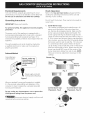
i
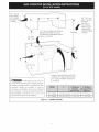
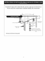
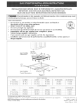
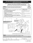
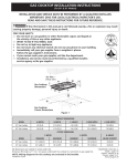
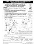
30" Min.
Gas Cooktop
Dimensions
(76.2 cm) _
. _
A/:J-
B
----_
c
21/2
- -::::::_::( _-....
Gas Cooktop
Cutout Dimensions
H ...... _ _--c::- ....
(6.4 cm)
'
_c ;_
ii
Figure I
30" GasCooktop
30 (76.2)
21s/4(55.2)
41/4(10.8)
27 (68.6)
19 (48.3)
36" GasCooktop
36 (91.4)
21s/4(55.2)
41/4(10.8)
331/4(84.5)
19 (48.3)
30" GasCooktop
271/4(69.2)
281/2(72.4)
191/8(48.6)
198/4
(50.2)
8 (20.3)
36" GasCooktop
337/8(86.1)
341/4(87)
191/8(48.6)
19Y4(50.2)
8 (20.3)
All dimensions are stated in inches and (cm).
Dimension H includes a 5" (12.7 cm) space underneath the cooktop for connection to gas supply line.
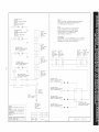
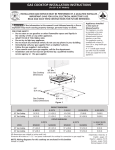
NOTE: Wiring diagrams for this cooktop are enclosed in this booklet
Printed in Canada
318201495 (1105) Rev.A
English - pages 1-9
Espaflol - p_iginas 10-18
Wiring Diagram 19-20
important
Notes to the Installer
1. Read all instructions contained in these installation
2.
3.
4.
5.
instructions before installing the cooktop.
Remove all packing material before connecting the
electrical supply to the cooktop.
Observe all governing codes and ordinances.
Be sure to leave these instructions with the consumer.
Note: For operation at 2000 ft. elevations above see
level, appliance rating shall be reduced by 4 percent
for each additional 1000 ft.
important
Note to the Consumer
Keep these instructions with your Use and Care Guide for
future reference.
IMPORTANT SAFETY
INSTRUCTION
Installation of this cooktop must conform with local
codes or, in the absence of local codes, with the National
Fuel Gas Code ANSI Z223.1/NFPA 54 in the United
States, or in Canada, with the Canadian Fuel Gas Code,
CAN/CGA B149 and CAN/CGA B149.2.
• When installed in a manufactured (mobile) home
installation must conform with the Manufactured
Home Construction and Safety Standard, title 24 CFR,
part 3280 [Formerly the Federal Standard for Mobile
Home Construction and Safety, title 24, HUD (part
280)] or, when such standard is not applicable, the
Standard for Manufactured Home Installation, ANSI/
NCSBCS A225.1 or with local codes where applicable.
This cooktop has been design certified by CSA
International. As with any appliance using gas and
generating heat, there are certain safety precautions you
should follow. You will find them in the Use and Care
Guide., read it carefully.
Be sure your cooktop is installed and grounded
properly by a qualified installer or service
technician.
This cooktop must be electrically grounded in
accordance with local codes or, in their absence,
with the National Electrical Code ANSI/NFPA
No. 70--latest edition in the United States, or in
Canada, with the Canadian Electrical Code, CSA
C22.1 Part 1.
The burners can be lit manually during an
electrical power outage. To light a burner, hold a
lit match to the burner head, then slowly turn the
Surface Control knob to LITE. Use caution when
lighting burners manually.
Do not store items of interest to children in
cabinets above the cooktop. Children could be
seriously burned climbing on the cooktop to reach
items.
To eliminate the need to reach over the surface
burners, cabinet storage space above the burners
should be avoided.
Adjust surface burner flame size so it does not
extend beyond the edge of the cooking utensil.
Excessiveflame is hazardous.
Never use your cooktop for warming or heating
the room. Prolonged use of the cooktop without
adequate ventilation can be hazardous.
Do not store or use gasoline or other flammable
vapors and liquids near this or any other
appliance. Explosions or fires could result.
The electrical power to the cooktop
must be shut off while gas line connections are
being made. Failure to do so could result in serious
injury or death.
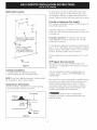
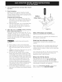
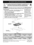
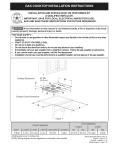
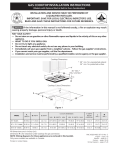
13" (33cm)
Max.Depth
ForCabinet
Installed
Above
Cooktop.
30" (76.2cm)
_¢
18" Min.
(45.7cm)
11/2"(3.8cm)MinimumDistance
Between
RearEdgeof Cutout
andNearest
Combustible
Surface
AboveCountertop.
Clearance
Between
the Top of
the Cooking
Platform
and
in. Clearance
Unprotected
Wood or Metal
Cabinet
B
I
24" (6! cm)
To eliminate the risk of burns
or fire from reaching over heated surfaces,
cabinet storage space located above the
cooktop should be avoided.
If cabinet
storage is provided, risk can be reduced
by installing a range hood that projects
horizontally
a minimum of 5" (1 2.7 cm)
beyond the bottom of the cabinets.
Drawers Cannot Be Used with This
Cooktop Since Burner Box Extends
3%2" (8.02 cm) Below Surface of
Countertop.
30" C00kt0p
30" (76.2 cm)
5" (12.7cm)
5" (12.7 cm)
36" C00kt0p
36" (91.4 cm)
5" (12.7cm)
5" (12.7 cm)
Figure 2 - CABINET DESIGN
3
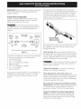
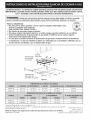
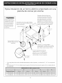
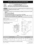
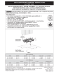
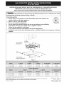
Typical Gas Cooktop Installation Over
an Electric Built-in Oven Installed Under the Counter
I
18" (45.7 cm) Max.-----_
II
I
÷
4" (10.2 cm)
Manifold Pi
61/2"
5"
.(16.5 cm)
Flare (12.7 cm) Min.
Union
Flexible Connector
Flare
Union
120V/6OHz
Grounded
Outlet
Right Side
of Cabinet
Pressure
Cabinet sides or
filler panel
Wall Oven Cabinet
Regulator
Manual Shutoff Valve
(To be accessible
for shut-off valve
operation)
Typical Under Counter Installation of an Electric Built-in
Oven with a Cooktop Mounted Above
Junction box must
All mounting
hardware must
be used to secure
the built-in oven
to the cabinets.
Refer to the built-in
oven installation
instructions.
This cooktop may be
installed over certain
built-in electric oven
models.
be located approx.
3" to the left of
the built-in oven
cutout.
Side filler panels are necessary to
isolate the unit from adjoining
cabinets. Panel height should allow
for installation of approved cooktop
models. See "Typical Gas Cooktop
Installation Over an Electric Built-in
Oven Installed Under the Counter"
on previous page.
32" Min.**
(81.3 cm)
36"
(91.4 cm)
208/240 Volt grounded junction
box for built-in oven.
Use 3/4" (1.9 cm) plywood, installed on
two runners, flush with toe plate. Must
be capable of supporting 150 Ibs.
Cut an opening in wood base minimum
9" (22.9 cm) x 9" (22.9 cm), 2" (5.1 cm)
from left side filler panel, to route armored
cable to junction box.
4 1/2" (1 1.4 cm)
Max.*
*
**
If no cooktop is installed directly over the oven unit, 5" (12.7 cm) maximum is allowed.
32" (81.3 cm) min. from top of cabinet to top of runners must be maintained.
30" (76.2cm)
271/4"(69.2 cm)
28 s/8" (72.7 cm)
281/2"(72.4 cm)
29" (73.7 cm)
231/2"(59.7 cm)
27" (68.6cm)
271/4
'' (69.2 cm)
28 s/8" (72.7 cm)
24 7/8" (63.1 cm)
251/4
'' (64.1 cm)
231/2
'' (59.7 cm)
Wall Outlet
Location
,
To clamp down, insert an angle bracket into the slot
on each side of the unit as shown.Run thumb screw
up through the bracket, up against the bottom of the
counter. Tighten until the unit draws down and is secure.
12,, --_
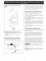
Provide
an Adequate
Gas Supply
This cooktop is designed to operate on natural gas at 4"
of manifold pressure only.
I
10 "
A pressure regulator is connected in series with the
manifold on the cooktop and must remain in series with
the supply line.
I
, Recommended
area for
' 12OV grounded outlet
u
on rear wall.
m
CL_olFUL_E
T
For proper operation,
the maximum inlet pressure
to the regulator must be no more than 14" of water
column (W.C.) pressure.
22 "
: NOTE: If an outlet
J is not available,
: have one installed by
t a qualified technician.
I
I
For checking the regulator, the inlet pressure must be at
least 1 " (or 2.5 kPa) greater than the regulator manifold
pressure setting. The regulator is set for 4" of manifold
pressure, the inlet pressure must be at least 5".
The gas supply line to the range should be 1/2" or 3/4"
pipe.
OF UNIT
LP/Propane
Gas Conversion
This appliance can be used with Natural gas or LP/
Propane gas. It is shipped from the factory for use with
natural gas.
Figure 3
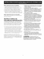
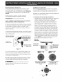
Cooktop
Installation
1. Visually inspect the cooktop for damage.
2. Set the cooktop into the countertop cutout.
NOTE: Do not use caulking compound; cooktop should
be removable for service when needed.
Clamp
Down
Information
Once the cooktop is installed in the counter opening,
you must clamp the unit down as shown.
Counte_op
Cooktop
_
/
)_"Thumb
Screw
Figure 4
A kit for converting to LP gas is supplied with your
cooktop. The kit is marked "FOR LP/PROPANEGAS
CONVERSION".
The conversion must be performed by a qualified service
technician in accordance with the kit instructions and
all local codes and requirements. Failure to follow
instructions could result in serious injury or property
damage. The qualified agency performing this work
assumes responsibility for the conversion.
Failure to make the appropriate
conversion can result in serious personal injury and
property damage.
Important: Remove
allpackingmaterialandliterature
fromcooktopbeforeconnecting
gasandelectrical
supplyto cooktop.
The supply line must be equipped with an approved
manual shutoff valve. This valve should be located in the
same room as the cooktop and should be in a location
that allows ease of opening and closing. Do not block
access to the shutoff valve. The valve is for turning on or
shutting off gas to the appliance.
Install Pressure Regulator
Installthe pressure
regulatorwith thearrowonthe
regulatorpointinguptowardtheunitin a position
whereyoucanreachtheaccess
cap.
Donot maketheconnection
too tight.
Theregulatorisdiecast.Overtightening
maycrackthe
regulatorresultingin a gasleakandpossible
fire or
explosion.
Manual
Shutoff
Valve
Flare
Union
GAS FLOW
_
Flare
Union
Pressure
Regulator
Shutoff
Open
Valve
-
position
Figure 6
Nipple
Off
Flexible
Connector
Nippl
Access
Cap
Once regulator is in place, open the shutoff valve in the
gas supply line. Wait a few minutes for gas to move
through the gas line.
All connections must be wrench-tightened
Figure 5
Check for leaks. After connecting the cooktop to the
gas supply, check the system for leaks with a manometer.
If a manometer is not available, turn on the gas supply
and use a liquid leak detector (or soap and water) at all
joints and connections to check for leaks.
Assemble the flexible connector from the gas supply pipe
to the pressure regulator in the following order:
1. manual shutoff valve
2. 1/2" (1.3 cm) nipple
3. 1/2" (1.3 cm) flare union adapter
4. flexible connector
5. 1/2" (1.3 cm) flare union adapter
6. 1/2" (1.3 cm) nipple
7. pressure regulator
Do not use a flame to check for leaks from
gas connections. Checking for leaks with a flame may
result in a fire or explosion.
Tighten all connections if necessary to prevent gas
leakage in the cooktop or supply line.
Use pipe-joint compound made for use with Natural and
LP/Propane gas to seal all gas connections. If flexible
connectors are used, be certain connectors are not
kinked.
Check alignment of control knob valves after
connecting the cooktop to the gas supply to be sure the
cooktop manifold pipe has not moved. A misalignment
could cause the valve stems to rub on the control panel,
resulting in a gas leak at the valve.
Disconnect this cooktop and its individual manual
shutoff valve from the gas supply piping system during
any pressure testing of that system at test pressures
greater than 1/2 psig (3.5 kPa or 14"water column).
Isolate the cooktop from the gas supply piping
system by closing its individual manual shutoff valve
during any pressure testing of the gas supply piping
system at test pressures equal to or less than 1/2 psig
(3.5 kPa or 14" water column).
7
Electrical
Requirements
120 volt, 60 Hertz, properly grounded branch circuit
protected by a 15 amp circuit breaker or time delay fuse.
Do not use an extension cord with this cooktop.
Check
Refer to
cooktop
cleaning
Grounding
Do not touch the burners. They may be hot enough to
cause burns.
Instructions
Operation
the Use and Care Guide packaged with the
for operating instructions and for care and
of your cooktop.
IMPORTANT Please read carefully.
.
For personal
grounded.
safety, this appliance
must be properly
The power cord of this appliance is equipped with a
3-prong (grounding) plug which mates with a standard
3-prong grounding wall receptacle (see Figure 7) to
minimize the possibility of electric shock hazard from the
appliance.
The wall receptacle and circuit should be checked by
a qualified electrician to make sure the receptacle is
properly grounded.
Preferred
Method
Grounding type
wall receptacle
not, under any
circumstances, cut,
remove, or bypass
the grounding
prong.
Install Burner Caps
This cooktop is equipped with sealed burners. All
pieces are at their place. Take note where they
are. Remove all packaging material. Make sure the
burner caps are properly aligned and leveled. The
burner cap lip (See Fig. 8) should fit snug into the
center of burner head and rest level. Refer to Figs. 9
& 10 for correct and incorrect burner cap placement.
Once in place, you may check the fit by gently sliding
the burner cap from side to side (Fig. 11) to be sure
it is centered and firmly seated. When the burner
cap lip makes contact inside the center of the burner
head you will be able to feel it. Please note that the
burner cap should NOT move off the center of the
burner head when sliding from side to side. NOTE:
There are no burner adjustments necessary on this
cooktop.
=°=°,
Head
\=°=o,
Cap Lip
Fig. 8
Power supply cord with
3-prong grounding plug.
Figure 7
Where a standard 2-prong wall receptacle is installed,
it is the personal responsibility and obligation of the
consumer to have it replaced by a properly grounded
3-prong wall receptacle.
Correct Burner Cap
Placement
- Fig. 9
Do not, under any circumstances, cut or remove the
third (ground) prong from the power cord.
Disconnect electrical supply cord from wall
receptacle before servicing cooktop.
Fig. 11
Incorrect
Burner Cap
Placement
- Fig. 10
2. Turnon ElectricalPowerandOpenMain Shutoff
Gas Valve
3_
Check the igniters
Operation of electric igniters should be checked
after cooktop and supply line connectors have been
carefully checked for leaks and the cooktop has been
connected to electric power.
To operate the surface burner:
A. Push in and turn a surface burner knob to the
B.
Hollow
Valve Stem.
LITE position. You will hear a small ticking noise;
this is the sound of the electric ignitor which
lights the burner.
After the burner lights, turn to the desired flame
size. The controls do not have to be set at a
particular mark. Use the marks as a guide and
adjust the flame as needed.
4_
Figure 12
Adjust the "LO" or "SIMMER" Setting of Surface
Burner Valves (see Figure 12)
Push in and turn each control knob to the "LO" (or
"SIMMER") setting. The "LO" setting of each burner
has been set at the factory to the lowest setting
available to provide reliable reignition of the burner.
If it does not stay lit on the "LO" setting, check the
setting as follows.
When All Hookups
are Complete
Make sure all controls are left in the OFF position.
Make sure the flow of combustion and ventilation air to
the cooktop is unobstructed.
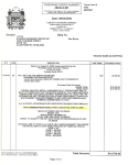
Model
Be careful when performing this
Allow cooktop to cool to room temperature.
Light all burners by turning each control knob to
LITE until burners ignite, and then set them at
"HI".
C.
_
turn the knob of the burner you want to
adjust to the LOWEST POSITION.
If burner goes out, readjust valve as follows:
Remove the surface burner control knob, insert
a thin-bladed screw driver into the hollow valve
D.
Number
Location
When ordering parts for or making inquires about your
range, always be sure to include the model and serial
numbers and a lot number or letter from the serial plate
of your cooktop.
Your serial plate also tells you the rating of the burners,
the type of fuel and the pressure the cooktop was
adjusted for when it left the factory.
stem and engage the slotted screw inside. Flame
size can be increased or decreased with the turn
of the screw. To increase flame size turn the
screw counterclockwise and to decrease turn
Before
You Call for Service
Read the Before You Call for Service Checklist and
operating instructions in your Use and Care Guide.
It may save you time and expense. The list includes
common occurrences that are not the result of defective
clockwise. Adjust flame until you can quickly
turn knob from HI to LOWEST POSITION without
E.
Serial
The serial plate is located on the underside of the
cooktop.
operation.
A.
B.
and
workmanship or materials in this appliance.
extinguishing the flame. Flame should be as
small as possible without going out.
If you need to adjust another burner, repeat the
steps from A to D above until all burners operate
properly.
Refer to your Use and Care Guide for Sears service
phone numbers, or call 1-800-4-MY-HOME ®.
9
LA INSTALACION Y EL SEP,VICIO DEBEN SEP, P,EALIZADOS POP, UN INSTALADOP, CALIFICADO.
IMPOP,TANTE: GUAP,DE ESTAS INSTP,UCCIONES PAP,A USO DEL INSPECTOP, ELI'CTP,ICO LOCAL.
LEA Y GUAP,DE ESTAS INSTP,UCCIONES PAP,A FUTUP,AS P,EFEP,ENCIAS
!_
ocurrir
Si todas las instrucciones de _ste manual no son observadas
a la letra, se puede
incendios o explosiones
que pueden causar daEos materiales,
lesiones o la muerte.
PARA SU SEGURIDAD:
-- No almacene o utilice gasolina u otros vapores y liquidos inflamables cerca
de _ste o cualquier otto artefacto.
-- QUE HACER SI HAY FUGAS DE GAS :
• No intente de encender ningun artefacto
• No toque ningun interruptor
el_ctrico; no utilice ningun aparato telef6nico
en su edificio.
Llame inmediatamente
el abastecedor
de gas desde el tel_fono
de un vecino. Siga las
instrucciones del abastecedor
de gas.
En caso que no puede contactar
el abastecedor
de gas llame al departamento
de bomberos.
--La instalaci6n y el servicio
servicio t_cnico certificado
telef6nico
deben set realizados
o pot el abastecedor
de gas.
pot un instalador
calificado,
pot un
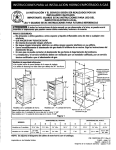
30" Mfn.
Dimensiones
de la parrilla
de cocinar
(76,2 cm)
]_
El
21/2"
(6.4
Dimensiones
del hueco de
la parrilla de cocinar
(6.4 cm)
, II
Figura I
M0del0 30"
30 (76.2)
213/4(55.2)
41/4(10.8)
27 (68.6)
19 (48.3)
M0del0 36"
36 (91.4)
213/4(55.2)
41/4(10.8)
331/4(84.5)
19 (48.3)
Modelo30"
271/4(69.2)
281/2(72.4)
191/8(48.6)
19s/4(50.2)
8 (20.3)
Modelo36"
337/8(86.1)
341/4(87)
191/8(48.6)
19s/4(50.2)
8 (20.3)
Todas las dimensiones se dan en pulgadas (cm).
La dimensi6n H incluye un espacio de 5" pot debajo de la plancha de cocinar para la conexi6n
de la linea de suministro de gas.
NOTA: Se adjunta los diagramas
Imprimiclo en Canada
318201495 (1105) Rev.A
English- pages 1-9
de cables de esta plancha de cocinar con el ]ibreta.
Espaflol- p_iginas10-18
Diagrama de la instalaci6nal_imbrica19-20
Notas
Asegurese que la plancha de cocinar sea instalada
y puesta a tierra correctamente
pot un instalador
o t_cnico califkado.
La plancha de cocinar debe conectarse
el_ctricamente
a tierra de acuerdo con los codigos
locales o, de no existir, con el codigo el_ctrico
ANSI/NFPA No. 70 = _ltima edicion en los Estados
Unidos, or in Canada, con el Canadian Electrical
Code, CSA C22.1 Parte 1.
Los quemadores pueden encenderse
manualmente
durante una interrupcion
del
suministro el_ctrico. Para encender un quemador,
mantenga un fosforo encendido en el extremo del
quemador, luego gire suavemente la perilla hasta
LITE (encendido). Tenga cuidado al encender los
quemadores en forma manual.
No deje articulos que interesan los nifios en los
armarios que est_n sobre la plancha de cocinar.
Les podria causar quemaduras graves si intentan
subirse para alcanzarlos.
Para eliminar el riesgo de extender pot encima
de los quemadores superiores, deberia evitar
el espacio de almacenamiento
del armario,
Iocalizado pot encima de estos quemadores
Gradue el tamafio de la llama de modo que
no sobrepase el borde del utensilio de cocina.
Demasiada llama es peligrosa.
• No utilice jamas la cocina como calefactor
El uso
prolongado de la cocina sin la ventilaciOn adecuada
puede set peligroso.
Mantenga el area cerca de este artefacto
o de cualquier otto artefacto despejada de
sustandas combustibles,
gasolina y otros liquidos
inflamables.
Se puede ocurrir incendios o explosiones.
importantes
para el instalador
1. Lea todas las instrucciones de instalaciOn antes de
realizar la instalaci6n de la plancha de cocinar.
2. Retire todos los articulos de embalaje antes de realizar
las conexiones el_ctricas a la plancha de cocinar.
3. Observe todos los c6digos o reglamentos estatales
4. Aseg0rese que el consumidor tenga estas instrucciones.
5. Nota: Para el correcto funcionamiento en lugares
superiores a los 2000 ft, el r_gimen del mecanismo debe
reducirse un 4% pot cada 1000 ft sobre el nivel del mar.
Notas importantes
para el consumidor
Guarde todas las instrucciones con su manual del usuario
para futuras referencias.
INSTRUCCIONES DE
SEGURIDAD IMPORTANTES
La instalaciOn de esta plancha de cocinar debe realizares
en conformidad con los c6digos locales o, si estos no
existen, con el National Fuel Gas Code ANSI Z223.1/NFPA
54 en los Estados Unidos, o en Canada, con el Canadian
Fuel Gas Code, CAN/CGA B149 y CAN/CGA B149.2.
• La instalaciOn de aparatos diseflados para instalaciOn
en casas prefabricadas (m6viles) debe conformar con el
Maufactured Home Consturction and Safet Standard,
titulo 24CFR, parte 3280 [Anteriormente el Federal
Standard for Mobil Home Construction and Safety,
titulo 24, HUD (parte 280)] o cuando tal est_indar no se
aplica, el Standard fo Manufactured Home Installation,
ANSI/NCSBCS 225.1, o con los c6digos locales.
El diseho de esta plancha de cocinar cuenta con la
aprobaci6n de la CSA internacional. AI igual que todos los
artefactos a gas que generan calor, deben seguirse ciertas
medidas de seguridad. Vienen con el Manual del Usuario.
Lea atentamente el manual.
I!_
El suministro
electrico
a la
plancha de cocinar debe de set cerrado durante
las conexiones a la linea. De Io contrario se puede
resultar lesiones graves o la muerte.
11
M_ix.profundidad
degabinetes
instalados
por
encimadela
plancha
de
empotares13"
(33cm).
4J
18" Min.
(45.7 cm)
11/2" (3.8 cm) Minimo Distancia
entre el horde posterior del
hueco y lamas cerca superficie
combustible por encima del
mostrador.
30" (76.2
cm) Minimo
de espacio
entre la parte
superior de
la plataforma
de la plancha
de cocinar y
el fondo de
una madera
non protegida
o armario
met_qlico.
Es)acio
C
No es posible utilizar cajones con
esta parrilla de cocinar porqu_ la
caja de empalme se extiende de
3%2" (8.02 cm) por encima de la
superficie del mostrador.
Para eliminar el riesgo de
alargar sobre los unidades en calentamiento
de la superficie, deberia evitarse el espacio de
almacenamiento del armario, ubicado sobre
las unidades de la superficie. Si se cuenta con
este espacio, se puede disminuir el peligro
instalando una cubierta de cocina que se
extienda horizontalmente en 5" (12.7 cm)
minimo por sobre la parte inferior delantera
en los armarios.
a
30"
36"
30" (76.2 cm)
5" (12.7cm)
5" (12.7 cm)
36" (91.4 cm)
5" (12.7cm)
5" (12.7 cm)
Figura 2 - DIeSENOS DEL ARMARIO
12
a:
Instalacion tipica de la plancha de cocinar a gas por encima de un
homo electrico empotrado
instalado debajo del mostrador
I
_
18" (45.7 cm) M_ix.-----_
II
I
÷
4" (10.2cm)
61/2"
Tubo mOIti
5"
(13.5 cm)
(12.7 cm) Min.
UniOn
Conector flexible
UniOn
UniOn
20V/6OHz Toma
de corriente a
tierra
Lado derecho
del armario
Regulador de
presi6n
Cabinet sides or
filler panel
V_ilvula de cierre manual
(Debe de set accesible para el
I funciona-miento de la wilvula de
cierre)
Armario
del horno
de pared
13
Tipica instalaci6n
de un horno el ctrico
empotrado
plancha de cocinar por encima
Todas las fijaciones de
montaje deben de estar
utilizadas para sujetar
el homo empotrado a
los armarios. Refiere
alas instrucciones de
instalaci6n del homo
empotrado.
Esta plancha de cocinar puede instalarse
por encima de algunos modelos de homo
electrico empotrado.
Aproximadamente
con una
Entrepa_os Ilenador de lados son
necesarios para aislar el aparato de
los armarios adyacentes. La altura de
panel debe de permitir la instalaci6n
de modelos de planchas de cocinar
aprobantes. Ver "lnstalaciOn t[pica de
plancha de cocinar a gas por encima de
un homo electrico empotrado instalado
debajo del mostrador" en la pagina 4.
3"
(7.6 cm)
32" (81.3 cm)
Minimo **
(91.4 cm)
Caja de empalme a tierra de
208/240 voltaje para horno
empotrado
Utilice 3/4" (1.9 cm) de madera
contrachapado, instalada sobre 2 ruedas,
perpendicular a una cima de contomo de
placa. Debe de poder sostener 150 Ibs.
Corte una abertura en la basa de
madera m[nimo 9" (22.9 cm) x 9"
(22.9 cm), 2" (5.1 cm) del entrepa_o
Ilenador izquierdo, para conducir el
cable blindado a la caja de empalme.
41/2" Max.*
(11.4 cm)
*
(Si no hay plancha de cocinar instalada directamente sobre el aparato, un maximo de 5" (12.7 cm) esta permitido)
** Un minimo de 32" (81.3 cm) desde la parte superior del armario hasta la parte superior de las ruedas debe de
set mantenido.
30" (76.2 cm)
271/4"(69.2 cm)
28 s/8" (72.7 cm)
281/2"(72.4 cm)
29" (73.7 cm)
231/2"(59.7 cm)
27" (68.6 cm)
271/4
'' (69.2 cm)
28 s/8" (72.7 cm)
24 7/8" (63.1 cm)
251/4
'' (64.1 cm)
231/2
'' (59.7 cm)
14
Ubicad6n
de ia toma
de corriente
de ia
Para ajustar el aparato, inserte la consola de escuadra, con
el lado desviado, en las ranuras en cada lado del aparato.
El tornillo de orejas debe entonces de pasar a trav_s del
soporte y hasta la parte de abajo del mostrador. Apri_telo
pared
,
12._
hasta que el aparato se quede ajustado.
Provea
un adecuado
surninistro
de gas
Esta plancha de cocinar est,1diseflada para utilizar gas
I
1O"
natural de 4" de presi6n mOltiple solamente.
Se conecta un regulador de presi6n en serie al mOltiple de
la plancha de cocinar y debe permanecer en serie con la
linea de suministro de gas.
I
_,rea recomendada
la toma
de
corriente a tierra de 120V en la
pared posterior,
I
Para que manejo correcto, la presiOn de entrada m_ixima
hacia el regulador no debe exceder 14" de presi6n de la
columna de agua.
e
°
Para controlar el regulador, la presi6n de entrada debe
ser de al menos 1 " (o 2.5 Kpa) mayor que el ajuste de la
presi6n del mOltiple del regulador. El regulador se ajusta a
4" de la presi6n del mOltiple, la presi6n de entrada debe
de ser de al menos 5".
1 NOTA: Si no existe una toma
, de corriente, contacte a un
, electricista
calificado
para
I realizar la instalaci6n.
La linea de suministro de gas por el homo deberia tener un
tubo de 1/2" o de 3/4".
Conversi6n
de gas propano/licuado
Esta plancha de cocinar ha sido diseflada para utilizar gas
natural o gas propano. Ha sido fijada en la f_ibrica para
utilizarse con gas natural.
Figura 3
Instalaci6n
de ia plancha
de cocinar
1, Examine visualmente la plancha de cocinar para saber
si hay daho,
2, Fije el la plancha de cocinar en el recorte del
mostrador,
Si desea hacer la conversi6n para utilizar el gas propano,
use las piezas con orificios fijados provistos en el
paquete del manual de instrucciones para la instalaci6n
en el paquete escrito "PARA LA CONVERSION EN GAS
PROPANO". Siga las instrucciones que est_in con los
orificios.
Inforrnaci6n
Para hacer la conversion del gas natural al gas propano,
es necesario utilizar el servicio de un t@cnico calificado,
in acuerdo con las instrucciones del fabricante y todos
los c6digos y reglamentos reguladores. Si todas las
instrucciones no son observadas, se puede ocurrir severos
lesiones o dahos materiales. La agencia calificada que hace
el trabajo asuma la responsabilidad para la conversi6n.
para sujetar
el aparato
Una vez que el aparato est,1instalado en la apertura del
mostrador, se tiene que sujetar como se indica.
Cinta de
Planchade cocinar__
esponja
Mostrador
J
Si la conversi6n apropiada no esta
observada, se puede ocurrir severos lesiones o dahos
materiales.
n
Consolade escuadra ""_[I
Importante:
Retire todos los articulos de embalaje y
folletos de la cocina antes de realizar las conexiones de gas
y el@ctricasa la cocina.
)>Tornillode orejas
Figura 4
15
El tubo de suministro de gas deberia incluir una wilvula de
cierre certificada. Esta wilvula deberia estar ubicada en la
misma habitaci6n de la plancha de cocinar y deberia estar
en un lugar que permita una abertura y cierre f_iciles. No
bloquee las entradas de la wilvula de cierre. La wilvula sirve
para abrir o cerrar el paso del gas al artefacto.
Instalaci6n
del regulador
de presion
Instale el regulador de presi6n con la flecha del regulador
apuntando hacia la unidad en una posici6n que _ermita
alcanzar la tapa de entrada.
No ajuste demasiado la conexl6n. El
regular est_qfundida a presi6n. AI ajustar demasiado se
puede romper el regulador causando una fuga de gas y
un posible incendio o explosi6n.
Valvula de
FLUJO DEL GAS
_
cierre
Uni6n
Uni6n
manual
A_ioenrl!_B
, I
:10_ii
Apagado
ia_
_C
o_iic t_o
r_
flexible
(Off)
Regulator
de presi6n
o!o
aoq:i,,_
Valvula
Tapa de
entrada
de cierre =
Abierta
Todas las conexiones deben ajustarse con
una Ilave de tuerca
Figura 6
Figura 5
Abra la wilvula de cierre en el tubo de suministro de gas.
Espere unos minutos para que el gas pase a trav@sdel tubo
de gas.
Monte el conector flexible del tubo del suministro de gas al
regulador de presi6n en funcionamiento:
1. wilvula de cierre manual
2. boquilla de 1/2" (1.3 cm)
3. adaptador de 1/2" (1.3 cm)
4. conector flexible
5. adaptador de 1/2" (1.3 cm)
6. boquilla de 1/2" (1.3 cm)
7. regulador de presi6n.
Verifique si hay fugas. Luego de conectar la cocina al
gas, verifique el sistema con un manOmetro. Si no cuenta
con _ste instrumento, d_ la vuelta al suministro de gas de
la cocina y utilice un detector de fugas liquidas (o agua
y jabOn) en todas las articulaciones y conexiones para
verificar si existen fugas.
No use ning0n tipo de llama para
verificar si hay fugas de gas. Verifique si hay fugas con
una llama puede ocasionar incendio o explosi6n.
Utilice un compuesto de tubo articulado para uso de gas
natural y propano para sellar todas las conexiones de
gas. Si se utilizan conectores flexibles, aseg0rese que los
conectores no est_qntorcidos.
Ajuste todas las conexiones en caso que sea necesario,
para evitar fugas de gas en la cocina o en el tubo de
suministro de gas.
Verifique la alineadOn de las v_lvulas luego de
conectar la plancha de cocinar al suministro de gas para
asegurar que no se ha movido la wilvula del m01tiple de la
plancha de cocinar.
Desconecte la codna y su v_lvula de derre individual
del sistema de tuberia del suministro de gas durante
cualquier ensayo de presi6n del sistema en ensayos de
presi6n superiores a 1/2 psig (3.5 kPa o 14" columna de
agua).
Aparte la cocina del sistema de tuberia del suministro
de gas cerrando su wilvula de cierre individual manual,
durante cualquier ensayo de presi6n del sistema de
suministro de gas en ensayos iguales o inferiores a 1/2 psig
(3.5 kPa o 14" columna de agua).
16
Requerimientos electricos:
Uncircuitoderivado
conectado
correctamente
atierra
de120voltios,60Herzprotegido
potuninterruptor
autom_itico
de15ampo unfusiblederetardo.Noutilice
un cableflexiblede extensi6nen estaplanchade
cocinar.
Instrucciones
para
ia puesta
Verifique
ia operacion
Refiera al Manual del Usuario que viene con la plancha
de cocinar para las instrucciones de funcionamiento y el
mantenimiento y la limpieza de su plancha de cocinar.
No toque a los quemadores. Pueden estar suficientemente
calientes par causar quemaduras.
a tierra
=
IMPORTANTE Pot favor, lea atentamente.
Como medida de seguridad personal, est_ artefacto
debe conectarse a tierra correctamente.
El cable de encendido de este artefacto incluye un enchufe
de tres patas (a tierra) que calza con un enchufe de pared
de tres patas de conexi6n a tierra (vet Figura 7) para
disminuir la posibilidad de peligro de choques el_ctricos
desde el artefacto.
Un electricista calificado debe verificar el enchufe de pared
y el circuito para asegurar que el enchufe est,1conectado a
tierra correctamente.
MleTODO PREFERIDO
debe,
bajo
Instalacion de las tapas de quemadores
Esta plancha de cocinar est,1equipada con quemadores
sellados. Todas las piezas est_in en su lugar. Tome
nota en donde est_in. Quite todo el material de
protecci6n. El reborde de la tapa del quemador (vea
la Fig. 8) debe calzar firmemente en el centro de la
cabeza del quemador y quedar nivelado. Consulte la
figuras 9 y 10 para conocer las maneras correctas e
incorrectas de colocar la tapa del quemador. Una vez
que est_ en su lugar, puede verificar si cabe deslizando
suavemente la tapa del quemador de lado a lado (Fig
11) para asegurarse de que est_ centrada y firmemente
asentada. Cuando el reborde de la tapa del quemador
haga contacto en el centro de la cabeza del quemador,
podr_i escuchar un chasquido. Tenga en cuenta que la
tapa del quemador NO se debe mover del centro de la
cabeza del quemador cuando intente moverla de lado
a lado. NOTA: No es necesario realizar ajustes en los
quemadores de esta plancha de cocinar.
Tapa del
quemador
encendido,
Enchure de
pared a tierra
Cabeza del
quemador
Cablo de encendido
con enchufe de tres
patas a tierra
_1_
_x" Reborde de
la tapa del
quemador
Figura 7
Fig. 8
En caso de encontrarse con un enchufe de pared de dos
patas, es la personal responsabilidad y la obligaci6n del
consumidor reemplazarlo pot el enchufe de pared a tierra
de tres patas correspondiente.
No debe, bajo ninguna circunstancia cortar o retirar
la tercera pata (tierra) del cable de encendido
Colocaci6n correcta de
la tapa del quemador=
Fig. 9
Desconecte el cable del suministro
el_ctrico del enchufe de pared antes de reparar la
plancha de cocinar.
Fig. 11
17
Colocaci6n incorrecta
de la tapa del
quemador= Fig. 10
2. Abreel suministroel_ctricoy la v,ilvulade cierre
principal del gas.
3. Verifique los dispositivos de encendido
La manipulaci6n de los dispositivos de encendido
el_ctrico deberia verificarse tras haber revisado
detenidamente la plancha de cocinar y los conectores
del tubo del suministro de fugas y tras haber conectado
la plancha de cocinar al suministro el_ctrico.
Para operar en la superficie del quemador:
A. Presione y gire la perilla de control hasta LITE.Se
escuchar_i a un pequeho ruido. Este es el ruido
producido por el dispositivo de encendido el_ctrico
cuando enciende el quemador.
B. Una vez que el quemador est,1encendido, gire
hasta obtener el tamaho de la llama deseada. No
es necesario ajustar los controles en una marca
determinada. Use las marcas como guia y ajuste la
llama segOn se desea.
El hueco del
wistago de la
wilvula
Figura 12
4. Verifique el ajuste "LO" 0 "SIMMER" de las
v&Ivulas de superficie de quemador (vet Figura12)
Presione y gire el bot6n de control al ajuste "LO" (o
"SIMMER").EI ajuste "LO" de cada quemador ha
sido creado en la f_ibrica para fijarse al menor ajuste
disponible para entregar un re encendido confiable
del quemador. Si no queda encendido en el ajuste
"LO", verifique el ajuste "LO" como se muestra a
continuaciOn.
A. Deje que la cocina se enfrie a temperatura
ambiente.
B. Enciende todos los quemadores girando cada bot6n
de control hasta LITEpara encender los quemadores
y fijarlos en "HI".
C. Gire r@idamente el quemador hasta LOWEST
POSITION.
D. Si el quemador se apaga, reajuste la wilvula como
se muestra a continuaciOn:
Retire el bot6n de control del quemador, inserte un
destornillador de cuchillo delgado en el wistago del
agujero de la wilvula y encaje el tornillo ranurado. El
tamaho de la llama se puede aumentar o disminuir
girando el tornillo. GradOe la llama hasta que se
pueda girar r@idamente hacia abajo desde HI
hasta LOWEST POSITIONsin apagar la llama. La
llama deberia ser Io m_is baja posible y estable sin
apagarse.
E. Si se desea ajustar otro quemador, repita los pasos
de A a D descritos hasta que los quemadores
funcionen correctamente.
Cuando
se han realizado
todos
los sistemas
de conexi6n
Aseg0rese que todos los controlos est_in en la posiciOn de
OFF (apagado).
AsegOrese que el flujo de combusti6n y ventilaci6n de aire
de la cocina no est_in obstruidos
Modelo
y ubicaci6n
del numero
de serie
La placa de n0mero de serie est,1ubicada en el lado de
abajo de la caja de quemadores.
AsegOrese de incluir el modelo, n0mero de serie y el
nOmero o letra del Iote que se encuentran en la placa, en
todo pedido de partes o solicitud de informaci6n acerca de
su plancha de cocinar.
La placa de n0mero de serie tambi@n indica las
especificaciones de los quemadores, el tipo de combustible
y la presi6n para la cual fue ajustada la plancha de cocinar
en la f_ibrica.
Antes
de llamar
al servicio
Lea la secci6n Lista de Control de Averias en su Manual
del Usuario. Esto le podr_i ahorrar tiempo y gastos. Esta
lista incluye ocurrencias comunes que no son el resultado
de defectos de materiales o fabricaci6n de este artefacto.
Lea la garantia y la informaci6n sobre el servicio en su
Manual del Usuario para obtener el nOmero de tel@fono
y la direcci6n del servicio o Ilamar 1-888-SU-HOGAR sM.
Por favor Ilame o escriba si tiene preguntas acerca de su
estufa o necesita repuestos.
18
TOP BURNER
IGNITER
OPTIONAL
OUEMADOR DE ENCEND]DO
SUPERIOR
OPC[ONAL
BOUGJE D'ALLUMAGE-BRULEUR
CAUTION:
L1
LABEL ALL WIRES PRIOR
WIRING
ERROR
CAN CAUSE
VERIFY
--i
TOP BURNER
IGNITER
OPTIONAL
OUEMADOR DE ENCENDIBO
SUPERIOR
OPCIONAL
BOUCLE D'ALLUMAOE
8RULEUR
FACULTATIF
.......
PROPER
AVISO:
ETIOUETE
i
I
i
_1_1_
L
,'
i
i
i
i
BK- I
i
TOOOS
CORRECTO
TOP BURNER
I GNI TER
OUEMADOR DE ENCEND I DO SUPER I OR
BOUG / E D' ALLUMAGE-BRULEUR
8K-1
TOP BURNER
IGNITER
OUEMADOR DE ENCENDIDO
SUPERIOR
BOUCLE D'ALLUMAGE-BRULEUR
!_BKI
i
I
i
i
I
E
}
BK- i
ALAMBRES
DESPUES
LEFT
REAR
[GNSW
INTENCTRASERO
IZOUIERO0
[NTER, ALLUM.
CAR
MANTENIMIENTO
F/L
AVANT
BRANCHENENT
CAUSER
RIGHT
FRONT
)GNSW
INT_ENC.
DE
FRENTE
DERECHO
INTERALLUM.
DAV
/
LEFT
FRONT
IGNBW.
INTENC
DE
FRENTE
IZQUIERDO
INTER
ALBUM
G, AV.
ANTES
DE
DE
OESCONECTAR
PAR
DE LOS CONTROLES. ERROR DE
FUNCIONAMIENTO
INCORRECTO
FUNCIONAMIENTO
ESTA
DEL
PEUT
CONTROLS
SERVICING,
AVERT]SSEMENT:
ETIOUETER
CHAOUE
FONCTIONNEMENT
i
I
i
i
I
i
i
}
J
I
LOS
AFTER
REALIZAR
ET MANTENIMIENTO
ALAMBRAJE
PUEDE CAUSAR UN
Y PELJGROSOVERIQUE
S] EL
RIGHT
REAR
IGN.SW.
]NTENCTRABERO
OERECHO
INTERALLUM.
DAR
BK - /
t
i
i
I
i
i
i
i
i
TO DISCONNECTION
WHEN SERVICING
IMPROPER
AND DANGEROUS
OPERATION
OPERATION
LE
DEBRANCHEMENT
UNE OPERATION
L_APPAREIL
APRES
DE
CEUX-C]_UNE
DANGEREUSEVER]FIER
TOUTE
ERREUR
LE
DE
BON
REPARATION
LEFT
REAR
IGNSW
iNTENCTRASERO
IZOUIERDO
INTERALLUM
G_AR,
LEFT
FRONT
IGNSW
INT ENC,
DE
FRENTE
IZCUIERDO
INTERALLUM,
G,AV
RIGHT
REAR
IGNSW.
INTENC.
TRASERD
DERECHO
INTERALLUM
OAR
BK 1
LD
I
I
I
I
i
i
i
i
i
i
i
i
RIGHT
FRONT
IGNSW
[NTENC
DE
FRENTE
OERECHO
INTERALLUH
DAV
TOP BURNER
IGNITER
OUEMADOR DE ENCENDIOO
BOUCLE
SUPERIOR
D'ALLUMAGE-BRULEUR
_
TOP BURNER
IGNITER
OUEMADOR DE ENCENDIDO
SUPERIOR
BOUGIE
D'ALLUMAGE
BRULEUR
i
EMPALME
ONNECTOR
CONNECTEUR
]
GROUND
PUESTA A TIERRA
M[SE
A LA TERRE
TOP BURNER
IGNITER
OUEMADOR DE ENCEND[DO
BOUCLE
WARNING
DISCONNECT
POWER BEFORE SERVICING
UNIT
AVIS0
DESCONECTE
LA ENERO/A
ANTES DE REALIZAR
EL MANTENIMIENTO
DEL ELEOTROOQMEST[CO
AVERT[SSEMENT
COUPER LE COURANAVANT D'EFFECTUER
LA
REPARATION.
COLOR
BK
C_
/
__ACK
/
WHITE
/
COD IGOS
NEGRO
BLANCO
DE
COLOR
/
NOIR
/
BLANC
/
CODE
POWER CORD
PARA TRANSPORTE
DE FUERZA
CABLE
D'ALIMENTATION
D'ALLUMAGE-BRULEUR
TOP BURNER
IGNITER
QUEMADOR DE ENCENDIDO
BOUGIE
2
18
200
3304
I
20
150
3321
SUPERIOR
_ .............
SUPERIOR
4-
©
O
NO
IGNITER
MODULE BOARD
CUADRO DE MODULO DE ENCENDIO0
BLOC CONNECTION
ALLUMEUR
D'ALLUMAGE-BRULEUR
COULEUR
WIRE
ALAMBRE
F]L
GAGE
MEDiDA
CAL
TEMP.'C
STYLE
UL
.318047111
AEV.B
!OP
BURNFR
! GN [ TFq
QUEHADOR
DE ENC ND]DO
SUP
BOUG[E
D" ALLUHAGE
BRULEUR
CAUTION;
R]OR
LABP_
ALL
WIRING
VERIFY
WiRmS
PRIOR
TO
ERROR CAN CAUSE
PROPER
OPERATION
DiSCONNFCTJON
WHEN
SERVICING
IMPROPER
AND DANGEROUS
AFTER
SERVICING
CONTROLS•
OPERATION
AVlSO:
OUEHADOR
DE ENCENDiDO
SUPERIOR
BOUGiE
D'ALLUHAGE
BBULEUR
TOP BURNER
]GN}TER
iGNSW
iNTENCTRASERO
DERECHO
iNTERALLUH
IGHT
REAR
BAR
t
BURNER
iGNITER
ET MANTENiHIENTO
°UED _ CAUSAR
_/_](]\
E
ANTES
DE
DESCONECTAR
PAB
UN
DE LOS CONTROLESERROR
DE
FUNCIONAM]ENTO
[NCORRECTO
=}
FUNCIONAH]ENTO
DEL
MANTENIHIENTO
FiL
AVANT
ESTA
AVERTISSEMENT;
CHAOuE
BRANCHEHENT
GN SW
'NT ENC TRASERO
ZOU '_ERDO
LEFT
NTER BEAR
ALLUH
GAR
I
ALAMBBES
SI
DESPUES
ETIOUE_ER
SUPERIOR
LOS
PEIGROSOVFRiQUE
CORRECTO
L1
TOP
?ODDS
REALiZAR
ALAMBRAJE
Y
i
OUEHAOOR
BE ENCENDiDO
BOUGIE
D'ALLUNAGE-BRULEUR
ETIOUEmE
PEUT
FDNCTIONNEMENT
CAUSER
DE
LE
UNE
L'APPAREiL
DEBRANCHEHENT
OPERATION
APRES
DE
CEUX
C]UNE
ERREUR
DANGEREUSEVER/FleR
TOUTE
LE
DE
BON
REPARATION
R ,I
TO
URNER
ION [ T!:R
OUEVADOR
DE ENCEND]OO
SUPER
BOUG I
D" AI.I.UHAOE
BRULEUR
'OP
BUNR
OR
I
IGNI I
L
QUEHADOR
DE ENCEND
DO UPER]OR
BOUGIE
D' ALLU
AGE BRULEUR
bJ
O
CENTRE
REAR
[ONSW
INTENC
CENTRO
TRASERO
INTERALLUM
CAR
IGNSW
INTENC
DE
FRENTE
]ZQUiE_DO
EFT FRONT
]NTERALLUM
OAV
_EFT
FRONT
]GNSW
INTENC
DE
FRENTE
IZOUiERDO
INTERAL_UM
OAV
RIGHT
FRONT
iGNSW
iNTENC
DE
FRENTE
DERECHO
iNTERALLUN
DAV
LEFT
REAR
[ONSW
[ NT¸eNC¸TRABERO
IZOUIERDO
INTPRALLUM
OAR
RIGHT
REAR
]ONSW
INTENCTRASEAO
OERECHO
/NTERALLUH
DAR
_GNSW
iNTENC
DE
FRENTE
DERECHO
RIGHT
FRONT
iNTERALLUH
DAV
]GNSW
]NT ENC
CENTRO
TRASERO
]NTERALLUM
CENTRE
REAR
CAR
(_
LO
R-4
•
m
/
JGN ER
HODXE
BOARD
CUADRO DE MODULO
DE ENCEND',DO
BLOC
CONNEC1
ON ALLUMEUR
CONNECTOR
EHPALME
CONNECTEUR
TOP
BURNFR
]GN
TER
QUEHADOR
DE ENCEOI
DO SUPER]
BOUG E ©" ALLUMAGE-B;_ULEUR
WARNING
-_..}
OR
GROUND
e
IGNITER
N
C
CUADRO
--I
PUES_A
A T]ERRA
HBE
A LA
TERRE
DISCONNECT
POWER BEFORE
SERVICING
UNiT
AVISO
DEBCONECTE
LA ENEBQIA
ANTES
DE REALIZAR
EL
HANTeN]H
ENTO DFL
ELECTRODO
FST ',CO
O SCON EC1 POWFR _3Er ORE DERV ] C ] NGUN
_T
AVER
SSe
PNT
COUPER
LE COURANT
AVANT
D' FECTUER
LA
F1PANAI,0N
BLOC
MODULE BOARD
DE HODULO
DE ENCENDIDO
CONNECiiON
ALLUNEUR
NOTE:
POWER CORD
PARR TRANSPORTE
DE _UERZA
CABE
D" A ]HENTAT,O
SERV ICE : F REPLACEMENT
OF TERM INALS
BECOMES
GAGE AND CON ARA LE TE;_MINALS
MUST E
USED
NO1A
NECESSAR
v, COMPARABLE
BORNES,
S N
W IRE
TYPE
AND
:
EN
CASO
EL
HISMO
OUE
SEA
T':PO
NECESAR]O
DE
ALAMBRE
O
v DE
REMPi.
AZAR
MEDIDOR
v
LOS
EL
MlSMO
T_:O
DE
CEBAR
O DE
{T
L::
AR
P
ECES
BORNES
NOT e :
SERV/CE:S
DE
W'i?
::GAG
UL STYL!
CODE / COD
A AMBR_MED
OA/_Er_r'
_c/MO_O
U J COLOR
...................
Tv
....0
..uu
L;_
GOB
E
COLOR
CA',
DeS
BRE
ET
F]LS
DE
OU
TYPES
DES
COSSES
DO]VENT
ETR_
RENPLACES,
UT
L SEZ
DES
EOUIVALENTS
i
318047112
REV.
A