1
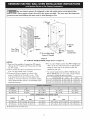
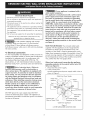
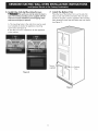
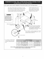
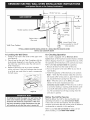
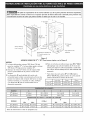
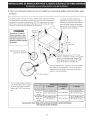
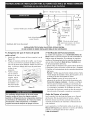
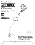
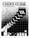
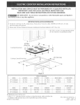
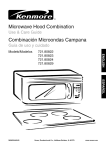
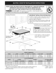
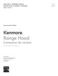
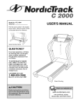
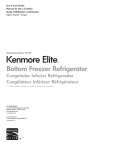
iNSTALLATiON AND SERVICE MUST BE PERFORMED BY A QUALiFiED
iNSTALLER, iMPORTANT:
SAVE FOR LOCAL ELECTRICAL iNSPECTOR'S USE.
READ AND SAVE THESE iNSTRUCTiONS
FOR FUTURE REFERENCE.
United
States
FOR YOUR SAFETY: Do nat store or use gasollne or other flammable
vapors and liquids in the vicinity of this or any other appliance.
Canada
Your new wall oven has been designed to fit a limited variety of cutout sizes to make
the jab of installlng easier. The first step of your installatlon should be to measure your
current cutout dimensions and compare them to the cutout dimensions chart below far
your model. You may find lltfle or no cabinet work being necessary.
Do not remove spacers (if equipped)
on the side walls and/or an the back of the
built-ln oven. These spacers center the oven in the space provided. The oven must be centered to
prevent excess heat buildup that may result in heat damage or fire.
NOTES:
|. Bose must be capable of supporting
150 pounds (68 kg) for 27"
and 200 pounds (90 kg) for 30" models.
2. Allow
depth
at least 21" (53.3cm)
when it is open.
clearance
in front of oven for door
models
1" (2.5 cm)
Min.
3. Dimension G (cutout depth) is critical
to the proper installation of the builtin oven. If the oven decorative
trim
<L
does not butt against the cabinet, or if
I
noise is heard on convection
models,
B
verify dimension G to assure it is the
I
required depth,
t
4. For o cutout height greater
than 2713/16" (70.6cm)
odd
......._
H
|
i|
.
.
one 2 (5cm) wide wood shim
of appropriate
height to each
side of the opening under the
appliance
side roiis.
Suggested distance from floor
is 31" (78.7cm).
Minimum required
distance
31"*
._--'"
Doc)r Open
(see
note 2
2" (5 crn) Wide Wood
Spacer if Needed
is 4 1/2" (11.4cm)
Elecfrlcal
Junction Box
Figure |
27"
and 30"
Single Wall Ovens (Double
ovens see Figure 2)
27" (68.6cm)
27 (68.6)
29t/16(73.8)
24s/8 (62.5)
241/2 (62.2)
30" (76.2cm)
30 (76.2)
29t/16(73.8)
28t/4 (71.8)
241/2 (62.2)
CUTOUT DIMENSIONS AND CABINET WIDTH
F
H
MODEL
G (rain.)
Min.
Max.
27" (68.6cm)
247/8 (63.2)
251/4(64.1)
30" (76.2cm)
281/2 (72.4)
29 (73.7)
Aii dimensions
I
Min.
Max.
231/2 (59.7)
275/_ (69.4)
281/2 (72.4)
271/8 (68.9) Min.
231/2 (59.7)
275/_ (69.4)
281/2 (72.4)
301/8 (76.5) Min.
ore in inches (cm).
P/N
318201544
(1005)
Rev. A
English - pages 1-8
Printed
in United
States
Espa_ol
- p6ginas
9-16
Do not remove spacers (if equipped) an the side walls and/or an the back of the
built-ln oven. These spacers center the oven in the space provided. The oven must be centered to
prevent excess heat buildup that may result in heat damage or fire.
1" (2.5 cm)
Min.
J
Hole
B
48 5/8"
H
for
Cable
(123.5cm)
11½"
(29.2
Door Open
_- Spacer
Electrlcal
Junction
Box
2" (5 cm) Wide Wood
Spacer if Needed
Figure 2
27"
AND
30" DOUBLE OVENS
(Single
Ovens see Figure
1)
NOTES:
I.
Base
must
(136 kg)
be capabie
for
27"
of
models
supporting
and
300
375
.
pounds
pounds
(170
kg)
for 30" models.
2. Allow
at least 21" (53.3 cm) clearance
oven
for
door
3. Dimension
proper
oven
depth
G (cutout
installation
decorative
cabinet,
verify
required
of
trim
or if noise
dimension
when
it is open.
depth)
is critical
the
built-in
does
not
is heard
G to
For Cutout height between 5113/16"(131.6 cm) and
51_s/16"(131.9 cm), you can order a larger inferior
to the
oven.
butt
on
assure
in front of
If the
against
convection
it is according
For a cutout height greater than 491,,_'' (125.1 cm)
add a 2" (5 cm) wide wood shim of appropriate
height to each side of the opening under the
appliance
side rails.
trim kit by calling
the
the Service
Stainless Steel
Center.
Black
White
models,
to the
dimension.
Trim
27"
903114-901S
903114-9010
903114-9011
Trim
30"
903114-910S
903114-9100
903114-9101
27" (68.6crn)
27 (68.6)
501/2 (128.3)
24s/_ (62.5)
24V2 (62.2)
30" (76.2cm)
30 (76.2)
50V2 (128.3)
28V4 (71.8)
241/'2(62.2)
CUTOUT DIMENSIONS AND CABINET WIDTH
F
MODEL
H
Min.
Max.
27" (68.6crn)
247/_ (63.2)
25V4 (64.1)
30" (76.2crn)
281/2(72.4)
29 (73.7)
All dimensions
are _n inches (cm).
G (rain.)
I
Min.
Max.
231/2 (59.7)
487/_ (124.1)
497/_ (126.7)
27_/_ (68.9) Min.
231/2 (59.7)
487/_ (124.1)
497/_ (126.7)
30_/_ (76.5) Min.
importantNotesto the Installer
1. Readaii instructions
contained
intheseinstallation
instructions
beforeinstallingthewalloven.
2. Remove
all packingmatedalfromtheoven
compartments
beforeconnecting
theelectrical supply
3. Electrical
to the waft oven.
3.
4.
Observe all governing codes and ordinances.
Be sure to leave these instructions with the consumer.
5.
6.
Oven door may be removed to facilitate
installation.
THESE OVENS ARE NOT APPROVED FOR
STACKABLE OR SiDE=BY=SIDE iNSTALLATION.
important
Note to the Consumer
Keep these instructions with your Owner's
reference,
iMPORTANT
required by your model, see the serial plate to find the
wattage consumption
and refer to table A to get the
circuit breaker or fuse amperage.
n_
Lessthan 4800W
Guide for future
injuries and can
Circuit
Recommended
Lessthan 4100W
20A
30A
4100W - 6200W
30A
7200W
- 9600W
40A
6200W
- 8300W
40A
and +
50A
and +
50A
8300W
aft governing
codes and local ordinances
Wire
sizes and connections
must conform
with
the fuse size and rating of the appliance
in accordance
with the American
National
Electrical Code ANSI/NFPA
No. 70-latest
edition, or with Canadian
CSA Standard
C22.1, Canadian
Electrical Code, Part 1, and local codes
and ordinances.
oven for warming
or heating
use of the wail oven without
can be dangerous.
An extension
cord should not be used
with this appllance.
Such use may result in a fire,
electrlcal shock, or other personal injury. If you need a
longer power cord you can purchase a 10' (3 m) power
cord kit #903056-9010
by calling the Service Center.
Refer to figure 1 or 2 for the dimensions applicable
to
your appliance,
and the space necessary to receive the
oven. The oven support surface may be solid plywood
or similar material,
however the surface must be level
from side to side and from front to rear.
2.
Height
with 2" (5 cm) wide wood
shims when needed to fit into an existing cabinet cutout
opening, when cutout height exceeds 2713/16" (70.6
cm) for the single wail oven or 491.4" (125.1 cm) for
the double
appropriate
Protection
20A
NOTE:
1. Carpentry
Oven
Rating Watts
208V
1. A 3-wire or 4-wire single phase 120/240
or 120/208
Volt, 60 Hz AC only electrical
supply is required on
a separate circuit fused on both sides of the line
(red and black wires). A time-delay
fuse or circuit
breaker is recommended.
DO NOT fuse neutral (white
wire). Only certain cooktop models may be installed
over certain built-in electric oven models. Approved
cooktops and built-in ovens are listed by the MFG ID
number (see the insert sheet included in the literature
package).
leaning or sitting on the door
can be adjusted
H
- 7200W
Observe
The electrlcal
power to the oven must
be shut off while llne connections
ore being mode.
Failure to do so could result in serious injury or death.
Oven height
Appliance
Circuit
Recommended
Table A
° This wahl oven must be electrically
grounded
in
accordance
with local codes or, in their absence,
with the National
Electrlcal Code ANSI/NFPA
No.70=
latest edition in United Sates, or with CSA Standard
C22.1, Canadian Electrical Code, Part 1, in Canada.
2. Adjusting
n
4800W
9600W
° Be sure your wall oven is installed and grounded
properly by a qualified installer or service
technician.
° Never use your wall
the room. Prolonged
adequate
ventilation
B
Protection
Rating Watts
240V
INSTRUCTIONS
Stepping,
I
Appliance
SAFETY
of this wall oven can result in serious
also cause damage to the wall oven.
Requirements
This appliance
must be supplied with the proper
voltage and frequency, and connected
to an individual,
properly
grounded branch circuit, protected
by a circuit
breaker or fuse. To know the circuit breaker or fuse
3.
wail oven (see Figure 1 or 2). Place shims of
height beneath the oven side rails.
3
These appliances
should be connected
to the fused
disconnect (or circuit breaker) box through flexible
armored or nonmetallic
sheathed cable. The flexible
armored cable extending
from the appliance
should
be connected
directly to the junction box. The
junction box should be located as shown in Figure
1 or Figure 2 and with as much slack as possible
remaining
in the cable between the box and the
appliance,
so it can be moved if servicing is ever
necessary.
A suitable strain relief must be provided to attach
the flexible armored cable to the junction box.
Electrical
Shock
Hazard
* Electrical ground is required on this appliance.
* Do not connect to the electrical supply until appliance
permanently
appliance
permanent
is
grounded.
* Disconnect power to the junction
electrical connection.
" This
(If your appliance
is equipped wlth a
white neutral conductor.)
This appliance
is manufactured
with a white neutral
power supply and a frame connected
copper wire.
The frame is grounded
by connection
of grounding
lead to neutral lead at the termination
of the conduit,
if used in USA, in a new branch circuit installation
(1996 NEC), mobile home, recreational
vehicles, where
Iocag code do not permit grounding
trough the neutral
(white) wire or in Canada, disconnect the white and
green lead from each other and use ground lead to
ground unit in accordance wlfh local codes, connect
neutral lead to branch clrcult=neufral conductor
in
box before making the
be connected
to a grounded,
metallic,
system, or a grounding
connector should
to the grounding terminal or wire lead on
must
wiring
be connected
the appliance0
* Do not use a gas supply line for grounding
the appliance.
usual manner
Failure to do any of the above could result in a fire,
personal injury or electrical shock.
In cold weather shipping and storage
conditions,
make sure that oven is in final location
at least three (3) hours before switching
on power.
Switching on power while oven is still cold may damage
the oven controls.
4° Electrical
see Figure 4. If your
appliance
is to
be connected to a 3 wire grounded
junction
box
(US only), where local code permit connecting
the
appllance=groundlng
conductor
to the neutral (white)
see Figure 3.
NOTE TO ELECTRICIAN:
The armored
cable
leads
supplied with the appliance
are UL-recognized
for
connection
to larger gauge household wiring. The
insulation of the leads is rated at temperatures
much
higher than temperature
rating of household wiring. The
current carrying
capacity
of the conductor
is governed
by the temperature
rating of the insulation around the
wire, rather than the wire gauge alone.
connection
It is the responsibility
and obligation
of the consumer to
contact a qualified
installer to assure that the electrical
installation
is adequate
and is in conformance
with
the National
Electrical Code ANSI/NFPA
No. 70latest edition, or with CSA Standard C22.1, Canadian
Electrical
Code, Part 1, and local codes and ordinances.
Where
local
grounding
Only)
Risk of electrical
shock (Failure to
heed thls warning
may result in electrocution or
other serious injury.) This appliance
is equipped wlfh
copper lead wire. If connection
is made to aluminum
house wiring, use only connectors that are approved
for joining copper and aluminum
wire in accordance
wlfh the National
Electrical Code and local code and
codes
permit
conductor
(see figure
1.
Disconnect
2.
In the
shown
neutral
the
appllance=
(white)
wire
(US
3):
the
junction
connect
connecting
to the
power
supply.
box:
appliance
in Figure
and
power
supply
cable
wires
3.
Cable from Power Supply
White
ordinances.
When installing connectors
having screws
which bear directly on the steel and/or aluminum
flexible conduit, do no tighten screws sumclently to
damage the flexible
conduit. Do not over bend or
excessively distort flexible
conduit to avoid separation
of convolutions
en exposure
of internal wires.
Wire
(Neutral)
_
_
I
\l
Red
DO NOT ground to a gas supply pipe. DO NOT
connect to electrical
power supply until appliance
is
permanently
grounded. Connect the ground wire before
turning on the power.
Black
:::........._--_-_------W"
;":_:_'- :<_ _
z/
_i
:
ires m
a--
/
'/'¢X'v-'A ) ........
i
j| --_Whit
/_
.......! S
"White Wire
/
Ground Wire
(Bare
or Green
---I
k_
_
(Neutral)
_........ U.L0-Listed Conduit
Wire)
,_L
Cable
from
Connector
appNance
Figure 3
3-WIRE GROUNDED JUNCTION
4
(or CSA
BOX
listed)
as
If oven
is used in a new branch circuit
5. Cabinet
installation
(1996 NEC), mobile home, recreatlonaJ vehicle, or
where local codes DO NOT permit grounding through
the neutral (white) wire, the appliance
frame MUST
HOT be connected to the neutral wire of the 4-wire
electrical system. (see figure 4):
1. Disconnect the power supply.
2. Separate the green (or bare copper)
appliance
cable wires.
Do nat lift the
Heavy
Failure to follow
to the unit.
Ground Wire
w
hite
w
Weight
Hazard
this instruction
can result in injury
or damage
1. Unpack the wall oven. Remove the bottom trim taped
on the oven side panel.
2. Find the 2 anti-tip mounting screws included in the
literature
package.
3. Insert the oven into the cabinet opening. Slide oven
inward leaving 11/2" (3.8cm) clearance
between the
oven and front of cabinet (see Figure 5).
Cable from Power Supply
_'__ J_
_'_
\p____c/_
by the door handle.
Use 2 or more people to move and install wall oven.
Wire
Red
oven
and white
3. In the junction box:
connect appliance and power supply cable wires as shown
in Figure 4.
Ground
Installation
ire
___'_
(Bare or Green-Wire)
J
Junction Box
j
S
_
_
ire
_
_- .... U.L.-Listed Conduit
_'
Connector (or CSA
Cable from appliance
listed)
Figure 4
4-WIRE GROUNDED JUNCTION BOX
Model
and Serial Number
Location
The serial plate is located along the interior side trim of
the oven and visible when the door is opened.
When ordering parts for or making inquires about your
oven, always be sure to include the model and serial
numbers and a Jot number or letter from the serial plate
on your oven.
cm)
clearance
between
Single Wall Oven Serial
Plate Location
unit
Figure 5
4.Pull the armored cable through the hole for it in the
cabinet and toward the junction box while moving the
appliance
inward.
5. Push the oven in and against the cabinet.
Double Wall Oven
Serial Plate Location
5
6 Install
the Anti-tip
Mounting
Screws
Z
The wall oven can tip when the door is
Install
the
Bottom
Trim
Place the top of the bottom trim over the side trim
tabs on each side of the oven below the oven door
open. The antl-tlp mounting screws supplied with the
wall oven must be installed to prevent tipping of the
wall oven and injuw to persons.
and fix it using the 2 screws supplied in the mounting
holes located on each side trim below the oven frame
(see
Figure
7).
A. The mounting holes in the side trims may be used
as a template
to locate the appliance
mounting
screw holes (see figure 6).
B. Use the two screws supplied to fix the appliance
to the cabinet.
Screws
supplied
Figura
u
6
Figure 7
6
Bottom
Trim
8. For typical
under
Only
counter
certain
cooktop
installation
models
of an electric
may be installed
oven models.
Approved
cooktops
ovens are listed
by the MFG
ID number
and
cooktop
installation
instructions
in the literature
and
product
built-in
code
package
oven
see Figure
Cabinet
over certain
built=in electric
(see the insert sheet included
built-in
and
side filler
panels
are nec-
essary
to isolate
the unit from
joining
cabinets.
Cabinet
height
should
allow
of approved
for the dimensions).
below.
ad-
side filler
for installation
cooktop
models
Approx. 3"
(Z5 cm)
To reduce
personal
the risk of
injury and tip=
ping of the wall oven,
the wall
oven must be
secured
to the cabinet
by mounting
36" Min.
(s)
(91.4 cm) Min.
brackets.
208/240
Volt junction
for built-in
box
oven.
Use 3/4"
(1.9 cm) plywood,
_-two runners,
must be capable
(68 kg) for 27"
pounds
(90 kg) for 30" models.
in wood
base minimum
23 cm), 2" (5 cm) from left side filler
4 1/2"
If no cooktop
cable
models
to junction
on
Base
of supporting
pounds
Cut an opening
armoured
installed
flush with toe plate.
150
and
200
9" x 9" (23 X
panel,
to route
box.
(11.5 cm) Max.*
is installed directly
over the oven unit, 5" (12.7 cm)
maximum
floor.
is allowed
above
the
27" (68.6cm)
Wall oven
247/8 '' (63.2cm)
30" (76.2cm)
Wail
oven
Min.
27t/4 '' (69.2cm)
(64.1cm)
Max.
281/2 (72.4cm)
281/2 (72.4cm)
Min.
27t/4 '' (69.2cm)
25V4"
29" (73.7cm)
281/2 (72.4cm)
TYPICAL UNDER COUNTER INSTALLATION OF A SINGLE ELECTRIC BUILT-IN OVEN
WiTH AN ELECTRIC COOKTOP MOUNTED ABOVE
7
Min.
Max.
Min.
Max.
Right Side of
Flexible
Appliance
Grounded
Flare
Union
Cabinet
Outlet
sides or
filler
panel
Manual
Wall
Cabinet
120v/60Hz
Shutoff
(To be accessible
Oven Cabinet
valve
Valve
for shut=off
operation)
TYPICAL UNDER COUNTER INSTALLATION OF A SINGLE ELECTRIC BUILT-IN OVEN
WITH
9. Leveling
1.
Install
(see
2.
a level
other.
in the
of the
upper
oven
Your
cavity
rack.
diagonally
Take
2 readings
in one
Use wood
is not
wail
shims
with
direction
under
the
and
wail
the
before
then
oven
the
to
oven
If
the
use wood
if you
level
shims
have
indicates
to
reach
that
Each
the
2. Turn
rack
a compromise
the
Bake
20
seconds
you
should
after
on and
oven
(some
electrical
inside
models)
and
has
been
will
continue
the
provides
electronlc
operating
to run
upper
part
cooling
components.
at high
after
rear
of the
oven
If the
oven
oven
is turned
the
Read
oven
(some
baking
8
more.
oven.
to your
Use &
oven
on,
the
will
the
upper
oven
is set for
elements
convection
stop
and
oven.
the
both
the
hot.
door
red.
)-When
and
oven
the
BROIL,
become
controls:
the
open
from
is set to
fan
oven
makes
or roasting,
running
cycle
fan
will
when
the
is opened.
Before
You
instructions
Call
or materials
Refer
Use
to your
numbers,
or
for
in your
and
that
workmanship
phone
(Refer
electronic
models
It may save you time
common
occurrences
fan
verify
You Call for Service
the
operating
off.
you
once
operation.
of the
function
coming
off: alternately
door
Before
the
inside
oven should
run. The convection
above
temperatures,
the
this
heat
the
in the
a convection
fan
that
controls
for
oven
turning
feel
Convection
A cooJlng
the
of the
that
- When
oven
Guide
to the
operation
- Verify
element
Figure 8
oven
checked
Guide.)
3. Verify
Broil
power
Oven
factory
it is suggested
Care
from
Electronic
has been
electronic
items
on the
Care
ovens.
However,
Use and
all
an
functions
of the
to the
with
of the
shipping.
1. Remove
a double
Operation
is equipped
operation
Refer
lower
oven.
level,
both
model
Control.
on the
in the
ABOVE
10. Checking
center
if necessary.
Repeat
for
rack
8).
placed
level
3.
oven
Figure
level
the
the Wall Oven
an
Place
A GAS COOKTOP
and
Service
Use
Checklist
and
Care
and
Guide.
expense.
The list includes
are not the result of defective
Care
in this
Guide
appliance.
for
Sears
service
call 1=800=4=MY=HOME®.
LA INSTALACION
Y EL SERViCiO DEBEN SER EFECTUADOS POR
UN iNSTALADOR
CALiFICADO.
IMPORTANTE: GUARDE
ESTAS
NSTRUCCIONES
PARA USO DEL INSPECTOR LOCAL DE ELECTRICIDAD.
LEA Y GUARDE ESTAS INSTRUCCIONES
PARA REFERENCIA FUTURA.
PARA SU SEGURIDAD:
y JJquldos inflamabJes
El primer
paso para su instaJaci6n
y compararJas
No aJmanece
en Ja pro×imldad
debe de ser eJ de medlr
con Jas que se indlcan
I. PoslbJemente
encontrar6
nl utillce
gasoJlna
de este o de ¢uaJquler
en eJ cuadro
que aJg_n trabajo
u otros
vapores
Canada
otro artefacto.
Jas dlmensiones
de dlmenslones
de ¢arpinterJa
Estados Unidos
de Ja apertura
deJ hueco de Ja figura
ser6
necesarlo.
No quite los separadores de los muros laterales o/y de la parte posterior del horno
empotrado. Estos espaciadores centran el homo en el espaclo provJsto. El homo debe estar centrado
para prevenir una concentracJ6n excesiva de caJor que podria resuJtar en da_os por eJ caJor o un
incendJo.
NOTAS:
1. La base debe poder sostener 150 libras (68 kg) para los modeJos 27"
y la base debe poder sostener 200 libras [90 kcj) para los modelos 30".
2. Deje par Io menos 21" (53.3 cm) de espacio libre para la
1" (2.S cm)
profundidad
de la puerta cuando esta abierta.
Min.
3. La dimensi6n
G (profundidad
del torte)
est6
para instaiar correctamente
el horno
de pared.
Si el adorno del armaz6n
del horno no topa contra el armario,
o si escuche un ruido, verifique si ia
B
dimensi6n G est6 en conformidad
con
ia dimensi6n requerida.
J
4. Para un corte de una altura mayor que
_
2713/16 '' (70,6 cm) agregar
..............
una....._una ae maaera ae _ to
(yea
cm) ae ancno para Iograr _a
altura apropiada
a cada lado
del orificio ubicado debajo de
la nota
minima
16"
_L
Orificio
-]_-__
|
H
I
para
el
Cable
cm)
|
_---.
.,
31"
(78.7 cm)
_
_.
.
2)
3"
(7.6 cm)
_
...
el_ctrica
los rieles laterales del accesorio.
Distancia sugerida desde ei suelo es 31" (78.7
La distancia
_rimordialj_
_
l
|
requerida
es 41/2 ''
J
cm).
de empatme
Espaciadorde Madera de :
(5 cm) de ancho, si es necesario
(11.4 cm).
Figura
Hornos simpJes de Pared de 27"
1
y 30" (Para hornos
dobJes, vet la Figura 2)
27" (68.6cm)
27 (68.6)
29_/_ (73.8)
24s/8 (62.5)
24V2 (62.2)
30" (76.2cm)
30 (76.2)
29_/_ (73.8)
28V4 (71.8)
24V2 (62.2)
DIMENSIONES DEL HUECO Y ANCHURA DEL ARMARIO
F
MODELO
27" (68.6cm)
30" (76.2crn)
Todas las dimensiones
Imprimido
en los Estados
Min.
H
G (rain.)
Max.
Min.
Max.
I
247/8 (63.2) i 25V4 (64.1)
23V2 (59.7)
278/_6(69.4)
28Y2 (72.4)
27_/8(68.9) Min.
28Y2 (72.4) I
23V2 (59.7)
278/_6(69.4)
28Y2 (72.4)
30_/8(76.5) Min.
29 (73.7)
se dan en pulcjadas
Unidos
(cm).
P/N
318201544
(1005) Rev. A
English - pages
Espa_ol - p6ginas
1-8
9-16
No quite
Estos espacladores
concentraci6n
los separadores
centran
el homo
de los muros laterales
en el espaclo
provlsto.
o/y de la parte posterior del homo empotrado.
El homo
debe estar centrado
para
prevenlr
una
exceslva de calor que podr_a resultar en da_os por el calor o un incendlo.
1" (2.5 cm)
Min.
Orificio
i
B
Puerta
(vea
para el
Cable
3" (7.6 cm)
Max.
Abierta
la nota
2)
et_ctrica
Espaciador
de Madera
2" (5 cm)
de ancho,
de
empatme
de
st es
necesario
Figura 2
HORNOS
DOBLES DE 27" Y 30" (Para hornos slmples, vet la Figura
1)
NOTAS:
4. Para un corte de una altura mayor que 491.,_'' (125.1
cm) agregar una cuba de madera de 2" (5 cm) de
ancho para Iograr la altura apropiada
a cada lado
del orificio ubicado debajo de los rieles laterales del
accesorio.
1. La base debe poder sostener 300 libras (136 kg)
para los modelos 27" y ia base debe poder sostener
375 libras (170 kg) para los modelos 30".
2. Deje por io menos 21" (53.3 cm) de espacio iibre
para ia profundidad
abierta.
de ia puerta
cuando
esta
Para altura de corte entre 5113/10 (13|.6 cm) y
511s/16'' (131.9 cm)_ puede ordenar el corte grande
inferior Ilamando
al centro de Servicio.
3. La dimensi6n G (profundidad
dei corte) est6
primordial
para instaiar correctamente
ei horno de
pared. Si ei adorno dei armaz6n dei horno no topa
contra ei armario, o si escuche un ruido, verifique
si ia dimensi6n G est6 en conformidad
con ia
dimensi6n
Acero
requerida.
Inox.
Negro
Btanco
Corte
27"
903114-901S
903114-9010
903114-9011
Corte
30"
903114-910S
903114-9100
903114-9101
!iiiiiiil
iiiiiiiiiiiiiii!!iiiiiiiiii
ii!!!i
i!iii!i!!i
!i!!!!!!iiiiiiiiiiiiii
iiiiiiiiiiiiiiiiiiiiiiiiiiiiii!!ii!iiiil
iiiiiiiiiiiiiiiii!!!!!iiiiii
ii!i!i!!!!!!!!!!!!!i!ii
!!iii
!ili!!
!ii!!!!!!!!!!!!!!ii!iiiiii
iiiii
iiiii
iiiiii
iiiii
iiiii
iiiii
iiiili
iilil
!!ii!
!ii
iii!!iii
iiiiii
iiiii
iii
iii!ii!
!il
i!iiiii
!ii!!i
iiiiii
iiiii
iiiii
iiiii
iiiii
iiill
iiiiii
iiiii
iiiii
iiiii
iiiiiiiiiiiiiiiiiiiiiiiiiiiiiiiiiiiiiiii
iiiiii
ii_i_!!_!!!!!iiiiiii!iiiii!i!i!i!i!i!!_!_!i!_!i!_!!i_i_!!i!_!_i_!i_i_
ilili_i!_i_iiiiiii_i_i_iiiiiiiiiiiiiliiiiiiiiiiiiiiiiil
iiiiiil
iiiiiiiiiiiiiiiiiiiiiiiililil
iiiii!i!i!i!i!!!!i!i!iiiiiiii
iiiiiiii
iiiiiiiiiiiiiiiiiiii
iiiiiiiiiiiiiiiiiiiiiiiiiiiiiiiiiiiiiiiiiiiiiiiiiiiiiiiiiiiiiiiiiiiiiiiiiii
iiiiii
iiiiiiiiiiiiiiiiiiiiiiiiiiiiiiiiiiiiiiiiiiiiiiiiiiiiiiiii
iiiiiiiiiiiiiiii!i!i!i!!i!!i!!i!!i!!
i!i!iiiiiiiiiiiiiiiiiiiiiiiiiiiiiiiiii
iiiiiiii
iiiiii__iiiiiiiiiiiiiii__iiiiiiiiiiiiiiiii__iiiiiiiiiiii
iiiiiiiiiiiiiiiiiiiiiiiiii!ii!ii!iiiii!ii
iii!iiii!!!i!ii!i!ii!iiiiiiii
iiiiiii
iiiiiiiiiiiiiiiiiiiiiiiiiiiiiiiiiiiiiiiiiiiii
iiiiiiiiiiiiiiiiiii!!!!ii!iiiiiiiiiiiii
iiiiiiiiiiiiiiiiiiiiiiiiii!ill
iil:i_i_i_i_i,!ii_ii_i_i!i
ii_ii!i
'ii_!
!i!i'ii_i_i!i_!_!!!!_!:_iiiiil;i_ii_i_iii!!iiiiiiiiiii_i,i_ii_ii_i_i'i
i!i_i_!i_!i_!i'i'iii!i!i_!iiii!i
_i,i,!ii,!ii_iiii!i!ii'ii!iii
!iii_iiiiiiiiii_ii_i
!i_i!i
ii_iiiii_ii:i
ii_!i_!i,!i!
ii_i_i!!iiiii!i
ii_ili
_i_!'iiii_i,ii_iiiii_i_i_i:_i!ili
ii:!i!i!i_iiii!
i_
i!i!i
ii!ii
ii!ili
ilii
_i!iiili
iliilill
i!iiii!i:!_i_i_iii!i!i:i:iiiiiii'_i_i
i!i!_iil
i!i!i!ii
ii__iii_i
i_
ii!ii_i,!iii!iiiii
iilJ
ii!iiii
iii!il
i_iiili
_iiiii!,i:iill
i!iii
iiii!i
i_!i
i_iiiiiiiii
iiiii
ii!i'
!ii!_i:iiii_i!_i_:
!_!!ii!!iiii!i_i,!ili_i
ilii_i_
i'_ili
ii!!i
ii!!
i!!ii!!i
i_i!ill
iiiiiiii
iii!_i_!_i,!_!_!_!_i_!_ii_i
i_
i_i_i_i
ii!i'i_ilil;_i
_i_i!ill
ii_i_,!i_i_i!iiii_i
_i
iiii!i_i_!iiiiiii_
iii!ii
__!!ili
iiii!ii
ii!iii
ii__!iiiilil
i _i_i_ii_iii
!ii'_!iiiii_i
iil;_i_i_!
!iiii!ii
_iiii!i
ilii!
iiii'
ii!iiiiii,i
_ii_,!!_i_iii_iiiii_i
_i
iiililili
!iiiii
_!!'i
iililii!i!iiiii!ii!iii!iiii
iilili
!iiiilil_ i_!iii!!iii!i
i!iii!iiiii
iliii!iii!iii
ii!!!!i!
iii!!!'_:i
iiii_iii!i
i!iiliiiiii!i!i_
'_!_
i_i!ii
i_ili_!i!!iill
iliiiiiii:iiiiii_ilili_i
iliiiiiiii_'i
iii!!iii!!!ii!
!iiiiii!iii!i
_i
_i!iiiiiiiii_iii
i!ili!!_!i
iiiilil
!i_!i!!i_
_i_
iii!i!i_i_17!_
i_ii!!i_!,!!i
iil_!i!_!ii!:
'!iiiiiii!ill
iiiiiiiiiiii!i
iiili!
iiiiiiili
iiiiiiliiiiif!
27" (68.6cm)
27 (68.6)
501/2 (128.3)
24s/8 (62.5)
241/2 (62.2)
30" (76.2cm)
30 (76.2)
501/2 (128.3)
28t/4 (71.8)
241/2 (62.2)
DIMENSIONES DEL HUECO Y ANCHURA DEL ARMARIO
F
MODELO
N
G (Min.)
Min.
Max.
27" (68.6cm)
247/8 (63.2)
25V4 (64.1)
30" (76.2cm)
28V2 (72.4)
29 (73.7)
Todas las dimensiones
se dan en puicjadas
I
Min.
Max.
231/2 (59.7)
487/8 (124.1)
497/8(126.7)
27_/8 (68.9) Min.
231/2 (59.7)
487/8 (124.1)
497/8(126.7)
30]/8 (76.5) Min.
(cm).
10
Notas importantes
para el instalador
I. Lea todas las instrucciones contenidas
antes de instaJar el horno.
3. Requerimientos
en este manual
2.$aque todo el material usado en el embalaje del
compartimiento
dei homo antes de conectar ei
suministro elSctrico o de gas a ia estufa.
3.Observe todos los c6digos y regiamentos pertinentes.
4.Deje estas instrucciones con ei consumidor.
5. La puerta del horno se puede retirar para facilitar la
instalaci6n.
6.ESTE HORNO NO ESTA APROBADO
PARA LA
INSTALACI6N
APILABLE O DE LADO A LADO.
Nora importante
m
Grados
del usuario
para
" Aseg_rese de que su homo de pared sea instalado y
puesto a tlerra de farina apraplada
par un instalador
callflcado
a par un t_cnlco de servlclo.
• Este homo de pared debe set el_ctrlcamenie
puesto
a tlerra de acuerdo con los c6dlgos locales o, en su
ausencla, con el C6dlgo El_ctrlco Naclonal ANSI/
NFPA No. 70-Oltlma
edlci6n en los Estadas Unldas, o
el C6dlgo El_ctrlco Canadlense CSA Standard C22.1,
Part 1, en Canad6.
serlas
• Nunca
use su homo de pared para calentar
habltaci6n.
El usa prolongado
de ia estufa
ventilaci6n
adecuada
puede ser peligroso.
La corrlente
=
_
de!
e!ectrodom_stico
"
Se recomienda
una protecc!6
al circuito
n
208V"
20A
Menos de 4100W
20A
4800W
- 7200W
30A
4100W
- 6200W
30A
7200W
- 9600W
40A
6200W
- 8300W
40A
and +
50A
and +
50A
8300W
NOTA: Los tama_os y ias conexiones deJ alambre deben
conformarse
con el tama_o del fusible y el grado de la
aplicaci6n
de acuerdo con el c6digo El_ctrico Nacional
sabre la
puerta de este homo de pared puede causar
leslones y da_os al homo de pared.
una protecci6n
al ckcuito
de Vatios
Table A
Observe fodos los c6digos que gobiernan y ordenanzas locales
1. Un cable de 3 o 4 alambres
monof6sico
120/240
o
120/208
voltios, 60 hertzios es la 0nica fuente el_ctrica
que requiere en un circuito separado en ambos lados de
la linea (alambre negro y alambre rojo) (se recomienda
un fusible o un interruptor de retraso de tiempo). No
funda a cable neutro (alambre blanco).
Se debe de
tener precauci6n al combinar un horno de pared y una
cubierta, refi_rase a la placa de seria de cada uno de
los aparatos.
DE SEGURIDAD
o sentarse
I
Grados
Menos de 4800W
9600W
Pisar, apoyarse,
m
Se recomienda
240V
INSTRUCCIONES
IMPORTANTES
de
Vatios de!
e!ectrodom_stico
al consumidor
Conserve estas instrucciones y el manual
referencia futura.
El_ctricos
$e debe proveer el voltaje y la frecuencia
apropiados
a
este electrodom6stico,
y conectarse a un circuito individual
correctamente
puesto a tierra, protegido por un interruptor
o un fusible. Para conocer
el interruptor o fusible que
requiere
su modelo, vea la placa serial para encontrar
la consumaci6n
del vatiaje y refierase al cuadro
A para
encontrar el amperaje del interruptor o fusible.
Americano
el est6ndar
canadiense,
una
sin ia
ANSI/NFPA
No. 70- ultima edici6n,
o con
CSA canadiense
C22.1 , c6digo el_ctrico
parte 1, y c6digos y ordenanzas locales.
No se debera
el_ctrlca al homo debe estar
usar
extenslones
para
enchufar este electrodorn_stlcoo Esto podria causar un
incendlo, choque el_ctrlco u otto tlpo de da_o personal. Si
usted necesita un cable mas largo_ puede ordernar un cable
de 10" kit 903056-9010
Ilamando al centro de Servicio.
apagada mlentras se hacen las conexlones de lineas. Si
no se apaga, da_os serlos o la muerte podrian resultar.
1. Carpinteria
Consulte la Figura 1 o la figura 2 para conocer las dimensiones pertinentes al modelo de su homo y al espacio
necesario en el que poner el horno. La superficie donde
se va a apoyar el homo debe de ser de madera contrachapada s61ida u otro material similar y, sobre todo, la
superficie tiene que estar a nivel, de lado a lado, y de
atr6s hacia adelante.
2. Este electrodom_stico
debe conectarse
a la caja de
fusibles (o de cortocircuito),
por medio de un cable
blindado flexible o un cable con forro no met61ico. El
cable blindado flexible que va desde el electrodom_stico
debe de estar conectado
directamente
a la caja de
empalme. La caja de empalme debe de estar Iocalizada
en el lugar que se indica en la Figura 1 o 2, dejando
tanto exceso de cable como sea posible entre la caja y
el electrodom_stico,
de forma que asi el electrodom_stico
se pueda mover f6cilmente, si fuera necesario para hacer
una reparaci6n.
3. Se debe de usar un conector que reduzca la tirantez de
una forma adecuada para unir el cable blindado flexible
a la caja de empalme.
2. Ajuste de la altura del homo
La altura del homo se puede ajustar con cu_as de madera de
2" (5 cm) de ancho, donde sea necesario, para que quepa en
un gabinete o abertura existente, cuando la altura del corte
es superior a 2713/16" (70,6 cm) en el caso del homo 0nico
de pared o 491,,_" (125.1 cm) en el caso del homo dobJe
de pared (ver la Figura 1 6 2). Colocar las cu_as de altura
apropiada
debajo de los rieles laterales del horno.
11
(Si su electrodom_sfico est6 equlpado
con un conductor neutro blanco.)
Este electrodom_sfico
est6 fabrlcado con un sumlnlstro
Riesgo de choque el_ctrlco
* Una puesta a tierra se requiere en este aparato.
* No Io conecte a la corriente
el6ctrica
basra que el aparato
haya
sido puesto a tierra.
*
Desconecte
la corriente
el6ctrica
a la ¢aja
antes
de hacer
la conexi6n
el_ctrica.
el_ctrlco neutro blanco y un alambre de cobre conectado
al armaz6n.
El armaz6n
esta puesto a tlerra
pot un
enlace de la conexi6n a fierra con la conexi6n del neutro
al final de la IJnea el_ctrlca, sl es usado
unldos una nueva instalaci6n de clrculto
de empalmes
* Este aparato debe estar conectado con un sistema de
alambres puesto en tierra, met61ico¥ permanente o un
conector de puesta a tierra debe conectarse al terminal de
puesta a tierra o el alambre conductor en al aparato.
* No utilice el suministro de gas para hacer la puesta a
tierra.
La falta de cualquiera de las instrucciones mencionadas
podria resultar en un incendio, choque el6ctrico o lesiones
personales.
En cuanto
despacho
a las condiciones
y aimacenamiento
de que el horno
final
tres (3) horas antes de encenderlo.
el horno cuando
controles.
(1996 NEC), casa rodante, vehiculos
recreaclonales,
o
donde los c6dlgos locales no permltan
poner a tlerra
medlante el neutro (blanco) o en Canada, desconectar
la conexi6n
blanca de la verde y utillzar
la conexi6n
a tlerra para poner a tlerra la unldad
de acuerdo
a
los c6dlgos
locales, conectar
el neutro al clrculto
de
blfurcaci6n=
conductor
neutro de manera usual. Vet
Figura 4. Si su
a una caja de
(en los estados
locales permltan
electrodom_sfico
de
en el invierno, asecjOrese
llecjue a su destino
da_ar
NOTA
los
obiigaci6n
asecjurar
forrna
tiene la responsabilidad
de utilizar
El_ctrico
un instalador
que la instalaci6n
adecuada
Nacional
ANSI/NFPA
y
calificado,
ei_ctrica
y est6 conforrne
en los Estados Unidos,
CSA Standard
personal
para
est6 hacha
AL ELECTRICISTA:
Los conductores
de cable
blindados
provistos con este artefacto
son aprobados
por UL para la conexi6n al alarnbrado
de casa de un
calibre mayor.
El aislarniento
de los conductores
est6
calificado
para ternperaturas
rn6s altas que las del
alarnbradodela
casa. La capacidad
decorrientedel
conductor
est6 gobernada
por la calificaci6n
de la
ternperatura
del aislarniento
alrededor
del alarnbre en
vez de solarnente el calibre del alarnbre.
4. Conexi6n el ctrica
El usuario
electrodom_stlco
va a set conectado
conexi6n
puesta a tlerra
de 3 cables
unldos solamente),
donde los c6dlgos
conectar el conductor de poner a tlerra=
con el neutro (blanco) vet Figura 3.
corno rninirno
Si se enciende
a0n est6 trio, se pueden
en los estados
de blfurcaci6n
de
con el C6dicjo
No. 70-01tirna
o el C6dicjo
El_ctrico
edici6n
Donde los c6dlgos locales permltan conectar el
conductor de puesta a fierra del electrodom_sfico
al
neutral (blanco)
(Solamente en los Estados Unldos)
(vea figura 3):
1.
Desconecte el surninistro el_ctrico.
Canadiense
C22.1, Part 1, en Canad6.
Riesgo de choque el_ctrlco
(El no prestar atenci6n a esta advertencla
puede
resultar en electrocuci6n u offas leslones graves)Este
elecffodom_stlco est6 equlpado con alambre de cobre.
Si se va a conectar con cableado de alumlnlo del hogar,
utillzar _nlcamente
conectores que est6n aprobados
para unlr cobre y alumlnlo de acuerdo al C6dlgo
Naclonal El_ctrlco (NEC pot sus slglas en ingles) y leyes
y c6dlgos locales. AI instalar conectores con tornillos que
2.
En el caja de juntas: conectar el aparato y los cables
residenciales corno se rnuestra en la ficjura 3.
Cable
desde el suministro
de energfa
/_
Alambre
roio
empujen dlrectamente contra el acero y/o alumlnlo del
conducto fiexlble, no apretar los tornillos suficlentemente
que da_en el conducto fiexlble. No doblar de mc_so
deformar el conducto fiexlble para evffar separar el
esplral y descubrlr los alambres infernos.
egros
i
._-----
......
Caja de
empalmes
]
NO conecte el alarnbre puesto a tierra a una tuberia de
surninistro de gas. NO conecte el surninistro de enercjia
el6ctrica hasta que el electrodorn6stico
haya sido
perrnanenternente
puesto a tierra. Conecte el alarnbre
de puesto a tierra antes de enchufar por prirnera vez el
electrodorn_stico.
A amb everde
/
o desnudo
_/
_L"---2
\
Alambre
desnudo
Conductor
de
uni6n listado-UL
Cable
Figura
de la estufa
3 - CAJA
DE 3 ALAMBRES
12
CSA)
DE EMPALMES
PUESTA A TIERRA
(o
Si el horno se usa en una instalaci6n
5. Instalaci6n
de circuito de
ramal nuevo (1996 NEC), en una casa rodante, en un
vehiculo para recreaci6n o sl los c6digos locales NO
permiten la conexi6n a tierra a tray, s del cable neutral
(blanco), el armaz6n
del electrodom&sfico
NO TIENE
QUE estar conectado al alambre
neutro del slstema
el_ctrlco de 4 alambres.
(ver figura
1. Desconecte el suministro elSctrico
Separe
el aJambre verde (o cobre desnudo)
aiambre bianco dei electrodomSstico.
3.
En ei caja de juntas: conectar ei aparato y los cables
residenciaies como se muestra en ia figura 4.
Alambre
2. Buscar los tornillos
literatura.
Alambre _1_
1
que se inciuyen en el paquete
de
3. Insertar el horno en la abertura del cjabinete. Deslizar
el homo hacia dentro dejando 11/2'. (3,8 cm) de
espacio libre entre el homo y la porte delantera del
cjabinete (ver la Ficjura 5).
nco
_
nA_gr%_re
_<!Alambre
blanco
Caja de
Conductor
empalmes
uni6n listado-UL
Cable
de la estufa
Figuro 4- CAJA
DE 4 ALAMBRES
Ubicaci6n
de la puerto.
1. Desembalar el horno de pared. Extraer la cjuarnici6n
inferior y los 2 tornillos unidos con cinta al panel
lateral del horno.
de energfa
desnudo _
J
per la manija
Peligro de Peso Pesado
* Use 2 personas o m6s para mover e instalar el homo
de pared.
" Si no cumple con esta instrucci6n, puede resultar en
leslones personales o dafios al homo de pared
y el
Alambre
Alambre
verde o
desnudo
el homo
4):
2.
Cable desde el suministro
No levante
del Gabinete
de
(o
CSA)
DE EMPALMES
PUESTA A TIERRA
del nOmero de modelo
y de serie
La placa con el n6mero de serie est6 ubicada en la
guarnici6n interior lateral del homo y se puede ver
cuando se abre la puerta.
Cuando haga pedidos de repuestos o solicite
informaci6n con respecto a su horno, est_ siempre
seguro de incluir el n6mero de rnodelo y de serie y el
nOmero o letra del Iote de la placa de serie de su horno.
p_
1/2" (3.8 cm)
distancia
entre
la unidad y el
gabinete
Modelos
con un solo homo-
la placa
de serie est6
ubicoda
oqui.
Figura 5
4. Empujar el cable biindado a troves del orificio del
cjabinete y hacia la caja de paso mientras se desiiza
el accesorio hacia adentro.
Modelos
con un homo
101oco de serie
doble-
est6 ubicoda
la
5. Empujar el horno hacia adentro
cjabinete.
oqui.
13
yen
contra del
6. Instalaci6n
de los tornillos
de montado
Z Instalaci6n
El home de pared puede incllnarse
cuanda la puerta esta ablerta.
Los saportes de
mentaje que vlenen con el homo de pared deben
de estar ajustadas
al armarla y al aparato para
evltar que el homo de pared se incline y acaslane
quemaduras graves.
A. Los Ioarrenos en las molduras laterales pueden ser
usadas como gu[a para Iocalizar
los tornillos de
montado de la unidad (figura 6).
B. Use los dos tornillos proporcionados
para colocar
la unidad en la cabina.
Colocar
de la Guarnici6n
la parte superior
sabre las leng_etas
de la guarnici6n
laterales
la puerta del horno_ y fijarlas
provistos
con los orificios
Inferior
inferior
del horno_ debajo
de
usando los 2 tornillos
de montaje
ubicados
a
cada lade del marco del homo (ver la Figura 7).
Z
Tornillos
Guarnici6n
provistos
Inferior
Figura 6
Figura 7
14
8. Para una instalaci6n
fipica
de un horno el_ctrico
incorporado
debajo
del mostrador,
v_ase
la figura.
$61o ciertos modelos de tapas de cocina se pueden instalar
de hornos el_ctricos
mencionan
planilla
empotrados.
sobre ciertos modelos
Las tapas de cocina y los hornos empotrados
por su nOmero de identificaci6n
que se incluye en el paquete
MFG ID y c6digo
de literatura
ci6n de la cocina donde est6n detalladas
de producto
y las instrucciones
Los paneles
se
gabinete
(ver la
unJdad
de instala-
altura
las dimensiones).
debe
de relleno
de los gabinetes
adyacentes.
del relleno
permitir
lateral
nacJ6n deJ homo
la
La
del gabinete
la instalaci6n
de modelos
aprobados.
Approx. 3"
(7.5 cm)
el riesgo de
lesiones personales
del
para aislar
de tapas de ¢ocina
Para reducir
laterales
son necesarios
y incli=
de pared,
_ste debe
asegurarse
gabinetes
mediante
a los
soportes
36" Min.
de montaje.
(91.4 cm) Min.
208/240
caja
para
de empalme
hornos de pared
Instale contrachapado
de 3/4"
dos correderas_
nivelado
inferior. La base debe
izquierdo
cable
4 1/2"
* Si no se instala ninguna
cina directamente
del homo,
m6ximo
sobre
se permite
tapa
sostener
libras
(68 kg) para
libras
(90 kg) para los modelos
Corte una abertura
en el fondo
poder
deJ panel
a la caja
los modelos
de 9" X 9"(23
del contrachapado,
Jlenador,
(1.9 cm)
con la parrilla
150
27" y 200
30".
cm X 23 cm) (minimo)
a 2" (5 cm) del Jado
para poder
encaminar
el
de empalme.
(11.5 cm) Max.*
de co-
la unidad
un espacio
de 5" (12,7 cm) sobre el
piso.
27" (68.6cm)
Horno de
247/8 '' (63.2cm)
251/4 '' (64.1cm)
Min.
Max.
231/2 '' (59.7cm)
27t/4 '' (69.2cm)
Min.
281/2 (72.4cm)
Max.
pared
30" (76.2cm)
Homo
de
281/2 (72.4cm) Min.
29" (73.7cm)
231/2 '' (59.7cm)
27t/4 '' (69.2cm)
Min.
281/2 (72.4cm)
Max.
pared
INSTALAClON
TJPICA DEBAJO DE LA MESADA DE HORNO SIMPLE EMPOTRADO
CON TAPA DE COCINA MONTADA
15
÷
4"(10 cm)
5" Max.
6 1/2"
(12.7 cm)
Min.
(16.5 cm)
Adaptor
de gas
Lado dereTomacorriente
Conector
flexible
para
Adaptor
puesto a tierra
de 120Voltios
cho del ga-
binete
de gas
/60Hz
ReguJador de
Lados del gabinete_V
o panel
Gabinete
Ilenador
resi6n
V61vuJa de cierre manual
tenet acceso a Ja vd_ivuJa
de cierre manual)
(para
det horno de pared
INSTALACI6N TJPICA PARA UNA ESTUFA DE GAS ENCiMA
DE UN HORNO DE PARED INSTALADO DEBAJO DEL MOSTRADOR
9. Aseg_)rese
est_
I.
2.
Z Verificaci6n
de pared
Instale una rejilla al centro del horno superior (vea la
Ficjura 10).
Poncja un nivel por encima de la rejiila.
Lea 2 veces,
una vez con el nivel a la posici6n de lado a iado, y
otra vez de atr6s hacia adelante. Utilice trozo de mao tubas por debajo
niveiar, si sea
necesario.
Vueive a empezar en el horno
inferior. Si el nivei
muestra
f6brica antes del despacho. Sin embarcjo, le sucjerimos
verificar el funcionamiento
de los controles electr6nicos
una vez m6s. Consulte la Guia de Uso y Cuidado
ver el funcionamiento
del horno.
.......f:--...... .......
i
i
rejilla no esta a
nivel, utilice trozo
de madera o tuBas para componer ambos hornos.
para
1. Extraer todos los elementos de la parte interior del horno.
2. Encender el horno (Consular la Gufa de Uso y Cuidado.)
3. Verificar el funcionamiento
de los controles electr6nicos
del homo:
del homo de pared para
que ia
del funcionamiento
Su modelo est6 equipado
con un Control Electr6nico de
Homo. Cada una de las funciones ha sido controlada
en
a nivel
dera
3.
de que el homo
- ..............
Figura 10
Hornear - Verificar que esta funci6n caliente el horno. Veinte
minutos despu_s de encender el horno_ abrir la puerta y ver si
se siente que el calor emana desde su interior.
Asar= Cuando se pone ei horno para asar, el
elemento de arriba del horno debe de ponerse rojo.
Convecci6n (aJgunos modeJos) = Cuando se conficjura
el horno para horneado o asado por convecci6n, los
dos elementos se encienden y apacjan en forma alterna
y se enciende el ventilador.
El ventilador de convecci6n dejar6 de funcionar cuando se abre la puerta del
homo durante el horneado o asado por convecci6n.
Antes
an ventilador
ublcado dentro de la parte trasera
superior arrlba del homo (en aigunos modelos)
permlte la refrlgeraci6n de los componentes
ei6ctrlcos
y electr6nlcos de enfrlamlento. St el homo ha estado
funclonando a alias temperaturas,
el ventilador
segulr6 funclonando despu_s de apagar el homo.
de liamar
Lea la secci6n
aJ servicio
Lista de Antes de llamar
en su Manual
del Usuario. Esto le podr6 ahorrar tiempo y cjastos.
Esta lista incluye ocurrencias
comunes que no son el
resultado de defectos de materiales
o fabricaci6n
de
este artefacto.
Lea ia cjaranfia y ia informaci6n sobre ei servicio en su
Manual del Usuario para obtener el nOmero de tel_fono
cjratuito y la direcci6n del servicio o llama
|=888=SU=HOGAR sM.
16