1
Installation
Built-In
Dishwasher
Instructions
If you have questions, call
www.Sears.com
1-800-4-MY-HOME®(US)
BEFORE YOU BEGIN
Read these
instructions
or visit
our
IMPORTANT
completely
and
allow
carefully.
removal
from
or
be installed
the enclosure
to
if service
is required.
IMPORTANT
- Observe
all governing
codes
and
ordinances.
to Installer
instructions
use.
• Note
MUST
- The dishwasher
for future
If you
• Note
at: www.Kenmore.com
website
- Be sure to leave
for the consumer's
to Consumer
your Owner's
• Skill Level requires
Proper
- Keep
mechanical
installation
Product
is not covered
and local
these
instructions
and electrical
is the responsibility
failure
under
a damaged
contact
your
Optional
Accessories
available
custom
dishwasher,
dealer
- See the Owner's
panel
you should
or builder.
Manual
for
kits.
inspector's
with
Manual for future reference.
Installation
of this dishwasher
basic
installer.
these
received
immediately
skills.
of the
due to improper
FOR YOUR SAFETY
Read and observe
shown throughout
installations
glasses
all
described
or goggles
CAUTIONS
and
these instructions.
in this booklet,
should
WARNINGS
While
performing
gloves,
safety
be worn.
installation
the ELECTROLUX Appliance
Warranty.
• Completion
require
Time
-
1 to 3
more time than
Hours.
New
replacement
installations
WARNING
installations.
_[_
READ CAREFULLY.
KEEP THESE INSTRUCTIONS.
injury to persons, the installer must ensure that
To
the risk
of electrical enclosed
shock, fire,
or
the reduce
dishwasher
is completely
at the
time of installation.
Installation
Preparation
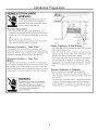
PARTS SUPPLIED:
Two#8
Phillips flat
dishwasher
head wood
to underside
screws,
of countertop
5/8"
TY
long to secure
(in literature
package).
Two Phillips head,
literature
color matched
toekick
screws (in
2 Wood
Screws
package).
2 Color Matched
Screw Type
Toekick Screws
Hose Clamp
MATERIALS YOU WILL NEED:
Ferrule, compression
external
water
thread
nut and
90 °
Elbow
on one end, opposite
(3/8"NPT
end sized to fit
Hand
Thread
Materials
for
Shut-Off
90 ° Elbow, Ferrule
seal tape
Air gap for drain
Seal
Tape
Nut
New
Installations
Nuts (3)
Thread
Valve
and Compression
UL Listed wire nuts (3)
Waste
Wire
supply)
Only:
hose, if required
tee for house plumbing,
Electrical
if applicable
Hot Water
Cable
line
(or Power Cord, if
Electrical
cable
or power
cord,
if applicable
Waste
Tee
applicable)
Screw type hose clamps
Strain relief for electrical
Hand shut-off
Water
CD
valve
line 3/8"
Coupler
connection
min. copper
for extending
drain
Coupler
Screw Type
line, if applicable
TOOLS YOU WILL NEED:
Level
1/4"
Phillips head screwdriver
and
1/4"
6" Adjustable
Phil_
nutdriver
and 5/16"
Nutdriver
Screwdriver
wrench
Level
Carpenters
Carpenters
square
Measuring
tape
Safety
Relief
Hose Clamps
Air Gap
5/16"
Strain
6" Adjustable
Square
...........
I,l,l,l,l,l,l,l,l,l,l,l,l
glasses
Flashlight
Tubing
Flashlight
Cutter
nch
Bucket to catch
water
when
flushing
the
line
Measuring
Gloves
For New
Tubing
Installations
Safety
Only:
Glasses
Bucket
cutter
Drill and appropriate
bits
Hole saw set
Hole Saw Set
Gloves
2
Tape
I
Installation
Preparation
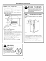
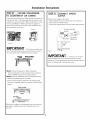
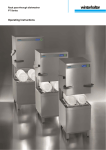
PREPARE DISHWASHER ENCLOSURE
•
The dishwasher
than
•
10 feet
must
The dishwasher
must
back,
not
and
be
in length
must
installed
so that
proper
drainage.
for
be fully
enclosed
support
any
dishwasher
adjacent
cabinet,
from
the front
dishwasher
opening.
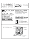
• The rough
cabinet
opening
17-5/8" to 18" wide.
must be at least
The opening
should be
,_/__
_
IDishwashelr
} i
of the
25-5/8"
for door
Figure
B
Figure B
24" deep and
32.5" max. height.
Note: ADA
tops
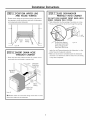
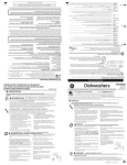
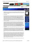
DRAIN REQUIREMENTS
Follow
local
•
Do
not
exceed
•
Do
not connect
•
drain
drain
must
(not
flow
Air
and
may
on
gap
distance
other
be connected
or
local
must
be used
18" above
32"
devices
to waste
minimum
codes
dishwasher.
following
Do
and
if waste
the
floor
line
high
ordinances
tee
with
drain
local
above
Will
the
_/___
F1
connection
is
Figure C
siphoning.
Method
depends
on answers
2 -
High Drain with Waste
a method
to attach
drain
hose
Tee or Disposer
to underside
of
to the
countertop.
or ordinances
tee
require
or disposer
an air
connection
be
_.___
gap?
less than
____
-m'-'ql_
18"
the floor?
installation
answer
1 MUST be
be
F1
back
have
a drain
loop
less than
32"
_2"
above
floor?
If
Tee or Disposer
an air
to prevent
or disposer
to prevent
installation
codes
waste
and
loop,
questions:
Will
counter-
to the
Provide
of drain
high
toekick
legs.
____
to drain.
from
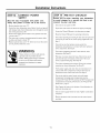
DRAIN PREPARATION
The type
the
Method 1 - Air Gap with Waste
lines
the
less than
34"
beneath
by adjusting
hose.
supplied)
into
(32-1/2")
installation,
be accomplished
ordinances.
10 feet
Dishwasher
depending
•
codes
dishwasher
gap
Clearancel:0rDoor
Opening2" Minimum
leveling
•
and
or
Plumbingand Electric Service
Must Enter ShadedArea
A
sides
and
wall
_
Figure
top,
is no more
of the enclosure.
other appliances.
Allow
25-5/8"
rain. clearance
•Square
and
Plumb
hose
/C0unteR0p
installed
into a corner,
allow 2" min. clearance
between
on the
part
CLEARANCES: When
32.5"
Underside0f
C0untert0p
to Floor
drain
used,
to
used,
Figure
ANY of
the
Otherwise
C or Figure
3 questions
either
above
Method
is
YES,Method
1 or Method
in.
III
Miin/
18
2 may
D.
Figure D
A
An
CAUTION"
air
waste
Failure
gap
tee
MUSTBEUSEDif
or disposer
to provide
lower
the proper
gap or 32" minimum,
draining
Install
waste
tee or disposer
manufacturer's
the
than
drain
drain
high drain
hose
18" above
is connected
height with
air
gap
according
to
to
the floor,
connection
and
instructions.
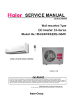
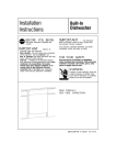
CABINET PREPARATION
•
air
Drill
areas
loop will result in improper
hole
of the dishwasher.
3
a
1-1/2"
shown
should
dia.
hole
in Figure
be smooth
in the
A for
with
cabinet
wall
the drain
hose
no sharp
edges.
within
the
connection.
shaded
The
Installation
Preparation
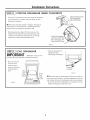
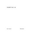
PREPARE ELECTRICAL WIRING
WARNING
/
FORPERSONALSAFETY:Removehouse
fuse
/
I
I
I
I
I
I
or open circuit breaker before beginning
installation.
Do not use an extension cord or
adapter
Electrical
",
\
\
\
1-1/2" Dia,
tole (Max.)
plug with this appliance.
Requirements
• This appliance
must be supplied
connected
to an individual
protected
by a 15 or 20 ampere
120V,60 Hz., and
with
properly
grounded
circuit
branch
breaker
from
Cabinet
circuit,
or time delay
fuse.
• Wiring
must be 2 wire
• If the electrical
supply
call a licensed
with ground.
does not meet the above requirements,
electrician
before
Grounding
Instructions
This appliance
must be connected
permanent
wiring
- Cable
grounding
conductors
terminal
White
FigureE
Cabinet
Direct
to a grounded
system, or an equipment
must be run with the circuit
equipment
proceeding.
• The wiring
metal,
grounding
floor
conductor
and be connected
Preparation
may enter the opening
within
the shaded
• Cut a 1-1/2"
to the
& Wire
his appliance
or breakdown,
by providing
must be grounded.
grounding
a path
plug must be plugged
and grounded
-
will
max. dia. hole to admit
the risk of electrical
for electric
into an appropriate
outlet
with local codes
direct
the drain
In the event of a malfunction
of least resistance
in accordance
• Cable
Power Cord
reduce
shock
current.
connections
cable.
The
wall is metal,
with a bushing.
may pass through
hose and hot water
the same hole as
line, if convenient.
the hole edge
NOTE: Power
cords with plug must pass through
must be covered
If cabinet
with a bushing.
a separate
hole.
The
that is installed
Electrical
and ordinances.
Electrical
Connection
connection
direct
shown in Figure
to Dishwasher
is on the right front of dishwasher.
connections
E. Cable
the cable
must extend
must be routed
a minimum
of
as
24"
from
the rear wall.
WARNING
connection
the electrical
wall is metal,
• For cable
The improper
either side, rear or the
hole must be free of sharp edges. If the cabinet
or lead on the appliance.
Instructions
from
area.
the hole edge must be covered
Grounding
Models
Routing
• For power
of the equipment
receptacle.
grounding
conductor
can result in a risk of
electric shock. Check with a qualified
electrician
or service representative
are in doubt that the appliance
is
properly grounded.
cord connections,
The power-supply
shall be installed
undercounter
if you
4
in a cabinet
space
in which
install
a 3-prong
receptacle
grounding
or on a wall adjacent
the appliance
type
for the appliance
to the
is to be installed.
Installation
Instructions
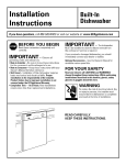
PREPARE HOT WATER LINE
• The line may enter from
shaded
either
BEFOREYOU BEGIN
side, rear or floor
within the
Locate
area shown in Figure F.
• The line may pass through the same hole as the electrical
cable
and drain
hose. Or, cut an additional
to accommodate
Jf power
the water
I-I/2"
and set aside the package
2 Phillips head countertop
2 additional
dia. hole
literature
line.
toekick
containing
mounting
screws (located
screws and
in the
package).
cord with plug is used, water line must not pass
through
power
cord hole.
STEP 1
I
I
I
I
I
///
I
CHECK DOOR BALANCE
To check the door balance,
\
hold the top of the dishwasher
\
firmly.
\
\
Increase
i
i
'//
I
\_
Cabinet Face--'Figure
F
Water
Line
Connection
• Turn off the water
• Install a hand shut-off
as under
valve
the sink. (Optional,
may be required
• Water
FigureDecG
rease
supply.
extend
forward
• Adjust water
• Flush water
location,
such
recommended
and
is on the left side of the dishwasher.
Install the hot water
tubing.
but strongly
by local codes.)
connection
copper
in an accessible
inlet line, using no less than 3/8"
Route the line as shown in Figure
at least 18" from
heater
for
• Open the door slowly,
increase
rear wall.
must be
next highest
20-120 PSI.
• Adjust
CAUTION:
Opening
door
install
until
the
necessary
the door will cause the dishwasher
Do not open
you are ready
dishwasher.
If
the
to
it is
to open the door, hold the
top of the dishwasher
securely with one
hand and hold the door with the other
hand.
5
or lowest
pin out of the holes, insert in the
hole and test again.
both door springs to the same tension.
• Continue
to tip forward.
If the door closes when released,
tension.
• Pull the spring adjustment
out debris.
line pressure
if the door drops when released,
spring tension.
decrease
120°Fto 150°Ftemperature.
line to clean
• The hot water supply
O.D.
F and
moving
the spring
pin until door
is balanced.
Installation
lSTEP2
•
Move
lay
ADJUST LEVELING LEGS
the dishwasher
it on
Instructions
close
to the
installation
location
STEP 4
and
its back.
INSTALL 90" ELBOW
•
Wrap
90 ° elbow
•
Install
a 90 ° elbow
with
onto
thread
seal
the
water
tape.
valve.
Fill
Hose
Adjust to
Installation
Height
90°
Elbow
Water
Valve
Bracket
H
Figure
Measure
leveling
installation
legs out from
installation
height and dishwasher
the dishwasher
base,
height. Extend
1/4"
Figure
less than
height.
•
Thread
SealTape
L
Do not
over tighten
90 ° elbow, water
valve
bracket
bend or water valve fitting could break.
• Position the end of the elbow to face the rear of the
I STEP 3
•
Remove
Figure
the
REMOVE TOEKICK
4 toekick
screws.
Lift
off
the
2
piece
dishwasher.
toekick.
J
6
could
Installation
STEP 5
Instructions
STEP 7
pOSITION WATER LINE
AND HOUSE WIRING
• Position water supply
the opening to avoid
and components
line and house wiring on the floor
interference
Figure
DO NOT PUSH AGAINST FRONT
KNEES. DAMAGE WILL OCCUR.
of
with base of dishwasher
under dishwasher,
Line
SLIDE DISHWASHER
PARTIALLY INTO CABINET
• Slide dishwasher
into the opening
• As you proceed,
pull the drain hose through
Wiring
M
hose into cabinet
used, guide the end through
wall
hole. If a power
a separate
and there
cord
is
hole.
Insulati
Blanket
Drain
Hose
/
House
Wiring
Power Cord
(If Used)
N
TiP: Position
water
interference
with base of dishwasher.
line and house wiring
on the floor
is no interference
or any other component.
Maximum
Drain Hose
ength 10'
Figure
when
the opening
the dishwasher
inches forward
of adjacent
cabinetry.
• Make sure drain hose is not kinked under
INSERT DRAIN HOSE
THROUGH CABINET
• Insert drain
inches at a time.
Do Not PushA a_nst
Front Door Panel With
Knee. Damage to The
Door Panel Will Occur.
under the sink. Stop pushing
_STEP6
a few
PANEL WITH
to avoid
7
is a few
the dishwasher
with the water
line and wiring
Installation
STEP 8
•
Check
and
POSITION
to be sure
not
pinched
dishwasher
that
wires
tub insulation
positioned
so it is not bunched
Check
blanket,
by opening
Push dishwasher
dishwasher
careful
secure
with
under
door
the
springs
dishwasher
bR_
P°Sai_
ipl_gD_Soht_
rasher
or other
components.
TIP: Check
springs.
DISHWASHER UNDER COUNTERTOP
are
or in contact
Instructions
if equipped.
up or interfering
and closing
into cabinet.
or cabinets
With Hands
be
with door
the door.
The front corners
door should be flush with cabinet
not to dent front panels
countertop
It should
of the
doors. Be
Do Not PushAgainst_
with knees or damage
with dishwasher
parts.
Fr°nt D°°r Panel ?hi X
Knee, Damage to The
Door Panel Will Occur,
Figure P
STEP 9
adjusting
IMPORTANT
-Dishwasher
for
proper
dish
Level the dishwasher
LEVEL DISHWASHER
rack
operation
and
wash
must
be
leveling
level
by
the four
¢
legs individually.
performance.
Place level on door
and rack track
inside the tub as
shown to check that
the dishwasher
is
to Adjust /
Check
LevelFront
to Back
level.
Figure
Check
Level
Side
Side
TIP: Pull
does
rolls
in either
•
Figure Q
8
lower
rack
If door
AdJust
not
rack
roll
out,
direction,
hits the
leveling
about
forward
tub,
legs
halfway.
or back
the
the
dishwasher
dishwasher
to align
door
Check
into
R
to be sure
dishwasher.
must
is not
to tub.
be
If
leveled
installed
the
the
rack
again.
correctly.
Installation
Instructions
I STEP 10
]SECURE DISHWASHER
TO COUNTERTOP OR CABINET
In this
step
aside
you
prior
will
need
to Step
countertop
or the
of wood,
use Method
other
materials
secure
cabinet
sides.
special
will
not
must
When
1. When
that
dishwsher
the 2 Phillips
1. The dishwasher
screws
secured
countertops
countertops
accept
head
be
are
screws,
STEP 11
set
Connect
to the
are
granite
WATER
supply to 90 ° elbow.
• Slide compression
nut, then ferrule
• Insert water line into 90 ° elbow.
made
or
use Method
water
CONNECT
SUPPLY
• Slide ferrule
against
over end of water
line.
elbow and secure with compression
nut.
2 to
at the sides.
Figure
S-2
i
/
\
,/
Hot Water_
"_- 90 ° Elbow Supply Line
S-1
Figure
IMPORTANT
:Drive
flush.
the
Protruding
control
screw
panel
and
heads
can
will
Screws
scratch
interfere
with
the
straight
top
door
and
or sides
Figure
of
T
closing.
IMPORTANTdoor
supply
lines
Method 1: Secure
•
Fasten
with
the
the
Method
•
•
Install
and
2 Phillips
2: Secure
Remove
plug
screws
into
dishwasher
dishwasher
the
to Wood
to the
special
head
dishwasher
with
(one
through
the dishwasher
countertop
provided.
side-mounting
on each
cabinet
of the
screws
buttons
adjacent
Countertop.
underside
brackets.
side).
on each
side
mount
side.
bracket
Reinstall
plug
buttons.
_r
I_
/
When
step
gap
between
least
1/2".
is complete,
countertop
close
and
dishwasher
top
door
of dishwasher
and
verify
door
that
is at
9
spring
line.
does
Test
if a rubbing
not
by
rub
or contact
opening
noise
and
Check
the
closing
or interference
fill
to
be
hose
the
occurs.
door.
sure
that
or water
Re-route
the
Installation
[STEP 12 ]CONNECT
Instructions
DRAIN LINE
DRAIN LINE INSTALLATION
FOLLOW ALLLOCAL CODES AND ORDINANCES.
The drain
hose molded
connections
marked
end will fit 5/8",
on the air gap,
line as required
• If a longer
drain
3/4"
your
hose is required,
drain
line to air gap,
either previously
or 1" diameter
waste tee or disposer.
for
• Connect
Method 1
Cut on the
-
Air
determined
gap
____
installation.
add up to
42"
with
waste tee or disposer
using
method.
waste
R
tee
or
disposer
__
r_
of length
Cutting Lines
_"_
_/4_
_/83
Figure U
Waste Tee Installation
Disposer Installation
Figure
IMPORTANT:Do not cut corrugated
portion of hose
for a total
7/8"
oflO
ft. to the factory
inside diameter
hose and
installed
Secure the drain
2 -
High
drain
loop
with
waste
tee
or
dis-
poser
hose. Use 5/8"
a coupler
two hose ends. Secure the connection
Method
W
to connect
Fastento underside
or
__
the
Fastento underside
of counte[top
_ .._ of counter!op
with hose clamps.
k
hose to the air gap, waste tee or disposer
with clamps.
Coupler
Hose Clamp
Hose Clamp
Figure
Waste
Tee Installation
Disposer
Figure
V
Installation
X
IMPORTANT-
NOTE: TOTALDRAIN HOSELENGTHMUST NOT EXCEED
10 FEETFORPROPERDRAIN OPERATION.
When
connecting
drain
line to disposer,
check to be sure that drain
4--
plug has been
DISHWASHERWILL NOT DRAIN
IF PLUGIS LEFTIN PLACE.
TIP:Avoid unnecessary service call charges.
Disposer
emove
Plug
removed.
disposer
drain
dishwasher
10
plug has been removed
drain
hose to the disposer.
before
Always
be sure
attaching
Installation
{STEP 13 ]CONNECT
SUPPLY
Instructions
POWER
STEP 14
Review
to
Skip this step if equipped with power cord.
Verify that power is turned off at the source.
• Remove junction
box cover "A".
• Locate
dishwasher
the three
with stripped
hole in the junction
and green)
of the junction
after
for
by
warranty,
your
installing
your
e
call
service
Check
to be sure power
is OFF.
Open
door and remove
all foam
dishwasher
that
and paper
is not
packaging.
the small
Locate
to the bottom
list
charges
box with
the Owner's
Read the Owner's
Manual
Manual
in the literature
for operating
package.
instructions.
relief "C".
• User wire nuts to connect
to white
black
wires through
this
avoid
covered
box "B".
• Secure house wiring
a strain
wires, (white,
ends. Insert dishwasher
PRE-TEST CHECKLIST
and black
• Replace junction
are not pinched
incoming
to black
ground
door opening
close freely
"D".
box cover "E". Check
under
Check
to green, white
to be sure that wires
Check
to be
sure
dishwasher,
other
WARNING
a ground
installer.
is not 2-wire
must be provided
When
house wiring
If door does not open and
check spring adjustments.
See
Step 1.
the cover.
If house wiring
and closing.
or tends to fall,
not
components.
Check
with ground,
wiring
is secure
under
or in contact
See Step
door alignment
dishwasher.
by the
that
pinched
with
the
door
springs
or
9.
with tub. If door hits tub, level
See Step 10.
Pull lower rack out, about half way. Check to be sure it
does not roll back or forward
on the door. If the rack
is aluminum,
be sure to use UL Listed anti-oxidant
moves, adjust
compound and aluminum-to-copper
connectors.
Check
legs. See Step 10.
door alignment
reposition
Verify
leveling
water
contact
with cabinet.
or relevel dishwasher.
supply
with
dishwasher
other
frame
and
drain
is required
noise,
faucet
water
120°F and 150°EA
between
Water
Incoming
are
not
Contact
cause
Turn on the sink hot water
temperature.
lines
components,
could
If door hits cabinet,
See Step 10.
kinked
with
See Step
and verify
temperature
minimum
for best wash performance.
of
or in
motor
or
8.
water
must be
120°F temperature
See "Prepare
Hot
Line", page 5.
Add 2 quarts
lubricate
of water
the pump
Turn on water
to the bottom
of the dishwasher
supply. Check
for leaks. Tighten
connections
if needed.
Remove protective
and door.
11
to
seal,
film if present
from the control
panel
Installation
Instructions
[STEP 15 ]DISHWASHER WET TEST
Turn on power
supply
(or plug
power
cord
into
outlet,
STEP 16
REPLACE TOEKICK
if
equipped),
Turn dial
Close
to Normal
"Wash"
door.
Check
to be
sure
and
power
are
turned
on.
for
leaks
under
the
turn
power
power
for
could
be
off,
leak
leaks
cabinetry.
9.
the
power
first
off
will
fill.
at the
necessary.
the door.
by door
See
after
tighten
If
dishwasher.
to be sure
If
dishwasher.
then
around
adjacent
The dishwasher
the
check
that
a leak
water
water
is found,
connections.
Restore
is corrected.
caused
Step
enters
dishwasher,
supply
after
Check
the
water
not
Check
enter
that
does
around
or hitting
Reposition
the dishwasher
drain
turn
and
Check
drain
breaker
and
Restore
A leak
rubbing
power
off
lines.
about
5 to 7 minutes
are
found,
plumbing
corrections
door
if necessary.
If leaks
correct
after
the
against
as
are
made.
Figure
turn
See
Open
Place
2-piece
•
Place
the
bracket.
dishwasher
drained.
removed
check
door
If not,
and/or
drain
line
air
for
and
check
gap
make
that
is not
sure
most
disposer
plug
plugged.
See
of the
has
Step
water
been
•
dishwasher
Check
for
At
end
the
leaks
through
and
of drain,
correct
•
open
another
fill
and
drain
cycle.
The
•
against
toekick
slots
the
piece
should
Allow
the toekick
Place
larger
toekick
toekick
13. Also
kinking.
toekick
inner
holes.
over
legs of the
(with
align
slots)
with
to touch
the
toekick
dishwasher.
against
the
bracket
toekick
screw
the floor.
inner
piece
and
provided
for
install
4
screws.
Use additional
over
Run the
Y
•
12.
Step
has
position.
33-1/2"
Use both
2 screws
that
are
installations
high.
toekick
pieces
for
all
installation
heights.
if required.
door
and
turn
dial
to OFF
position.
STEP 17
Be sure
to leave
instructions
with
LITERATURE
complete
consumer.
literature
package
and
installation