1
Installation
Instructions
Built-In Dishwashers
ZBD6800
ZBD6880
ZBD6890*
ZBD0700*
ZBD0710
Design Guide with
Installation Instructions
*For ZBD6890 and ZBD0700 also refer
to the instructions provided on the
template packed with that model.
Monogram:
Safety Information
BEFORE YOU BEGIN
IMPORTANT
Readthese instructionscompletely and carefully.
IMPORTANT-
Save
these
instructions
for
local inspector's use. Observe all governing codes and
ordinances.
• Note to Installer
If you received a damaged dishwasher, you should
immediately contact your dealer or builder.
READ CAREFULLY.
KEEP THESE INSTRUCTIONS.
-- Besure to leavethese
instructions with the Consumer.
• Note to Consumer
--The dishwasher MUST
be installed to allow for future removal from the
enclosure if service is required.
-- Keeptheseinstructions
FOR YOUR SAFETY
with your Owner's Manual for future reference.
• Skill Level --Installation of this dishwasher requires
basic mechanical and electrical skills. Proper installation
is the responsibilityof the installer. Product failure due
to improperinstallationis not coveredunder the GE
Appliance Warranty.
Read and observeall CAUTIONand WARNINGS shown
throughoutthese instructions.
• Completion
ForMonogram local service in yourarea, 1.800.444.1845.
ForMonogramservice in Canada1.888.880.3030
ForMonogram Partsand Accessories,call 1.800.626.2002.
While performinginstallationsdescribedin this booklet,
gloves,safety glasses or gogglesshouldbe worn.
"13me -- 1 to 3 Hours.
New installations require more time than replacement
installations.
CONTENTS
Installation Preparation
Parts Supplied ..............................................................................
3
Materials YouWill Need ............................................................
3
ToolsYouWill Need ....................................................................
3
Models Available ........................................................................
4
Advance Planning ......................................................................
4
Prepare Dishwasher Enclosure ................................................
4
Drain Requirements ....................................................................
5
Prepare Electrical Wiring ..........................................................
6
Prepare Hot Water Line..............................................................
7
Installation Instructions
Step 1, Check Door Balance ......................................................
7
Step 2, RemoveWood Base, Install Leveling Legs ..............
8
Step 3, RemoveToeKick ............................................................
8
Step 4, Install Power Cord ........................................................
8
Step 5, Install 90° Elbow ............................................................
8
Step 6, Position Water Line and House Wiring ......................
9
Step 7, Install Drain Hose, Guide Through Cabinet ..............9
Step 8, Slide Dishwasher Partially Into Cabinet ....................
9
Step 9, Install Trim Pieces..........................................................
9
Step 10,Position Dishwasher Under Countertop ................10
Step 11,Level Dishwasher ......................................................
11
Step 12,Secure Dishwasher To Cabinet ..............................
12
Step 13,Connect Water Supply ..............................................
13
Step 14,Connect Drain Line ....................................................
13
Step 15,Connect Power Supply..............................................
14
Step 16,Pre-Test Check List....................................................
14
Step 17,Dishwasher Wet Test ................................................
15
Step 18,Replace Toekick ........................................................
15
Step 19,Literature ....................................................................
15
CustomPanel Dimensions
Custom Panel for Models ZBD6890,ZBD0700......................
15
2
Installation
Preparation
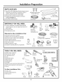
PARTS SUPPLIED:
[] Two #8-18 x 5/8"Phillips special head screws, to secure
dishwasher to underside of countertop or sides of
cabinets. (Tapedto top side of dishwasher.)
[] Side and top trim pieces (on some models)
[] Template with mounting hardware (not shown)
for Model ZBD6890Only
[] Drain Hose and Hose Clamp
MATERIALS
#8 Phillips Special Head
Screws 5/8" Long
Trim Pieces
(on some models)
[]
[]
[]
[]
[]
[]
For New
Installations
90° Elbow,
Ferrule and
Compression Nut
Hand
Shut-Off
Valve
Air gap for drain hose, if required
Waste tee for house plumbing, if applicable
Electrical cable or power cord, if applicable
Screw type hose clamps
Strain relief for electrical connection
Hand shut-off valve
Thread
Seal Tape
Electrical Cable
Hot Water line
(or Power Cord, if applicable@
Waste Tee
Air Gap
Screw Type
Hose Clamps
TOOLS YOU WILL NEED:
Coupler
Strain Relief
Level
[] Phillips head screwdriver
[] 5/16"and 1/4" nutdriver
1/4"
and 5/16"
Nutdriver
Ph
Head
Screwdriver
[] 6"Adjustable wrench
[] Level
Carpenters square
Measuring tape
Safety glasses
Flashlight
Bucket to catch water when flushing the line
15/16"socket (optional for skid removal)
Gloves
For New Installations
Wire Nuts (3)
Only:
[] Water line 3/8" rain. copper
[] Couplerfor extending drain line, if applicable
[]
[]
[]
[]
[]
[]
[]
HoseClamp
YOU WILL NEED:
[] Ferrule, compression nut and 90° Elbow (3/8" NPT
external thread on one end, opposite end sized to fit
water supply)
[] Thread seal tape
[] UL Listed wire nuts (3)
Materials
_
Drain Hose
Carpenters
Square
6''AdJ_t_ta
n
ble
...........
I dddihhhhhhhhl
_115/16" Socket
Tubing Cutter
Measuring Tape
Flashlight
Only:
[] Tubing cutter
[] Drill and appropriate bits
[] Hole saw set
Gloves
Bucket
3
t
Installation
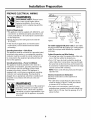
ADVANCE
PLANNING
DISHWASHER
• These dishwashers are designed for versatility,
adaptable to virtually any installation.
• All models have a full length door without the
traditional access panel.
• These dishwashers may be installed beneath
countertops of stone or other materials that will not
accept screws. No trim kit required.
PREPARE DISHWASHER
Preparation
ZBD0710
ZBD6880
ZBD6800
ZBD6800
ZBD6890
ZBD0700
MODELS
SS, Stainless Steel
SS, Stainless Steel
BB, Black
WW, White
Requires a 3/4" custom panel and handle
Requires a 3/4" custom panel and handle
ENCLOSURE
,WARNING
To reduce the risk of electric shock, fire,
or injury to persons, the installer must
ensure that the dishwasher is completely
enclosed at the time of installation.
ThisWall Area
34-1/2"Min,
Undersideof
Countertop
to Floor
Pipesor wires
Square
and
Plumb
Figure B
Countertop
Min_
FloorMUST
beEvenwith
RoomFloor
*Dishwasher models ZBD6890
and ZBDO700require a 3/4"
thick custom panel and will be
24-3/4" deep.
• The rough cabinet opening must be at least 24" deep,
24" wide and approximately 34-1/2" high from floor to
underside of the countertop.
• Plumbing and electrical service must enter the shaded
area.
• The dishwasher must be installed so that drain hose is
no more than 10 feet in length for proper drainage.
T"
34"
Adjustable
to 35"
Dishwasher
Opening2"Minimum
FigureA
CLEARANCES:
When installed
into a corner, allow 2" min.
clearance between dishwasher
and adjacent cabinet, wall or
other appliances. Allow 28-3/8"
min. clearance from the front of
the dishwasher for door
opening (Figure B).
Installation
Preparation
DRAIN REQUIREMENTS
Method 1--Air Gap with Waste Tee or Disposer
An air gap must be used when required by local codes and
ordinances. The air gap must be installed according to
manufacturers instructions.
• Follow local codes and ordinances.
• Do not exceed 10 feet distance to drain.
• Do not connect drain lines from other devices to the
dishwasher drain hose.
__;_
re
NOTE: An air gap must be used, if waste tee or disposer
connection is less than 18" above floor to prevent
siphoning,
DETERMINE
DRAIN METHOD
The type of drain installation depends on the following
question.
[] Do local codes or ordinances require an air gap?
[] Is waste tee less than 18" above floor?
Figure C
Method 2--"High
Disposer
If the answer to either question is YES, Method 1 MUST
be used.
• If the answers are NO, either method may be used.
CABINET
Drain Loop" with Waste Tee or
_.___
PREPARATION
32 _
• Drill a 1-1/2" dia, hole in the cabinet wall within the
shaded areas shown in Figure Afor the drain hose
connection. The hole should be smooth with no
i
sharp edges,
IMPORTANT-when
connecting drain line to disposer,
check to be sure that drain plug has
been removed. DISHWASHER WILL
NOT DRAIN IF PLUG IS LEFT IN PLACE,
FigureD
Remove
Hopper
Plug
5
Min. -L_
Installation
Preparation
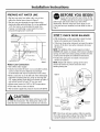
PREPARE ELECTRICAL WIRING
FOR PERSONAL SAFETY:Remove house
fuse or open circuit breaker before
beginning installation. Do not use an
extension cord or adapter plug with this
appliance.
WARNING
1-1/2" Dia.
Hole(Max.)
Electrical Requirements
• This appliance must be supplied with 120V,60 Hz., and
connected to an individual properly grounded branch
circuit, protected by a 15 or 20 ampere circuit breaker
or time delav fuse.
from
Cabinet
Receptacle
Location
Area
• Wiring must be 2-wire with ground and rated for
75°C (176°F).
FigureE
White
• If the electrical supplv does not meetthe above
requirements, call a licensed electrician before
proceeding.
For models equipped with power cord: Do not modify
the plug provided with the appliance; if it will not fit the
outlet, have a proper outlet installed by a qualified
technician.
Grounding Instructions--Cable Direct
This appliance must be connected to a grounded metal,
permanent wiring system, or an equipment grounding
conductor must be run with the circuit conductors and
Cabinet Preparation and Wire Routing
• The wiring may enter the opening from either side,
rear orthe floor within the shaded area.
be connected to the equipment grounding terminal or
lead on the appliance.
• Cut a 1-1/2" max. dia. hole to admit the electrical
cable. Cable direct connections may pass through
the same hole asthe drain hose and hot water line,
if convenient. If cabinet wall is metal, the hole edge
must be covered with a bushing.
Grounding Instructions--Power Cord Models
This appliance must be grounded. In the event of a
malfunction or breakdown, grounding will reduce the
risk of electric shock by providing a path of least
resistance for electric current. This appliance is
equipped with a cord having an equipment grounding
conductor and a grounding plug. The plug must be
plugged into an appropriate outlet that is installed and
grounded in accordance with all local codes and
ordinances.
NOTE: Power cords with plug must pass through a
separate hole.
Electrical Connection to Dishwasher
Electrical connection is on the right front of
dishwasher.
• For cable direct connections the cable must be
routed as shown in Figure E. Cable must extend
a minimum of 24" from the rear wall.
WARNING
The improper connection of the equipment
grounding conductor can result in a risk
of electric shock, Check with a qualified
electrician or service representative if you
are in doubt that the appliance is properly
grounded,
• For power cord connections, install a 3-prong
grounding type receptacle in the sink cabinet rear
wall, 6" rain. or 18" max. from the opening, 6" to 18"
above the floor.
6
Installation
Instructions
BEFORE YOU BEGIN
PREPARE HOT WATER LINE
• The line may enter from either side, rear or floor
within the shaded area shown in Figure E
• The line may pass through the same hole as the
electrical cable and drain hose. Or, cut an additional
1-1/2" dia. hole to accommodate the water line.
If power cord with plug is used, water line must
not pass through power cord hole.
Locate and set aside (for use in Step 12) the
2 Phillips special head screws wrapped with
yellow tape and stuck to the top or side of the
dishwasher. Remove drain hose from upper rack, if
it has not been pre-installed, and set aside for use in
Step 7.
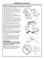
[STEP 11CHECK DOOR BALANCE
j
/
/
I
I
/4-I
I
fl
Shut-off
Valve
I,,
,,,,
!,:::_
F[om
Z_//
Cab,net
i
- -I,
19" FromWall
/[/_--2"
From Floor
• If the door drops when released, increase the spring
tension. If the door rises when released, decrease
the tension.
NOTE: The addition of the custom panel on model
ZBD6890 will require exchange of the factory installed
springs. Use the heavy-duty springs provided. See the
custom panel template for additional instructions.
I:
Cabinet Face-_
Water
\\
]
|
/4- - .....
Hoti:::::
\
l
1-1/2 Dia.
Hole
• With dishwasher on the wood skid, check the door
balance by opening and closing the door.
\
I
]'\
\
• Position the spring for increased or decreased
tension as required.
X-Figure
F
Line Connection
• Turn off the water supply.
• Install a hand shut-off valve in an accessible location,
such as under the sink. (Optional, but strongly
recommended and may be required by local codes.)
• Water connection is on the left side of the dishwasher.
Install the hot water inlet line, using no less than 3/8"
O.D. copper tubing. Route the line as shown in Figure F
and extend forward at least 19"from rear wall.
NOTE: Adjust both balance springs to the same
amount of tension to prevent excessive door
twisting during use.
FigureG
• Adjust water heater for 120°F to 150°F temperature.
• Flush water line to clean out debris.
• The hot water supply line pressure must be 20-120 PSI.
CAUTION
Pulle
Do not remove wood base until you are ready
to install the dishwasher. The dishwasher will tip over
when the door is opened if the wood base is removed.
Decrease
Tension
Shoulder
Correct Spring
Cable Routing
Tension
TIP: If door does not open easily or falls too quickly,
checkthe spring cable routing. Checkthatthe
cable
is properly aligned on the pulley (as shown).
Installation
Instructions
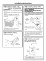
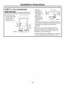
[STEP41INSTALL
ISTEP 21REMOVE WOOD BASE,
INSTALL LEVELING
LEGS
POWER CORD
UsePower CordKit WX09XT0910
availablefor purchasefroman
authorizedGEAppliancesdealer.
IM PORTANT- Do notkickoff woodbase!Damage
will occur.
Skipthisstepif dishwasherwill bedirectwired or hasa
factoryinstalledpowercord.
• Move the dishwasher closeto the installationlocation and layit
on its back.
The power cord and connections mustcomplywith the National
Electrical Code,Section 422and/or local codes and ordinances.
• Removethe four leveling legs on the undersideof the
wood basewith an adjustablewrench or 15/16"socket.
• Discard base.
• Maximumpower cord length is 4 feet beyondthe back of the
dishwasher.
A
B
Remove
Insert Power
Junction Box CordWires
Cover
Strain Relief
Whit
_
andTighten
Gr°u L
C CheckThat White, Black and_
Green Dishwasher Wires Are Threaded
D
Thru Small Hole in Bracket
Use UL Listed
Figure H
• Screw levelinglegs back into the dishwasherframe,
approximately1/4"from frame as shown.
Figure K
_
///
Wire Nuts _/
• Connectincoming power cord white (or ribbed)to dishwasher
white, black (or smooth)to black and groundto dishwasher
green wire. Use ULlisted wire nuts of appropriatesize.
ISTEP 31REMOVE TOEKICK
• Removethe two toekick screws.
• Replacejunction box cover.Be surewires are not pinched
under the cover.
[STEP 51 INSTALL 90 ° ELBOW
• Wrap 90° elbow with thread sealtape.
• Installa 90o elbow ontothe water valve.
Frontof Dishwasher
Remove2
Toekick Screws
FigureJ
_
Water Valve
Bracket
Elbow
90° _
II Hose
FigureL
8
Thread
Seal Tape
• Donot overtighten90° elbow,water valve bracket could bend
or water valve fitting could break.
• Positionthe end of the elbow to face the rear of the dishwasher.
Installation
Instructions
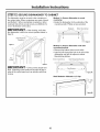
ISTEP61POSITION WATER LINE
ISTEP 81 SLIDE DISHWASHER
PARTIALLY INTO CABINET
AND HOUSING WIRING
DO NOT PUSH AGAINST FRONT PANEL WITH KNEES.
DAMAGE WILL OCCUR.
• Position water supply line and house wiring on the
floor of the opening to avoid interference with base
of dishwasher and components under dishwasher.
"
"
• Slide dishwasher into the opening a few inches
at a time.
4"
_,,5___
__
...._:__
House\\
\
W_tner Wiring _
FigureM
_er
\
Do Not PushAgainst
Front Door Panel With
Knee. Damage to The
Door Panel Will Occur.
ISTEP 71INSTALL DRAIN HOSE,
GUIDE THROUGH
CABINET
• Remove tape and wire tie holding the clamp to the
drain hose. Be careful not to damage the drain hose.
by Grasping Both
Sides With Hands
FigureP
• As you proceed, pull the drain hose through the
opening under the sink. Stop pushing when the
dishwasher is a few inches forward of adjacent
cabinetry.
• Make sure drain hose is not kinked under the
dishwasher and there is no interference with the
• Stand the dishwasher upright.
• Slip the supplied
hose clamp over
the large end of
the hose. Do not
water line and wiring or any other component.
tighten.
ISTEP 91 INSTALL TRIM PIECES
Skip this step if trim is not supplied with the
dishwasher.
Figure N
• Locate trim strips inside dishwasher,
• Press trim onto the tub flange on each side, Start
with the top edge, pressing on as you move towards
the bottom,
• Push hose over the drain outlet on the back side of
the dishwasher. See illustration. Push the hose over
the outlet and against the shoulder stop,
• Press the two top trim pieces on each side of
the latch,
• Tighten the hose clamp with a 1/4" nut driver.
Insulation
Blanket
• Open and close the door to check that trim does not
bind and does not interfere with door latch.
Water
Trim Strip
Figure0
House
Wiring
Power Cord
(If Used)
• Position the dishwasher in front of the opening.
Insert drain hose into the cabinet side. If power cord
is used, guide the end through a separate hole,
Strip
Figure Q
9
Installation
ISTEP 101 POSITION
DISHWASHER
Instructions
UNDER COUNTERTOP
• Push the dishwasher into the cabinet.
• Push at the sides with your hands. Do not use your
knee against the door since door damage will occur.
• Check that the tub insulation blanket does not get
"bunched-up" or interfere with the springs as you
slide it into the cabinet.
• Center the dishwasher in the opening.
Do Not PushAgainst
• Check that the edges of the dishwasher door are
behind the cabinet frame and aligned with the front
face of the cabinet as shown.
Sides With Hands
Front Door Panel With
Knee. Damage to The
Door PanelWill Occur.
• Carefully open and close the door to ensure that the
door panel does not catch or rub on the cabinet frame.
er
Figure
R
• If the door catches or rubs on the frame, reposition
and/or level the unit (see Step 11) until the door moves
freely and does not contact the cabinet frame.
The controls are designed to be hidden by your
countertop. Align the dishwasher as shown in Figure T.
NOTE: If the drain hose gets trapped between the wall
and the back side of the dishwasher, it can prevent the
dishwasher from sliding all the way back into the
cabinet opening, and thus preventing a flush fit with
the kitchen cabinet panels.
Door
Fitsand
Swings
Back
Behind
Cabinet\
Frame
TIP: For best appearance installations of custom panel
models, it may be necessary to cut off the back panel
of the tub insulation blanket so that the dishwasher
door panel can be aligned flush with the kitchen
cabinet panels.
Correct
Alignment
The leveling legs can be used to increase or decrease
the amount of gap between the controls and the
countertop affecting the visibility of the controls.
Leave a 1/2" minimum gap between the underside
of the countertop and the top of the dishwasher
door (see Figure V).
IMPORTANT-
,''
i
Top View
,,,,,'''''
Controls Hidden
by Countertop
Leave a 1/2" minimum
gap between the controls and the underside of the
countertop to prevent condensation and damage to the
control panel from screwheads.
FigureS
NOTE: If this dishwasher is replacing an existing
dishwasher, the old countertop bracket screw holes
may not be in the correct position to accept a top
control model. New holes may be required.
Mo .,oml
Figure
T
Countertop
2 mm.
FigureV
Figure U
10
Installation
Instructions
ISTEP 111 LEVEL DISHWASHER
IMPORTANT-
• Level the
dishwasher by
adjusting the
four leveling legs
individually.
• Make sure 1/2"
minimum gap is
maintained (see
Figure V).
Dishwasher must be level
for proper dish rack operation and wash performance.
and rack track inside
• Place level on door
the tub as shown to
f
/
check that the
//(fi
_//
dishwasher is level.
/////
////
J__o
Access Hole
Turn Legsl
_
/
FigureX
If adjustment to the right rear leveling leg is required,
gain access by loosening junction box bracket screw
(through the access hole) and rotate bracket
clockwise,
TIP: Pull lower rack out, about halfway, Check to
be sure the rack does not roll forward or back into
dishwasher. If the rack rolls in either direction, the
dishwasher must be leveled again,
Side
• If the door hits the tub, the dishwasher is not installed
correctly, Adjust leveling legs to align door to tub,
11
Installation
ISTEP 121 SECURE DISHWASHER
Instructions
TO CABINET
Method 1--Secure dishwasher to wood
countertop
• Fasten the dishwasher to the underside of the
countertop with 2 Phillips screws provided,
The dishwasher must be secured to the countertop or
the cabinet sides. When countertops are made of wood,
use Method 1. When countertops are granite or other
materials that will not accept screws, use Method 2 to
secure dishwasher atthe sides.
Brackets
IMPORTANT-After
leveling, verify that
the dishwasher is still in the correct position shown in
Step 10.
Wood Countertop
/
j"
Side Mounting
Brackets
t_I
Figure Y
Figure Z
Method 2--Secure dishwasher with side
mounting brackets
• Remove plug buttons (one on each side).
Tub
• Install screw through the hole in the side of the
dishwasher and into the adjacent cabinet.
Reinstall plug buttons.
Countertop
Mounting
Brackets
Stone Countertop
Side Mounting Brackets
J_
Figure Y
IMPORTANT-
Drive
screws
straight
and
flush. Protruding screw heads will scratch the top or
sides of the control panel and can interfere with door
closing.
FigureAA
Both Methods--Maintain
12
1/2" Gap
Installation
Instructions
ISTEP 131CONNECT WATER SUPPLY
Connect water supply line to 90° elbow.
• Slide compression nut, then ferrule over end of
water line.
• Insert water line into 90° elbow.
Line
• Slide ferrule against elbow and secure with
compression nut.
IMPORTANT-
Check to be sure that door
spring does not rub or contact the fill hose or water supply
line. Test by opening and closing the door. Re-route the
lines if a rubbing noise or interference occurs.
ISTEP 141 CONNECT
Figure CC
DoorSpring
90° Elbow
DRAIN LINE INSTALLATION
DRAIN LINE
FOLLOW ALL LOCAL CODES AND ORDINANCES,
• Connect drain line to air gap, waste tee or disposer
using either previously determined method.
The drain hose molded end will fit 5/8" or 1"diameter
connections on the air gap, waste tee or disposer. Cut
on the marked line as required for your installation.
Method
__
1--Air
gap with waste tee or disposer
re
__
re
Cutting Line
FigureDD
,/
/.
IMPORTANT:Do not cut corrugated
portion of hose
Waste Tee Installation
Disposer Installation
FigureFF
Method 2--"High
disposer
_ _
drain loop" with waste tee or
Fasten to underside
Fasten to underside
of countertop,
of countertop,
i_
• If a longer drain hose is required, add up to 42" of
length for a total of 10 ft. to the factory installed hose.
Use 5/8" or 7/8" inside diameter hose and a coupler to
connect the two hose ends. Secure the connection
with hose clamps.
32"
Figur_
Coupler
Hose Clamp
Hose Clamp
Waste Tee Installation
• Secure the drain hose to the air gap, waste tee or
disposer with clamps.
Disposer Installation
Figure GG
NOTE: TOTAL DRAIN HOSE LENGTH MUST NOT EXCEED
10 FEET FOR PROPER DRAIN OPERATION.
IMPORTANT-when
i--_/__
connecting drain line to disposer,
_1
check to be sure that drain plug has ,._
been removed. DISHWASHER WILL
NOT DRAIN IF PLUG IS LEFT IN PLACE.
Remove
Hopper
Plug
TIP: Avoid unnecessary service call charges. Always
be sure disposer drain plug has been removed before
attaching dishwasher drain hose to the disposer.
13
Installation
Instructions
ISTEP 151CONNECT POWER SUPPLY
ISTEP 161PRE-TEST
Skip this step if equipped with power cord,
Go to step 16.
Verify that power is turned off at the source,
Review this list after installing your dishwasher to
avoid charges for a service call that is not covered
by your warranty,
• Remove junction box cover "A".
[] Check to be sure power is OFF.
• Secure house wiring to the back of the junction box
with a strain relief "B".
[] Open door and remove all foam and paper
packaging.
• Locate the three dishwasher wires, (white, black
and green) with stripped ends. Insert dishwasher
wires through the small hole in the junction box "C".
Use wire nuts to connect incoming ground to green,
white to white and black to black "D".
[] Locate the Owner's Manual in the literature
package.
[] Read the Owner's Manual for operating instructions.
[] Check door opening and closing. If door does not
open and close freely or tends to fall, check spring
cable routing and spring adjustments. See Step 1.
• Replace junction box cover "E". Check to be sure
that wires are not pinched under the cover.
A
Remove
Junction Box
Cover
_
[] Checkto be sure that wiring is secure under the
dishwasher, not pinched or in contact with door
springs or other components. See Steps 8 and 10.
B
Insert Power
CordWres Thru
Strain Relief
andTighten
CHECK LIST
i
[] Check door alignment with tub. If door hits tub,
level dishwasher. See Step 11.
White
[] Pull lower rack out, about halfway. Check to be
sure it does not roll back or forward on the door.
C CheckThat Wl_ , B_ik-lnd
_
Gr°und___
If the rack moves, adjust leveling legs. See Step 11.
i Black
[] Check door alignmentwith cabinet. If door hits
cabinet, reposition or relevel dishwasher. See
Steps 10,11 and 12.
GreenDishwasherWires Are Threaded
Thru Small Holein Bracket
D
Use UL Listed
Wire Nuts
E ReplaceJunction BoxCover
[] Check that door spring does not contact water line,
fill hose, wiring or other components. See Step 13.
FigureHH
[] Verify water supply and drain lines are not kinked
or in contact with other components. Contact with
motor or dishwasher frame could cause noise.
See Steps 6 and 8.
If house wiring is not 2-wire with ground,
a ground must be provided by the
installer. When house wiring is aluminum,
be sure to use UL Listed anti-oxidant
compound and aluminum-to-copper
connectors.
WARNING
[] Turn on the sink hot water faucet and verify water
temperature. Incoming water temperature must
be between 120°F and 150°F.A minimum of 120°F
temperature is required for best wash performance.
See "Prepare Hot Water Line," page 7.
[] Add 2 quarts of water to the bottom of the
dishwasher to lubricate the pump seal.
[] Turn on water supply. Check for leaks. lqghten
connections if needed.
[] Remove protective film if present from the control
panel and door.
14
Installation
Instructions/Custom
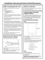
ISTEP 171 DISHWASHER
Panel Dimensions
[STEP191LITERATURE
WET TEST
[] Turnon power supply (or plug power cord into outlet,if
equipped).
• Be sure to leavecompleteliterature packageand installation
instructionswith the consumer.
[] Start the unitto checkfor leaks.
- PushRINSEONLYpad.
- PushSTART/RESET
pad one time.
- Closedoor.
CUSTOM
ZBD6890,
[] Checkto be sure that water enters the dishwasher.If water
PANEL FOR MODEL
ZBDO700
Thesedishwashers require a field installed 3/4"thick custom
panel and custom handle.An installationtemplateis packed
with these models and may be obtainedin advance.Order
Pub.No. 31-30569-1.
Completepanel installationinstructions
are includedon the template.
does not enter the dishwasher,check to be sure that water
and power are turned on.
[] Checkfor leaks underthe dishwasher.If a leak isfound, turn
power supply off,then tighten connections.Restorepower
after leak is corrected.
CUSTOM
[] Checkfor leaks aroundthe door.A leakaround the door
could be causedby door rubbing or hitting against adjacent
cabinetry.Repositionthe dishwasherif necessary.See Step12.
PANEL SEE REQUIREMENTS
HEIGHT
Panelheightmustbe between30-1/16"and30-1/4".
[] The dishwasherwill drain and turn off about 5 minutesafter it
was started.Checkdrain lines.If leaks are found,turn power
off atthe breakerand correct plumbingas necessary.Restore
power after corrections are made.See Step 15.
30-1/16" Min.
30-1/4" Max.
[] Open dishwasherdoor and makesure most of the water has
drained.If not, check that disposer plug has been removed
and/or air gap is not plugged.See Step14.Also check drain
line for kinking.
[] Runthe dishwasherthrough another "Rinse0nly" cycle.
Checkfor leaks and correct if required.
_23-3/4"_
• If the panel heightis morethan 30-1/4"it will preventthe door
from swinging open.
ISTEP 181REPLACE TOEKICK
• If the panel heightis lessthan 30-1/16"it will not cover the
dishwasherdoor frame.
• Placetoekick against the legs of the dishwasher.
t
• Thetop of the custom panel must beflush with the top of the
door.The 1/2"minimumgap betweenthe top of the door and
the bottomof the countertopmust be maintained.
Countertop
Figure II
Z2"
mio
• Align the toekick with the bottomedge and make sureit is
against the floor.
• Insert and tighten the two toekick attachmentscrews. The
toekick shouldstay in contact with the floor.
WIDTH
TIP: Make suretoekick is againstfloor to minimizenoise.
Panelwidth mustbe23-3/4".
• If the panelwidth is less than 23-3/4"it will not cover the
dishwasherframe.
IMPORTANT:
Toensureoptimumdoorbalanceperformance,
the custompanelmustnotweigh morethan 14Ibs.
15
NOTE:While performing installations described in this book,
safety glasses or goggles should be worn.
I_." Motwg'r.m °'_loon! ._t._-vic_"
itt yo_tr _tre., .ill
l. 800.444. 1845.
NOTE: Pro(hl(:t
iml)rov¢_m(nl
is a cot_tinuing
(:ride ax'or _t
(;(_n(_l-_d El(_(tric.
Tller(_i_r(,
malel-ials,
_q)l)(_n-an(¢_
Sl)(_(i_](_lions
_t'(_ sul)je(t
to (ll_lng(' wilhoul
noli(¢!.
and
Monogram:
Pub.No. 31-30586
]
PartNo. 206C1559P126
J
GE Consumer & Industrial
LouisviIJe, KY40225
11_04JR
@2004 GE Company


![[U4.92.11] Procédure ENGENDRE_TEST](http://vs1.manualzilla.com/store/data/006367543_1-7a8bc9bbf5b71ba531fd386dd19da1a3-150x150.png)