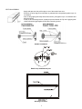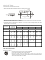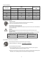
1
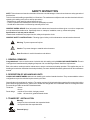
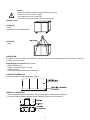
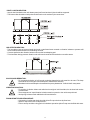
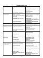
SERVICE MANAUL
DOUBLE SKIN AIR HANDLING UNITS
KW & KWH SERIES
PL-OM-KWS-00-1M-E
INDEX
Contents
Page
Safety instructions .................................................................................................................................... 2
General remarks ....................................................................................................................................... 2
Description of air handling units ................................................................................................................ 2
Transport - Installation .............................................................................................................................. 2
Assembly, Start Up & Maintenance ......................................................................................................... 6
Casing ...................................................................................................................................................... 8
Fan section ............................................................................................................................................... 8
Air inlet/Control section .......................................................................................................................... 13
Dampers ................................................................................................................................................. 13
Filter section ........................................................................................................................................... 13
Pre-filter & bag filter ................................................................................................................................ 13
Heater section ........................................................................................................................................ 14
Hot water ................................................................................................................................................ 14
Electric heater ........................................................................................................................................ 15
Cooling section ....................................................................................................................................... 15
Chilled Water .......................................................................................................................................... 15
Direct Expansion .................................................................................................................................... 16
Heat recovery system ............................................................................................................................. 16
Humidifier section ................................................................................................................................... 17
Air washer .............................................................................................................................................. 17
Steam humidifier ..................................................................................................................................... 17
Sound attenuator section ........................................................................................................................ 17
Multizone section .................................................................................................................................... 17
Maintenance instructions
.................................................................................................... 17
Troubleshooting ...................................................................................................................................... 18
Maintenance program ............................................................................................................................. 20
CONTINUING RESEARCH RESULTS IN STEADY IMPROVEMENTS.
THEREFORE, THESE SPECIFICATIONS ARE SUBJECT TO CHANGE WITHOUT NOTICE.
1
SAFETY INSTRUCTION
NOTE: This maintenance instruction describes all functions and advantages of the units and assure a safety operation of
theclient/user.
Technical use and handling responsibility is of client/user. The maintenance staff/personnel must be trained technicians in
operating air handling units (refer to start-up procedure).
- Maintenance, repair works by trained personnel only.
- Function operation and maintenance to be done periodically as stated.
- Should above instructions not followed up, warranty will be void.
OBSERVE USER’S ADVICE: User information of this maintenance instruction and those given on units or components
must be observed and adhered to. Specifically those on transport, installation, start up, restart and upkeep.
Specification of unit may not be altered!
Unauthorized modification may impair function, safety and operation of unit.
OBSERVE SAFETY INSTRUCTIONS: Following signs of safety on this maintenance manual must be observerd.
Warning: To prevent personnel injuries.
Caution: To prevent damage to material and environment.
Note: Reminder for useful informations and advises .
1. GENERAL REMARKS
Congratulations! You are now the owner of a double skin air handling unit by CLASSIC AIR CONDITIONERS. This unit
is designed and manufactured by adapting all aspects of air conditioning and static load/force requirements.
Each unit needs a certain preventive maintenance to ensure continuous and safety operation. This applies that your air
handling unit need to be checked and serviced periodically. For exact detailed informations, please refer to this maintenance
manual.
2. DESCRIPTION OF AIR HANDLING UNITS
CLASSIC AIR CONDITIONERS double skin air handling unit consist of standard sections. They are assembled to various
configurations as per the technical requirements by the client.
Generally the units are shipped in sections. The casing consists of rigid galvanized sheet steel profile construction joint by
glass reinforced polyamid corners. Panels are of double skin design with non-combustible rockwool or fiberglass insulation according to DIN 4102 and NFPA 90A standards.
Thickness:
- 30 mm
- 50 mm
Panel design: - outside 0.75 mm thick, dark gray coated
- inside 1.25 mm thick, galvanized steel sheets
3. TRANSPORT - INSTALLATION
Warning:
- keep area clear underneath the suspended loads
- don’t pass below the suspended load
Personal injury !
2
Caution !
- protect air handling unit against impact shocks or being drop
- don’t let unit rest on corners or edges
- don’t support the unit on corners only
- don’t lift the unit on pipe stubout, other than lifting points
Damage of unit !
LIFTING BY:
- forklift
- stacker trucks with squared timber
LIFTING BY:
- crane
FOUNDATION:
Foundation for the air handling unit shall be 50 - 100 mm, wider than the unit base dimension on each side. Surface of
foundation shall be levelled.
Height/Design of Foundation shall consider:
- Shipping weight of unit
- Height of condensate syphon or p-trap
- Vibration isolation
- Solid sound conduction/transmission absorption
CONCRETE FOUNDATION:
Concrete foundation should withstand the vibration.
PEDESTAL FOUNDATION:
- With the pedestal foundation construction, the unit bottom panel profile should be supported.
- The intermediate foundation pedestals should match the unit section joint connections.
3
POINT LOAD FOUNDATION:
- At point load foundations the units bottom panel profile and sectional joints should be supported.
- The intermediate foundation load points should match to unit sectional joint connections.
ISOLATED FOUNDATION:
- The foundation frame of structural steel reinforced or steel base frame mounted on vibration isolators to prevent solid
sound conduction/transmission to the building structure.
- Concrete pad below the vibration isolators serve as the housekeeping pad.
- This foundation design prevents vibration and solid sound conduction/transmission to sensitive areas.
SOLID SOUND REDUCTION:
- For prevention/reduction of solid sound conduction/transmission soft material to be used. The deep
soft material do have higher sound adsorption characteristic efficiency.
- Mineralwool with sound absorption characteristic frequency between 20 - 30 Hz is ideal in many cases.
VIBRATION ISOLATION:
- For selection of vibration isolator and aside from the weight of units/ foundation, the air thrust load must be
considered also.
- The arrangement of equal vibration isolations must be symetric to the unit thrust point load.
- Steel spring isolators needs additional solid sound silencer.
DRAIN-HEIGHT/FOUNDATION-HEIGHT:
- Connection of condensate drain pipe with siphon/P-trap to be done by client/user.
- Siphon/P-trap must not be under pressure.
- Prior to start-up and after a long period of shutdown-operation siphon/P-trap must be filled with water.
4
DESIGN OF SIPHON/P-TRAP
Draw Thru
Blow Thru
SERVICE ACCESS
5
4. ASSEMBLY, START UP & MAINTENANCE
4.0 UNIT SECTION
INSTALLATION
If you use a pedestal base, please consider cross member beam in every section joints (Changes to be agreed by the
manufacturer). For joining of sections the supplied Fastener Kit compose of screws, washers and sealtape to be used.
SECTION ASSEMBLY
KW series
KWH series
Fastener Kit
Unit type – KW/KWH
Quantity per joint, each
KW/KWH01 - 13
KW/KWH 16 - 50
KW/KWH 55 -130
1 - Hexagonal screw M 8 x 80mm
4
6
-
2 - Spring washer M 8
4
6
-
3 - Cap nut, hexagonal M 8
4
6
-
4 - Self-adhesive seal tape
-
-
-
5 - Assembly clamp
-
2
4
6 - Hexagonal screw M 6 x 20mm
-
4
8
1 - Hexagonal screw M 8 x 120mm
4
6
8
2 - Spring washer M 8
4
6
8
3 - Cap nut, hexagonal M 8
4
6
8
4 - Self-adhesive seal tape
-
-
-
5 - Assembly clamp
-
2
4
6 - Hexagonal screw M 6 x 20mm
-
4
8
Panel Thickness, 30mm
Panel Thickness, 50mm
6
SECTION ASSEMBLY
- Apply seal tape near the profile edge on one of the section face area.
- Sections are to be aligned on foundation or pedestal and to be pushed together up to 10
cm distance.
- Now, fix the gripping belt/clamp around the section, pull together up to 1 cm distance and
align the section.
- Finally fix all connecting screws, quantity as per the fastener kit. By use of gripping belt/
clamp pull section tight together and fix the connecting screws.
Outdoor Installation
Detail of top weatherhood joint
Stacking of sections
7
CASING:
START-UP
Prior to start-up all maintenance panels are to be closed. Check all maintenance panels and locks for proper closure.
Specifically for all maintenance on positive pressure side of fan.
ALIGNMENT OF PANELS/DOORS
Prior to final alignment the unit installation position to be checked and levelled.
INSPECTION
Damages of outside unit panels/casing to be cleaned from dirt, then treated with primer and repaint with touch up paint.
For galvanized casing parts the damaged portion to be rust free (metallic bright) and repaint with cold galvanizer.
4.1 FAN SECTION
ASSEMBLY
Motor and fan are built together as one functional component on a commmon base frame, internally isolated to the unit
casing. For power supply the local regulations to be followed. Main voltage must comply with data given at motor nameplate. Thermal over-current safety cut-outs are to be provided by client, the motor is not provided with protective device
like; thermistor protectors in the motor winding. If thermal relay are used, they are to be set in accordance to values shown
on motor nameplate.
For maintenance and emergency function it is mandatory to shutdown the motor/unit.
START-UP
After completion of all mechanical and electric power connection, the correct rotation of fan motor to be checked. Change
the rotation by interchanging the 2-phases of power supply.
The maximum elongation of V-belts occurs in the first operating hour. Therefore, it is highly recommended that after 30
minutes of full load operation the V-belt tension should be checked.
MAINTENANCE
Warning!
Prior to opening of any access/maintenance panel, unit to be shutdown.
Inspection of rotation can be done by opening the fan section access panel or through the sight glass.
Caution!
- motor could be overloaded.
- hold the access panel during inspection.
Inspection of rotation when door is closed only on unit sizes KW/KWH 32-130.
Warning!
Inspection inside the fan section cause high risk of accident due to V-belt and fan.
During inspection of fan motor following can be observed:
- flapping of V-belt
- wobbling of fan impeller
- bearing noise
- unbalance fan impeller
MAINTENANCE/REPAIR WORK FOR FAN MOTOR
Warning!
If no lockable repair switch is provided, switch-off circuit breaker or remove fuses at switchboard.
Both provisions to be labeled at unit.
MOTOR
Regarding bearings maintenance refer to manufacturer instructions. Lubrication instructions normally are
given on motor nameplate.
8
FAN
Bearings
Generally only proven and low noise accuracy ball bearings are fitted with theoretical life-time of minimum 200,000 operating
hours. The V-belt and drive pulleys to be calculated accordingly. Permissible bearing loads not to be exceeded.
V-belt tension
KW/KWH01 - KW/KWH02 with motor saddle for tension of V-belt.
KW/KWH03 - KW/KWH130 with parallel sliding rail for tension of V-belt.
For tension of V-belt, safety screw of spindle at sliding rail (see figure above) to be loosened and spindle turned clockwise
until recommended V-belt tension is reached.
Caution!
Prior to start-up all screws/bolts to be checked and tighten.
Damage of material.
HIGH EFFICIENCY NARROW V-BELTS
Possible elongation of new V-belt drives is about 80 % in the first 15 hours of operation. Therefore, in the beginning
deflection ‘f’ shall only be approximate 70 % of the calculated value. After 50 hours of operation recheck V-belts and
retension them, if necessary.
Attention!
1) When mounting V-belt in shorter shafts distance, do not force belts into grooves by screw drives or similar object.
2) In case of multiple V-belt drives replace always all belts at the same time. Care should be taken to ensure that belts
have the same length (use matched sets only).
3) Pulleys shall be properly align.
CHECK OF PULLEYS ALIGNMENT
4) When replacing V-belts the same belt type/profile should be used again.
EXPLOSION HAZARD
5) Warning!
For explosion hazardous plant/application only electrically conductive V-belts may be used.
Explosion hazard!
6) Regular checking of belt tension and retensioning in intervals of about 800 operating hours ensure longer life of belts.
Abnormal heating, excessive flapping of the belt between pulleys and noise are indication of insufficient belt tension.
Insufficient tension lead to slip and premature failure as well.
9
CHECK OF V-BELT TENSION
Correct belt tension can be determined as follows:
1. Measure belt length (upper length between pulleys) or calculate it by the formula.
2. According to table below determine power, ‘P’ by which the belt will be loaded as per the belt profile, pitch diameter,
RPM of the small pulley as well as ratio of transmission.
3. At standstill, pretension of belt shall have a deflection ‘f’ of 1 mm per 100 mm belt length between pulleys when
defelction power ‘P’ arise at each belt.
Belt profile
Power ‘P’ in kg. to deflect V-belt RPM of small pulley
Pitch pulley
diameter, dw
700
1450
2800
4000
Transmission, i
x SPZ
x SPA
x SPB
x SPC
UP TO
1
3
1
3
1
3
1
3
63
90
1.03
1.35
0.9
1.23
0.81
1.13
0.74
1.04
100
125
1.21
1.57
1.09
1.42
0.97
1.29
0.89
1.19
140
180
1.33
1.71
1.21
1.54
1.08
1.37
0.97
1.25
90
125
1.54
2.11
1.36
1.9
1.18
1.68
1.05
1.51
140
180
1.84
2.4
0.66
2.17
1.45
1.92
1.27
1.71
200
225
2.02
2.55
1.82
2.3
1.57
2
-
-
140
200
2.45
3.28
2.16
2.93
1.8
2.5
1.5
2.13
224
280
2.8
3.6
2.5
3.2
2
2.7
-
-
315
400
3.03
3.8
2.65
3.45
-
-
-
-
224
315
4
5.33
3.45
4.66
-
-
-
-
335
450
4.5
5.9
3.9
5
-
-
-
-
500
630
4.8
6
-
-
-
-
-
x numbers of belts.
V-BELT PULLEY WITH BUSHING
ASSEMBLY OF PULLEY
- The pulleys machined surface must be cleaned and degreased.
- Fit pulley and bushing together and align the fixing holes.
- Grease bolts slightly, screw them slightly into the thread holes of the bushing.
Slide pulley with bushing into the shaft, align it and tighten bolts uniformly (for tightening torque
refer to torque schedule table on next page).
10
TORQUE SCHEDULE
Bolts
Numbers
Size (inch)
Length (inch)
Tightening Torque,
(Nm)
1108
2
1/2
1/2
5.7
1210
2
3/8
5/8
20
1610
2
3/8
5/8
20
2012
2
7/16
7/8
31
2517
2
1/2
1
49
3020
2
5/8
1-1/4
92
3030
2
5/8
1-1/4
92
3535
3
1/2
1-1/2
10
Bushing No.
DISMANTLING OF PULLEY
- Remove the bolts.
- Tighten one of bolt into pulley thread hole until pulley get loose from bushing.
- Now remove pulley/bushing by hand. Don’t use any tools.
ADJUSTABLE PITCH MOTOR PULLEY
If drive is equipped with an adjustable motor pulley, fan rpm and air volume can be varied within the
fan performance range.
Caution!
When adjusting motor pulley do not exceed maximum fan rpm and full load motor current.
Damage of motor!
Manufacturer has already set adjustable pulley to required pitch diameter, according to unit technical data.
Variation of the air volumes can be made according to the following instructions:
Adjustable pitch pulley
Increase pitch diameter
Decrease pitch diameter
Motor
air volume increase
air volume decrease
ADJUSTMENT OF PITCH PULLEY DIAMETER
When adjusting pitch diameter proceed as follows (refer to example):
a) Determine adjustment: Adjustment = max. pitch dia. - new pitch dia.
4 x regulation factor
b) Loosen adjustment bolt (see figure).
c) By closing adjustable pulley find out maximum pitch diameter. After this, open it to get the
calculated RPM. (Adjustment should only be made in 1/4 turn.
d) By doing so, a thread hole in the idle pulley is then matched automatically with the flatening of the
fixed pulley. Turn in adjusting screw into this thread hole and tighten it strongly.
11
Adjustable pulley
Profile
SPZ
SPA
Outside dia.
Outside dia.
Pitch dia.
Regulation factor
84
62...80
1.64
95
73...91
1.64
100
78...96
1.64
108
90...104
1.45
108
76...102
1.64
120
88...114
1.64
129
97...123
1.64
139
109...133
1.54
146
116...140
1.54
156
126...150
1.54
164
134...158
1.54
EXAMPLE OF ADJUSTMENT
Conditions:
Belt profile SPZ, adjustable pulley 100 mm outside diameter,
maximum pitch diameter (refer table above) = 96 mm
regulating factor (refer table above) = 1.64
new determined pitch, Diameter = 83 mm
Requested:
Adjustment (no. of turns)
Solution:
Adjustment = 96 - 83 = 1.98 = 2 turns open
4 x 1.64
12
4.2 AIR INLET/CONTROL SECTION
DAMPERS
INSTALLATION
Electric connection of damper motor to be done in accordance to manufacturer instructions.
ADJUSTING TORQUE, (Nm)
Model No.
1 Damper
2 Dampers
(mixing box)
3 Dampers
(mixing box)
1 Damper
air tight
KW/KWH 01
1.8
2.1
2.2
2.5
2.5
3.3
3.3
4.0
4.0
6.0
6.0
7.5
7.5
10.0
10.0
9.7
10.9
11.9
12.9
14.5
23.8
25.0
27.1
1.8
2.1
2.2
2.6
2.6
5.2
5.2
5.5
5.5
8.0
8.0
12.0
12.0
13.0
13.0
19.3
21.8
23.8
25.8
29.0
2.9
3.2
3.3
3.9
3.9
7.8
7.8
8.3
8.3
12.0
12.0
18.0
18.0
20.0
20.0
3.0
3.4
3.5
3.8
3.8
6.2
6.2
6.9
6.9
9.9
9.9
14.4
14.4
18.4
18.4
16.6
18.8
20.0
21.2
23.8
40.4
41.8
45.9
KW/KWH 02
KW/KWH 03
KW/KWH 04
KW/KWH 05
KW/KWH 06
KW/KWH 08
KW/KWH 10
KW/KWH 13
KW/KWH 16
KW/KWH 20
KW/KWH 25
KW/KWH 32
KW/KWH 40
KW/KWH 50
KW/KWH 55
KW/KWH 65
KW/KWH 75
KW/KWH 85
KW/KWH 95
KW/KWH 105
KW/KWH 115
KW/KWH 130
Caution!
Never start fan when dampers are closed.
Fan motor must be interlocked with damper motor accordingly.
Damage of equipment!
MAINTENANCE
Dampers are with plastic bearings. Normally, they don’t require any maintenance. However, it is recommended to check
periodically connecting rods, bearings as well as crank arm/fulcrums and if necessary to oil them. In case of heavy dirt, we
recommend to clean by compressed air and lubricate with resin-free oil.
4.3 FILTER SECTION
PRE-FILTER AND BAG FILTER
INSTALLATION
Air filters are shipped loose packed in cartons to prevent damages/dirt accumulation during transport and installation.
Remove maintenance panel and/or open the access panel door of filter section. Then on unit model up to KW/KWH25
slide out the filter frame to install the air filters and fasten by spring clips. Unit model KW/KWH 32 and larger, open the
access panel door and maintenance personnel must walk-in to install the air filter and fasten by spring clips.
When using manometer differential pressure gauge care should be taken for its horizontal alignment.
13
Fix (+) connector to leaving air side and (-) connector to entering air side. The penetration through the unit panel should be
air tight. Measuring points to be located in such away that the air turbulence doesn’t exist.
START-UP
After checking the air filters are undamaged and properly installed, the filter differential gauge properly aligned (refer to
installation sheet). All unit parts/components are to be cleaned from any dust or coarse dirt. Fill-in the measuring liquid till
zero position on the filter differential gauge. After start-up of fan and achieving the designed air volume note down the
“initial pressure drop’’.
MAINTENANCE
When filter differential gauge indicates high level of pressure drop (for final pressure drop refer to technical data sheet) air
filters to be cleaned or changed. If no filter differential pressure gauge is installed filter must be inspected weekly and clean
or change as recommended by the manufacturer.
Aside from permanent Aluminum Cleanable Filter all other filter-media are of throwaway type.
Filter of following sizes and quantities per unit model size are used:
Filter size and quantity (Pre-filter & bag filter)
Quantity of filters / Sizes
Model No.
24x12 inch
(610x305 mm)
KW/KWH 01
1
KW/KWH 02
1*
24x20 inch
(610x508 mm)
KW/KWH 03
1
KW/KWH 04
1
KW/KWH 05
24x24 inch
(610x610 mm)
1
1
KW/KWH 08
2
1
KW/KWH 10
2
2
KW/KWH 13
2
2
KW/KWH 16
2
2
2
2
2
KW/KWH 25
6
KW/KWH 32
9
KW/KWH 40
3
KW/KWH 50
6
9
KW/KWH 55
4
12
1*
1
9
KW/KWH 65
KW/KWH 75
36x12 inch
(915x305 mm)
1
KW/KWH 06
KW/KWH 20
12x12 inch
(305x305 mm)
16
4
16
KW/KWH 85
20
KW/KWH 95
5
20
KW/KWH 105
9
20
KW/KWH 115
6
24
KW/KWH 130
30
* Alternate filters
4.4 HEATER SECTION
HOT WATER HEATING COIL
INSTALLATION
Hot water inlet/outlet should be connected to achieve a counter flow process in relation to the airflow. Normally, inlet of coil
is on the bottom and outlet on the top, on special requirements this can be reversed accordingly. All piping connection
should be stress or tension free.
14
In order to facilitate repair, service and maintenance works the piping connections on heat exchangers must be easily removable
or should be swivelled off after loosening. Supply and return water flow have to be closed by gate valves. If heat exchangers are
not provided with purging and draining facilities, the customer has to provide respectively. To avoid damages by freezing to heat
exchangers, frost protection sensors are to be provided behind preheaters so that at temperatures below 41½F (+5°C) the
heating pump is switched on, heating valves are induced to open or outside air dampers to close.
The frost protection sensor should be equipped with a capillary sensor (approximately 3 meter and 6 meter long) and
shall be braced over the coil face area.
Caution!
Frost dangers occurs to the lower tubes of coil first. Brace capillary elements correspondingly.
Damage to coil!
However, the type of frost protection is determined by client/supplier of equipment.
START-UP
Prior to start-up check all connection for correct and tight assembly. For flanges check and re-tighten bolts.
If automatic air vents was not provided, open all pipe purging points prior to filling of the system. After filling, pressurize the
system and check for leak.
MAINTENANCE
Essentially maintenance works after start-up is performed to check tightness of system and components as well as coil
condition. Dirty coil reduces efficiency. At continuous operation, cleaning of coil should be done every 6 months or at
seasonal operation prior to start of heating period. Cleaning can be done by use of pressurized air or by spraying water
with detergent additives. Removal of coil is possible, if all connections are dismantled. Remove coil by sliding out from its
guide rail. Prior to start of heating period, aside from cleaning it is recommended to check the freeze-protection thermostat
as well as water pressure level of system and air vents.
Caution!
Improperly vented coil and system interrupts circulation of water flow or insuficient quantity. Freezing
occurs at ambient temperature below zero.
ELECTRIC HEATER SECTION
INSTALLATION
Electric power is to be supplied according to wiring diagram on the terminal box of the heater or as per attached wiring
diagram. To protect the unit components against over heating and prevent fire, the electric heater is equipped with over
heat safety thermostat. The overheat safety thermostat deenergized the heater on high temperature.
Furthermore, it is mandatory to install airflow switch and optionally interlock the fan-motor with the operation of the
electric heater.
Meaning: If fan-motor shutdown for any reason the electric heater should be deenergized.
START UP
Check all electric connection and function of safety devices.
MAINTENANCE
Beside a periodic check of function no further maintenance work is required.
Warning!
Prior to opening of access door the unit to be switched-off.
Personal Injury.
4.5 COOLING SECTION
COOLING COIL
INSTALLATION
Chilled water inlet/outlet should be connected to achieved a counterflow process in relation to the airflow. Normally, inlet
of coil is on top and outlet on bottom. All piping connection should be stress or tension free.
15
In order to facilitate repair, service and maintenance, the piping connections on heat exchangers must be easily removable
or should be swivelled off after loosening. Supply and return water flow have to be closed by gate valves. If cooling coil are
not provided with purging and draining point, the customer has to provide respectively.
Connect a drip-siphon or P-trap to the drain outlet connection (40 mm dia).
We recommend the optional siphon or P-trap system, design for KW/KWH unit. Then terminate to nearest floor drain.
Description/design of siphon or P-trap, please refer to page - 5.
START-UP
Prior to start-up check all connection for correct and tight assembly. For flanges check and re-tighten bolts.
If automatic air vents are not provided, open all pipe-ventilation devices, prior to water filling of system. After filling the
system pressurize the same and check for leak.
Prior to start-up of fan the siphon to be filled up with water. After start of fan, height of siphon to be checked as no air may
be drawn through or blown out.
MAINTENANCE
Essentially maintenance works after start-up is performed to check tightness of system and components, as well as
cleanliness of coil. Dirty coil reduces heat transfer efficiency. At continuous operation, cleaning of coil should be done
every 6 months or at seasonal operation prior to start of cooling period. For cleaning either remove the coil or clean in
placed. Now dismantled the drip eliminator if provided, as well. Cleaning can be now done by pressurized air or by
spraying of water with detergent additives. After cleaning the coil and drip eliminator, if applicable then it has to be
reassembled. Attention: Correct direction of drip eliminator fins (vertical position).
Caution!
PVC drip-eliminators are suitable up to air temperature of 80°C, only.
Material damage!
If necessary drain pan can be cleaned separately, as well. After re-assembly of integral parts, they can
be pushed into guide rail.
Caution!
Prior to start of cooling period heat exchanger to be checked for correct airflow and system pressure,
otherwise the full cooling capacity cannot achieved. If cooling media is not mixed with glycol, in winter
freezing can happened, if air temperature is below zero. In this case either:
- cooling not needed empty system coil and purge it with compressed air
- add ethylene glycol according to winter ambient air temperature.
Material damage!
EVAPORATOR SECTION
INSTALLATION
Installation of refrigerant connecting piping is to be in such way, that service and maintenance are not obstructed. We
recommend to install, fix the piping to top or if on maintenance-side panel should be in between of webs/unit profile only.
Make sure maintenance panels can be removed without cutting the pipes.
Connect a siphon or P-trap to drain outlet of unit (40 mm dia). We recommend the optional siphon or P-trap-system,
design for KW/KWH units. Then terminate to the nearest drain.
Description/design of siphon or P-trap, refer to page - 5.
START-UP
Caution!
Prior to charging of refrigerant, the system must be leak tested vacuumed or dehydrated.
Only trained personnel should undertake this task.
Damage to enviroment!
Prior to start-up of fan the siphon to be filled up with water. After start of fan the height of siphon to be checked as no air
may be drawn through or blown out.
4.6 HEAT-RECOVERY SYSTEM
Please refer to manufacturer instructions.
16
4.7 HUMIDIFIER SECTION
AIR WASHER
Please refer to manufacturer instructions.
STEAM HUMIDIFIER
Please refer to manufacturer instructions.
4.8 SOUND ATTENUATOR SECTION
INSTALLATION
Units are already equipped and splitter or baffles built-in. No further installation needed.
START-UP
Splitter or baffles surface to be checked for damages and can be repaired by pasting over with fiberglass mat.
MAINTENANCE
Besides checking for physical damage and inspection of dust accumulation to splitter or baffle surface once a year, no
further special maintenance required. Dust can be cleaned off by use of low pressure pressurized air or soft brush.
4.9 MULTI ZONE SECTION
For installation, start-up and maintenance please refer to item 4.1 to 4.5.
5. MAINTENANCE INSTRUCTIONS FOR HYGIENIC UNITS
Besides cleaning of all components and devices, special attention must be given to the maintenance of filters. A continuous
monitoring of filters is imperative as well as replacement at maximum recommended final filter pressure drop. Appearance
and indication of defects shall be attended in due time. Intervals of maintenance/inspections should be in period stated
under item “maintenance intervals’’.
Cleanliness of plant: Further, they shall be depending on the experience of maintenance staff and ambient condition
influence of the area where unit is installed.
Air Handling Unit: Each filter stage should/must have filter gauge for indication of filter-differential pressure drop. For
clear and correct checking of filter condition, each filter section shall be equipped with separate nameplate, with indication
of following: filter class, type of filter-media, size/nos. of filter inserts, nominal air volume CFM (L/S, m3/h), initial pressure
drop, recommended final pressure drop, date of last maintenance. Plant room and size of unit shall be designed in such
away the reliability and demands of hygienic conditions of whole installation are assure on high standard of government
rules. For quick and easy dismantling/removal of unit components any piping system should be dismantled easily.
Air conditioning plant for Operating Room (OR)
Shutdown is allowed for urgent maintenance or repair works only. However, the time should be limited to short period and
must notify the hospital management. General maintenance periods and works should be in accordance to hospital
organization rules for OR and agreed by hospital management.
FAN BREAKDOWN
Note!
In case supply fan of overpressure system (+) breakdown, the exhaust fan shall be switched off
automatically as well. In case exhaust fan of underpressure system (-) breakdown, supply fan shall be
switch-off automatically as well. In both cases electric interlock in control switch board is recommended.
POWER FAILURE
Note!
Operation of plant besides cooling system, must not suffer power failure. Use of emergency power diesel
generator recommended.
HYGIENIC INSPECTION
Note!
All air conditioning plants/units to be inspected periodically in view of hygienic application after start-up.
Suggestion by hospital management.
17
TROUBLESHOOTING
FAILURE
1. No air
2. Not enough air
PROBABLE CAUSE
-motor does not run
REMEDY
-check main breaker
-check voltage on all motor phases
-check motor protective devices
-check control
-check frost protection
-motor running but V-belt broken
-replace V-belt
-dampers are not open
-dirty filter (check pressure drop indicator)
-V-belt slipping
-check and open all dampers of unit and duct system
-replace or clean filter
-retension V-belt drive
-check whether flow
controllers are set to full air volume
-check actuator electric power supply. If
damage change
-if motor out of order, burnt out/broken, motor
has to be changed
-interchange any of the 2-phases power
supply to the motor
-fan turn in reverse direction
3. Motor overloaded
-air volume too high
-V-belts, pulleys wrongly installed
-adjust air volume (V-belt drive/pulley)
-check speed ratio and change drive
4. No heating (electrical heater)
-no power at heating element
-check main breaker
-check control
-check overheat safety device
-power available at heater element,
but no heating
-check resistance of heater
-no heating-media
-check hot water supply
-check hot water pump
-valves do not open
-check control
-check operation of valves
-air in the heat exchanger
-vent heat exchanger
-no chilled water
-check chilled water supply
-check chilled water pumps
-valves do not open
-check control
-check operation of the valve
-air in the heat exchanger
-purge heat exchanger
-condensate drain without siphon
-install siphon or P-trap
-height of siphon too low
-increase height of siphon
-observe maximum pressure losses
-no water in the siphon
-fill siphon or P-trap with water prior to start
of cooling period
-change control in such a way that fan starts
running only at open suction side dampers
5. No heating
6. No cooling
7. Water leakage in the
cooler section
-suction side dampers open only after
start of fan, so that the water is drawn
out from the siphon
-drip eliminator does not prevent water
carryover
18
-clean eliminator fins
-check eliminator fins direction, turn it if
wrongly installed
FAILURE
8. Water leakage behind
the air washer
9. No humidification
at washer
PROBABLE CAUSE
-drip eliminator does not work correctly
REMEDY
-clean eliminator fins
-check eliminator fins direction, turn it if
wrongly installed
-nozzles dirty, it spray water jet into
the drip eliminator
-clean nozzles
-face velocity too low
-check air volume and set it correctly
-air washer humidifiers at lower fan
speed, this means face velocity too low
-air washer operation only at nominal
air volume, change control respectively
-pump does not run
-check main breaker
-check voltage on all motor phases
-check motor protective device
-check control
-pump runs, but no water or less
water coming out
10. -No humidification with
steam humidifiers
-refer to instructions of the respective
manufacturers
19
-clean nozzles
-clean filter element
-check water level of the resevoir
-check maximum limitation of humidity
MAINTENANCE PROGRAM
Activity
Maintained part
No.
1
Intervals of inspection/
maintenance
Day
Week
To be carried
Year
-Fan bearing (maintenance-free)
1x
-inspection / check of noises
-Motor bearing (maintenance-free)
1x
-inspection / check of noises
-V-belt drive (week of start-up
1x
-retension of V-belt
1x
-V-belt drive
2
Month
-retension of V-belt
1x
-Damper
1x
-check function, oil bearings
-Volume flow control
1x
-clean slide rod
-check rate of differential
pressure drop and/or replace
filter at recommended final
differential pressure drop
1x
3
-Filter
4
-Heater
1-2 x
-clean fins, vent piping/coil,
bleed prior start of heating
season
5
-Cooler
1x
-clean fins, vent piping/coil,
clean drip eliminator fins,
prior start of cooling period
6
-Washer start up
1x
-check pH-value of water
-check accumulation of mud
1x
-Washer (maintenance)
water hardness
up to 4½ DH (4.2 pH)
up to 8½ DH (8.4 pH)
above 8½ DH (8.4 pH)
appr.3 x -complete cleaning of water
appr.6 x -complete cleaning of water
-complete cleaning of water
appr.1 x
8
-Attenuator
1x
-clean splitters or baffles
0
-Housing
1x
-mend damages and clean
-observe regulation of local
hygiene institute requirement
-Hygienic type
Legend:
DH - German Hardness
pH - American Hardness
x - Number of time
20