1
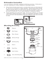
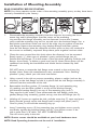
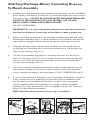
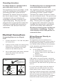
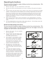
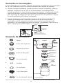
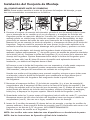
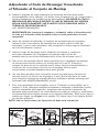
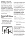
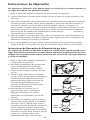
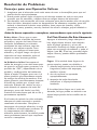
Use & Care Guide
Guía de Cuidado y Uso
Models/Modelos: 587.70235, 70211, 70321, 70351, 70361
Kenmore
®
Food Waste Disposer
Triturador de Alimentos
Sears Brands Management Corporation
Hoffman Estates, IL 60179 U.S.A.
www.kenmore.com
www.sears.com
Sears Canada Inc.
Toronto, Ontario, Canada M5B 2C3
www.sears.ca
®
P/N 560C525P07 RevA
Record Model/Serial
Numbers
Product Record
Bill of sale, sales slip, cancelled check or
other purchase record should be kept
to verify the original purchase date for
warranty purposes.
Model Number:*
Serial Number:*
Purchase Date:
Table of Contents
Record Model/Serial Numbers ..........2
Warranty Information ......................2
Important Safety Instructions ............3
Removal of Old Disposer...................4
Dishwasher Connection.....................5
Installation of Mounting Assembly ....5-7
Electrical Connections .......................8
Operating Instructions .....................8-9
Troubleshooting ..............................10
Cleaning and Maintenance................11
*Above information appears on the label
affixed to bottom of the disposer. For
your convenience, write down the model
and serial numbers prior to installation.
Warranty Information
KENMORE LIMITED WARRANTY
FROM THE DATE OF SALE for the model numbers and time periods listed below, this
product is warranted against defects in material or workmanship.
70235, 70211 - 2 YEARS, 70321 - 3 YEARS, 70351 - 5 YEARS, 70361 - 7 YEARS
WITH PROOF OF SALE, return a defective product to the retailer from which it was
purchased for free replacement.
This warranty is void if this product is ever used for other than private household
purposes.
This warranty gives you specific legal rights, and you may also have other rights which
vary from state to state.
Sears Brands Management Corporation, Hoffman Estates, IL 60179
Sears Canada Inc., Toronto, Ontario, Canada M5B 2C3
Sears Installation Service
To order and schedule professional installation of this disposer, call 1-800-4-MYHOME (800-469-4663)
2
IMPORTANT SAFETY INSTRUCTIONS
Read all instructions before using this appliance
See insert for specific information about you new disposer
NOTE: This Food Waste Disposer has
CAUTION: Be sure to review SAFETY
been designed to operate on 110120 Volt, 60Hz exclusively. Using any
other voltage or Hz adversely affects
performance.
INSTRUCTIONS FIRST PERTAINING TO
A RISK OF FIRE, ELECTRICAL SHOCK
OR INJURY TO PERSONS before using
disposer.
IMPORTANT: Read all instructions
thoroughly. Keep this guide for future
reference.
INSTRUCTIONS PERTAINING TO A RISK OF FIRE, ELECTRIC SHOCK
OR INJURY TO PERSONS. SAVE THESE INSTRUCTIONS.
NOTE: If you are not familiar with electrical power and procedures, call a qualified
electrician.
WARNING: Improper connection of the equipment-grounding conductor can result
in a risk of electric shock. Check with a qualified electrician or serviceman if you are
in doubt as to whether the appliance is properly grounded. Do not modify the plug
provided with the appliance if it will not fit the outlet, have a proper outlet installed
by a qualified electrician.
WARNING: When using electrical appliance, basic precautions should always be
followed, including the following:
1. Read all instructions before using the appliance.
2. To reduce the risk of injury, close supervision is necessary when an a appliance
is used near children.
3. Do not put fingers or hands into a waste disposer.
4. Turn the power switch to the off position before attempting to clear a jam or
remove an object from the disposer.
5. When attempting to loosen a jam in a waste disposer, use a long wooden
object such as a wooden spoon or the wooden handle of a broom or mop.
6. When attempting to remove objects from a waste disposer use long-handled
tongs or pliers. If the disposer is magnetically actuated, non-magnetic tools
should be used.
7. To reduce the risk of injury by materials that may be expelled by a waste
disposer, do not put the following into a disposer: clam or oyster shells, caustic
drain cleaners or similar products; glass, china or plastic; large whole bones;
metal, such as bottle caps, tins cans, aluminum foil or utensils; hot grease or
other hot liquids; whole cornhusks.
8. When not operating the disposer, leave the stopper in place to reduce the risks
of objects falling onto the disposer.
9. For proper grounding instructions see the ELECTRICAL CONNECTION portion of
this manual.
Save these instructions for future reference
3
Removal Of Old Disposer
TYPICAL INSTRUCTIONS, YOUR MODEL MAY VARY.
A
BA
B
E
DC
ED
EF
E
G
IMPORTANT: Unless you have a new home, this is a good time to clean out
the trap and drain lines by running a drain auger or plumber’s snake before
installing your new disposer.
A
B
B
C
D
C
.
C
D
E
1.Unplug the disposer or turn off the electrical power at the circuit breaker or fuse box.
2.Use a pipe wrench to disconnect the drain line where it attaches to the disposer discharge elbow (see B).
3.If a dishwasher is installed, make sure the dishwasher is not running (We recommend unplugging the dishwasher or turning off the electrical power at the circuit breaker or fuse box) then remove the dishwasher drain hose from the disposer (see C).
4.Remove disposer from sink flange by turning lower mount ring to the left (see D). If you are unable to turn the mount ring, tap on one of the extensions from the ring with a hammer. Some mounting systems have tubular extensions. Inserting a screwdriver into one tube will provide additional leverage for turning the mount ring (See D). Some disposers may require the removal of a clamp.
CAUTION: Be sure to support the disposer while performing this step or it may fall when the lower mounting ring is disconnected from the mounting assembly. If your disposer is hard wired (metal shielded cable not utilizing a wall plug), complete steps E and F. If you utilize a plug-in cord, go on to step G.
5.When the disposer is removed, turn it upside down and remove the electrical cover plate (see E).
6.Using a screwdriver, loosen the green ground screw and remove the green ground wire. Remove the wire nuts from the black and white power wires and separate the disposer wires from power cable wires. Loosen the screws on cable clamp and separate cable from disposer (see F).
7. If the existing sink flange is to be re-used, go to page 6.
8.If replacing a 3-bolt style mount system, loosen the 3 mount screws and push the lower mount ring up. Under it is the snap ring. Use a screwdriver to remove the snap ring (see G). Remove the mount ring, backup flange and gasket from the
sink flange.
9.EZ mount systems may require the unscrewing of a large ring holding the sink flange in place. Once unscrewed you can remove the flange.
10.Remove the old sink flange from the sink. Clean the sink thoroughly.
4
Dishwasher Connection
If you are utilizing a dishwasher, complete the following procedure. If dishwasher is
not to be connected go to section Installation of Mounting Assembly.
A. Using a blunt instrument (steel punch or wooden dowl), knock out entire plug (see
A). Do not use a screwdriver or sharp instrument. When knockout plug falls into
disposer, you may remove it or simply grind it up when the disposer is used. This
will not damage the disposer in any way, but may take some time to grind over
the course of several uses. Go to section Installation of Mounting Assembly.
B. Connect dishwasher hose using hose clamp. If hose size is different, you will need
a Dishwasher Connector Kit (see B). Make sure all plumbing connections are tight
and in accordance with all plumbing codes and ordinances. Run water and check
for leaks.
B
*AIR GAP
DISHWASHER
HOSE
A
KNOCK
OUT PLUG
DISPOSER
RUBBER
HOSE
*Air gap may not be required
for all installations. Check local
plumbing codes.
Mounting Assembly
1
Stopper
SINK
SINK
2
3
4
Sink Flange
PLUMBER’S
PUTTY
A
SINK FLANGE**
STOPPER*
RIDGE
SINK FLANGE**
Fiber Gasket
PLUMBER’S
PUTTY
Backup Flange
FIBER GASKET
RIDGE
BACKUP FLANGE
FIBER GASKET
SCREWS
BACKUP FLANGE
MOUNTING
RING
5
6
Mounting Ring
MOUNTING RING
SNAP RING
SNAP RING
LOWER
MOUNTING
RING
Screws
HUSH
CUSHION ®
7
Snap Ring
8
Hush Cushion
RUBBER
GASKET
RESET BUTTON
9
Lower Mounting Ring
* Batch Feed Stopper looks different than the stopper
illustrated.
** Mount
Assembly
** Mount Assembly
NOTE: Hush Cushion is included between mounting ring and lower mounting ring.
5
Installation of Mounting Assembly
READ COMPLETELY BEFORE STARTING
NOTE: Pay close attention to the order of the mounting assembly parts, as they have been
correctly assembled by the factory.
A
2
7
D
E
3
2
2
4
B
5
C
6
1.
Disassemble the mounting assembly from the disposer by turning the lower mount ring until it disengages from the ramps on the mounting ring and the sink flange assembly can be removed. Loosen the 3 mount screws until the mounting ring can be moved up to the backup flange. Use a flat blade screwdriver under one end of the snap ring to remove it from the sink flange. Remove the mounting ring, backup flange and fiber gasket from the sink flange. Note the sequence of these parts as they are stacked in the correct re-assembly sequence. Keep these parts together and set aside.
2.
Clean the area around the sink drain where the disposer is to be mounted. Evenly apply ½” thick rope of plumber’s putty around flange (see A).
Position the sink flange (2) in the center of the sink drain opening. Push the sink flange down firmly to make a good seal (see B). Note: Excess putty will be squeezed out during the installation and should not be cleaned up until
the end
DO NOT move or rotate the sink flange once seated or the seal may be broken. Note: Some sink manufacturers may recommend “Non- Staining” plumber’s putty; check your sink care instructions.
3.
Using a towel in the sink to prevent scratching, place a weight (such as the disposer) on the sink flange to hold it in place until the sink flange assembly is secured from the underside of the sink.
4.
Reassemble the fiber gasket, (3) backup flange (4) and mounting ring, (6), making sure the fiber gasket is on top of the backup flange, and that the backup flange is on top of the mounting ring (see C). They must be in this order! From underneath the sink flange, place the gasket/flange/ring assembly, gasket on top, onto the sink flange (see D).
5.
Holding all 3 parts up against the sink, pull the snap ring (7) open and press firmly into the groove on the sink flange until it snaps into place (see D).
Once in place, it will hold the mounting ring up.
6.
Insert 3 mounting screws (5) into mounting ring and tighten screws evenly and firmly against the backup flange (see E). Use shorter screws if the sink is more than 3/8” thick. DO NOT OVERTIGHTEN! Trim off excess putty in the sink.
NOTE: Shorter screws should be available at your local hardware store.
NOTE: Read Operating Instructions at the end of installation.
6
Attaching Discharge Elbow/ Connecting Disposer
To Mount Assembly
1.
Install the provided discharge elbow/gasket assembly (these are pre-assembled at the factory) and flange as shown in “A”. Install and tighten two screws evenly with a screw driver. DO NOT RE-USE THE EXISTING DISCHARGE ELBOW AND GASKET AS THE GASKET MAY NOT SEAL PROPERLY. USE THE NEW ELBOW, GASKET, FLANGE AND SCREWS PROVIDED.
DO NOT OVERTIGHTEN!
IMPORTANT: Do not remove the gasket and place it on the disposer between the elbow and disposer. It must stay on the elbow to make a proper seal.
2.
Before connecting the disposer to the mounting assembly under the sink, check that the lower mounting ring is in place on the top of the disposer, and that the hush cushion is engaged securely around the top lip of the disposer (see B).
3.
Align the discharge elbow with the drain connection and hang the disposer by aligning the 3 mounting tabs on the lower mounting ring with the slide-up ramp on the mounting ring (see C).
4.
Turn the lower mounting ring until all 3 mounting tabs lock over the ribs at the top of the ramp (see D). If you are unable to turn the mount ring by hand, insert a screw driver through one of the tubes on the lower mounting ring to provide extra leverage to turn it.
5.
Use a pipe wrench to reconnect the discharge elbow to the drain line (see E). (the reversal of page 3, step B) Use a pipe wrench to secure the drain line where it attaches to disposer discharge tube. DO NOT OVERTIGHTEN (see E).
6.
If you are connecting to a dishwasher, go to “Dishwasher Connection” on page 5. If not, remove any tools, packaging or materials used for installation from the sink. Make sure all plumbing connections are tight and in accordance with all plumbing codes and ordinances (If in doubt, contact a qualified plumber). Run water and check for leaks (see Leaks on page 10). Then go to page 8 for the electrical connection.
NOTE: Read Operating Instructions at the end of installation.
RUBBER
GASKET
B
A
A
C
D
LOWER MOUNT RING TUBE
D
E
A
HUSH
LOWER
CUSHION MOUNTING
RING
RAMP
C
7
D
Grounding Instructions
For Waste Disposers equipped with a
grounded plug-in power cord
For Waste Disposers not equipped with
a grounded plug-in power cord
This appliance must be grounded. In the
event of a malfunction or breakdown,
grounding provides a path of least
resistance for electric current to reduce
the risk of electric shock. This appliance
is equipped with a cord having an
equipment-grounding conductor and
a grounding plug. The plug must be
plugged into an appropriate outlet that
is properly installed and grounded in
accordance with all local codes and
ordinances.
This appliance must be grounded. In the
event of a malfunction or breakdown,
grounding provides a path of least
resistance for electric current to reduce
the risk of electric shock. The power cord
(to be installed) must have an equipmentgrounding conductor and a grounding
plug. The plug must be plugged into
an appropriate outlet that is properly
installed and grounded in accordance
with all local codes and ordinances.
Disconnect electric power to disposer
circuit before installation. Turn the
circuit breaker to the OFF position or
remove the fuse.
Electrical Connections
Connecting Disposer to a Plug-In
Cord
1. Connect disposer to 110-120 Volt, 60Hz
AC current only.
2. If plug-in cord is used, use a three prong
plug (see A). Ground wire should be
attached to the ground screw in the
bottom of the end bell (see B).
Wiring Disposer Directly to
House Current
This appliance must be connected to a
grounded, metal permanent wiring system or
an equipment grounding conductor must be
run with the circuit conductors and connected
to the equipment-grounding terminator or
lead on the appliance.
A.
3. Use a cable clamp strain relief connector
where the power cord enters the
disposer (see C).
Trace lead connected to this blade
and attach that lead to white wire
on disposer .
A
RIBBED SIDE
NOTE: When viewing face of electical
plug with grounding pin at top,
the larger left blade is connected to
the identified wire .
B
C
RED RESET BUTTON
GROUND SCREW
TO HOUSE
CURRENT OR
POWER CORD
STRAIN
RELIEF
WIRE NUTS
REMOVE COVER
PLATE
NUT
If you use BX cable:
1. Install cable connector in hole.
2. Connect white wire to white lead of disposer.
3. Connect black.
4. Connect bare ground.
If BX cable is not used, provide a separate
ground wire to nearest cold water metal pipe
or other suitable ground, using the screw in
the bottom of the end bell for the ground wire
(see C).
B. If your power supply does not include a
ground wire, you must provide one unless
metal cable is used. Attach a copper wire
securely to disposer ground screw and attach
other end of wire to a metal cold water pipe.
Use only UL approved ground clamp. If
plastic pipe is used in your home, a qualified
electrician should install a proper ground.
8
Operating Instructions
The Anti-Jam Swivel Impellers make a clicking sound as they swing into place. This
indicates normal operation.
1. Remove sink stopper. Turn on a medium flow of cold water.
2. Turn the wall switch to the ON position; your motor is turning at full speed and ready to
use.
3. Scrape in food waste, like table scraps, peelings, rinds, seeds, pits, small bones and coffee
grounds. To speed up food waste disposal, cut or break up large bones, rinds and cobs.
Large bones and fibrous husks require considerable grinding time and are more easily
thrown away with other trash. Do not be alarmed that the disposer slows down while
grinding. The disposer is actually increasing torque (grinding power) and is operating
under normal conditions.
4. Before turning disposer off, let water and disposer run for approximately 15 seconds
after shredding stops. This assures that all waste is thoroughly flushed through trap and
drain.
5. It is not recommended to use hot water while running disposer. Cold will keep waste and
fats solid so the disposer can flush away particles.
Batch Feed Operating Instructions
The Anti-Jam Swivel Impellers make a clicking sound as they swing into place. This
indicates normal operation. For batch food operation, the sink stopper can be used
to bypass the wall switch to start the disposer.
1. Remove sink stopper. Turn on a medium
flow of cold water.
2. Scrape in food waste, like table scraps,
peelings, rinds, seeds, pits, small bones
and coffee grounds (see A).
3. Insert stopper to start disposer (see B).
One of the two smalls slots in stopper
base must line up with switch plunger
inside the neck of the disposer. Push
down firmly to turn the disposer on. Lift
stopper to shut the disposer off.
4. Run disposer for 15 seconds after
shredding stops. This assures that all
waste is thoroughly flushed through the
drain.
5. To fill sink, insert stopper and align
the largest slot with the switch plunger
(see C). Push down to seal sink without
starting the disposer. When the medium
sized slot (see B) in stopper base is lined
up with the switch plunger, water can
drain but tableware, etc., cannot be
accidently dropped into disposer.
9
Troubleshooting
Tips for Successful Operation
1. Be sure disposer is empty before using your dishwasher so it may drain properly.
2. You may want to leave the stopper in the drain when not in use to prevent utensils
and foreign objects from falling into the disposer.
3. Your disposer is ruggedly built to give you many years of trouble free service. It
will handle all normal food wastes, but it will NOT grind or dispose of such items
as plastic, tin cans, bottle caps, glass china, leather, cloth, rubber, string, clam and
oyster shells, aluminum foil or feathers.
Before seeking repair or replacement, we recommend that you review the
following:
Loud Noises: (Other than those during
grinding of small bones and fruit pits):
These are usually caused by accidental
entry of a spoon, bottle cap or other
foreign object. To correct this, turn
off electrical switch and water. After
disposer has stopped, remove object with
long handled tongs.
Unit Does Not Start: Unplug power
cord or turn either the wall switch or
breaker box switch to “OFF” position,
depending on your model and wiring
configuration. Remove stopper. Check
to see if grinding mechanism turntable
will rotate freely using a wooden broom
handle. If turntable rotates freely, check
reset button to see if it has been tripped.
Re-set button is red and located opposite
discharge elbow, near the bottom (see A).
Push button in until it clicks and remains
depressed.
If re-set button has been tripped, check
for a short or broken wire connecting to
disposer. Check electrical power switch,
fuse box or circuit breaker. If wiring and
electrical components are intact, the unit
may have internal problems that require
service or replacement.
If Turntable Does Not Rotate Freely:
Turn off disposer, then check for any
foreign object lodged between the
grinding mechanism turntable and grind
ring. Dislodge object by rotating table
with a wooden broom handle and remove
object (see 8B). If no foreign object is
present, there may be internal problems.
Leaks: If the unit leaks at the top, it may
be due to:
1. Improper seating of sink flange
(gasket centering, putty or
tightening).
2. Support ring not tightened properly.
3. Defective or improperly installed
hush cushion.
If unit leaks at the waste elbow, leak may
be due to improper tightening of elbow
flange screws.
10
Cleaning and Maintenance
DO NOT ATTEMPT TO LUBRICATE YOUR DISPOSER
The motor is permanently lubricated. The Mineral deposits in water can form on
disposer is self cleaning and scours its
the grinding mechanism turntable, giving
internal parts with each use.
the appearance of rust. DO NOT BE
ALARMED. The turntable is made of
stainless steel and will not corrode.
NEVER put lye or chemical drain cleaners
into the disposer as they cause serious
corrosion of metal parts. If used, resulting
damage can be easily detected and all
warranties are void.
Notes
11
12
Registro de los Números Tabla de Contenidos
de Modelo/Serial
Registro de los Números de Modelo/Serial.....2
Registro de Producto
La carta de venta, comprobante de
compra, cheque cancelado u otro tipo
de registro deberá ser guardado para
verificar la fecha original de compra
para los fines de la garantía.
Modelo Número:*
Serial Número:*
Información de Garantía...............................2
Instrucciones Importantes de Seguridad.........3
Remoción de la Antigua Unidad.....................4
Conexión al Lavaplatos.................................5
Instalación del Conjunto de Montaje............5-7
Conexiones Eléctricas....................................8
Instrucciones de Operación.........................8-9
Resolución de Problemas............................10
Limpieza y Mantenimiento..........................11
Fecha de Compra:
*La Información anterior aparece fijada
en la parte inferior del triturador. Para
su conveniencia, escriba los números
del modelo y serial previo a la
instalación.
Información de la Garantía
GARANTÍA LIMITADA KENMORE
DESDE LA FECHA DE VENTA para los números de modelo y los periodos de tiempo
clasificados a continuación, tiene garantía en contra de los defectos en materiales
o mano de obra.
70235, 70211 - 2 AÑOS, 70321 - 3 AÑOS, 70351 - 5 AÑOS, 70361 - 7 AÑOS
CON LA PRUEBA DE VENTA, devuelva un producto defectuoso al comerciante del
cual fue adquirido para un reemplazo gratis.
Esta garantía es nula si este producto es alguna vez usado para otros
propósitos que no sean los domésticos privados.
Esta garantía le otorga derechos específicos legales, y usted puede también tener
otros derechos los cuales varían de estado a estado.
Sears Brands Management Corporation, Hoffman Estates, IL 60179
Sears Canada Inc., Toronto, Ontario, Canada M5B 2C3
Servicio de Instalación Sears
Para ordenar y programar una instalación profesional de este triturador, llame
al 1-800-4-MY-HOME (800-469-4663)
13
INSTRUCCIONES IMPORTANTES DE SEGURIDAD
Lea todas las instrucciones antes de usar este artefacto
Vea el inserto para información específica sobre su nuevo triturador
NOTA: Este Triturador de Alimentos
PRECAUCIÓN: Asegúrese de
ha sido diseñado para operar
exclusivamente en 110- 120 Volt,
60Hz. Usar otro voltaje o Hz afecta
negativamente su desempeño.
revisar LAS INSTRUCCIONES DE
SEGURIDAD PRIMERO
PERTENECIENTES AL RIESGO DE
INCENDIO, DESCARGA ELÉCTRICA O
DAÑOS A LAS PERSONAS antes de
usar el triturador.
IMPORTANTE: Lea completamente
todas las instrucciones. Guarde esta
guía para futura referencia.
INSTRUCCIONES PERTENECIENTES AL RIESGO DE INCENDIO, DESCARGA
ELÉCTRICA O DAÑOS A LAS PERSONAS. GUARDE ESTAS INSTRUCCIONES.
NOTA: Si no está familiarizado con la energía eléctrica y sus procedimientos,
llame a un electricista calificado.
ADVERTENCIA: La conexión inapropiada del conductor a tierra del equipo
puede resultar en un riesgo de descarga eléctrica. Chequee con un electricista
calificado o reparador si tiene dudas respecto a si el artefacto está bien puesto a
tierra. No modifique el enchufe provisto con el artefacto si éste no se ajustase con el
tomacorriente, tenga un tomacorriente instalado apropiadamente por un electricista
calificado.
ADVERTENCIA: Cuando use artefactos eléctricos, deberá seguir siempre las
precauciones básicas, incluyendo las siguientes:
1. Lea todas las instrucciones antes de usar el artefacto.
2. Para reducir el riesgo de lesión, es necesaria la supervisión cercana cuando un
artefacto es usado cerca de los niños.
3. No ponga los dedos o manos dentro del triturador.
4. Ponga el interruptor de energía en la posición de apagado en el intento de
limpiar un atasco o remover un objeto del triturador.
5. Cuando intente aflojar un atasco en un triturador, use un objeto largo de madera
tales como una cuchara de madera o el mango de madera de un trapeador.
6. Cuando intente remover objetos de un triturador, use tenazas o alicates de mango largo. Si el triturador está accionado magnéticamente, deberían ser usadas herramientas no magnéticas.
7. Para reducir el riesgo de lesiones por materiales que pudieran ser expelidos por
un triturador, no ponga lo siguiente dentro del triturador: conchas de ostras o
almejas; limpiadores de drenaje cáustico o productos similares; vidrio, porcelana o plástico; huesos enteros grandes; metal, tales como botellas, latas, papel aluminio o utensilios; grasa caliente u otros líquidos calientes; hojas de maíz enteras.
8. Cuando no opere el triturador, deje el tapón en su lugar para reducir los riesgos
de que los objetos caigan dentro del triturador.
9. Para las instrucciones apropiadas sobre puesta a tierra, vea el fragmento de
CONEXIONES ELÉCTRICAS de este manual.
Guarde estas instrucciones para futura referencia
14
Remoción del Antiguo Triturador
INSTRUCCIONES TÍPICAS, SU MODELO PUDIERA VARIAR.
A
BA
B
E
DC
ED
EF
E
G
IMPORTANTE: A menos que tenga un nuevo hogar, es buen momento para
limpiar las líneas de sifón y de drenaje dejando correr un drenaje sinfín o
destatascador antes de instalar su nuevo triturador.
A
B
B
C
D
C
.
C
D
E
A. Desenchufe el triturador o apague la energía eléctrica en el interruptor protector o
caja de fusibles.
B. Use una llave de tubo para desconectar la línea de drenaje donde se adjunta al codo de descarga del triturador (vea B).
C. Si un lavavajillas está instalado, asegúrese que el lavavajillas no esté funcionando
(recomendamos desconectar el lavaplatos o apagar la energía eléctrica en el
interruptor protector o caja de fusibles) luego remueva la manguera de drenaje del
lavaplatos del triturador (vea C).
D. Remueva el triturador de la brida del fregadero girando el aro de montaje a la
izquierda (vea D). Si es incapaz de girar el aro de montaje, golpee ligeramente una
de les extensiones del aro con un martillo. Algunos sistemas de montaje tienen
extensiones tubulares. Insertar un destornillador dentro de un tubo proporcionará un
apalancamiento adicional para girar el aro de montaje (Vea D). Algunos trituradores
pueden requerir la remoción de una abrazadera.
PRECAUCIÓN: Asegúrese de soportar al triturador mientras desarrolla este paso o
puede caerse cuando el aro de montaje inferior esté desconectado del conjunto de
montaje. Si su triturador es alambrado (cable reforzado de metal sin utilizar un
enchufe de pared), complete los pasos E y F. Si usted utiliza un cordón de enchufe,
vaya al paso G.
E. Cuando el triturador sea removido, póngalo boca abajo y quite la placa cubierta
eléctrica (vea E).
F. Usando un destornillador, afloje el tornillo de tierra verde y remueva el cable de
tierra verde. Remueva las tuercas para cable de los cables de energía negro y blanco y separe los cables del triturador de los cables de energía. Afloje los tornillos de la abrazadera del cable y separe el cable del triturador (vea F).
G. Si la brida del fregadero va a ser reutilizada, vaya a la página 6.
H. Si reemplaza un sistema de montaje de 3 pernos, afloje los 3 tornillos de montaje
levante el aro de montaje inferior. Bajo éste está el anillo de retén. Use un
destornillador para remover el anillo de retén (vea G). Remueva el aro de montaje, la brida de respaldo y el empaque de la brida del fregadero.
I. Los sistemas de montaje EZ pueden requerir el destornillamiento de un aro grande que soporta la brida del fregadero en su lugar. Una vez destornillada usted puede
remover la bridae.
J. Remueva la brida antigua del fregadero del fregadero. Limpie completamente el fregadero.
15
Conexión al Lavavajillas
Si está utillizando un Lavavajillas, complete el siguiente procedimiento. Si el lavavajillas
no va a ser conectado, vaya a la sección Instalación del Conjunto de Montaje.
A. Usando un objeto contundente (punzón de acero o clavija de madera), quite por
completo el opérculo (vea A). No use un destornillador o instrumento filoso. Cuando el opérculo se salga del triturador, puede quitarlo o simplemente elévelo cuando el triturador sea usado. Esto no dañará el triturador en ninguna forma, pero toma algo de tiempo para que triture sobre el curso de varios usos. Vaya a la sección Instalación del Conjunto de Montaje.
B. Conecte la manguera del lavavajillas usando la abrazadera del cable. Si el
tamaño de la manguera es diferente, necesitará un Kit de Conexión del Lavavajillas (vea B). Asegúrese que todas las conexiones de plomería estén apretadas y en concordancia con todos los códigos y ordenanzas. Deje correr el agua y chequee por posibles fugas.
B
* *AIR
BRECHA
GAP
DE AIRE
MANGUERA DEL
DISHWASHER
LAVAVAJILLAS
HOSE
A
KNOCK
OPÉRCULO
OUT PLUG
TRITURADOR
DISPOSER
MANGUERA
RUBBER
DE
GOMA
HOSE
* La brecha
airenot
puede
no ser
*Air gapdemay
be required
requerida
todas las instalaciones.
for allpara
installations.
Check local
Chequee
los códigos
plumbing
codes.locales de plomería.
Conjunto de Ensamble
1
Tapón
FREGADERO
SINK
2
Brida del Fregadero
3
Empaque de Fibra
BRIDA
DEL
SINK FLANGE**
FREGADERO**
MASILLA
DE
PLUMBER’S
PLOMERIA
PUTTY
RESALTE
RIDGE
EMPAQUE
DE FIBRA
FIBER GASKET
4
Brida de Respaldo
BRIDA
DEFLANGE
RESPALDO
BACKUP
TORNILLOS
SCREWS
ARO
DE MONTAJE
MOUNTING
RING
5
6
Aro de Montaje
ANILLO
DE RETÉN
SNAP RING
ARO DE
MONTAJE
INFERIOR
Tornillos
COJÍN
SILENCIADOR
7
Aro de Retén
8
Cojín Silenciador
BOTÓN DE REINICIO
9
Aro de Montaje Inferior
** Conjunto de Montaje
** Mount Assembly
NOTA: El Cojín silenciador está incluido entre el aro de montaje y el aro de montaje inferior.
16
Instalación del Conjunto de Montaje
LEA COMPLETAMENTE ANTES DE COMENZAR
NOTA: Preste mucha atención al orden de las piezas del conjunto de montaje, ya que
han sido ensambladas correctamente en la fábrica.
2
D
7
E
F
3
2
2
4
B
5
6
C
B. Desarme el conjunto de montaje del triturador girando el aro de montaje inferior hasta
que se desacople de los resaltes en el aro de montaje y el conjunto de la brida del
fregadero pueda ser removido. Afloje los 3 tornillos de montaje hasta que el aro de
montaje pueda ser subido hasta la brida de respaldo. Use un destornillador de hoja
plana bajo un extremo del anillo de retén para removerlo de la brida del fregadero.
Remueva el aro de montaje, la brida de respaldo y el empaque de fibra de la brida del
fregadero Tenga en cuenta la secuencia de estas partes ya que están apiladas en la
secuencia correcta de reensamblaje. Mantenga estas piezas juntas y puestas a un lado.
Limpie el área alrededor del drenaje del fregadero donde el triturador vaya a ser
montado. Aplique uniformemente ½” de cordón grueso de masilla de plomería alrededor
de la brida (vea A). Posicione la brida del fregadero (2) en el centro de la abertura del
drenaje del fregadero. Oprima firmemente hacia abajo la bridra del fregadero para
hacer un buen sello (vea B). Nota: El exceso de masilla será aplastado durante la
instalación y no deberá ser limpiado hasta el final.
NO mueva o rote la brida del fregadero una vez asentada o el sello puede romperse.
Algunos fabricantes de fregaderos pueden recomendar masilla de plomería
“Anti manchas”; chequee las instrucciones de cuidado de su fregadero.
Usando una toalla en el fregadero para prevenir rasguños, coloque un peso (tales como
un triturador) sobre la brida del fregadero para mantenerla en lugar hasta que el
montaje de la brida del fregadero esté asegurada desde la parte inferior
del fregadero.
C. Reconecte el empaque de fibra, (3) la brida de respaldo (4) y el aro de montaje,(6),
asegurándose que el empaque de fibra esté en la cima de la brida de respaldo y que
la brida de respaldo esté en la cima del aro de montaje (vea C). ¡Deben de estar en este
orden! Desde por debajo de la brida del fregadero, coloque el montaje de empaque/
brida/aro, el empaque en la parte superior sobre la brida del fregadero (vea D).
D. Sosteniendo todas las 3 partes contra el fregadero, hale el anillo de retén (7) y presione
firmemente dentro del riel sobre la brida del fregadero hasta que haga un sonido de
acoplamiento (vea D). Una vez en su lugar, sostendrá el aro de montaje.
E. Inserte los 3 tornillos de montaje (5) dentro del aro de montaje y apriete los tornillos de
manera uniforme y firme contra la brida de respaldo (vea E). Use tornillos más cortos si el
fregadero es de más de 3/8” de grosor. ¡NO APRIETE DEMASIADO!
Recorte el exceso de masilla en el fregadero.
NOTA: Los tornillos más cortos deberían estar disponibles en su tienda local de partes.
NOTA: Lea las Instrucciones de Operación al final de la instalación.
17
Adjuntando el Codo de Descarga/ Conectando
el Triturador al Conjunto de Montaje
A. Instale el conjunto de codo/empaque de descarga provisto (estos están preensamblados en la fábrica) y la brida como se muestra en “A”. Instale todo y
apriete firmemente dos tornillos con un destornillador. NO REUSE EL CODO Y
EMPAQUE DE DESCARGA EXISTENTE YA QUE EL EMPAQUE NO PUDIERA
SELLAR APROPIADAMENTE. USE EL NUEVO CODO, EMPAQUE, BRIDA Y
TORNILLOS PROPORCIONADOS.
¡NO APRIETE DEMASIADO!
IMPORTANTE: No remueva el empaque y colóquelo sobre el triturador entre
el codo y el triturador. Debe quedarse sobre el codo para hacer un sello
apropiado.
B. Antes de conectar el triturador al conjunto de montaje bajo el fregadero,
chequee que el aro inferior de montaje esté en lugar sobre la cima del
triturador, y que el cojín silenciador esté acoplado en forma segura alrededor
del silo del triturador (vea B).
C. Alinee el codo de descarga con la conexión de drenaje y cuelgue el
triturador alineando las 3 lengüetas de montaje sobre el aro de
montaje inferior con el riel deslizante sobre el aro de montaje (vea C).
D. Gire el aro de montaje inferior hasta que todas las 3 lengüetas de montaje
se cierren sobre las nervaduras en la cima del riel (vea D). Si usted es
incapaz de girar el aro de montaje con la mano, inserte un destornillador a
través de uno de los tubos sobre el aro de montaje inferior para
proporcionar un apalancamiento extra para girarlo.
E. Use una llave de tubo para reconectar el codo de descarga a la línea de
drenaje (vea E). (lo inverso de la página 3, paso B) Use una llave de tubo
para asegurar la línea de drenaje donde se adjunte al tubode descarga del
triturador. NO APRIETE DEMASIADO (vea E).
F. Si lo está conectando al lavavajillas, vaya a “Conexión al Lavavajillas” en la
página 5. Si no, remueva cualquier herramienta, embalaje o materiales usados
para la instalación del fregadero. Asegúrese que todas las conexiones de
plomería estén apretadas y en concordancia con todos los códigos y ordenanzas
de plomería(Si tiene dudas, contacte a un plomero calificado). Deje correr agua y
cheque por fugas (vea Fugas en la página 10). Luego vaya a la página 8 para
la conexión eléctrica.
NOTA: Lea las Instrucciones de Operación al final de la instalación.
A
A
EMPAQUE
RUBBER
DE GOMA
GASKET
B
D
C
D
E
A
COJÍN
ARO DE
SILENCIADOR MONTAJE
INFERIOR
C
18
D
Instrucciones de Puesta a Tierra
Para Trituradores equipados con un
cable de energía con puesta a tierra
Este artefacto debe estar puesto a
tierra. En el escenario de una falla o
avería, la puesta a tierra proporciona
un pase de menos resistencia para la
corriente eléctrica y así reducir el riesgo
de descarga eléctrica. Este artefacto
está equipado con un cable que tiene un
equipo conductor de puesta a tierra y
un enchufe de puesta a tierra. El enchufe
debe ser conectado en un tomacorriente
apropiado que esté instalado
apropiadamente y puesto a tierra en
concordancia con todos los códigos y
ordenanzas locales.
Conexiones Eléctricas
Conectando el Triturador a un Cable de
Enchufe
1. Conecte el triturador solamente a una
corriente de 110-120 Volt, 60Hz.
2. Si se usa un cable de enchufe, use un
enchufe de tres picos (vea A). El cable
de puesta a tierra deberá ser adjuntado
al tornillo de puesta a tierra en la parte
inferior de la campana final (vea B).
3. Use un conector de alivio de tensión
donde el cable de corriente se introduce
al triturador (vea C).
Rastree
el cable
conectadotoathis
establad
hojae
Trace
lead connected
y adjunte
ese cable
cable
blanco
en
and attach
that allead
to white
wire
el triturador.
on disposer .
LADO
RIBBEDREFORZADO
SIDE
NOTA:
vea la cara
NOTE:Cuando
When viewing
facedel
of elenchufe
ectical
eléctrico
congrounding
el pin depin
tierraat en
plug with
top,la
cima,
la hojaleft
izquierda
grandeto
the larger
blade ismás
connected
está
al cable
theconectada
identified wire
. identificado.
B
C
BOTÓN ROJO
RED RESET BUTTON
DE REINICIO
TORNILLO
A
GROUND SCREW
TIERRA
ATOCORRIENTE
HOUSE
CASERA
CURRENTO OR
CABLE
POWER CORD
DE ENERGÍA
ALIVIO
STRAINDE
TENSIÓN
RELIEF
TUERCAS DE
WIRE NUTS
CABLE
PLACA
REMOVECUBIERTA
COVER
DE
REMOCIÓN
PLATE
A
TUERCA
NUT
Para Trituradores no equipados con un
cable de energía con puesta a tierra
Este artefacto debe estar puesto a tierra.
En el escenario de una falla o avería, la
puesta a tierra proporciona un pase de
menos resistencia para la corriente
eléctrica y así reducir el riesgo de
descarga eléctrica. El cable de energía
(a ser instalado) debe tener un equipo
conductor de puesta a tierra y un
enchufe de puesta a tierra. El enchufe
debe ser conectado en un tomacorriente
apropiado que esté instalado
apropiadamente y puesto a tierra en
concordancia con todos los códigos y
ordenanzas locales.
Desconecte la energía eléctrica al
circuito del triturador antes de la
instalación. Ponga el interruptor
protector en la Conexiones Eléctricas
posición de OFF o quite el fusible.
Cableando el Triturador Directamente
a la Corriente de la Casa
Este artefacto debe ser conectado a
un sistema de cableado puesta a tierra
permanente de metal o un equipo conductor
de puesta a tierra, debe ser puesto en
funcionamiento con los conductores del circuito
y conectado al terminador o cable del equipo
de puesta a tierra en el artefacto.
A. Si usted usa un cable BX:
1. Instale el cable conector en el hoyo.
2. Conecte el alambre blanco al cable blanco del triturador.
3. Conecte el negro.
4. Conecte el puesta a tierra desnudo.
Si el cable BX no es usado, provéase de un
cable de puesta a tierra separado de la
tubería de metal de agua fría más cercana
y otro puesta a tierra adecuado, usando el
tornillo de la campana final para el alambre
de puesta a tierra (vea C).
B. Si su suministro de energía no incluye
un alambre de puesta a tierra, debe
proporcionar uno a menos que un cable
metálico sea usado. Adjunte un alambre de
cobre en forma segura al tornillo de puesta
a tierra del triturador y adjunte el otro
extremo del alambre a la tubería metálica
de agua fría. Use solamente una abrazadera
de puesta a tierra aprobada por la UL. Si
se usa una tubería de plástico en su hogar,
un electricista calificado debería instalar un
puesta a tierra en forma apropiada.
19
Instrucciones de Operación
Los Impulsores Giratorios Anti Atasco hacen un sonido de clic cuando quedan en
su lugar. Esto indica una operación normal.
1. Quite el tapón del fregadero. Encienda con un flujo medio de agua fría.
2. Ponga el interruptor de pared en la posición de ON; su motor irá a toda velocidad y listo para usar.
3. Deje triturar desperdicios de comida. Baje por el drenaje alimentos de desecho, peladuras, cáscaras de frutas, semillas, pepas, huesos pequeños y granos de café. Para acelerar el triturado de alimentos, corte o rompa los huesos grandes, cáscaras y mazorcas. Los huesos grandes y cáscaras fibrosas requieren un tiempo considerable de molido y son más fáciles que las tire con el resto de la basura. No se alarme si el triturador baja la velocidad mientras muele. En realidad está aumentando la torsión (energía de molido) y está operando en condiciones normales.
4. Antes de apagar el triturador, deje correr agua y al triturador por aproximadamente 15 segundos después que la trituración se detenga. Esto asegura que todo el desperdicio sea desechado a través de la trampa y el drenaje.
5. No es recomendable usar agua caliente mientras funciona el triturador. El frío mantiene sólidos el desecho y las grasas para que así el triturador pueda desechar las partículas.
Instrucciones de Operación de Alimentación por Lotes
Los Impulsores Giratorios Anti Atasco hacen un sonido de clic cuando quedan en su
lugar. Esto indica una operación normal. Para la operación de alimentación porlotes,
el tapón del fregadero puede usarse para pasar por encima del interruptor depared
e iniciar el triturador.
1. Quite el tapón del fregadero. Encienda con
un flujo medio de agua fría.
2. Deje triturar desperdicios de comida. Baje
por el drenaje alimentos de desecho,
peladuras, cáscaras de frutas, semillas,
pepas, huesos pequeños y granos de café
(vea A).
3. Inserte el tapón para iniciar el triturador
(vea B). Una de las dos ranuras pequeñas en
la base del tapón debe alinearse con el
émbolo interruptor dentro del cuello del
triturador. Empuje firmemente para
encender el triturador. Levante el tapón
para apagar el triturador.
4. Deje funcionar el triturador por 15
segundos luego que la trituración se
detenga. Esto asegura que todo el
desperdicio sea desechado a través del
drenaje.
5. Para llenar el fregadero, inserte el tapón y
alinee la ranura más grande con el émbolo
interruptor (vea C). Empuje para sellar el
fregadero sin iniciar el triturador. Cuando la
ranura de tamaño mediano (vea B) en la
base del tapón esté alineada con el émbolo
interruptor, el agua puede drenarse, pero la
vajilla, etc., no puede dejarse caer
accidentalmente dentro del triturador.
20
RANURA
MEDIANA
RANURA
GRANDE
RANURA
PEQUEÑA
Resolución de Problemas
Consejos para una Operación Exitosa
1. Asegúrese que el triturador esté vacío antes de usar su lavavajillas para que así
pueda drenar apropiadamnte.
2. Usted puede querer dejar el tapón en el drenaje cuando no está en uso para
prevenir que los utensilios y objetos diversos caigan dentro del triturador.
3. Su triturador está construido en forma resistente para darle muchos años de servicio
libre de fallas. Manejará todos los desperdicios de alimentos normales, pero NO
molerá o desechará artículos como plástico, latas, tapas de botella, vidrio,
porcelana, cuero, prendas, cuerda, conchas de ostras o almejas, papel aluminio o
plumas.
Antes de buscar reparación o reemplazo, recomendamos que revise lo siguiente:
Ruidos Altos: (Otros que no sean
aquellos durante el molido de huesos
pequeños y pepas de fruta): Estos son
causados usualmente por entrada
accidental de una cuchara, tapa de
botella u otro objeto externo. Para
corregir esto, apague el interruptor
eléctrico y el agua. Luego de que el
triturador se haya detenido, quite el
objeto con unas tenazas grandes.
Si el Plato Giratorio No Rota Libremente:
La Unidad no Inicia: Desconecte el
cable de energía ya sea del interruptor
de pared o el interruptor protector a la
posición de “OFF”, dependiendo de su
modelo y configuración del cableado.
Quite el tapón. Chequee para ver si el
plato giratorio gira libremente usando
un mango de escoba de madera. Si el
plato giratorio rota libremente, chequee
el botón de reinicio por si haya sido
activado. El botón de reinicio es rojo y
está ubicado al opuesto del codo de
descarga, cerca del fondo (vea 8A).
Presione el botón hasta que dé un clic y
permanezca oprimido.
Fugas: Si la unidad tiene fugas en la
parte superior, puede ser debido a:
1. Asiento inapropiado de la brida del
fregadero (centro del empaque,
masilla o ajuste).
2. Aro de soporte no apretado
apropiadamente.
3. Montaje del cojín silenciador
defectuoso o inapropiadamente
instalado.
Si el botón de reinicio ha sido activado,
chequee el cable acortado o partido
conectado al triturador. Chequee el
interruptor de energía eléctrica, la caja
de fusibles o el interruptor protector. Si
los componentes del cableado y
eléctricos están intactos, la unidad puede
tener problemas internos que requieran
servicio o reemplazo.
Apague el triturador, luego chequee si
hay algún objeto diverso está alojado
entre el plato giratorio y el aro de
trituración. Desaloje el objeto girando el
plato con un mango de madera y quite el
objeto (vea 8B). Si no hay presente algún
objeto diverso, pueden haber problemas
internos.
Si la unidad tiene fugas en el codo de
desecho, la fuga puede ser debido a un
ajuste inapropiado de los tornillos de la
brida.
BOTÓN DE
REINICIO
21
NÚMERO
DE SERIAL
Limpieza y Mantenimiento
NO INTENTE LUBRICAR SU TRITURADOR
El motor está permanentemente
lubricado. El triturador es autolimpiante
y restrega sus piezas internas con cada
uso.
NUNCA ponga lejía o limpiadores
químicos drenadores dentro del triturador
ya que causan una seria corrosión de las
piezas metálicas. Si son usados, el daño
resultante puede ser fácilmente
detectado y todas las garantías serán
nulas.
Notas
22
Pueden formarse depósitos minerales en
el agua sobre el plato giratorio del
mecanismo de trituración, dándole la
apariencia de óxido. NO SE ALARME.
El plato giratorio está hecho de acero
inoxidable y no se corroerá.
23