1
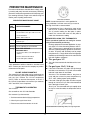
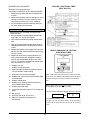
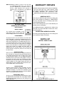
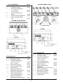
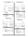
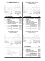
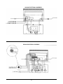
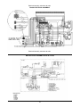
SERIES 2000 FRYER MANUAL
INSTANT RECOVERY® GAS FRYER
READ AND SAVE THIS MANUAL FOR FUTURE REFERENCE
Record the Model No. and Serial of this Instant Recovery® Gas Fryer in the space provided below.
Serial No. __________________________
Model No. __________________________
Keep these numbers for future reference
IMPORTANT: Keep a copy of your bill of sale. The date on the bill establishes the warranty period should service be required. If service is performed, it is in your interest to obtain and keep all receipts. Keating commercial fryers are intended for other than household use.
CONTENTS:
Important Safety Instructions . . . . . . . . . . . . . . .i
INTRODUCTION . . . . . . . . . . . . . . . . . . . . . . . .1
INSTALLATION
Damage During Shipment . . . . . . . . . . . . . . . . .1
FIRST STEPS
Positioning . . . . . . . . . . . . . . . . . . . . . . . . . . . . .1
Ventilation . . . . . . . . . . . . . . . . . . . . . . . . . . . . .1
National Code Requirement . . . . . . . . . . . . . . .1
Gas Connectors & Pipe Size . . . . . . . . . . . . . .2
Flexible Gas Connection & Quick Disconnect
Devices . . . . . . . . . . . . . . . . . . . . . . . . . . . . . . .2
Restraining Devices . . . . . . . . . . . . . . . . . . . . .2
Electrical Connection . . . . . . . . . . . . . . . . . . . .2
Leveling . . . . . . . . . . . . . . . . . . . . . . . . . . . . . . .3
PLACING YOUR KEATING FRYER IN OPERATION
Filling . . . . . . . . . . . . . . . . . . . . . . . . . . . . . . . . .3
Lighting . . . . . . . . . . . . . . . . . . . . . . . . . . . . .3-5
Cooking . . . . . . . . . . . . . . . . . . . . . . . . . . . . .5-6
Shutdown . . . . . . . . . . . . . . . . . . . . . . . . . . . . .6
Oil Breakdown . . . . . . . . . . . . . . . . . . . . . . . . . .6
Draining . . . . . . . . . . . . . . . . . . . . . . . . . . . . . . .6
Cleaning and Boil-Out . . . . . . . . . . . . . . . . . .6-8
OPERATOR SELF HELP CHECK LIST
8
PREVENTATIVE MAINTENANCE
Preventive Maintenance Chart . . . . . . . . . . . . .9
Hi-Limit Check Bi-Monthly . . . . . . . . . . . . . . . . .9
Thermostat Calibration . . . . . . . . . . . . . . . . . . .9
Thermostat Bulb Positioning . . . . . . . . . . . . . . .9
Timer . . . . . . . . . . . . . . . . . . . . . . . . . . . . . . . .10
WARRANTY REPAIRS
Ordering Parts . . . . . . . . . . . . . . . . . . . . . . . . .11
Parts List . . . . . . . . . . . . . . . . . . . . . . . . . .11-15
Wiring Diagrams . . . . . . . . . . . . . . . . . . . .15-18
This Owner’s Guide provides specific operating instructions for your model. Use the Instant Recovery®
Fryer only as instructed in this Service Guide.
Versión en español
Si desea obtener usa copia en español de estes Manual del Usario, sirvase escribir la dirección que
se incluye a continuadión.
1-800-KEATING
w w w. k e a t i n g o f c h i c a g o . c o m
Gas Fryer 2000
08/11
Purchaser should post in a prominent location instructions to
be followed in the event the user smells gas. This information
shall be obtained by consulting the local gas supplier.
Improper installation,
adjustment, alteration,
service or maintenance
can cause property
damage, injury or death.
Read the installation,
operating and maintenance
instructions thoroughly
before installing or
servicing this equipment.
FOR YOUR SAFETY
Do not store or
use gasoline or
other flammable
vapors or liquids
in the vicinity of
this or any other
appliance.
WARNING
WARNING
PROPANE GAS MAY EVENTUALLY
LOSE ITS ODOR AND PRECAUTIONS SHOULD BE TAKEN TO
ASSURE THAT PROPANE GAS IS
NOT PRESENT EVEN THOUGH YOU
DO NOT DETECT AN ODOR. IF
THERE IS ANY DOUBT, YOU
SHOULD CALL YOUR LOCAL
PROPANE GAS SUPPLIER FOR
ASSISTANCE.
IF NOT INSTALLED, OPERATED AND
MAINTAINED IN ACCORDANCE
WITH THE MANUFACTURER'S
INSTRUCTIONS, THIS PRODUCT
COULD EXPOSE YOU TO SUBSTANCES IN FUEL OR IN FUEL
COMBUSTION WHICH CAN CAUSE
DEATH OR SERIOUS ILLNESS AND
WHICH ARE KNOWN TO THE STATE
OF CALIFORNIA TO CAUSE CANCER, BIRTH DEFECTS OR OTHER
REPRODUCTIVE HARM.
THE EQUIPMENT IS TO BE
INSTALLED TO COMPLY WITH THE
BASIC PLUMBING CODE OF THE
BUILDING OFFICIALS AND CODE
ADMINISTRATORS INTERNATIONAL,
INC. (BOCA) AND THE FOOD SERVICE SANITATION MANUAL OF THE
FOOD AND DRUG ADMINISTRATION
(FDA).
*As continuous product improvement occurs, specifications may be changed without notice.
i
INTRODUCTION
FIRST STEPS
Instructions in this manual should be read thoroughly
before attempting to operate this Keating Gas Fryer. All
installation and service on Keating equipment must be
performed by qualified, certified, licensed and/or authorized installation or service personnel.
POSITIONING
Keep appliance area free and clear of any combustibles. Position the Keating Gas Fryer 6 inches
(152mm) from any combustible material. A minimum of
24 inches (610mm) should be provided at the front of
the Keating Gas Fryer for servicing and proper operation. Air for combustion enters the fryer from the bottom
of the cabinet and the bottom of the control panel.
Operating information for Keating equipment has been
prepared for use by qualified and/or authorized personnel.
DO NOT BLOCK BOTTOM OF KEATING INSTANT
RECOVERY® GAS FRYER CABINET. DO NOT
OBSTRUCT FLUE.
Your Keating Instant Recovery® Gas Fryer is designed
to be serviced from the front.
Keating equipment is made in the U.S.A. and has
American sizes of hardware. All metric conversions are
approximate.
INSTALLATION INSTRUCTIONS
MINIMUM CLEARANCE
Proper installation will assure top performance. Alteration to your equipment will void the warranty. Before
uncrating, check equipment carefully for damage.
Clearances
IF EQUIPMENT ARRIVES DAMAGED
Keating does not assume responsibility for loss or
damage incurred in transit.
IMPORTANT
This merchandise has been thoroughly inspected and
carefully packed before leaving our plant. Responsibility for its safe delivery was assumed by the carrier at
the time of shipment. Claims for loss or damage to the
contents should, therefore, be made upon the carrier,
as follows:
Combustible
Noncombustible
Construction
Construction
Back
6"
0"
Right Side
6"
0"
MINIMUM CLEARANCE
Left Side
6"
0"
SUITABLE FOR COMBUSTIBLE FLOORS VENTILATION
The Keating Gas Fryer must be installed in an area
providing adequate air supply and ventilation. Do not
obstruct the flow of combustion and ventilation air.
Proper ventilation is one of the important considerations for efficient operation of the Keating Gas Fryer. It
should be installed so that the products of combustion
are removed efficiently without producing drafts that
will interfere with proper burner operation. The intake
for the exhaust fan should not be placed close to the
flue of the Keating Gas Fryer to insure proper air flow
necessary for combustion. The area around the front
and bottom of the Keating Gas Fryer must be kept
clear and unobstructed. In the U.S.A. the ventilation
systems must conform to the ANSI/NFPA96 latest edition. “A minimum of 18" (457mm) should be maintained
between the flue outlet and the lower edge of the
grease filters.” Must be installed at least 16" away from
any open flame. It is the responsibility of the owner and
the local installer to comply with national and local
codes.
CONCEALED LOSS OR DAMAGE
Concealed loss or damage means loss or damage
which does not become apparent until the merchandise has been unpacked. The contents may be damaged in transit due to rough handling even though the
carton may not show external damage. When the damage is discovered upon unpacking, make a written
request for inspection by the carrier’s agent within fifteen days of the delivery date. Then file a claim with the
carrier since such damage is the carrier’s responsibility. By following these instructions carefully, we guarantee our full support of your claims to protect you against
loss from concealed damage.
VISIBLE LOSS OR DAMAGE
Any external evidence of loss or damage must be
noted on the freight bill or express receipt, and signed
by the carrier’s agent. Failure to adequately describe
such external evidence of loss or damage may result in
the carrier refusing to honor a damage claim. The form
required to file such a claim will be supplied by the carrier.
NATIONAL CODE REQUIREMENT
The installation must conform with local codes, or in the
absence of local codes, with the National Fuel Gas
code, ANSI Z223.1 or the Natural gas Installation
Code, CAN/CGA-B149.1 or the Propane Installation
Code, CAN/CGA-B149.2. Flexible connectors must
comply to ANSI Z221.69/CAN/CGA1.16. Keating
equipment is designed and manufactured to operate
DO NOT RETURN DAMAGED MERCHANDISE
TO KEATING. FILE YOUR CLAIM AS ABOVE.
1
only on the type of gas specified by the user and indicated on the serial plate located inside the door. The
gas may be natural, propane or manufactured. The
type of gas cannot be converted to another gas fuel by
turning or engaging a switch.
If more than one gas unit is on the same supply line,
you may require a larger line. Consult your local gas
company to assure adequate volume and pressure.
Refer to serial plate for proper gas requirement for your
particular model.
GAS CONNECTIONS AND PIPE SIZE
A single Keating Gas Fryer requires a standard gas
pipe size of 3/4 inch (19mm) I.D. connection. Multiple
fryers with a common manifold will require a minimum
of 1 1/4 inch I.D. gas supply line. The size of the gas
supply pipe is very important. If the pipe is too small
you will have low gas pressure at the Keating Gas
Fryer manifold. Low gas pressure will cause slow
recovery and/or delayed ignition. If you have a question
about gas pipe size call your local gas company.
FLEXIBLE GAS CONNECTORS AND QUICK DISCONNECT DEVICES
For an appliance equipped with casters:
The installation shall be made with a connector that
complies with the Standard for Connectors for Movable
Gas Appliances, ANSI Z21.69 or the Standard for Connectors for Moveable Gas Appliances, CAN/CGA-6.16,
and a quick disconnect device that complies with the
Standard for Quick-Disconnect Devices for Use With
Gas Fuel, ANSI Z21.41 or the Standard for Quick Disconnect Devices for Use with Gas Fuel, CAN1-6.9.
CAUTION
RESTRAINING DEVICES
1.) Adequate means must be provided to limit the
movement of the appliance without
depending on the connector and the
quick-disconnect device or its associated piping to limit the appliance
movement.
Before connecting new pipe to the Keating Gas Fryer
the pipe must be blown out to remove all foreign particles. These particles in the controls or burners may
cause improper or dangerous operating conditions.
CAUTION
Fryer must also be restrained to prevent tipping when installed so that hot
liquid splashing is avoided.
Pipe joint compounds that are used on threaded joints
of appliance piping shall be resistant to the action of liquefied petroleum gases (Loctite PST 56765). When
using pipe joint compound do not apply to the first two
threads. Use only very small amount and only on male
threads. This will prevent clogging of burner orifices
and the gas valve. Never use compound on female
threads as it might be pushed into the gas valve.
2.) The restraint means must be
attached to the rear of the Keating Gas Fryer within 2"
of the center line width and approximately 1-5/8" from
the bottom of the cabinet back to allow the restraining
bolt to be anchored to the cabinet back between the
cabinet bottom and inner liner.
IF DISCONNECTION OF THE RESTRAINT IS NECESSARY, IT MUST BE RECONNECTED WHEN THE
KEATING GAS FRYER IS RETURNED TO ITS ORIGINALLY INSTALLED POSITION.
Have your installer check for gas leaks using a soap
and water solution before operating. DO NOT USE AN
OPEN FLAME TO CHECK FOR GAS LEAKS.
1) The Keating Gas Fryer and its individual shut off
valves must be disconnected from the gas supply piping system during any pressure testing of that system
at test pressures in excess of 1/2 psi (3.45kPa) (13.84
in WC) High pressure can damage the gas valve causing a hazardous condition.
INSTALLATION
The installer is responsible for attaching the tipping
restraint.
ELECTRICAL CONNECTION
The Keating Gas Fryer, when installed, must be electrically grounded in accordance with local codes, or in
the absence of local codes, the National Electrical
Code, ANSI/NFPA No. 70. or the Canadian Electrical
Code, CSAC-22.2 as applicable. A wiring diagram is
located on the last page. In the U.S.A. and Canada, the
electrical supply must be 120 VAC, 60
Hz.
2.) The appliance must be isolated from the gas supply
piping system by closing its individual manual shutoff
valve during any pressure testing of the gas supply piping system at test pressures equal to or less than 1/2
psi (3.45 kPa).
NOTE: Line pressure must be kept
below 10” (Nat), 13” (LP) to avoid
damage to the gas valve.
WARNING
The required gas pressure for proper
operation of each fryer is 4" water column for natural gas and 10" water column for propane gas at the burner
manifold.
This appliance is equipped with a
three-prong 120 Volt NEMA 5-15
(grounding) plug for your protection
against shock hazard and should be
plugged directly into a properly
grounded and polarized three-prong
2
THIS FRYER MAY NOT BE ALTERED, MODIFIED
OR CHANGED IN ANY WAY.
receptacle. Do not cut or remove the grounding prong
from this plug. (Model AA has no electric connection).
LEVELING
FILLING
NOTE: Before filling the fryer make certain the fryer
vessel is sanitized, dry and the drain valve is
completely closed.
NOTE: We recommend that solid shortening not be
used in a Keating Gas Fryer if it is not equipped with a
melt cycle. If solid shortening is used, it should be melted prior to filling the fryer vessel. Damage done by
melting solid shortening in the fryer vessel will void the
warranty.
CAUTION
Oil expands when heated. The “Fill Level” line has
been provided to ensure optimum cooking while ensuring the safety of the operator. Do not overfill the fryer
vessel.
The Keating Gas Fryer will operate at its highest efficiency when properly leveled. Place a level on the fryer
from side to side. For fryer on legs, the bottom foot of
the leg is adjustable. Turn counterclockwise to
decrease height, or clockwise to increase height until
level. For fryers with casters, the casters are adjustable
by loosening the jam nut and turn the caster in or out.
When the desired level is reached, tighten the jam nut.
Adjustments of more than 3/4" are not recommended
on any caster. The same procedure should be followed
to level the fryer from front to back.
Fill Level Line
Fill the fryer vessel with oil or MELTED solid shortening
up to the “Fill Level” line.
PLACING KEATING GAS
FRYER IN OPERATION
Never leave your fryer operating unattended.
(When all previous instructions have been completed).
Check the serial plate on the panel (inside cabinet) to
determine if the burner is set up for the proper type gas
before connecting the quick-disconnect or piping from
the building gas supply pipe.
a. Maximum incoming gas pressure
NATURAL GAS – 7 inches W.C. with burners on
LP GAS – 11 inches W.C. with burners on
If a popping noise is heard from the fryer during the
cooking cycle, the following checks must be made in
this order:
CAUTION
BE SURE THE HEAT TRANSFER TUBES ARE COMPLETELY COVERED WITH OIL BEFORE SWITCHING THE FRYER ON. IF OIL LEVEL DROPS BELOW
TOP OF HEAT TRANSFER TUBES, SEVERE DAMAGE TO FRYER AND INJURY TO OPERATOR MAY
RESULT.
LIGHTING INSTRUCTIONS
(See lighting instructions plate attached to the inner
door of Keating Gas Fryer.) Model AA does not
require an electrical connection.
Make sure that the Keating Gas Fryer is plugged in. If
not your fryer will not operate. Make sure that the main
gas valve on the gas supply line to the Keating Gas
Fryer is in the “ON” position.
b. Fryer manifold gas pressure
NATURAL GAS – 4 inches W.C. with burners on
LP – 10 inches W.C. with burners on
ALWAYS disconnect fuel source and power
supply before servicing.
NEVER move a fryer when full of oil.
NEVER introduce objects or liquids into fryer,
while operational, which are not designed or
made for cooking.
3
NOTE: Unless you have an AA model your fryer cannot
be operated during a power failure.
AA MODELS OPERATING INSTRUCTIONS
START-UP PROCEDURE
WARNING: DO NOT START FRYER WITHOUT
FIRST FILLING FRYER POT.
STEP 1. Set thermostat to the "OFF" position.
STEP 2. Turn "MAIN POWER" switch to the "OFF"
position.
STEP 3. Turn gas valve knob to "PILOT" position.
STEP 4. Light constant pilot located on left side of
pilot runner tube.
STEP 5. Push and hold the gas valve knob for 30 seconds and release.
STEP 6. With the pilot still on, turn gas valve knob to
the "ON" position.
STEP 7. Set thermostat to desired temperature, turn
"MAIN POWER" switch to the "ON" position.
The burners will come on.
AA CONTROL PANEL
BB CONTROL PANEL
HIGH LIMIT TEST PROCEDURE (All Models):
DO BI-MONTHLY
STEP 1. Place a suitable thermometer in the oil on
the front left corner of the fryer 2" from the
top to check temperature.
STEP 2. Set thermostat to 375°F after burners go off.
Push and hold the "HIGH LIMIT TEST"
switch. The burners will come on.
STEP 3. When 425°F is reached the burners go off.
Now it is ok to release test switch.
STEP 4. If the high limit thermostat does not shut
down the burners between 425°-450°F as
read on the thermometer, the high limit must
be replaced immediately.
STEP 5. To re-start the fryer it must be cooled down to
cooking temperature and the red reset button on the high limit thermostat pushed.
Return to STEP 3 in the start-up procedure.
34×24 BB CONTROL PANEL
34×24 TS CONTROL PANEL
SHUTDOWN PROCEDURE
STEP 1. Set thermostat to the "OFF" position.
STEP 2. Turn "MAIN POWER" switch to the "OFF"
position.
STEP 3. Turn gas valve knob to the "OFF" position.
STEP 4. Turn gas supply valve to the "OFF" position.
STEP 5. Check to make sure all burners and pilot are
out.
TS CPU CONTROL PANEL
BB MODELS OPERATING INSTRUCTIONS
START-UP PROCEDURE
AIR IN THE GAS SUPPLY LINE MAY REQUIRE A
LONGER THAN NORMAL PERIOD OF TIME TO
LIGHT YOUR FRYER DURING INITIAL INSTALLATION OR AFTER OVERNIGHT SHUTDOWN
WARNING: DO NOT START FRYER WITHOUT
FIRST FILLING FRY POT.
4
Select "MELT" with solid shortening until liquid shortening is 1" from full mark then
switch to the "FRY" position. Burners will
come on.
STEP 1. Set "MELT-IDLE-FRY" switch to "IDLE" position and thermostat to the "OFF" position.
STEP 2. Turn "MAIN POWER" switch to the "ON"
position.
STEP 3. Hold the "PUSH TO LIGHT" switch in until
the amber "PILOT ON" light comes on.
STEP 4. Set thermostat to desired temperature.
STEP 5. Set "MELT-IDLE-FRY" switch to "FRY." The
burners will come on. Select "MELT" with
solid shortening until liquid shortening is 1"
from full, then switch to the "FRY" position.
HIGH LIMIT TEST PROCEDURE: DO BI-MONTHLY
STEP 1. Place a suitable thermometer in the oil on
the front left corner of the fryer 2" from the
top to check temperature.
STEP 2. Set thermostat to 375°F after burners go off.
Push and hold the "HIGH LIMIT TEST"
switch. The burners will come on.
STEP 3. When 425°F is reached the burners go off
and the "OVER MAX TEMP" red light will
come on. Release test switch.
STEP 4. If the high limit thermostat does not shut
down the burners between 425°-450°F as
read on the thermometer, the high limit must
be replaced.
STEP 5. To re-start the fryer it must be cooled down to
cooking temperature and the red reset button on the high limit thermostat pushed. The
red light will go off. Return to STEP 3 in the
start-up procedure.
HIGH LIMIT TEST PROCEDURE: DO BI-MONTHLY
STEP 1. Place a suitable thermometer in the oil on
the front left corner of the fryer 2" from the
top to check temperature.
STEP 2. Set thermostat to 375°F after burners go off.
Push and hold the "HIGH LIMIT TEST"
switch. The burners will come on.
STEP 3. When 425°F is reached the burners go off.
Release test switch.
STEP 4. If the high limit thermostat does not shut
down the burners between 425°-450°F as
read on the thermometer, the High Limit
must be replaced immediately.
STEP 5. To re-start the fryer it must be cooled down to
cooking temperature and the red reset button on the high limit thermostat pushed.
Return to STEP 3 in the start-up procedure.
SHUTDOWN PROCEDURE
STEP 1. Set "MELT-IDLE-FRY" switch to "IDLE" position and thermostat to the "OFF" position.
STEP 2. Turn "MAIN POWER" switch to the "OFF"
position. Its green light will go off.
STEP 3. Turn gas supply valve to the "OFF" position.
STEP 4. Check to make sure all burners and pilot are
out.
COOKING
Keating's Instant Recovery® Gas Fryer is designed to
provide maximum production efficiency and deliver
high quality food products. Low- temperature cooking,
highly polished stainless steel and a true COLD ZONE
mean extended oil life. Follow cooking procedures
below for your model.
TS MODELS OPERATING INSTRUCTIONS
START-UP PROCEDURE
WARNING: DO NOT START FRYER WITHOUT
FIRST FILLING FRYER POT.
STEP 1. Set "MELT-IDLE-FRY" switch to "IDLE" position and thermostat to the "OFF" position.
STEP 2. Turn "MAIN POWER" switch to "ON" position. Its green light and the timers will come
on.
STEP 3. Light constant pilot located on left side of
pilot runner tube.
STEP 4. Hold the "PUSH TO LIGHT" switch for 30
seconds. The pilot runner tube will light.
STEP 5. Set thermostat to desired temperature.
STEP 6. Set "MELT-IDLE-FRY" switch to "FRY" with
oil in the fry pot. The burners will come on.
Cold Zone
5
DRAINING
CAUTION
OPERATION OF THIS FRYER SHOULD BE LIMITED
TO PERSONNEL WHO HAVE BEEN THOROUGHLY
TRAINED IN OPERATING PROCEDURES.
Set thermostat to the desired frying temperature.
CAUTION
CARE SHOULD BE TAKEN WHEN LOWERING
BASKETS INTO FRYER TO PREVENT SPLASHING
HOT OIL FROM FRYER VESSEL.
If your fryer has timers, push “Start-Stop” button of
electronic timer(s). For fryers with automatic basket lift,
basket(s) will lower into fryer vessel.
Operator in safety gear
CAUTION
When timer(s) sounds, carefully lift basket(s) out of hot
oil. For fryers with automatic basket lift, a buzzer will
sound and the basket(s) will rise automatically. Allow oil
to drain before removing.
ALWAYS SHUT THE FRYER OFF COMPLETELY
BEFORE DRAINING. THE FRYER SHOULD BE
DRAINED ONLY UNDER THE SUPERVISION OF
PROPERLY TRAINED PERSONNEL. A DRAIN PIPE
AND COVERED CONTAINER SUITABLE FOR USE
WITH HOT OIL SHOULD BE USED TO ENSURE THE
SAFETY OF THE OPERATOR.
CAUTION
DO NOT LIFT BASKETS DIRECTLY OUT OF THE
FRYER VESSEL WITHOUT DRAINING AS SEVERE
INJURY MAY RESULT
1. Operator should be outfitted with proper attire
including:
USE ONLY KEATING APPROVED BASKETS IN
YOUR FRYER. NEVER OVERFILL FRY BASKETS.
DO NOT BANG BASKETS ON BASKET HANGERS
OR ON FRYER VESSEL.
–Oil and heat resistant gloves
–Oil and heat resistant apron
–Safety goggles
–Oil and heat resistant footwear
Place basket(s) on basket hanger rods on splashback
of fryer and allow to drain.
2. Turn off the fryer and open the door.
SHUTDOWN INSTRUCTIONS
3. Put suitable container under drain valve.
Always turn the fryer off each night.
4. Drain oil from fryer by slowly turning handle. The
drain will be completely open after 1/4 turn.
1. See Shutdown procedure.
5. After fryer drains close the drain valve.
OIL BREAKDOWN
6. Filtering may be done at this step.
As part of a “Preventive Maintenance Program”, the oil
in your fryer needs to be filtered regularly. The initial
investment in the frying system is less than the total
overall costs of oil during the life of the fryer, and with
regular filtering, you can realize substantial savings in
oil costs, as well as, maintenance charges. We have
listed some of the conditions which are catalysts in the
breakdown of oil:
NOTE: Fryers with a central filter will drain differently.
CLEANING AND BOIL-OUT FOR A
SINGLE FRYER
When cleaning and boiling out your fryer use Keating
Sea Powder and Keating Klenzer to keep your fryer in
top condition.
1. Contact with Oxygen
1. Operator should be outfitted with proper attire
including:
2. Carbonization of Crumbs and Food Particles
3. Non-Stainless Steel Surfaces
–Oil and heat resistant gloves
–Oil and heat resistant apron
–Safety goggles
–Oil and heat resistant footwear
4. Keep Salt and Seasonings Away From Oil
5. Prolonged High Temperatures
Turn the fryer off. Remove baskets and screen.
2. Drain oil from fryer, see draining.
6
TO AVOID DAMAGING THE FRYER, DO NOT
POWER WASH, SPRAY OR HOSE IT DOWN WHILE
CLEANING IT.
CAUTION
A KEATING FRYER OR FILTER SHOULD BE DRAINED
ONLY UNDER THE SUPERVISION OF PROPERLY
TRAINED PERSONNEL. WHEN DISCARDING OIL, A
COVERED RECEPTACLE APPROVED FOR USE WITH
HOT OIL SHOULD BE USED. USE OF A NONAPPROVED RECEPTACLE OR METHOD OF DRAINING
THE OIL COULD JEOPARDIZE THE SAFETY OF THE
OPERATOR.
CLEANING AND BOIL-OUT FOR A FRYER WITH
ATTACHED FILTER SYSTEM
When cleaning and boiling out your fryer use Keating
Sea Powder and Keating Klenzer to keep your fryer in
top condition.
3. Remove oil container to a secure area to prevent
accidental spillage.
4. Fill fryer vessel to "Fill Level" line with water.
SAFE & EASY FILTER
(SIDE VIEW)
5. Set thermostat and turn fryer on to bring water to a
gentle boil. Once boil has been reached, turn fryer
off.
CAUTION
UNDER NO CIRCUMSTANCES SHOULD THE
FRYER AND FILTER BE LEFT UNATTENDED DURING BOIL-OUT. TRAINED PERSONNEL MUST BE
PRESENT DURING THE PROCEDURE TO PREVENT BOIL OVER OR TO TURN OFF THE POWER
IF WATER DROPS BELOW HEATING TRANSFER
TUBES.
Connect hose here to discard oil
6. Dissolve 2/3 cup of Keating Sea Powder for every
five gallons of water and let soak for 1/2 hour. If
there is a large build-up of carbonized grease,
allow for fryer to soak overnight.
7. While soaking, a natural fiber brush may be used
to scrub the tubes and inside walls of fryer. Drain
the water and Sea Powder into a dry suitable
receptacle and remove from cooking area. Sprinkle
Keating Klenzer liberally on tubes and sides of
fryer vessel. A non-abrasive scouring pad amy be
used to remove the now softened carbonized
grease. Thoroughly rinse fryer vessel with potable
water to remove all Klenzer. Prior to refilling with
oil, wipe the inside of the fryer vessel making sure
all water and Klenzer have been removed.
CAUTION
A KEATING FRYER OR FILTER SHOULD BE
DRAINED ONLY UNDER THE SUPERVISION OF
PROPERLY TRAINED PERSONNEL. WHEN DISCARDING OIL, A COVERED RECEPTACLE
APPROVED FOR USE WITH HOT OIL SHOULD BE
USED. USE OF A NON-APPROVED RECEPTACLE
OR METHOD OF DRAINING THE OIL COULD JEOPARDIZE THE SAFETY OF THE OPERATOR.
1. Operator should be outfitted with proper attire
including:
NOTE: Do not pump water through the filter system.
–Oil and heat resistant gloves
–Oil and heat resistant apron
–Safety goggles
–Oil and heat resistant footwear
DO NOT DAMAGE OR REPOSITION THERMOSTAT
PROBE AS THIS MAY AFFECT THE ACCURACY OF
THE FRYER.
2. Turn the fryer off.
A cleaning hose and wand have been provided for
discarding oil.
CAUTION
DO NOT MIX WATER AND HOT OIL
3. Attach cleaning hose to quick disconnect located
on the bottom right side of your filter.
8. Close the drain valve.
4. Remove baskets and screen. Drain fryer into the
central filter drawer.
9. Check thermostat bulb positioning.
10. Refill the fryer with new or filtered oil.
7
Wait until filter drawer is cool before cleaning,
approximately 15 minutes.
5. Open the discard valve located near the quick disconnect in the filter cabinet.
15. Remove filter drawer, drain, clean and dry.
6. The hose may now be used to pump the oil into the
shortening handling system and discarded properly.
16. Prepare filter drawer and return to filter cabinet.
7. Remove oil container to a secure area to prevent
accidental spillage.
8. Fill fryer vessel to “Fill Level” line with water.
TO AVOID DAMAGING THE FRYER, DO NOT
POWER WASH, SPRAY OR HOSE IT DOWN WHILE
CLEANING IT.
9. Set thermostat and turn fryer on to bring water to a
gentle boil. Once boil has been reached, turn fryer
off.
17. Pump must be primed with oil after boil-out with
water.
Failure to lubricate pump may cause severe damage to Filter System.
WARNING
UNDER NO CIRCUMSTANCES SHOULD THE
FRYER AND FILTER BE LEFT UNATTENDED DURING BOIL-OUT. TRAINED PERSONNEL MUST BE
PRESENT DURING THE PROCEDURE TO PREVENT BOIL OVER OR TO TURN OFF THE POWER
IF WATER DROPS BELOW HEATING TRANSFER
TUBES.
OPERATOR SELF HELP
Before calling for service, review this list. It may save
you both time and expense. This list includes common occurrences that are not the result of defective
workmanship or materials in this appliance.
10. Dissolve 2/3 cup of Keating Sea Powder for every
five gallons of water and let soak for 1/2 hour. If
there is a large build-up of carbonized grease,
allow fryer to soak overnight.
11. While soaking, a natural fiber brush may be used
to scrub the tubes and inside walls of fryer. Pump
the water and Sea Powder into a dry suitable
receptacle and remove from cooking area. Sprinkle
Keating Klenzer liberally on tubes and sides of
fryer vessel. A non-abrasive scouring pad may be
used to remove the now softened carbonized
grease. Thoroughly rinse fryer vessel with potable
water to remove all Klenzer. Prior to refilling with
oil, wipe the inside of the fryer vessel making sure
all water and Klenzer have been removed.
OCCURRENCE
SOLUTION
Fryer does not
operate:
Check power cord, unit
plugged in?
Thermostat is in the
off position.
Check gas supply.
See figure below.
Reset high limit.
NOTE: For a fryer with a Central, Zero-Space™ Filter,
or Safe & Easy Filter always check the rear drain operating handle before attempting to use the fryer. A safety switch prevents the fryer from operating if the handle
is not pushed in completely and latched. (See figure 32)
DO NOT DAMAGE OR REPOSITION THERMOSTAT
PROBE AS THIS MAY AFFECT THE ACCURACY OF
THE FRYER.
Figure 3-2
Rear Drain Operating Handle
CAUTION
DO NOT MIX WATER AND HOT OIL
12. Close the drain valve and disconnect the cleaning
hose.
Quick disconnect will remain hot for approximately
15 minutes.
13. Check thermostat bulb positioning (should be 1
paper thickness away from heat tube).
14. Refill the fryer with new or filtered oil.
8
PREVENTIVE MAINTENANCE
Preventive maintenance should be done in daily, weekly, monthly and yearly intervals as necessary. Following
preventive maintenance procedures will help keep your
fryer working efficiently. Proper care and servicing will
lead to years of quality performance.
Thermostat calibration
PREVENTIVE MAINTENANCE CHART
TIME
FRAME
Daily*
Weekly*
NOTE: Locate thermometer in same position for
every calibration. Left front corner of fryer vessel at
the High Limit Bulb is recommended.
OPERATOR/OWNER
4. If temperature of fryer is found to be more or less
than 15°F off, remove the thermostat knob. There
are (4) screws holding the dial plate in place.
Loosen the screws and reset the dial plate to
match the thermometer reading.
Check lights and controls.
Check that the oil is up to “Fill Level” Line.
Clean all baskets.
Drain, strain or filter oil.
BEFORE REPLACING, TEST THERMOSTATS
Drain and clean fryer.
Boil-out fryer.
These operational problems can easily be corrected by thermostat bulb positioning.
BiMonthly Hi-Limit & Test procedures.
Monthly*
Keating’s patented thermostat application is accurate within 2°F of the dial setting between 250°F –
350°F. This accuracy is attained only if the thermostat bulb is placed properly against the heat transfer tube. To quickly and accurately test for proper
bulb placement, a single thickness of writing paper
should be pulled through between the tube and the
bulb with medium resistance.*
Check calibration of the thermostat.
Yearly* QUALIFIED SERVICE
PERSONNEL ONLY
Check burner flame color and adjust air
shutters.
Remove and clean all orifices.
Check and replace radiants.
1. *For gas fryers 14":
The end of thermostat bulb should touch the burner tube.
*High production facilities should be checked more
often. Contact your local service company to perform
maintenance and repairs.
2. For gas fryers 10x11, 18 & up:
If the bulb is too loose, the paper will slip through
with little or no resistance. A fryer with a thermostat
bulb that is too loose will overshoot.
HI-LIMIT CHECK BI-MONTHLY
The manual Hi-Limit test button can be used to test the
Hi-Limit Control by pushing and holding the button in
until the fryer reaches the Hi-Limit temperature
(425°F). Place an accurate thermometer in the oil. If
the Hi-Limit Control doesn’t shut off the fryer between
425°F and 450°F, have it replaced.
Overshoot: The thermostat takes a long time to
cycle and then misses its preset temperature by
20°F - 40°F yielding a poor quality product.
If the bulb is too tight, the paper will either not pull
through or it will tear. A fryer with a thermostat bulb
that is too tight will short cycle.
Short Cycle: The thermostat will cycle rapidly while
the fryer is in the idle mode; the temperature will be
erratic.
THERMOSTAT CALIBRATION
You will need:
One screwdriver with 1/8" wide flat blade
One accurate fryer thermometer
1. Set thermostat to desired frying temperature.
2. Allow fryer to cycle three times.
3. Place an accurate thermometer in the oil.
Thermostat Bulb Positioning 10x11, 18 & up Fryer Gas
9
REQUIRED TEST EQUIPMENT:
“KEATING” ELECTRONIC TIMER
(PART # 023709)
Multimeter (for testing continuity)
CHECKING CONTINUITY WITH THE MULTIMETER
1. Rotate the thermostat shaft until an audible click
is heard.
2. Rotate the thermostat shaft left and right ten times
causing the switch to click on and off ten times,
while using the Multimeter to verify continuity.
3. If the switch does not show continuity during all
ten trials, replace the thermostat.
WARNING
Disassembling the thermostat will void the thermostat warranty.
1. Set compression ring onto capillary end of bulb
finger tight, 1/2” from end of capillary.
2. Insert new thermostat bulb through control panel
back.
3. Apply oil resistant flexible sealant onto compression fitting thread before installing fitting into fryer
vessel.
4. Position bent portion of bulb against far right heat
transfer tube and install compression fitting snugly
into fryer vessel.
HOW TO PROGRAM THE “KEATING”
ELECTRONIC TIMER
5. Adjust bulb so at least 2” of bent portion of it is
next to heat transfer tube and tighten compression nut onto compression fitting for fryer 10x11,
18 & up. The end of thermostat bulb should touch
the burner tube for 14" fryers.
6. Replace burners.
7. Replace control panel back.
8. Slide back fabric shield over capillary and carefully coil capillary. Avoid crimping.
9. Reconnect wires to thermostat body.
Make certain power to the timer has been OFF for at least
30 seconds. Then PRESS and hold down the UP arrow button while turning the rocker power switch to the ON position.
10. Replace two screws which hold thermostat body
to control panel.
11. Replace control panel.
12. Replace three retaining screws and washers
which hold dial plate in place.
13. Replace thermostat knob.
Note: If power switch does not turn off timers, the unit must
be unplugged (two people may be needed).
14. Connect electric power source. Turn on gas and
pilots.
The timer will turn ON and the display will now be indicating
15. Boil out fryer.
–
16. Refill fryer with oil to “fill level line”.
17. Start fryer, preheat and calibrate with
thermometer.
–
–
OR
–
••–
–
The BEEPER will BEEP 4 times.
If STEP 1 was OK, proceed to STEP 2. If not, retry Step 1
making sure the power was OFF for at least 30 seconds or
more.
10
STEP 2 PRESS all 3 buttons in sequence: left-center-right.
The BEEPER will BEEP when each button is
pressed. If BEEPER does not BEEP, the timer is
defective. STOP TESTING. Reset procedure is
completed when 1:00 appears on the digital display.
WARRANTY REPAIRS
Keating's warranty begins with the date of installation.
In the event that your Fryer, under warranty, needs
repairs other than routine cleaning, you are requested
to contact KEATING OF CHICAGO, INC.
(1-800-KEATING) before calling a local service company.
1:00
ORDERING PARTS
Parts may be ordered by part number by calling your
local service company or Keating at 1-800-KEATING.
You may also order on-line at Keating’s part store,
www.keatingofchicago.com.
Refer to the Keating Gas Fryer Limited Warranty for
warranty service information.
OPTIONAL TIMER
OPERATING INSTRUCTIONS
PART # 056921
The model/serial plate is located on the inside of the
front door. The serial and model numbers are necessary when ordering.
DIGITAL TIMERS
The electronic timers, standard on TS &
IFM models, provide a clearly visible and
accurate display and are very easy to use.
WARNING AND OPERATING PLATES
All warning and operating plates on the Keating Gas
Fryer should be in place at all times.
PROGRAMMING
To program the timers, the unit must be in the idle mode.
Press and hold the set button for approximately two seconds. The display will show “SEt”. Press the button for the
channel to be programmed. The display will show the current setting for that channel. Use the up or down button to
increment or decrement the setting. When the setting is
correct, press and hold the set button again for approximately two seconds. The display will show "StO" for
approximately two seconds and the timer will return to
normal operation. Repeat the process as necessary for
the other timers.
PARTS LIST
CONTROL PANEL AA GAS
OPERATING LOGIC
When the timer is powered up, the display will show the
time setting for the channel that was operated last and the
relay output contacts will be open. To start a cycle, press
the desired channel button (1-3). The display will begin to
countdown from the preset time setting and the relay output contacts will close. During the countdown the colon
will flash at a one-second rate. When the countdown has
reached "00:00" the relay output contacts will open, the
display will flash, and the audible alarm will sound. To cancel the audible alarm, press any button.
PAUSE FEATURE
To pause a cycle in progress, press any button. The relay
output contacts will open, the display will flash, and the
countdown will pause. To resume the countdown, press
any button. The display will resume the normal countdown
and the relay output contacts will close.
CANCELING A CYCLE
To cancel a cycle in progress press and hold any button
for approximately two seconds. The relay output contacts
will open and the display will show the time setting for the
channel last used.
Corresponds with parts list on page 12
11
QTY. DESCRIPTION
PART #
A
1
THERMOSTAT DIAL PLATE 375°
058037
B
1
THERMOSTAT KNOB
004163
C
1
GAS FRYER THERMOSTAT
D
1
14” 14CM and AA
023145
10x11 18 and up
035553
SWITCH ROCKER WHITE
ON/OFF
035030
E
1
SWITCH ROCKER MOMENTARY
032297
F
1
HIGH LIMIT (RESETTABLE)
GAS
034357
CONTROL PANEL TS GAS
D
F
H
G
I
F
CONTROL PANEL BB GAS
B,C
E
A
TS CONTROL PANEL
J
K
QTY. DESCRIPTION
QTY.DESCRIPTION
P/N
P/N
A
1
THERMOSTAT DIAL PLATE 375°
058037
B
1
THERMOSTAT KNOB
004163
C
1
GAS FRYER THERMOSTAT
A
1
THERMOSTAT DIAL PLATE 375°
058037
14” BB, TS, IFM, CPU
035574
B
1
THERMOSTAT KNOB
004163
10x11, 18” and up
035575
C
1
GAS FRYER THERMOSTAT
D
1
SWITCH ROCKER WHITE
(LIGHT REPLACEMENT KIT)
058328
035575
E
2
DIGITAL TIMER 24V
056921
F
2
SWITCH ROCKER WHITE
032297
14” BB, TS, IFM, CPU
035574
10x11, 18” and up
D
1
SWITCH MELT-IDLE-FRY
032829
E
1
HIGH LIMIT (RESETTABLE)
034357
MOMENTARY
(PUSH TO LIGHT, HIGH LIGHT TEST)
F
1
FLAME SWITCH
037406
G
1
SWITCH ROCKER WHITE
MOMENTARY (PUSH TO LIGHT)
032297
H
021254
I
J
K
G
H
1
INDICATING LIGHT AMBER
J
1
SWITCH ROCKER WHITE
(LIGHT REPLACEMENT KIT)
058328
SWITCH ROCKER WHITE
MOMENTARY (HIGH LIMIT TEST)
032297
K
1
12
1
SWITCH MELT/IDLE/FRY
032829
1
INDICATING LIGHT GREEN
021255
1
INDICATING LIGHT RED
021209
1
HIGH LIMIT (RESETTABLE)
034357
1
FLAME SWITCH
037406
ELECTRICAL BOX ASSEMBLY GAS FRYER
(TS and BB ONLY)
POT ASSEMBLY 14BB & 14TS GAS
(Front Drain Shown)
B
A
C
E
D
F
QTY. DESCRIPTION
A
3 FIN RADIANT
B
1
POT 14” GAS WELDMENT
C
3
BURNER
028048
004553
D
QTY. DESCRIPTION
1
1
TRANSFORMER 120V/240V TO 24V
2 PIN CONNECTOR
032408
032207
C
1
9 PIN CONNECTOR
028303
D
1
FAT MELT 24V
034272
000041
Call 800-KEATING
1
DRAIN VALVE
1
REAR DRAIN VALVE (NOT SHOWN)
016341
E
1
RUNNER PILOT ASSEMBLY
018814
F
1
GAS VALVE NAT. (FRONT DRAIN TS)
LP. (FRONT DRAIN TS)
037237
037238
1
GAS VALVE NAT. (REAR DRAIN TS)
P/N
A
B
P/N
3
037241
LP.
1
POT ASSEMBLY 14AA GAS
(Front Drain Shown)
037242
GAS VALVE NAT. (ALL BB MODELS)
037227
LP.
037228
POT ASSEMBLY 18AA GAS
(Front Drain Shown)
B
A
C
B
A
E
C
E
D
F
QTY. DESCRIPTION
P/N
A
3
3 FIN RADIANT
B
1
POT WELDMENT 14” GAS UNI-POT
Call 800-KEATING
C
3
BURNER
D
E
F
F
000041
QTY. DESCRIPTION
A
4
3 FIN RADIANT
1
POT 18” GAS WELDMENT
4
BURNER
028048
004554
1
DRAIN VALVE 1”
004553
1
REAR DRAIN VALVE (NOT SHOWN)
016341
C
1
RUNNER PILOT TUBE ASSEMBLY
019408
D
GAS VALVE NAT.
LP.
P/N
028048
B
1
D
000041
Call 800-KEATING
1
DRAIN VALVE
023625
1
DRAIN VALVE 2” FRONT
021256
023624
1
REAR DRAIN VALVE (NOT SHOWN)
016342
E
1
RUNNER PILOT ASSEMBLY
000647
F
1
GAS VALVE NAT.
LP.
023625
023624
13
POT ASSEMBLY 18BB & 18TS GAS
(Front Drain Shown)
POT ASSEMBLY 20BB & 20TS GAS
(Front Drain Shown)
B
A
B
A
C
C
E
E
D
F
QTY. DESCRIPTION
4
3 FIN RADIANT
B
1
POT 18” GAS WELDMENT
C
4
BURNER
D
QTY. DESCRIPTION
P/N
A
D
F
A
000041
4
P/N
3 FIN RADIANT
000041
Call 800-KEATING
B
1
POT 20” GAS WELDMENT
028048
C
4
BURNER
Call 800-KEATING
028048
004554
D
1
DRAIN VALVE
004554
1
DRAIN VALVE
1
DRAIN VALVE 2” FRONT
021256
1
DRAIN VALVE 2” FRONT
021256
1
REAR DRAIN VALVE (NOT SHOWN)
016342
1
REAR DRAIN VALVE (NOT SHOWN)
016342
E
1
RUNNER PILOT ASSEMBLY
004243
E
1
RUNNER PILOT ASSEMBLY
004246
F
1
037237
037238
037241
F
1
1
GAS VALVE NAT. (FRONT DRAIN TS)
LP. (FRONT DRAIN TS)
GAS VALVE NAT. (REAR DRAIN TS)
1
GAS VALVE NAT. (ALL BB MODELS)
GAS VALVE NAT. (FRONT DRAIN TS)
LP. (FRONT DRAIN TS)
GAS VALVE NAT. (REAR DRAIN TS)
LP.
GAS VALVE NAT. (ALL BB MODELS)
LP.
037237
037238
037241
037242
037227
037228
LP.
1
037242
LP.
1
037227
037228
POT ASSEMBLY 20AA GAS
(Front Drain Shown)
POT ASSEMBLY 24BB & 24TS GAS
(Front Drain Shown)
B
A
B
A
C
C
E
E
F
F
D
QTY. DESCRIPTION
P/N
A
4
3 FIN RADIANT
B
1
POT 20” GAS WELDMENT
C
4
BURNER
028048
D
1
DRAIN VALVE
004554
1
DRAIN VALVE 2” FRONT
021256
QTY.
5
1
5
1
1
1
E 1
F
1
000041
A
B
C
D
Call 800-KEATING
1
REAR DRAIN VALVE (NOT SHOWN)
016342
E
1
RUNNER PILOT ASSEMBLY
000649
F
1
GAS VALVE NAT.
LP.
D
023625
1
023624
1
14
DESCRIPTION
P/N
3 FIN RADIANT
000041
POT 24” GAS WELDMENT Call 800-KEATING
BURNER
028048
DRAIN VALVE
004554
DRAIN VALVE 2” FRONT
021256
REAR DRAIN VALVE (NOT SHOWN)
016342
RUNNER PILOT ASSEMBLY
004579
GAS VALVE NAT. (FRONT DRAIN TS) 037237
LP. (FRONT DRAIN TS)
037238
GAS VALVE NAT. (REAR DRAIN TS)
037241
LP.
037242
GAS VALVE NAT. (ALL BB MODELS)
037227
LP.
037228
AA2000 ELECTRICAL ASSEMBLY
BB2000 ELECTRICAL ASSEMBLY
15
Electrical Assembly not shown to scale
TS2000 ELECTRICAL ASSEMBLY
Electrical Assembly not shown to scale
BB ELECTRICAL ASSEMBLY WITH SE FILTER
16
TS ELECTRICAL ASSEMBLY WITH SE FILTER
BASKET LIFT ELECTRICAL ASSEMBLY (ALL FRYERS)
17
PROBLEM
Fryer overshoots
temperature setting.
PROBABLE CAUSE
SOLUTION
a. Thermostat bulb improperly
placed.
a. Adjust bulb position. See page 9 –
Thermostat Bulb Positioning.
b. Thermostat out of calibration.
b. Calibrate thermostat. See page 9 –
Calibration.
Oil in fryer vessel smokes. a. Oil has begun to breakdown.
a. Replace oil.
b. High carbon content in oil.
b. Filter oil completely, replace if
necessary.
c. Dirty fryer vessel.
c
d. Inferior grade of oil.
d. Check with supplier for the grade of oil
needed for your cooking applications.
e. Fryer is overheating.
e. Check calibration of thermostat (See
page 9) and replace if necessary.
a. Over-filling fryer with oil.
a. Fill fryer up to “Fill Level” Line as oil
will expand when heated.
b. Product overloaded in fryer
vessel.
b. Follow recommended cooking
production figures in determining
proper size of loads.
c. Oil breakdown causing foaming.
c. Replace oil.
d. Water in the cold zone.
d. Stir oil repeatedly with a paddle until
water boils off. Filter oil. If necessary,
allow oil to cool. Drain about one quart
of it to remove remaining water.
a. Connections are loose or
electronic timer is faulty.
a. Make sure connections are tight.
Replace timer if faulty.
b. Motor limit switch is faulty.
b. Replace limit switch or straighten arm.
c. Lift motor is faulty.
c. Replace motor. Specify left or right side
motor when ordering.
d. Basket lift relay is faulty.
e. Actuator is defective
d. Replace relay.
e. Replace Actuator
Basket lift motor runs, but
basket does not move.
a. Cam is slipping on motor shaft.
a. Tighten cam onto motor shaft.
Runner bar will not light
a. (For AA units) - gas valve knob
in incorrect position.
a. Rotate gas valve knob to PILOT
position. Depress and hold for 30
seconds.
b. Reset High Limit
Fryer vessel boiling over.
Basket lift mechanism
will not operate.
b. (BB and TS units) Hi Limit
tripped.
Burners with not light
a. (For AA units) gas valve knob in
incorrect position.
b. (BB and TS units) switch not
set to fry.
18
Boil-out fryer.
a. Rotate gas valve knob to ON. Turn
power switch ON. Set thermostat to
desired temperature
b. Set MELT/IDLE/FRY switch to FRY.
Set thermostat to desired temperature.
SERVICE INFORMATION
If you have a service related question call 1-800-KEATING.
Please state the nature of the call; it will ensure speaking with the appropriate person.
Have your serial and model number available when ordering parts.
KEATING OF CHICAGO, INC.
8901 West 50th Street, McCook, Illinois 60525-6001
Phone: (708) 246-3000 FAX: (708) 246-3100
Toll Free 1-800-KEATING (In U.S. and Canada)
www.keatingofchicago.com
KEATING LIMITED WARRANTY CARD
PLEASE COMPLETE AND MAIL AT ONCE–WARRANTY IS NOT IN EFFECT UNTIL CARD IS RETURNED.
WARRANTY CARD IS ALSO AVAILABLE TO COMPLETE ON LINE AT YOUR CONVENIENCE.
COMPANY: __________________________________________________________________________________________________________________
ADDRESS: __________________________________________________________________________________________________________________
CITY: ______________________________________________________________________________ STATE: ________________ ZIP: ____________
DEALER: ____________________________________________________________________________________________________________________
DATE OF PURCHASE: ________________________________________________________________ INVOICE NUMBER: ____________________
SERIAL NUMBER: ________________________________________
FRYER
FILTER SYSTEM
GRIDDLE
REMARKS: ______________________________________________
TOP-SIDE COOKER
HOT PLATE
PASTA PLUS
I HAVE READ THE INSTALLATION AND OPERATION INSTRUCTIONS.
SIGNED: __________________________________________________________________________________ DATE: __________________________
Serving Those Who Serve The Very Best