1
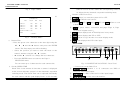
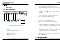
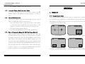
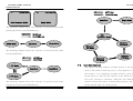
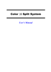
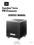
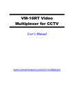
JV-TV5020
USER’S MANUAL
CUSTOMER SERVICE INFORMATION
JWIN New York Office 51-41 59th Pl.,
Woodside, NY 11377 USA
Toll Free Number:
1-866-807-JWIN
E-mail:
[email protected]
8-CHANNEL QUAD SPLITTER
JV-TV5020 USER’S MANUAL
USER’S MANUAL
JV-TV5020
outlet. Do not defeat the safety purpose of the polarized plug.
CAUTION
6-2.
RISK OF ELECTRIC SHOCK DO NOT OPEN
Other Keys
① FREEZE : Enables selected channel freezes in QUAD mode,
FULL mode, MODE function.
CAUTION : TO REDUCE THE RISK OF ELECTRIC SHOCK DO NOT
REMOVE COVER (OR BACK). NO USER-SERVICEABLE
PARTS INSIDE, REFER FOR SERVICE TO QUALIFIED
SERVICE PERSONNEL.
② 1 ~ 8 : Enables selected channel be displayed in full screen.
③ ARROWS : Works only in the menu screen.
④ ENTER : An editing mode on the menu screen.
⑤ PAGE : PAGE A, PAGE B change function.
The lightning flash with arrowhead symbol, within an equatorial
triangle, is intended to alert the user to the presence of uninsulated “dangerous voltage” within the product’s enclosure
that may be of sufficient magnitude to constitute a risk of
electric shock to persons.
The exclamation point within an equilateral triangle is intended
to alert the user to the presence of important operating and
maintenance (servicing) instructions in the literature
accompanying the appliance.
THE GRAPHIC SYMBOLS WITH SUPPLEMENTAL MARKING IS
APPLIED ON THE REAR SIDE OF THE SUBJECT MONITOR.
7. TROUBLESHOOTING
If the system does not function properly, check following points before
contacting the service center.
No
Problem
● Verify power to all pieces of equipment in
the system.
1
No Video
WARNING : To prevent fire or shock hazard, do not expose this appliance
to rain, water, wet locations. Do not insert any metallic object
through ventilation grilles.
MPORTANT SAFETY INSTRUCTIONS
This video monitor equipment is provided with a polarized alternating-
Possible Solutions
● Verify that the power switches are in the
ON position.
● Verify that the cameras are properly
hooked up.
2
Video,
But no control
● Turn the power OFF for 30 seconds and
then turn it ON again.
current line plug (a plug having one blade wider than the other). This plug
will fit into the power outlet only one way. This is a safety feature. If you are
unable to insert the plug fully into the outlet, try reversing the plug. If the
plug should still fail to fit, contact your electrician to replace your obsolete
8-CHANNEL QUAD SPLITTER
8-CHANNEL QUAD SPLITTER
JV-TV5020 USER’S MANUAL
USER’S MANUAL
JV-TV5020
V C R MODE : The Screen comes to VCR mode.
.
20
AUTO MODE : Displays each channel sequentially.
INDEX
19
PAGE
FREEZE
SECTION 1
A B
1
2
3
4
1.
PURPOSE OF THIS PRODUCT
1
5
6
7
8
2.
SPECIFICATIONS
2
SECTION 2
Z
UP
LEFT
ENTER
RIGHT
DOWN
3.
CONNECTIONS
3
4.
INSTALLATION
5
MENU
4-1. Basic System Installation
5
4-2. Installation with a VCR or Time Lapse Recorder
6
MODE
REMOTE CONTROL UNIT
SECTION 3
5.
OPERATION
5-1. Change Display Mode
8
5-2. QUAD Mode Operation
10
5-3. Automatic Camera Skip in the Auto Mode
11
5-4. Manual Mode Operation
11
5-5. How to Program the Menus for On-Screen-Display
5-6. Recording and Playback
6.
Fig. 10
Remote Control
6-1. Function select keys.
Z
7.
11
18
IR REMOTE CONTROL
18
6-1
Function Selection Keys
19
6-2
Other Keys
20
TROUBLESHOOTING
ZOOM MODE : 2X Zoom Mode
QUAD MODE : It makes you to select the Quad Mode .
8-CHANNEL QUAD SPLITTER
8
8-CHANNEL QUAD SPLITTER
20
JV-TV5020 USER’S MANUAL
USER’S MANUAL
JV-TV5020
SECTION 1
5-6. Recording and Playback
1
There are two video output ports on the rear of the splitter. One
1. PURPOSE OF THIS PRODUCT
of them is MON port which is for output of the Quadrant pictures
The purpose of this COLOR QUAD SPLITTER is to provide an
and sequential pictures.
economical, but effective method to monitor more than one area with video
Read the specifications for Time Lapse Recorder or VCR
cameras. This Splitter has following features to enable the users to get the
thoroughly before doing this step, because its manufacturer uses
best for their money and efforts:
different methods to record.
a. To record, connect a coaxial cable to the AUDIO IN and VIDEO
z
Accepts NTSC.
IN/OUT port on the rear of the monitor and connect the other
z
NTSC : 720x480 Pixels.
end of the coaxial cable to the VIDEO IN/OUT port on the VCR.
z
Real time quad picture display.
b.
Press the “REC” button on the VCR.
z
PIP (Picture-In-Picture) function.
c.
To play, press the AUTO button of the monitor until it goes to
z
2x ZOOM with Vertical and Horizontal interpolation.
z
Full-screen display of one camera.
d.
Press the “PLAY” button on the VCR.
z
Four-position sequential switcher.
e.
The recorded picture will be displayed on the monitor.
z
Programmable dwell times to include cameras and the quad
When you are operating the normal VCR, make sure that the
display in the sequential switching mode.
VCR is in line or A/V mode.
z
On-screen-display and programmable menus.
z
User-programmed data is protected battery back up.
z
Freeze capability can freeze a picture.
the VCR mode with black screen and beeping sound.
6. IR REMOTE CONTROL
This color quad splitter is also operated by IR Remote Controller.
Program selectable border line.
8-CHANNEL QUAD SPLITTER
8-CHANNEL QUAD SPLITTER
JV-TV5020 USER’S MANUAL
USER’S MANUAL
JV-TV5020
2. SPECIFICATIONS
a. key buzzer
[Y] – When use this button, BUZZER voice sounds.
18
[N] – When use this button, BUZZER is dumb.
17
z
b. loss buzzer
System
NTSC:
[Y] – Camera connection signal becomes BUZZER sound if is
z
patience.
525 lines, 60 fields per second
Input Signal
Composite video, sync. Negative
[N] – If camera connection sign is patience, BUZZER is dumb.
z
5-5-4. PAGE 5 SPECIAL Menu
Operating Temperature
32 to 104 degree F
Press the MODE/MENU button again, the following menu
z
screen will be displayed.
Humidity
0% to 90% (non-condensing)
[ SPECIAL ]
z
Connectors
BNC connector : video in/out
z
DEFAULT LOAD
EXIT
: [Y]
Power Source
DC 12V , 1.5A
z
Power consumption
10.5W
- PAGE4 -
Fig. 9 Page 4 Menu
a.
This function is to Loading for INITIAL data.
-
[N] : Disable INITIAL data loading.
-
[Y] :
Enable INITIAL date loading.
8-CHANNEL QUAD SPLITTER
8-CHANNEL QUAD SPLITTER
JV-TV5020 USER’S MANUAL
USER’S MANUAL
JV-TV5020
SECTION 2
2
3
Place the green color character to the DWELL TIME
using the ◀
3. CONNECTIONS
,▶
, ▲
and the ▼
buttons, and press
the ENTER button to flash the Dwell Time and set it using
The following connections are located on this splitter. See Fig. 1
the ▲ or the ▼ buttons. Press the ENTER button again
for connection locations. Do not plug the power supply into this
to stop flashing the Time.
-
splitter until all connections are made.
FRONT VIEW
Press the MODE/MENU button to return to the Page 2
INDIVIDUAL menu.
c.
LOAD
The video signal is normally terminated by 75 ohms. But in
case the signal is distributed to a number of lines, only one of
lines is needed to be terminated by 75 ohms (1Vp-p), while
the other lines are terminated by High impedance status
Fig. 1 (CONNECTION LOCATIONS – Front View)
(2Vp-p). The 75 ohms or the HI can be selected by pressing
the ENTER button.
Note.
(1) This splitter has 2pages (is consists of page A with channel 1~4
5-5-3. Page 4 BUZZER Menu
Press the MODE/MENU button again, the following menu
and page B with channel 5~8).
(2) All buttons have a different function by press button short or long.
screen will be displayed.
(3) To go into the ZOOM or MENU or VCR mode, press the
[ BUZZER ]
corresponding button long.
(4) By pressing channel button shortly, channel moves to anther
channel where is located in the same place on different page.
(5) By pressing Quad button shortly in Quad mode, the screen moves
KEY BUZZER
LOSS BUZZER
ALARM BUZZER
ALARM TIME
EXIT
:
:
:
:
[Y]
[Y]
OFF
OFF
to anther Quad mode on different page.
(6) If you press channel button long, the screen became freeze frame.
8-CHANNEL QUAD SPLITTER
- PAGE4 -
8-CHANNEL QUAD SPLITTER
JV-TV5020 USER’S MANUAL
USER’S MANUAL
JV-TV5020
When it is set to be zero (OFF) the corresponding camera will
Fig. 8 Page 4 Menu
be skipped in the Automatic sequential switching mode.
- Buttons on the Front View
16
Title
[ INDIVIDUAL ]
Dwell
Alm
Load
CH1: C 1
CH2: C 2
CH3: C 3
CH4: C 4
QUAD A: PAGE 1
EXIT
03s
03s
03s
03s
03s
OFF
OFF
OFF
OFF
75
75
75
75
① POWER button is to turn the system ON or OFF.
② REMOTE is IR(Infra-red) sensor.
③ Buttons CH1(ch5), CH2(ch6), CH3(ch7) and CH4(ch8)are to select
a channel.
④ QUAD If press button, conversion and page (Page A, Page B)
conversion in Quad screen .
- PAGE2 -
⑤ ZOOM button displays the 2x ZOOM picture in any mode.
⑥ MODE button displays the PIP or 2PIP.
Fig. 7 PAGE2,3 MENU
a.
Camera Title
⑦ MENU button is to go into the on-screen-display mode.
⑧ VCR button displays the VCR video input.
REAR VIEW
- Place the green color character to the date digit using the
◀ , ▶ , ▲ and the ▼ buttons and press the ENTER
button. The first empty box will be flashing
-
Select the position you want to enter the letter or the
numeric number using the ◀ , ▶ buttons.
-
▲ and the ▼
buttons is to change the new character.
-
Press the ENTER button to return to the Page 2
①
INDIVIDUAL menu.
②
③
④
Fig. 2 (CONNECTION LOCATIONS – Rear View)
You can enter up to 8 characters for each camera title.
b. Set the DWELL TIME
- Connections on the Back View
Dwell Time is the amount of time that a camera is displayed
①
on the screen when the system is in the Automatic sequential
CAMERA INPUT (channel 1 to 8) connectors are BNC’s for
composite video input/output.
switching mode. The Dwell Time can be adjusted individually
②
VCR IN/OUT is a BNC connector for video input/output.
for each camera and the quad display from 1 to 30 seconds.
③
MAIN MONITOR is video out to the monitor.
8-CHANNEL QUAD SPLITTER
8-CHANNEL QUAD SPLITTER
JV-TV5020 USER’S MANUAL
USER’S MANUAL
④
JV-TV5020
usage. See ‘Important Safeguards’ in this manual.
DC IN is input for DC +12V.
-
4.
the DATE (MM:DD:YYYY). Change the content using the
INSTALLATION
4-1.
Install cameras to be connected to this splitter.
4
Basic System Installation
5
▲ and the ▼ buttons. Press the ENTER button again to
stop flashing the DATE.
Perform following steps to install your splitter. See Fig. 3.
-
Use the ◀ and the ▶ buttons to shift the cursor to the
next digit.
-
Press ENTER button at the EXIT location to exit from this
mode, the splitter will display the quadrant pictures.
c.
There are three formats to display the date.
- MM-DD-YYYY: for U.S.A.
- YYYY-MM-DD: for Asian countries.
VIDEO IN
- DD-MM-YYYY: for European countries.
d.
Set the TIME & TITLE Display and BOUNDARY LINE
MONITOR
-
Place the cursor to the “Y”.
-
Selecting Y or N using the ENTER button will turn the
TIME & TITLE Display and BOUNDARY LINE ON or OFF.
Fig 3. INSTALLATION FOR CAMERAS
e.
-
-
-
Set the BLANK COLOR
Unpack all components of the splitter from the packing
-
Place the cursor to the “BLUE”.
material.
-
Selecting BLUE, GRAY or BLACK using the ENTER
button will decide the color of the blank channel.
Identify all of the following pieces:
z
Color Quad Splitter
z
Adaptor (+12V, 1.5A)
z
Remote control
z
CCD Cameras and Camera Cables (Optional)
z
User’s manual
f.
Set the EXIT
-
Place the green color character to the EXIT with the ▲
and the ▼
buttons.
- Press the ENTER button to exit the MENU setup mode.
5-5-2. Page 2 INDIVIDUAL Menu
Place the quad splitter in a convenient location for your
8-CHANNEL QUAD SPLITTER
The following items can be adjusted or programmed on this
8-CHANNEL QUAD SPLITTER
JV-TV5020 USER’S MANUAL
USER’S MANUAL
JV-TV5020
-
menu screen. Pressing MODE/MENU button again, the
Place the cursor to the date digit using the ◀
-
5-5-1. Page 1 GENERAL Menu
The following items can be adjusted or programmed on this
13
menu screen.
[ GENERAL ]
4-2.
: 00:00:00
: 01/01/2002
:MM/DD/YYYY
: [Y]
: [Y]
: [Y]
: [BLUE]
: OFF
: [Y]
Connect the DC power cord between this splitter and your
wall mounted power outlet.
-
Turn on the power of all cameras and this splitter.
-
A quadrant display should be seen on the monitor.
Installation with a VCR or Time Lapse Recorder
This splitter may be installed with a standard VCR or a Time
Lapse Recorder. Perform following steps to install the splitter
with them.
- PAGE1 -
Fig 6. Page 1 Menu
a.
Set the TIME
-
Place the cursor to the time digit using the ◀ or the▶
buttons, and press the ENTER button to flash the TIME
(HH:MM:SS) and set it using the ▲
or the ▼
buttons.
VIDEO OUT VIDEO IN
Press the ENTER button again to stop flashing the TIME.
-
Use the ◀ and the ▶ buttons to shift the cursor to the
VCR (Rear view)
next digit.
-
The TIME is displayed in military form of time.
-
Press ENTER button the EXIT location to exit in this mode,
Fig. 4 INSTALLATION WITH A VCR
the splitter will display the quadrant pictures.
b.
,▲
and the ▼ buttons, and press the ENTER button to flash
following menu screen will be displayed.
TIME
DATE
DATE FORMAT
TIME DISPLAY
TITLE DISPLAY
BOUNDARY LINE
BLANK COLOR
ALARM TIME
EXIT
, ▶
-
Set the DATE
8-CHANNEL QUAD SPLITTER
Connect all cameras to the splitter.
8-CHANNEL QUAD SPLITTER
JV-TV5020 USER’S MANUAL
USER’S MANUAL
-
JV-TV5020
Check if you are ready with following stuffs.
z
Recorder
z
Two RCA to BNC video coaxial cables for Time Lapse
6
Recorder
z
Video Tape
z
Two RCA to RCA video coaxial cables for consumer
recorder (if necessary)
-
Connect one video coaxial cable from the VCR OUT on
the back of the splitter to the VIDEO IN port of the VCR.
-
Plug the DC power cords for the splitter and the recorder
into the wall mounted power outlets.
-
[ INDIVIDUAL ]
[ GENERAL ]
TIME
: 00:00:00
DATE
: 01/01/2002
DATA RORMAT
: MM/DD/YYYY
TIME DISPLAY
: [Y]
TITLE DISPLAY
: [Y]
: [Y]
BOUNDARY LINE
BLANK COLOR
: [BLUE]
ALARM TIME
: OFF
EXIT
: [Y]
Title
CH1: C 1
CH2: C 2
CH3: C 3
CH4: C 4
QUAD A: PAGE 1
EXIT
Dwell
Alm
Load
03s
03s
03s
03s
03s
OFF
OFF
OFF
OFF
75
75
75
75
- PAGE2 -
- PAGE1 -
Menu[1]
Menu[2]
Turn on the power switches for the splitter and the
recorder. A picture should be displayed on the monitor.
-
MODE key in MENU Mode
7
[ INDIVIDUAL ]
[ SPECIAL ]
Program the recorder and start the recording process
using the VCR manufacturer’s instructions.
CAUTION
Title
DEFAULT LOAD
EXIT
: [Y]
CH1: C 5
CH2: C 6
CH3: C 7
CH4: C 8
QUAD B: PAGE 2
EXIT
Dwell
Alm
Load
03s
03s
03s
03s
03s
OFF
OFF
OFF
OFF
75
75
75
75
- PAGE3 -
- PAGE5 -
Do not use staples to support the cables or wires (it might be
Menu[5]
damaged).
Menu[3]
All connections should be properly connected and insulated to
[ BUZZER ]
prevent electrical shock and fire hazards.
KEY BUZZER
LOSS BUZZER
ALARM BUZZER
ALARM TIME
EXIT
:
:
:
:
- PAGE4 -
Menu[4]
8-CHANNEL QUAD SPLITTER
8-CHANNEL QUAD SPLITTER
[Y]
[Y]
OFF
OFF
JV-TV5020 USER’S MANUAL
USER’S MANUAL
JV-TV5020
Fig 5. MENU PAGE[1], [2], [3], [4], [5]
5-3.
SECTION 3
Automatic Camera Skip in the Auto Mode
If you do not wish to view a particular camera, set 12
the
5. OPERATION
DWELL TIME in the MENU(2),(3) setup mode to a value of
5-4.
zero.
5-1 Change Display Mode
Manual Mode Operation
There are 6 Different display mode styles as shown below. And they
This splitter displays only one camera (full-screen), even if
are selected by the MODE key or the QUAD key or the AUTO key or
there are additional cameras connected to it.
CHANNEL keys. When system is reset or power is turned on system
-
is initialized to the QUAD mode.
Press the QUAD button on the front panel of the splitter
to enter the AUTO mode from the QUAD mode. If the
PAGE A
01/01/2002 00:00:00
C1
01/01/2002 00:00:00
splitter is currently in AUTO mode, proceed next step.
-
Press the desired channel button.
Press the QUAD button to return to the QUAD mode.
C1
C2
C3
C4
5-5. How to Program the Menus for OSD (On-Screen Display)
C2
There are three pages of Menus to display the time, date, and
QUAD Mode
a camera title for each camera, etc. on the monitor. To enter
1 Picture In Picture Mode (1PIP)
the MENU setup mode, press the MODE/MENU button on the
front panel of the monitor until the MENU displays on it (2
C1
01/01/2002 00:00:00
C1
01/01/2002 00:00:00
seconds). The page 1 GENERAL screen will be displayed with
beeping sound, and pressing MODE/MENU button one more
time will show the Page 2 INDIVIDUAL screen, then the Page
3, Page 1, Page 2, so on. Press the ENTER button the EXIT
location in Menu1 to exit the MENU setup mode.
8-CHANNEL QUAD SPLITTER
C2
C3
2 Picture In Picture Mode (2PIP)
C2
Sequence Picture In Picture Mode
8-CHANNEL QUAD SPLITTER
8
JV-TV5020 USER’S MANUAL
USER’S MANUAL
C1
01/01/2002 00:00:00
JV-TV5020
C1
AUTO key
CHANNEL key
01/01/2002 00:00:00
Any Mode
Auto Sequence Mode
Single Mode
Single Mode
The following diagram shows the sequence of selected mode when
pressing QUAD key and CHANNEL keys.
QUAD key
CHANNEL key
QUAD Mode
Auto
Sequence Mode
Sequence
PIP Mode
Single Mode
Any Mode
Sequence
PIP Mode
The following diagram shows the sequence of selected mode when
pressing MODE key.
MODE key
QUAD key
Sequence
PIP Mode
5-2.
1 PIP Mode
Quad Mode
Any Mode
Sequence
PIP Mode
Quad Mode Operation
The splitter normally displays quadrant picture in the Quad
mode to the monitor when the power is first applied to it. If
the monitor is not displaying quadrant pictures, press the
2 PIP Mode
QUAD button so that the unit returns to the QUAD mode.
Press the (CH1,ch5), (CH2,ch6), (CH3,ch7) and (CH4,ch8)
The following diagram shows the sequence of selected mode when
button to freeze the picture. Corresponding picture(s) will be
pressing AUTO key and CHANNEL keys.
frozen with the letter “F” on the screen.
8-CHANNEL QUAD SPLITTER
9
8-CHANNEL QUAD SPLITTER
10