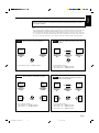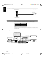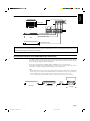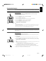
1
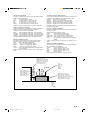
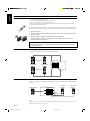
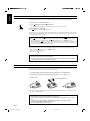
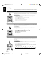
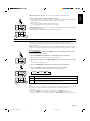
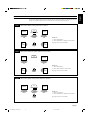
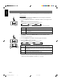
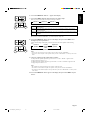
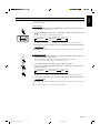
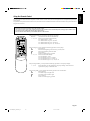
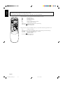
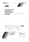
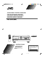
AUDIO/VIDEO CONTROL RECEIVER
AUDIO/VIDEO-RECEIVER MIT STEUEREINHEIT
AMPLI/TUNER DE COMMANDE AUDIO/VIDEO
GEINTEGREERDE AUDIO/VIDEO-VERSTERKER
RECEPTOR DE CONTROL DE AUDIO/VÍDEO
RICEVITORE DI CONTROLLO AUDIO/VIDEO
RX-430VBK
TV
/VIDEO
/I
TV
VCR
AUDIO
PRESET SEA MODE
CH+
1
CH–
TEST
4
CD
7/P
2
3
DELAY SURR MODE
5
6
–
+
REAR
8
TAPE
CD-DISC
FM/AM
AUDIO
CONTROL
VCR
TV
–
9
CENTER
10
MASTER VOLUME
+
+10
RX-430V
AUDIO/VIDEO CONTROL RECEIVER
TUNER/BAND
PRESET SEA
SOURCE
SURROUND
ADJUST
SETTING
SEA SURROUND
ON/OFF ON/OFF
–
TV CONTROL
+
– VOLUME +
ONE TOUCH
OPERATION
VIDEO
MEMORY
ONE TOUCH OPERATION
PHONO
–
VOLUME
+
MUTE
RM-SR430EU REMOTE CONTROL
STANDBY
POWER
PHONES
SPEAKERS
1
2
ENHANCED COMPULINK CONTROL SYSTEM
_ON —OFF
_ON —OFF
STANDBY/ON
INSTRUCTIONS
BEDIENUNGSANLEITUNG
MANUEL D’INSTRUCTIONS
GEBRUIKSAANWIJZING
MANUAL DE INSTRUCCIONES
ISTRUZIONI
For Customer Use:
Enter below the Model No. and Serial
No. which are located either on the rear,
bottom or side of the cabinet. Retain this
information for future reference.
Model No.
Serial No.
LET0022-001A
[EF, G]
RX-430VBK(EF)_0022-001A_Cover
1
97.4.24, 1:53 PM
Warnings, Cautions and Others/Warnung, Achtung und sonstige Hinweise/
Mises en garde, précautions et indications diverses/Waarschuwingen,
voorzorgen en andere mededelingen/Avisos, precauciones y otras notas/
Avvertenze e precauzioni da osservare
IMPORTANT for the U.K.
DO NOT cut off the mains plug from this equipment. If the plug
fitted is not suitable for the power points in your home or the cable
is too short to reach a power point, then obtain an appropriate
safety approved extension lead or consult your dealer.
BE SURE to replace the fuse only with an identical approved type,
as originally fitted.
If nonetheless the mains plug is cut off ensure to remove the fuse
and dispose of the plug immediately, to avoid a possible shock
hazard by inadvertent connection to the mains supply.
If this product is not supplied fitted with a mains plug then follow
the instructions given below:
IMPORTANT.
DO NOT make any connection to the terminal which is marked with
the letter E or by the safety earth symbol or coloured green or
green-and-yellow.
The wires in the mains lead on this product are coloured in
accordance with the following code:
Blue :
Neutral
Brown : Live
As these colours may not correspond with the coloured markings
identifying the terminals in your plug proceed as follows:
The wire which is coloured blue must be connected to the terminal
which is marked with the letter N or coloured black.
The wire which is coloured brown must be connected to the
terminal which is marked with the letter L or coloured red.
IF IN DOUBT - CONSULT A COMPETENT ELECTRICIAN.
Per I’ltalia:
“Si dichiara che il questo prodotto di marca JVC è conforme
alle prescrizioni del Decreto Ministeriale n.548 del 28/08/95
pubblicato sulla Gazzetta Ufficiale della Repubblica Italiana
n.301 del 28/12/95.”
G-1
RX-430VBK(EF)_0022-001A_G-Page
1
97.4.24, 1:59 PM
English
ACHTUNG
Zur Verhinderung von elektrischen Schlägen, Brandgefahr, usw:
1. Keine Schrauben lösen oder Abdeckungen enternen und nicht
das Gehäuse öffnen.
2. Dieses Gerät weder Regen noch Feuchtigkeit aussetzen.
PRECAUCIÓN
Para reducir riesgos de choques eléctricos, incendio, etc.:
1. No extraiga los tornillos, los cubiertas ni la caja.
2. No exponga este aparato a la lluvia o a la humedad.
ATTENTION
Afin d’éviter tout risque d’électrocution, d’incendie, etc.:
1. Ne pas enlever les vis ni les panneaux et ne pas ouvrir le coffret
de l’appareil.
2. Ne pas exposer l’appareil à la pluie ni à l’humidité.
ATTENZIONE
Per ridurre il rischio di scosse elettriche, incendi, ecc...
1. Non togliere viti, coperchi o la scatola.
2. Non esporre l’apparecchio alla piogggia e all’umidità.
Deutsch
VOORZICHTIG
Ter vermindering van gevaar voor brand, elektrische schokken, enz.:
1. Verwijder geen schroeven, panelen of de behuizing.
2. Stel dit toestel niet bloot aan regen of vocht.
Italiano
Español
Nederlands
Français
CAUTION
To reduce the risk of electrical shocks, fire, etc.:
1. Do not remove screws, covers or cabinet.
2. Do not expose this appliance to rain or moisture.
G-2
RX-430VBK(EF)_0022-001A_G-Page
2
97.4.24, 1:59 PM
Caution ––
POWER switch and STANDBY/ON
button!
POWER switch to be able to
This apparatus is provided with a
minimize power consumption for safe use. Therefore,
1. When doing initial setting, complete all the connections required,
connect the mains plug into the wall outlet, and set the POWER
switch to ON. After these, it will be available to operate STANDBY/
ON
button and so on.
2. When not in use, set the
POWER switch to OFF.
3. Disconnect the mains plug to shut the power off completely. The
POWER switch and STANDBY/ON
button in any position
do not disconnect the mains line.
4. The power can be remote controlled.
Achtung ––
POWER-Schalter und STANDBY/ON
-Taste!
Dieses Gerät hat einen Netzschalter ( POWER), um den
Stromverbrauch für sichere Verwendung auf ein Minimum bringen zu
können. Verfahren Sie deshalb wie folgt:
1. Beim ursprünglichen Aufbau alle erforderlichen Anschlüsse
herstellen, den Netzstecker in eine Wandsteckdose stecken, und
den
POWER-Schalter einschalten. Anschließend ist Betrieb
der STANDBY/ON
-Taste usw. möglich.
POWER-Schalter
2. Wenn das Gerät nicht verwendet wird, den
ausschalten.
3. Den Netzstecker aus der Steckdose ziehen, um die
Stromversorgung vollkommen zu unterbrechen. Der POWER-Taste unterbrechen in keiner
Schalter und die STANDBY/ON
Stellung die Stromversorgung vollkommen.
4. Die Stromversorgung kann mit der Fernbedienung ein- und
ausgeschaltet werden.
Attention — Commutateur POWER et d’une touche STANDBY/
ON
!
Cet appareil est équipé d’un commutateur POWER qui lui permet de
réduire sa consommation d’électricité pour une utilisation plus sûre.
Par conséquent,
1. En procédant au réglage initial, compléter toutes les connexions
nécessaires, connecter la fiche secteur dans la prise murale et
mettre le commutateur POWER sur la position ON. Ensuite, il
sera possible de contrôler la touche STANDBY/ON
, etc.
2. Mettre le commutateur
POWER sur la position OFF lorsque
l’appareil n’est pas utilisé.
3. Déconnecter la fiche secteur pour couper complètement le courant.
Le commutateur
POWER et la touche STANDBY/ON
ne
coupent jamais complètement l’alimentation, quelle que soit leurs
positions.
4. L’alimentation peut être télécommandée.
Voorzichtig ––
POWER en STANDBY/ON
schakelaars!
Dit apparaat is voorzien van een
POWER hoofdschakelaar om het
apparaat gebruiksklaar te zetten, maar te zorgen dat het stroomverbruik
minimaal blijft. Neem in verband hiermee het volgende in acht:
1. Bij de eerste ingebruikneming zorgt u eerst dat alle aansluitingen
in orde zijn, dan steekt u de stekker in het stopkontakt en dan zet
u de
POWER schakelaar in de “ON” stand. Daarna kunt u het
apparaat aan- en uitschakelen met de STANDBY/ON
schakelaar.
2. Wanneer u het apparaat geruime tijd niet gebruikt, kunt u beter de
POWER schakelaar in de “OFF” stand zetten.
3. Om de stroomtoevoer geheel uit te schakelen, trekt u de stekker
uit het stopkontakt. Anders zal er altijd een geringe hoeveelheid
stroom naar het apparaat lopen, ongeacht de stand van de
STANDBY/ON
en de POWER.
4. U kunt het apparaat ook met de afstandsbediening aan- en
uitschakelen.
Precaución –– Interruptor
POWER y botón STANDBY/ON
!
Esta unidad dispone de un interruptor
POWER que sirve para
reducir al mínimo el consumo de alimentación para proporcionar
mayor seguridad operacional. Por lo tanto,
1. Al ejecutar el ajuste inicial, después de completar todas las
conexiones requeridas, conectar el cable de alimentación a una
toma de pared, y activar el interruptor POWER. Entonces, será
posible ejecutar operaciones tales como la conmutación del
estado de alimentación.
2. Desactivar el interruptor
POWER al dejar la unidad fuera de
uso.
3. Desconectar el cable de alimentación para desactivar la
alimentación totalmente. Cualquier que sea la posición de ajustes
del interruptor
POWER y el botón STANDBY/ON
, la
alimentación no es cortada completamente.
4. La alimentación puede ser controlada remotamente.
Attenzione –– Interruttore
POWER e tasto STANDBY/ON
!
Per ridurre al minimo l’assorbimento di corrente ai fini della sicurezza,
questo apparecchio è stato dodato di un interruttore
POWER. Di
conseguenza,
1. Al momento dell’impostazione iniziale, completare tutti i
collegamenti richiesti, inserire la spina del cavo di alimentazione
nella presa a muro della rete elettrica e impostare l’interruttore
POWER in posizione ON. Fatto ciò, sarà pronto all’uso
STANDBY/ON
.
2. Quando non in uso, impostare l’interruttore POWER in posizione
OFF.
3. Disinserire la spina del cavo di alimentazione dalla presa della rete
elettrica per staccare completamente l’alimentazione. L’ interruttore
POWER e il tasto STANDBY/ON
in nessuna posizione
staccano la linea di alimentazione elettrica principale.
4. È possibile il controllo remoto dell’alimentazione.
G-3
RX-430VBK(EF)_0022-001A_G-Page
3
97.4.24, 1:59 PM
Caution: Proper Ventilation
To avoide risk of electric shock and fire and to protect from damage.
Locate the apparatus as follows:
Front:
No obstructions open spacing.
Sides:
No obstructions in 10 cm from the sides.
Top:
No obstructions in 10 cm from the top.
Back:
No obstructions in 15 cm from the back
Bottom:
No obstructions, place on the level surface.
In addition, maintain the best possible air circulation as illustrated.
Achtung: Angemessene Ventilation
Stellen Sie das Gerät zur Verhütung von elektrischem Schlag und
Feuer und zum Schutz gegen Beschädigung wie folgt auf:
Vorderseite: Offener Platz ohne Hindernisse.
Seiten:
Keine Hindernisse innerhalb 10 cm von den Seiten.
Oberseite: Keine Hindernisse innerhalb 10 cm von der Oberseite.
Rückseite: Keine Hindernisse innerhalb 15 cm von der Rückseite.
Unterseite: Keine Hindernisse. Auf eine ebene Oberfläche stellen.
Zusätzlich die bestmögliche Luftzirkulation wie gezeigt erhalten.
Attention: Ventilation Correcte
Pour éviter les chocs électriques, l’incendie et tout autre dégât.
Disposer l’appareil en tenant compte des impératifs suivants
Avant:
Rien ne doit gêner le dégagement
Flancs:
Laisser 10 cm de dégagement latéral
Dessus:
Laisser 10 cm de dégagement supérieur
Arrière:
Laisser 15 cm de dégagement arrière
Dessous:
Rien ne doit obstruer par dessous; poser l’appareil sur
une surface plate.
Veiller également à ce que l’air circule le mieux possible comme
illustré.
Voorzichtig: Zorg Voor Goede Ventilatie
Om gevaar voor brand of een elektrische schok te voorkomen, dient u
bij opstelling van het apparaat op de volgende punten te letten:
Voorkant:
Voldoende ruimte vrij houden.
Zijkanten:
Minstens 10 cm aan weerszijden vrij houden.
Bovenkant: Niets bovenop plaatsen; 10 cm speling geven.
Achterkant: Minstens 15 cm ruimte achteraan vrij houden.
Onderkant: Opstellen op een egaal horizontaal oppervlak.
Bovendien moet er rondom voldoende luchtdoorstroming zijn, zoals in
de afbeelding aangegeven.
Precaución: Ventilación Adecuada
Para evitar el riesgo de choque eléctrico e incendio y para proteger el
aparato contra daños.
Ubique el aparato de la siguiente manera:
Frente:
Espacio abierto sin obstrucciones
Lados:
10 cm sin obstrucciones a los lados
Parte superior: 10 cm sin obstrucciones en la parte superior
Parte trasera: 15 cm sin obstrucciones en la parte trasera
Fondo:
Sin obstrucciones, colóquelo sobre una superficie
nivelada
Además, mantenga la mejor circulación de aire posible como se
ilustra.
Attenzione: Problemi di Ventilazione
Per evitare il rischio di folgorazioni ed incendi e proteggere l’unità da
danni, installarla nel modo seguente.
Davanti:
Nessun ostacolo, spazio libero
Lati:
Nessun ostacolo per almeno 10 cm
Sopra:
Nessun ostacolo per almeno 10 cm
Retro:
Nessun ostacolo per almeno 15 cm
Fondo:
Libero ed in piano
Inoltre, mantenere il più possibile la circolazione dell’aria.
Spacing 15 cm or more
Abstand von 15 cm oder mehr
Dégagement de 15 cm ou plus
Minstens 15 cm tussenruimte
Espacio de 15 cm o más
15 cm di distanza o più
Front
Vorderseite
Avant
Voorkant
Frente
Davanti
RX-430VBK
Wall or obstructions
Wand oder Hindernisse
Mur, ou obstruction
Wand of meubilair
Pared u obstrucciones
Parete o ostacol
Stand height 15 cm or more
Standhöhe 15 cm oder mehr
Hauteur du socle: 15 cm ou plus
Standard op minstens 15 cm van de vloer
Allura del soporte 15 cm o más
Altezza del tavolino 15 cm p plù
Floor
Boden
Plancher
Vloer
Piso
Pavimento
G-4
RX-430VBK(EF)_0022-001A_G-Page
4
97.4.24, 1:59 PM
English
Table of Contents
Switches, Buttons and Controls ................................................................................................ 2
Getting Started ........................................................................................................................... 3
Before Installation .................................................................................................................... 3
Checking the Supplied Accessories ......................................................................................... 3
Connecting the FM and AM (MW/LW) Antennas .................................................................. 4
Connecting the Speakers .......................................................................................................... 5
Connecting Audio/Video Components .................................................................................... 7
Connecting Audio Components for the COMPU LINK-3 Remote Control System ............... 8
Connecting the Power Cord ..................................................................................................... 9
Putting Batteries in the Remote Control .................................................................................. 9
Basic Operations ...................................................................................................................... 10
Turning the Power On and Off (Standby) .............................................................................. 10
Selecting the Source to Play ................................................................................................... 10
Selecting the Front Speakers .................................................................................................. 11
Adjusting the Volume ............................................................................................................ 11
Muting the Sound ................................................................................................................... 11
Recording a Source ................................................................................................................ 12
Listening with Headphones .................................................................................................... 12
Basic Settings ........................................................................................................................... 13
Adjusting the Front Speaker Output Balance ........................................................................ 13
Listening at Low Volume (Loudness) ................................................................................... 13
Using the Sleep Timer ............................................................................................................ 13
Selecting the Center Speaker Size ......................................................................................... 14
One Touch Operation .............................................................................................................. 15
About the One Touch Operation ............................................................................................ 15
Using the One Touch Operation ............................................................................................ 15
Receiving Radio Broadcasts ................................................................................................... 16
Tuning in Stations Manually .................................................................................................. 16
Using Preset Tuning ............................................................................................................... 16
Selecting the FM Reception Mode ......................................................................................... 17
Using the Preset SEA Modes .................................................................................................. 18
Selecting Your Favorite SEA Mode ...................................................................................... 18
Using the Surround Processor ................................................................................................ 20
Using JVC’s Hall Surround ................................................................................................... 20
Speaker Arrangement for Dolby Surround ............................................................................ 22
Preparing for Dolby Surround ................................................................................................ 23
Using Dolby Surround ........................................................................................................... 26
COMPU LINK Remote Control System ............................................................................... 27
Using the Remote Control ....................................................................................................... 28
Troubleshooting ....................................................................................................................... 30
Specifications ............................................................................................................................ 31
Page 1
RX-430VBK(EF)_0022-001A_En
1
97.4.24, 1:55 PM
English
Switches, Buttons and Controls
Become familiar with the buttons and controls on the receiver before use.
1
2
3
4
5
6
TUNER/BAND
PRESET SEA
7
8
9
p
MASTER VOLUME
RX-430V
AUDIO/VIDEO CONTROL RECEIVER
–
SOURCE
SURROUND
ADJUST
SETTING
+
MEMORY
ONE TOUCH OPERATION
STANDBY
POWER
PHONES
SPEAKERS
1
2
ENHANCED COMPULINK CONTROL SYSTEM
_ON —OFF
_ON —OFF
STANDBY/ON
q
w
e
t
r
y
Refer to the pages in parentheses for details.
u
i
o
;
a
TV
/VIDEO
/I
TV
VCR
AUDIO
d
PRESET SEA MODE
CH+
1
CH–
TEST
4
CD
7/P
2
3
DELAY SURR MODE
5
6
–
TAPE
CD-DISC
FM/AM
AUDIO
CONTROL
VCR
TV
f
+
REAR
8
–
9
CENTER
10
+
+10
SEA SURROUND
ON/OFF ON/OFF
TV CONTROL
– VOLUME +
g
h
j
ONE TOUCH
OPERATION
VIDEO
k
l
PHONO
–
s
VOLUME
+
MUTE
RM-SR430EU REMOTE CONTROL
/
Front Panel
1 Remote sensor
2 Display (10)
3 MASTER VOLUME control (11)
4 MEMORY button (16)
5 TUNER/BAND button and lamp
(16, 17)
6 PRESET SEA button and lamp (18)
7 SOURCE button and lamp (10)
8 SURROUND button and lamp
(20, 23, 26)
9 ADJUST button and lamp (21, 23)
p SETTING button and lamp (13)
button and
q STANDBY/ON
STANDBY lamp (10)
w
POWER switch (9)
e PHONES jack (12)
r SPEAKERS 1/2 buttons (11)
t Control % / fi / @ / # buttons
y ONE TOUCH OPERATION button
and lamp (15)
Remote Control
u TV/VIDEO button (29)
i CH (+/–) buttons (29)
o CD-DISC button (28)
; AUDIO CONTROL button
(19, 21, 25, 26)
a Source buttons (CD, TAPE, FM/
AM, VCR, VIDEO, PHONO)
(10, 28, 29)
s VOLUME (+/–) buttons (11)
d
(Standby/On) buttons (TV,
VCR, AUDIO) (10, 29)
f 10 keys/Audio control buttons
(17, 19, 21, 25, 26, 28)
g SEA ON/OFF button (19)
h SURROUND ON/OFF button
(21, 25, 26)
j TV CONTROL buttons (TV,
VOLUME (+/–)) (29)
k ONE TOUCH OPERATION
button (15)
l Operating buttons for JVC audio/
video components (28, 29)
/ MUTE button (11)
Page 2
RX-430VBK(EF)_0022-001A_En
2
97.4.24, 1:55 PM
English
Getting Started
This section explains how to connect stereo components and speakers to the receiver, and how to connect the
power supply.
Before Installation
General
• Be sure your hands are dry.
• Turn the power off to all components.
• Read the manuals supplied with the components you are going to connect.
Locations
• Install the receiver in a location that is level and protected from moisture.
• The temperature around the receiver must be between –5˚ and 35˚ C (23˚ and 95˚ F).
• Make sure there is good ventilation around the receiver. Poor ventilation could cause overheating and
damage the receiver.
Handling the receiver
• Do not insert any metal object into the receiver.
• Do not disassemble the receiver or remove screws, covers, or cabinet.
• Do not expose the receiver to rain or moisture.
Checking the Supplied Accessories
Check to be sure you have all of the following items, which are supplied with the receiver.
The number in the parentheses indicates quantity of the pieces supplied.
• Remote Control (1)
• Batteries (2)
• AM (MW/LW) Loop Antenna (1)
• FM Antenna (1)
If anything is missing, contact your dealer immediately.
Page 3
RX-430VBK(EF)_0022-001A_En
3
97.4.24, 1:55 PM
English
Connecting the FM and AM (MW/LW) Antennas
FM Antenna Connections
A
B
A
NN
TE
AN
75
FMAXIAL
D
GN
GN
CO
CO
D
AM
T
EX
AMP
O
LO
A
NN
TE
AN
75
FMAXIAL
AMP
O
LO
AM
T
EX
Note: Make sure the antenna conductors do not touch any
other terminals, connecting cords or power cord. This
could cause poor reception.
Extend the supplied FM antenna horizontally.
FM Antenna
ANTENNA
A Using the Supplied FM Antenna
The FM antenna provided can be connected to the FM 75ohm COAXIAL terminal as temporary measure.
B Using the Standard Type Connector (Not Supplied)
A standard type connector (IEC or DIN45325) should be
connected to the FM 75-ohm COAXIAL terminal.
FM 75
COAXIAL
If reception is poor, connect an outdoor FM
antenna.
GND
Outdoor FM Antenna
AM
LOOP
AM
EXT
Before attaching a 75-ohm coaxial cable (the
kind with a round wire going to the outdoor FM
antenna), disconnect the supplied FM antenna.
AM (MW/LW) Antenna Connections
ANTENNA
Turn the loop until you have the best reception.
FM 75
COAXIAL
AM (MW/LW) Loop Antenna
GND
AM
LOOP
AM
EXT
1
Snap the tabs on the loop into the slots of the
base to assemble the AM (MW/LW) loop.
2
3
AM (MW/LW) Wire Antenna
If reception is poor, connect an outdoor single vinylcovered wire to the AM EXT terminal. (Keep the AM
(MW/LW) loop antenna connected.)
Note :
Make sure the antenna conductors do not touch any other terminals, connecting cords and power cord. This
could cause poor reception.
Page 4
RX-430VBK(EF)_0022-001A_En
4
97.4.24, 1:55 PM
English
Connecting the Speakers
You can connect the following speakers:
• Two sets of front speakers to produce normal stereo sound
• One set of rear speakers to enjoy the surround effect
• One center speaker to produce more effective surround effect (to make human voices outstanding)
• One subwoofer to enhance the bass
For each speaker (except for subwoofer), connect one end of the speaker signal cable (not supplied) to the
speaker terminal on the rear panel and the other end to the speaker. (For connecting a subwoofer, see page 7).
1. Open each terminal.
2. Insert the end of the speaker signal cable as shown (be sure to remove the insulation at the end
of each wire first).
3. Close the terminals to clamp the speaker signal cables firmly in place.
4. Connect the black (–) and red (+) terminals on the rear panel to the black (–) and red (+)
terminals marked on the speakers.
CAUTION:
When connecting speakers, use speakers with the same SPEAKER IMPEDANCE indicated by
the speaker terminals.
Connecting the front speakers
Connect the front speakers to the FRONT SPEAKERS terminals.
SPEAKERS 1
FRONT SPEAKERS
RIGHT
Left Speaker
Right Speaker
LEFT
1
1
2
2
SPEAKERS 2
Connecting the rear and center speakers
Connect rear speakers to the REAR SPEAKERS terminals and a center speaker to the CENTER SPEAKER
terminals.
Center Speaker
CENTER
SPEAKER
Left Rear
Speaker
RIGHT
LEFT
Right Rear
Speaker
REAR
SPEAKERS
Note:
When you connect rear speakers, make sure that both left and right speakers are connected; otherwise, no
sound will come out of the rear speakers.
Page 5
RX-430VBK(EF)_0022-001A_En
5
97.4.24, 1:55 PM
CAUTION:
When connecting speakers, use speakers with the same SPEAKER IMPEDANCE indicated by
the speaker terminals.
Notes:
• The required speaker impedance of the front speakers does not differ depending on whether both the
FRONT SPEAKERS 1 and FRONT SPEAKERS 2 terminals are used or only one of them is used.
• The required speaker impedance of the front speakers differs depending on whether or not a center and/
or rear speakers are connected at the same time. Since there are four possible speaker connections with
the receiver, check which one fits your case and use the speaker with the impedance described below.
CASE 1
When you connect only front speakers
Front
Speaker
Front
Speaker
CASE 2
When you connect front speakers and a center
speaker
Front
Speaker
Front
Speaker
Center Speaker
Use front speakers with 4 — 16 ohm impedance.
Use the following speakers;
• Front speakers: 8 — 16 ohm impedance
• Center speaker: 8 — 16 ohm impedance
CASE 3
CASE 4
When you connect front and rear speakers
Front
Speaker
Front
Speaker
When you connect front and rear speakers as
well as a center speaker
Front
Speaker
Front
Speaker
Center Speaker
Rear
Speaker
Rear
Speaker
Use the following speakers;
• Front speakers: 8 — 16 ohm impedance
• Rear speakers: 8 — 16 ohm impedance
Rear
Speaker
Rear
Speaker
Use the following speakers;
• Front speakers: 8 — 16 ohm impedance
• Rear speakers: 8 — 16 ohm impedance
• Center speaker: 8 — 16 ohm impedance
Page 6
RX-430VBK(EF)_0022-001A_En
6
97.4.24, 1:55 PM
English
About the speaker impedance of the speakers
English
Connecting the subwoofer speaker
Connect the input jack of a powered subwoofer to the SUBWOOFER OUT jack on the rear panel, using a cable
with RCA pin plugs.
SUBWOOFER
OUT
Powered subwoofer
Connecting Audio/Video Components
You can connect the following components to the receiver using cables with RCA pin plugs.
Audio Components
Video Components
• Turntable
• CD player
• VCR
• Video disc player
• Cassette deck
• TV
Note:
Any turntables incorporating a small-output cartridge such as an MC (moving-coil type) must be connected
to the receiver through a commercial head amplifier or step-up transformer. Direct connection may result
in insufficient volume.
Audio component connections
If a ground cable is provided
for your turntable, connect
the cable to the GND
terminal of the AM LOOP
terminals on the rear panel.
To audio output
ANTENNA
MONITOR
OUT
CD player
FM 75
COAXIAL
VIDEO
OUT
(REC)
IN
(PLAY)
VCR
GND
Turntable
PHONO
CD
OUT
(REC)
AM
LOOP
IN
(PLAY)
VIDEO
To audio input
TAPE
OUT
(REC)
IN
(PLAY)
AM
EXT
LEFT
Turntable
AUDIO
To audio output
To audio
output
RIGHT
Page 7
RX-430VBK(EF)_0022-001A_En
7
97.4.24, 1:55 PM
Cassette deck
English
Video component connections
MONITOR
OUT
To video input
VIDEO
OUT
(REC)
IN
(PLAY)
VCR
PHONO
CD
VIDEO
TAPE
OUT
(REC)
IN
(PLAY)
OUT
(REC)
IN
(PLAY)
TV
LEFT
AUDIO
RIGHT
To audio/video input
VHS
VCR
To audio/video output
To audio/video output
Video disc player
CAUTION:
If you connect a sound-increasing device such as a graphic equalizer between the source components and the receiver, the
sound output through the receiver may be distorted.
Connecting Audio Components for the COMPU LINK-3 Remote Control System
The COMPU LINK-3 remote control system allows you to control other JVC audio components from the
receiver or vice versa. To use this system, connect your JVC audio components and the receiver with the cable
(monaural mini-plug) supplied with those components.
If your audio component has two COMPU LINK-3 SYNCHRO jacks, you can use either one.
If it has only one COMPU LINK-3 SYNCHRO jack, connect it so that it is the last item in the series of
components (for example, the turntable and the CD player in the diagram below).
Notes:
• The COMPU LINK-3 remote control system is the upgraded version of the COMPU LINK-1 and COMPU
LINK-2. Even if your component has the COMPU LINK-1 or COMPU LINK-2 jacks, you can still connect
it in the COMPU LINK-3 remote control system, but some functions may not work correctly.
• For more information about the COMPU LINK-3 (-1 and -2) remote control system, see page 27.
COMPU LINK – 3
SYNCHRO
CD player
Cassette deck
Turntable
Page 8
RX-430VBK(EF)_0022-001A_En
8
97.4.24, 1:55 PM
English
Connecting the Power Cord
Before plugging the receiver into an AC outlet, make sure that all connections have been made.
1. Plug the power cord into an AC outlet.
2. Press POWER to set it in the _ON position.
The STANDBY lamp lights up. A small amount of power is always consumed.
POWER
_ON —OFF
To shut off the power completely:
Press POWER to set it in the —OFF position.
Keep the power cord away from the connecting cables for the TV, VCR, and antenna. The power cord may
cause noise or screen interference. We recommend that you use a coaxial cable to connect the antenna, since
it is well-shielded against interference.
The difference between the POWER switch and the STANDBY/ON
button
• The POWER switch is the mains supply switch, allowing the receiver to connect to the mains supply.
To shut off the power completely, press the POWER switch to set it in the —OFF position.
button is a functional on/off (standby) switch, and does not disconnect the
• The STANDBY/ON
receiver from the mains supply. A small amount of power is consumed even in standby mode for the
receiver to accept signals from the remote control.
Note:
The preset settings such as preset channel and sound adjustment may be erased in the following cases:
• When you press POWER to set it in the —OFF position.
• When you unplug the power cord.
• When a power failure occurs.
CAUTIONS:
• Do not touch the power cord with wet hands.
• Do not pull on the power cord to unplug the receiver. When unplugging the receiver, always
grasp the plug itself so as not to damage the cord.
Putting Batteries in the Remote Control
Before using the remote control, put the two supplied batteries in first. When using the remote control, aim
the remote control directly at the remote sensor on the receiver.
1. On the back of the remote control, press down on the battery cover and slide it out.
2. Insert batteries. Make sure to observe the proper polarity: (+) to (+) and (–) to (–).
3. Slide the cover.
R6P (SUM-3)/AA (15F)
If the range or effectiveness of the remote control decreases, replace the batteries. Use two R6P (SUM-3)/
AA (15F) type dry-cell batteries.
CAUTIONS:
Follow these precautions to avoid leaking or cracking cells:
• Place batteries in the remote control so they match the polarity indicated: (+) to (+) and (–)
to (–).
• Use the correct type of batteries. Batteries that look similar may differ in voltage.
• Always replace both batteries at the same time.
• Do not expose batteries to heat or flame.
Page 9
RX-430VBK(EF)_0022-001A_En
9
97.4.24, 1:56 PM
English
Basic Operations
The following operations are commonly used when you play any sound source.
Turning the Power On and Off (Standby)
On the front panel:
.
To turn on the power, press STANDBY/ON
The STANDBY lamp goes off. The name of the current source (or station frequency) appears on the display.
STANDBY
STANDBY/ON
MUTE TUNED
SLEEP SEA
AUTO STEREO PRO LOGIC 3CH LOGIC HALL
VOLUME
MHz
kHz
CH-
Current source name appears
STANDBY
R
L
LOUDNESS
Current volume level is shown here
To turn off the power (into standby mode), press STANDBY/ON
The STANDBY lamp lights up.
STANDBY/ON
again.
From the remote control:
To turn on the power, press AUDIO.
The STANDBY lamp goes off. The name of the current source (or station frequency) appears on the display.
AUDIO
To turn off the power (into standby mode), press AUDIO again.
The STANDBY lamp lights up.
Note:
Pressing STANDBY/ON
again turns off the power (into standby mode) and lights the STANDBY lamp.
A small amount of power is consumed in standby mode. To turn the power off completely, press
POWER
to set it in the —OFF position on the front panel.
Selecting the Source to Play
On the front panel:
SOURCE
1. Press SOURCE so that Control % / fi buttons work for selecting the source.
The lamp above the button lights up.
2. Press Control % / fi until the source name you want appears on the display.
VOLUME
From the remote control:
CD
Press one of the source button directly.
TAPE
CD*
TAPE*
FM/AM*
VCR
VIDEO
PHONO*
FM/AM
VCR
Listen to the CD player.
Listen to the cassette deck connected to the TAPE jacks.
Listen to an FM or AM (MW/LW) broadcast.
View the video component connected to the VCR jacks.
View the video component connected to the VIDEO jacks.
Listen to a record.
VIDEO
Note:
* When you press one of the source buttons on the remote control marked above with an asterisk, the receiver
automatically turns on.
PHONO
Page 10
RX-430VBK(EF)_0022-001A_En
10
97.4.24, 1:56 PM
English
Selecting the Front Speakers
When you have connected two sets of front speakers, you can select which to use. Pressing SPEAKERS 1 or
SPEAKERS 2 activates the respective set of speakers.
To use the set of speakers connected to the FRONT SPEAKERS 1 terminals, press SPEAKERS 1 to set
it in the _ON position, and press SPEAKERS 2 to set it in the —OFF position.
To use the set of speakers connected to the FRONT SPEAKERS 2 terminals, press SPEAKERS 2 to set
it in the _ON position, and press SPEAKERS 1 to set it in the —OFF position.
To use both sets of speakers, press both SPEAKERS 1 and 2 to set them in the _ON position.
To use neither set of speakers, press both SPEAKERS 1 and 2 to set them in the —OFF position.
SPEAKERS
1
2
_ON —OFF
Note:
When only one set of the front speakers is connected to either the FRONT SPEAKERS 1 or 2 terminals, do
not press both SPEAKERS 1 and 2 to set them in the _ON position. If you do, no sound comes out of the front
speakers.
Adjusting the Volume
MASTER VOLUME
On the front panel:
–
To increase the volume, turn MASTER VOLUME clockwise.
To decrease the volume, turn it counterclockwise.
+
When you turn MASTER VOLUME rapidly, the volume level also changes rapidly.
When you turn MASTER VOLUME slowly, the volume level also changes slowly.
On the front panel
–
VOLUME
From the remote control:
To increase the volume, press VOLUME +.
To decrease the volume, press VOLUME –.
+
From the remote control
CAUTION:
Always set the volume to the minimum before starting any source. If the volume is set at its high
level, the sudden blast of sound energy can permanently damage your hearing and/or ruin your
speakers.
Muting the Sound
From the remote control only:
Press MUTE to mute the sound through all speakers and headphones connected.
“MUTE” appears on the display and the volume turns off.
MUTE
To restore the sound, press MUTE again so that “OFF” appears on the display.
Turn MASTER VOLUME or pressing VOLUME +/– also restores the sound at the previous volume level.
Page 11
RX-430VBK(EF)_0022-001A_En
11
97.4.24, 1:56 PM
You can record any source playing through the receiver to a cassette deck connected to the TAPE jacks
and VCR connected to the VCR jacks at the same time.
While recording, you can listen to the selected sound source at whatever sound level you like, without
affecting the sound levels of the recording.
Note:
The output volume level, preset SEA, and surround modes cannot affect the recording.
Listening with Headphones
A standard pair of headphones can be connected to the PHONES jack on the front panel. Be sure to turn down
the volume before connecting or putting on headphones, as high volume can damage both the
headphones and your hearing.
SPEAKERS
1
To listen with only headphones
Press both SPEAKERS 1 and 2 to set them in the —OFF position.
2
_ON —OFF
Page 12
RX-430VBK(EF)_0022-001A_En
12
97.4.24, 1:56 PM
English
Recording a Source
English
Basic Settings
Some of the following settings are required after connecting and positioning your speakers in your listening
room, while others will make operations easier.
Adjusting the Front Speaker Output Balance
SETTING
If the sounds you hear from the front right and left speakers are unequal, you can adjust the speaker output
balance.
On the front panel only:
1. Press SETTING so that the Control % / fi / @ / # buttons work for adjusting the balance.
The lamp above the button lights up.
2. Press Control % / fi until “BALANCE” appears on the display.
3. Press Control @ / # to adjust the balance.
• Pressing Control @ decreases the right channel output.
• Pressing Control # decreases the left channel output.
Listening at Low Volume (Loudness)
Human ears are not sensitive to bass at low volume. To compensate for this, the loudness function
automatically boosts the bass level as you lower the volume.
SETTING
On the front panel only:
1. Press SETTING so that the Control % / fi / @ / # buttons work for setting the loudness.
The lamp above the button lights up.
2. Press Control % / fi until “LOUDNESS” appears on the display.
3. Press Control @ / # to set the loudness function to “ON” or “OFF.”
• Select “ON” to activate the loudness function.
The LOUDNESS indicator lights up on the display.
• Select “OFF” to cancel it.
The indicator goes off.
Using the Sleep Timer
Using the Sleep Timer, you can fall asleep to music and know the receiver will turn off by itself rather than
play all night.
On the front panel only:
SETTING
1. Press SETTING so that the Control % / fi / @ / # buttons work for setting the Sleep Timer.
The lamp above the button lights up.
2. Press Control % / fi until “<SLEEP>” appears on the display.
3. Press Control @ / # to set the shut-off time.
Each time you press the button, the shut-off time on the display changes as follows, and the SLEEP
indicator lights up on the display.
10
20
30
40
50
60
0
(Canceled)
Page 13
RX-430VBK(EF)_0022-001A_En
13
97.4.24, 1:56 PM
70
80
To check or change the time remaining until the shut-off time:
1. Press SETTING if necessary, so that the Control % / fi / @ / # buttons work for setting the Sleep Timer.
2. Press Control % / fi if necessary, until “<SLEEP>” appears on the display.
3. Press Control @ / #.
The remaining time until the shut-off time appears in minutes.
• To change the shut-off time, press Control @ / # repeatedly.
SETTING
To cancel the Sleep Timer, press Control @ / # repeatedly in step 3 above until “0” appears on the display.
(The SLEEP indicator goes off.)
Turning off the power (into standby mode) also cancels the Sleep Timer.
Selecting the Center Speaker Size
You can register the information about the center speaker after all connections are completed.
If you do this registration first, you do not have to adjust the center speaker mode when you want to activate
the surround sound.
However, to register the information, first you have to set the surround mode either to “PROLOGIC” or
“3CHLOGIC.” (You cannot select the center speaker size when the surround mode is “OFF” or “HALL.”)
On the front panel only:
1. Press SURROUND so that the Control % / fi buttons work for selecting the surround mode.
The lamp above the button lights up.
SURROUND
2. Press Control % / fi until “PROLOGIC” or “3CHLOGIC” appears on the display.
The indicator of the selected mode also lights up on the display.
3. Press SETTING so that the Control % / fi / @ / # buttons work for selecting the center speaker
size.
The lamp above the button lights up.
SETTING
4. Press Control % / fi until “CNTR SPK” (Center Speaker) appears on the display.
5. Press Control @ / # to select the appropriate item about your center speaker.
Each time you press the button, the display changes to show the following:
LARGE
SMALL
NO
LARGE Select this mode when the size of the center speaker is the same as that of the front speakers.
SMALL Select this mode when the size of the center speaker is smaller than that of the front speakers.
NO
Select this mode when you do not use a center speaker.
(This mode cannot be selected when you select “3CHLOGIC.”)
Note:
This “center speaker size” setting is so related to the center mode setting for the Dolby Surround that
changing this setting affects and changes the center mode to a relevant mode, and vice versa.
For example;
• If you select “LARGE,” the center mode is automatically set to “WIDE,” and vice versa.
• If you select “SMALL,” the center mode is automatically set to “NORMAL,” and vice versa.
• If you select “NO,” the center mode is automatically set to “PHANTOM” for PRO LOGIC, and vice versa.
Page 14
RX-430VBK(EF)_0022-001A_En
14
97.4.24, 1:56 PM
English
When the shut-off time comes, the receiver turns off (into standby mode) automatically.
English
One Touch Operation
This receiver can memorize the optimum sound setting for each playing source.
About the One Touch Operation
JVC’s One Touch Operation function is used to assign and store different sound settings for each different
playing source. By using this function, you do not have to change the settings every time you change the
source. The stored settings for the newly selected source are automatically recalled.
The following can be stored for each source:
• Volume level (see page 11)
• Balance (see page 13)
• Loudness (see page 13)
• Preset SEA modes (see page 18)
• Surround mode settings (see page 20)
Note:
If the source is FM or AM (MW/LW), the One Touch Operation function works only when preset channels
from 1 — 20 are turned in. You can assign a different setting for each preset channel.
Using the One Touch Operation
ONE TOUCH
OPERATION
ONE TOUCH OPERATION
On the front From the
remote control
panel
To store the sound settings:
1. Press ONE TOUCH OPERATION.
The ONE TOUCH OPERATION lamp lights up, then the previously memorized settings are recalled and
appear on the display in turn.
2. Adjust the sound using the functions listed above.
The newly adjusted settings are memorized.
To recall the sound settings:
With the ONE TOUCH OPERATION lamp lit, the settings for the currently selected source is recalled, and
appears on the display when the source is selected.
To cancel the One Touch Operation function:
Press ONE TOUCH OPERATION so that the lamp goes off. (Even though the One Touch Operation function
is canceled, the recalled sound effects remain active.)
Page 15
RX-430VBK(EF)_0022-001A_En
15
97.4.24, 1:56 PM
You can browse through all the stations or use the preset function to go immediately to a particular station.
Tuning in Stations Manually
On the front panel only:
TUNER/BAND
1. Press TUNER/BAND so that the Control % / fi / @ / # buttons work for tuner settings.
The indicator above the button lights up.
2. Press Control % / fi until “<FM AM>” appears on the display.
3. Press Control @ / # to select the band.
Each time you press the button, the band alternates between FM and AM (MW/LW).
4. Press Control % / fi until “–TUNING+” appears on the display.
5. Press Control @ / # until you find the frequency you want.
• Pressing Control @ decreases the frequency.
• Pressing Control # increases the frequency.
Notes:
• When you hold down Control @ / # in step 5, the frequency keeps changing until you press Control @ /
# again or a station is tuned in.
• When a station of sufficient signal strength is tuned in, the TUNED indicator lights up on the display.
• When an FM stereo program is received, the STEREO indicator also lights up.
Using Preset Tuning
Once a station is assigned to a channel number, the station can be quickly tuned. You can preset up to 40
stations at random.
Storing the preset stations
On the front panel only:
1. Tune in the station you want to preset (see above).
If you want to store the FM reception mode for this station, select the FM reception mode you want.
See page 17 for details.
2. Press MEMORY.
“CH-” appears and the channel number position starts flashing on the display for about 5 seconds.
MEMORY
3. Press Control @ / # to select a channel number while the channel number position is flashing.
• Pressing Control @ decreases the number.
• Pressing Control # increases the number.
Note:
You can press 10 keys on the remote control to select a channel number in this step if you have pressed
FM/AM prior to starting this preset procedures.
For channel number 5, press 5. For channel number 15, press +10 then 5.
For channel number 20, press +10 then 10. For channel number 30, press +10, +10 then 10.
4. Press MEMORY again while the selected channel number is flashing on the display.
The selected channel number stops flashing. The station is assigned to the selected channel number.
MEMORY
5. Repeat steps 1 to 4 until you store all the stations you want.
Page 16
RX-430VBK(EF)_0022-001A_En
16
97.4.24, 1:56 PM
English
Receiving Radio Broadcasts
English
To cancel a stored preset station
Storing a new station on a used number erases the previously stored one.
CAUTION:
The preset channels may be erased in the following cases:
• When you press POWER to set it in the —OFF position.
• When you unplug the power cord.
• When a power failure occurs.
Tuning in a Preset Station
On the front panel:
TUNER/BAND
1. Press TUNER/BAND so that the Control % / fi / @ / # buttons work for tuner settings.
The lamp above the button lights up.
2. Press Control % / fi until “–PRESET+” appears on the display.
3. Press Control @ / # to select a preset channel.
Each time you press the button, the preset channels change.
• Pressing Control @ changes preset channel in decreasing order.
• Pressing Control # changes preset channels in increasing order.
From the remote control:
FM/AM
1
TEST
4
1. Press FM/AM.
The last received station of the last selected band is tuned in.
Each time you press the button, the band alternates between FM and AM (MW/LW).
PRESET SEA MODE
2
2. Press 10 keys to select a preset channel number.
For channel number 5, press 5. For channel number 15, press +10 then 5.
For channel number 20, press +10 then 10. For channel number 30, press +10, +10 then 10.
3
DELAY SURR MODE
5
6
–
7/P
+
REAR
8
–
9
CENTER
10
+
+10
Selecting the FM Reception Mode
You can change the FM reception mode while receiving an FM broadcast.
TUNER/BAND
On the front panel only:
1. Press TUNER/BAND so that the Control % / fi / @ / # buttons work for tuner settings.
The lamp above the button lights up.
2. Press Control % / fi until “FM MODE” appears on the display.
3. Press Control @ / # to select either “FM AUTO” or “FM MONO.”
• Normally select “FM AUTO.”
• When an FM stereo broadcast is hard to receive or noisy, select “FM MONO.”
FM AUTO
FM MONO
When a program is broadcast in stereo, you will hear stereo sound; when in monaural,
you will hear monaural sounds. This mode is also useful to suppress static noise between
stations.
The MUTE AUTO indicator lights up on the display.
Reception will be improved although you will lose the stereo effect.
In this mode, you will hear noise while tuning into the stations.
The MUTE AUTO indicator goes off on the display.
Note:
You can store the FM reception mode for each preset station.
Page 17
RX-430VBK(EF)_0022-001A_En
17
97.4.24, 1:56 PM
The preset SEA (Sound Effect Amplifier) modes give you control over the way your music sounds.
Note:
The preset SEA mode cannot be used for recording.
Selecting Your Favorite SEA Mode
On the front panel:
1. Press PRESET SEA so that the Control % / fi / @ / # buttons work for preset SEA setting.
The lamp above the button lights up.
PRESET SEA
2. Press Control % / fi until the mode you want appears on the display.
The SEA indicator also lights up on the display.
Each time you press the button, the preset SEA modes change as follows:
MOVIE
SPORTS
MUSIC
OFF
Note:
When you turn on the preset SEA mode, the mode and its effect level previously selected is recalled at first.
3. Press Control @ / # to select the effect level.
Each time you press the button, the effect level changes as follows:
When “MOVIE” is selected:
MOVIE 1
MOVIE 2
MOVIE 3
When “SPORTS” is selected:
SPORTS1
SPORTS2
SPORTS3
When “MUSIC” is selected:
JAZZ 1
COUNTRY2
JAZZ 2
ROCK 1
ROCK 2
COUNTRY1
MUSICAL2
MUSICAL1
MOVIE
Adds breadth to sounds so you feel like you are in a movie theater.
SPORTS
Makes sound exciting.
MUSIC
Select one of the modes below:
JAZZ:
Gives a feeling of a live atmosphere. Good for acoustic music.
ROCK:
Gives a heavy sound. Both high and low frequencies are boosted.
MUSICAL: Enhances the mid-frequency range, which the human voice is mostly
made up of.
COUNTRY: Enhance the high-frequency range so that instruments such the violin
and banjo are emphasized.
OFF
No preset SEA mode is applied. (See below)
To cancel the preset SEA mode, select “OFF” in step 2 above.
The SEA indicator goes off from the display.
Page 18
RX-430VBK(EF)_0022-001A_En
18
97.4.24, 1:56 PM
English
Using the Preset SEA Modes
English
From the remote control:
SEA
ON/OFF
1. Press SEA ON/OFF so that the SEA indicator lights up on the display.
The previously selected mode is recalled (at its previous effect level) and is shown on the display.
Each time you press the button, the preset SEA mode turns on and off.
Note:
When selecting the preset SEA mode, the display will show the current effect level of the preset SEA mode
selected.
AUDIO
CONTROL
2. Press AUDIO CONTROL so that 10 keys work for adjusting the sound.
3. Press SEA MODE until the mode you want appears on the display.
Each time you press the button, the three preset SEA modes change as follows:
SEA MODE
3
Ex.
MOVIE 1
SPORTS2
JAZZ 2
4. Press PRESET to select the effect level.
Each time you press the button, the effect level changes as follows:
PRESET
2
When “MOVIE” is selected:
MOVIE 1
MOVIE 2
MOVIE 3
When “SPORTS” is selected:
SPORTS1
SPORTS2
SPORTS3
When “MUSIC” is selected:
JAZZ 1
COUNTRY2
JAZZ 2
ROCK 1
ROCK 2
COUNTRY1
MUSICAL2
MUSICAL1
To cancel the preset SEA mode, press SEA ON/OFF so that the SEA indicator goes off from the
display.
Each time you press the button, the preset SEA mode turns on and off.
Page 19
RX-430VBK(EF)_0022-001A_En
19
97.4.24, 1:56 PM
The built-in surround processor provides three types of surround programs — Dolby Pro Logic, Dolby 3Channel Logic, and JVC’s Hall Surround.
What is surround?
The sound heard in a concert hall or a movie theater consists of direct sound and indirect sound: early
reflections and reflections from behind. The reflected sounds are always delayed by the distances of the ceiling
and walls from the listener. These reflections are some of the most important elements of the acoustic
surround.
On JVC’s Hall Surround
Early reflections
In order to reproduce a more realistic sound field in your listening
room while playing an ordinary stereo source, JVC’s Hall Surround
has been designed to give you clear vocals and to create the
feeling of a concert hall. The sound is reproduced through the
front speakers and rear speakers.
Reflections
from behind
On Dolby Surround
Dolby Surround has been also developed to reproduce the
important elements of the acoustic surround at home.
To watch the soundtracks of video software bearing the mark
DOLBY SURROUND * which includes the same encoded surround
information as found in Dolby Stereo films, the receiver can
provide you with 2 Dolby Surround programs (Dolby Pro Logic
and Dolby 3ch Logic).
Dolby Pro Logic: Select this mode when the optional rear
speakers are connected (as well as a center speaker).
Dolby 3ch Logic: Select this mode when a center speaker is
connected without rear speakers.
Direct sound
* Manufactured under license from Dolby Laboratories Licensing
Corporation. “Dolby,” the double-D symbol, and “Pro Logic” are
trademarks of Dolby Laboratories Licensing Corporation.
Notes:
• The surround processor has no effect on monaural sources.
• The surround processor cannot be used for recording.
Using JVC’s Hall Surround
You need to connect one set of rear speakers to obtain the full effect.
Once you have adjusted the Hall Surround, the receiver memorizes the settings.
On the front panel:
1. Press SURROUND so that the Control % / fi / @ / # buttons work for selecting the surround
modes.
The lamp above the button lights up.
SURROUND
2. Press Control % / fi until “HALL” appears on the display.
The HALL indicator also lights up on the display.
Each time you press the button, the surround modes change as follows:
PROLOGIC
3CHLOGIC
HALL
OFF
The indicator of the selected surround mode lights up in turn as you select the surround modes.
Page 20
RX-430VBK(EF)_0022-001A_En
20
97.4.24, 1:56 PM
English
Using the Surround Processor
3. Press ADJUST so that the Control % / fi / @ / # buttons work for surround settings.
The lamp above the button lights up.
English
ADJUST
4. Press Control % / fi until “– REAR +” appears on the display.
5. Press Control @ / # to adjust the rear speaker output level.
• Pressing Control @ decreases the output level up to –10 dB.
• Pressing Control # increases the output level up to +10 dB.
6. Press Control % / fi until “–DELAY +” appears on the display.
7. Press Control @ / # to adjust the delay time of the rear speaker output.
Each time you press the button, the delay time changes as follows:
DELAY 1
DELAY 2
DELAY 3
DELAY 1
Select this when the distance from you to your rear speakers is greater than that to the front
speakers.
DELAY 2
Select this when the distance from you to your rear speakers is almost equal to that to the
front speakers.
DELAY 3
Select this when the distance from you to your rear speakers is less than that to the front
speakers.
To cancel the Hall surround, select “OFF” in step 2. The HALL indicator goes off.
From the remote control:
SURROUND
ON/OFF
1. Press SURROUND ON/OFF so that one of the surround mode indicators (PRO LOGIC, 3CH
LOGIC, HALL) lights up on the display.
The previous mode is recalled (at its previous settings) and is shown on the display.
Each time you press the button, the surround mode turns on and off.
AUDIO
CONTROL
2. Press AUDIO CONTROL so that 10 keys work for adjusting the sound.
3. Press SURR MODE until “HALL” appears on the display.
The HALL indicator also lights up on the display.
Each time you press the button, the surround modes change as follows:
SURR MODE
6
PROLOGIC
3CHLOGIC
HALL
The indicator of the selected surround mode lights up in turn as you select the surround modes.
–
REAR
8
+
9
4. Press REAR +/– to adjust the rear speaker output level.
• Pressing REAR – decreases the output level up to –10 dB.
• Pressing REAR + increases the output level up to +10 dB.
5. Press DELAY to adjust the delay time.
Each time you press the button, the delay time changes as follows:
DELAY
5
DELAY 1
DELAY 2
DELAY 3
To cancel the Hall Surround, press SURROUND ON/OFF so that the HALL indicator goes off.
Each time you press the button, the surround mode turns on and off.
Page 21
RX-430VBK(EF)_0022-001A_En
21
97.4.24, 1:56 PM
The following illustrations show how to obtain the optimum sound environment for various Dolby Surround
settings. Try to find the speaker direction and location to create the optimum sound field.
CASE 1
When you have added a center speaker and rear speakers
Front
Speaker
TV
Front
Speaker
Center Speaker
In this case:
1. Select “PROLOGIC.”
2. Select “NORMAL” or “WIDE” for center mode.
Rear
Speaker
CASE 2
Rear
Speaker
See pages 23 to 25 for more details.
When you have added rear speakers (without a center speaker)
Front
Speaker
TV
Front
Speaker
In this case:
1. Select “PROLOGIC.”
2. Select “PHANTOM” for center mode.
Rear
Speaker
CASE 3
Rear
Speaker
See pages 23 to 25 for more details.
When you have added a center speaker (without rear speakers)
Front
Speaker
TV
Front
Speaker
Center Speaker
In this case:
1. Select “3CHLOGIC.”
2. Select “NORMAL” or “WIDE” for center mode.
See pages 23 to 25 for more details.
Page 22
RX-430VBK(EF)_0022-001A_En
22
97.4.24, 1:56 PM
English
Speaker Arrangements for Dolby Surround
English
Preparing for Dolby Surround
The receiver memorizes two sets of Dolby Surround adjustments; one for Pro Logic and the other for 3ch
Logic.
On the front panel:
1. Press SURROUND so that the Control % / fi buttons work for selecting the surround modes.
The lamp above the button lights up.
SURROUND
2. Press Control % / fi until “PROLOGIC” or “3CHLOGIC” whichever you want appears on the
display.
The PRO LOGIC or 3CH LOGIC indicator also lights up.
Each time you press the button, the surround modes change as follows:
PROLOGIC
3CHLOGIC
HALL
OFF
The indicator of the selected surround mode lights up in turn as you select the surround modes.
PROLOGIC
Select this mode when you use a center speaker and rear speakers.
3CHLOGIC
Select this mode when you use a center speaker without rear speakers.
HALL
This is JVC’s original surround mode, and is different from Dolby Surround. To use
this, see page 20.
OFF
Select this to turn off the surround mode.
3. Press ADJUST so that the Control % / fi / @ / # buttons work for adjusting the selected
surround mode.
The lamp above the button lights up.
ADJUST
4. Press Control % / fi until “CNT MODE” (Center Mode) appears on the display.
5. Press Control @ / # to select the center mode.
Each time you press the button, the center modes change as follows:
WIDE
NORMAL
PHANTOM
OFF
WIDE
Select this mode when the center speaker can reproduce the bass better than the front
speakers. All signals of the center channel are output through the center speaker.
NORMAL
Select this mode when the center speaker cannot reproduce the bass better than the
front speakers. The bass portions of the center channel signals are output through the
front speakers.
PHANTOM
Select this mode when you do not use a center speaker. The center speaker channel
signals are output through the front speakers.
OFF
Select this mode to turn off the center speaker channel.
Notes:
• If you have already set the center speaker size following the procedure described on page 14, you do
not have to select the center mode in this procedure.
• When you have selected “3CHLOGIC,” you cannot select “PHANTOM.”
Page 23
RX-430VBK(EF)_0022-001A_En
23
97.4.24, 1:56 PM
English
6. Press Control % / fi until “–DELAY +” appears on the display.
7. Press Control @ / # to adjust the delay time of the rear speaker output.
Each time you press the button, the delay time changes as follows:
DELAY 1
DELAY 2
DELAY 3
DELAY 1
Select this when the distance from you to your rear speakers is greater than that to the
front speakers.
DELAY 2
Select this when the distance from you to your rear speakers is almost equal to that to
the front speakers.
DELAY 3
Select this when the distance from you to your rear speakers is less than that to the front
speakers.
Note:
When you have selected “3CHLOGIC,” you cannot adjust the delay time.
8. Press Control % / fi until “TEST” appears on the display, then press Control @ / # to start
checking the speaker output balance.
“TEST” starts flashing on the display, and a test tone comes out of the speakers in the following
order:
Left front
speaker
Center
speaker
Rear
speakers
Right front
speaker
Notes:
• No test tone comes out of the rear speakers when you have selected “3CHLOGIC.”
• No test tone comes out of the center speaker when you select “PHANTOM” or “OFF” for the center
mode.
9. If necessary, adjust the speaker output balance as follows:
• To adjust the rear speaker output level, press Control % / fi until “– REAR +” appears on the
display, then press Control @ / #.
• To adjust the center speaker output level, press Control % / fi until “–CENTER+” appears on the
display, then press Control @ / #.
Notes:
• The sound levels of the left and right rear speakers will be the same.
• You cannot set the sound level of the rear speakers when you have selected “3CHLOGIC.”
• You cannot set the sound level of the center speaker when you select “PHANTOM” or “OFF” for the
center mode.
10. Press Control % / fi until “TEST” appears on the display, then press Control @ / # to stop the
test tone.
Page 24
RX-430VBK(EF)_0022-001A_En
24
97.4.24, 1:56 PM
English
From the remote control:
If you have already set the center speaker size following the procedure described on page 14, you can use the
remote control for Dolby Surround preparation.
SURROUND
ON/OFF
1. Press SURROUND ON/OFF so that one of the surround mode indicators (PRO LOGIC, 3CH
LOGIC, HALL) lights up on the display.
The previous mode is recalled (at its previous settings) and is shown on the display.
Each time you press the button, the surround mode turns on and off.
AUDIO
CONTROL
2. Press AUDIO CONTROL so that 10 keys work for adjusting the sound.
3. Press SURR MODE until “PROLOGIC” or “3CHLOGIC” whichever you want appears on the
display.
Each time you press the button, the surround modes change as follows:
SURR MODE
6
PROLOGIC
3CHLOGIC
HALL
The indicator of the selected surround mode lights up in turn as you select the surround modes.
4. Press DELAY to adjust the delay time of the rear speaker output.
Each time you press the button, the delay time changes as follows:
DELAY
5
DELAY 1
DELAY 2
DELAY 3
Note:
When you have selected “3CHLOGIC,” you cannot adjust the delay time.
5. Press TEST to start checking the speaker output balance.
“TEST” starts flashing on the display, and a test tone comes out from the speakers in the following
order:
TEST
4
Left front
speaker
Center
speaker
Rear
speakers
Right front
speaker
Notes:
• No test tone comes out of the rear speakers when you have selected “3CHLOGIC.”
• No test tone comes out of the center speaker when you select “PHANTOM” or “OFF” for the center
mode.
–
+
REAR
8
–
6. If necessary, adjust the speaker output balance as follows:
• To adjust the rear speaker output level, press REAR+/–.
• To adjust the center speaker output level, press CENTER +/–.
9
CENTER
10
Pressing – decreases the output level up to –10 dB.
Pressing + increases the output level up to +10 dB.
+
+10
Notes:
• The sound levels of the left and right rear speakers will be the same.
• You cannot set the sound level of the rear speakers when you have selected “3CHLOGIC.”
• You cannot set the sound level of the center speaker when you select “PHANTOM” or “OFF” for the
center mode.
7. Press TEST again to stop the test tone.
TEST
4
Page 25
RX-430VBK(EF)_0022-001A_En
25
97.4.24, 1:56 PM
Once you have set the Dolby Surround adjustments, you can use the same adjustments every time you want
to enjoy Dolby Surround.
On the front panel:
1. Press SURROUND so that the Control % / fi buttons work for selecting the surround modes.
The lamp above the button lights up.
SURROUND
2. Press Control % / fi until “PROLOGIC” or “3CHLOGIC” whichever you want appears on the
display.
The PRO LOGIC or 3CH LOGIC indicator also lights up.
Each time you press the button, the surround modes change as follows:
PROLOGIC
3CHLOGIC
HALL
OFF
The indicator of the selected surround mode lights up in turn as you select the surround modes.
3. Select and play a sound source which was processed with Dolby Surround and is labeled with
DOLBY SURROUND mark.
To cancel Dolby Surround, select “OFF” in step 2 above. The indicator of the selected mode goes off.
From the remote control:
1. Press SURROUND ON/OFF so that one of the surround mode indicators (PRO LOGIC, 3CH
LOGIC, HALL) lights up on the display.
The previous mode is recalled (at its previous settings) and is shown on the display.
Each time you press the button, the surround mode turns on and off.
SURROUND
ON/OFF
2. Press AUDIO CONTROL so that 10 keys work for adjusting the sound.
AUDIO
CONTROL
3. If necessary, press SURR MODE until “PROLOGIC” or “3CHLOGIC” whichever you want
appears on the display.
Each time you press the button, the surround modes change as follows:
PROLOGIC
SURR MODE
6
3CHLOGIC
HALL
The indicator of the selected surround mode lights up in turn as you select the surround modes.
4. Select and play a sound source which was processed with Dolby Surround and is labeled with
DOLBY SURROUND mark.
To cancel Dolby Surround, press SURROUND ON/OFF so that the indicator of the selected mode goes
off.
Each time you press the button, the surround mode turns on and off.
Page 26
RX-430VBK(EF)_0022-001A_En
26
97.4.24, 1:56 PM
English
Using Dolby Surround
English
COMPU LINK Remote Control System
The COMPU LINK remote control system allows you to operate JVC audio components through the remote
sensor on the receiver.
To use this remote control system, you need to connect JVC audio components through the COMPU LINK3 SYNCHRO jacks with the cables (monaural mini-plug supplied with those components):
COMPU LINK – 3
SYNCHRO
CD player
Cassette deck
Turntable
This remote control system allows you to use the four functions listed below.
7 Remote Control through the Remote Sensor on the Receiver
You can control JVC audio components through the remote sensor on the receiver using this remote control.
Aim the remote control directly at the remote sensor on the receiver.
For details, see page 28.
Notes:
• Without connecting the audio components with RCA pin plugs as described on page 7, the COMPU LINK
remote control system cannot operate the components.
• Refer also to the manuals supplied with your audio components.
7 Automatic Source Selection
3) button on a connected component or on its own remote control, the receiver
When you press the play (3
automatically turns on and changes its source to the component. On the other hand, if you select a new source
on the receiver or the remote control, the selected component begins playing immediately.
In both cases, the previously selected source continues playing without sound for a few seconds.
7 Automatic Power On/Off (Standby) (only possible with the COMPU LINK-3 connection)
Both the CD player and cassette deck turn on and off (into standby mode) with the receiver.
When you turn on the receiver, the CD player or cassette deck will turn on automatically, depending which
component has been previously selected.
When you turn off the receiver (into standby mode), both the CD player and cassette deck will turn off (into
standby mode).
7 Synchronized Recording
Synchronized recording means the cassette deck starts recording as soon as a CD or record begins playing.
To use synchronized recording, follow these steps:
1 Put a tape in the cassette deck, and a disc in the CD player (or a record on the turntable).
2 Press the record (¶) button and the pause (8) button on the cassette deck at the same time.
This puts the cassette deck into recording pause.
Note:
If you do not press the record (¶) button and pause (8) button at the same time, the synchronized recording
feature will not operate.
3 Press the play (3) button on the CD player or on the turntable.
The source changes on the receiver, and as soon as play starts, the cassette deck starts recording.
When the play ends, the cassette deck enters recording pause, and stops 4 seconds later.
Notes:
• During synchronized recording, the selected source cannot be changed.
• If your CD player is playing in program mode, a 4-second blank is recorded between tracks so that the music
scan feature of your cassette deck can be used on the recorded tape.
• If the power of any component is shut off during synchronized recording, the COMPU LINK remote control
system may not operate properly. In this case, you must start again from the beginning.
• Refer also to the manuals supplied with your CD player and cassette deck.
Page 27
RX-430VBK(EF)_0022-001A_En
27
97.4.24, 1:57 PM
You can operate JVC audio and video components with the receiver’s remote control, since control signals for JVC components are preset in the
remote control.
To operate these components with the remote control, first select a source with the source buttons on the remote control. Then, operate that source
using the remote control.
IMPORTANT:
To operate JVC audio components using this remote control:
• You need to connect JVC audio components through the COMPU LINK-3 SYNCHRO jacks (see page 8) in addition to the
connections using cables with RCA pin plugs (see page 7).
• Aim the remote control directly at the remote sensor on the receiver.
TV
/VIDEO
/I
TV
VCR
AUDIO
PRESET SEA MODE
CH+
1
CH–
TEST
4
CD
7/P
2
–
+
REAR
8
CD-DISC
FM/AM
AUDIO
CONTROL
TV
3
DELAY SURR MODE
5
6
TAPE
VCR
After pressing FM/AM, you can perform the following operations:
FM/AM
Alternates between FM and AM (MW/LW)
1 — 10, +10
Selects a preset channel number directly
For channel number 5, press 5.
For channel number 15, press +10, then 5.
For channel number 20, press +10, then 10.
For channel number 30, press +10, +10 then 10.
–
9
CENTER
10
+
+10
SEA SURROUND
ON/OFF ON/OFF
After pressing CD, you can perform the following operations on a CD player:
3
Starts playing
4
Returns to the beginning of the current (or previous) track
¢
Skips to the beginning of the next track
7
Stops playing
8
Pauses. To resume playing, press 3.
1 — 10, +10
Selects a track number directly
For track number 5, press 5.
For track number 15, press +10, then 5.
For track number 20, press +10, then 10.
For track number 30, press +10, +10, then 10
TV CONTROL
– VOLUME +
ONE TOUCH
OPERATION
VIDEO
PHONO
–
VOLUME
+
MUTE
RM-SR430EU REMOTE CONTROL
After pressing CD-DISC, you can perform the following operations on a CD player-changer:
1 — 6, 7/P
Select the number of a disc installed in a CD player-changer. Then continue to
operate the CD player as described above.
After pressing TAPE, you can perform the following operations on a cassette deck:
3
Starts playback
4
Fast winds a tape from right to left
¢
Fast winds a tape from left to right
7
Stops operation
8
Pauses. To resume playing, press 3.
Page 28
RX-430VBK(EF)_0022-001A_En
28
97.4.24, 1:57 PM
English
Using the Remote Control
English
IMPORTANT:
To operate JVC video components using this remote control:
• Aim the remote control directly at the remote sensor on the VCR or TV, not on the receiver.
TV
/VIDEO
After pressing VCR, you can perform the following operations on a VCR:
3
Starts playback
4
Rewinds a video tape
¢
Fast winds a video tape
7
Stops operation
8
Pauses. To resume playing, press 3.
CH+/–
Changes channels on a VCR
/I
TV
VCR
AUDIO
PRESET SEA MODE
CH+
1
CH–
TEST
4
CD
7/P
2
3
DELAY SURR MODE
5
6
–
+
REAR
8
TAPE
CD-DISC
FM/AM
AUDIO
CONTROL
VCR
TV
–
9
CENTER
10
+
Without pressing VCR, you can always perform the following:
VCR (in the
(Standby/On) section)
Turns on/off the VCR
+10
SEA SURROUND
ON/OFF ON/OFF
TV CONTROL
– VOLUME +
ONE TOUCH
OPERATION
VIDEO
After pressing TV (in the TV CONTROL section), you can perform the following operations on TV:
CH+/–
Changes TV channels
PHONO
–
VOLUME
+
Without pressing TV (in the TV CONTROL section), you can always perform the following:
TV/VIDEO
Sets input mode (either to TV or to VIDEO)
VOLUME +/– (in the TV CONTROL section)
Adjusts the volume
(Standby/On) section)
TV (in the
Turns on/off the TV
MUTE
RM-SR430EU REMOTE CONTROL
Page 29
RX-430VBK(EF)_0022-001A_En
29
97.4.24, 1:57 PM
Use this chart to help you solve daily operational problems. If there is any problem you cannot solve, contact
your JVC service center.
PROBLEM
POSSIBLE CAUSE
SOLUTION
The display does not light up The power cord is not plugged in Plug the power cord into an AC outlet
or the POWER switch is
and press POWER to set it in the
pressed to set in the —OFF position _ON position
No sound from speakers
Speaker signal cables are not
connected
Check speaker wiring and
reconnect if necessary
The SPEAKERS 1 and 2 are not
set correctly
Press SPEAKERS 1 and 2 correctly
An incorrect source is selected
Select the correct source
Sound from one speaker only Speaker signal cables are not
connected properly
Check speaker wiring and reconnect if
necessary
The balance is set to one extreme Adjust the balance properly (see page
13)
Incoming signal is too weak
Connect an outside FM antenna or
contact your dealer
The station is too far away
Select a new station
An incorrect antenna is used
Check with your dealer to be sure you
have the correct antenna
Antennas are not connected
properly
Check connections
Occasional cracking noise
during FM reception
Ignition noise from automobiles
Move the antenna farther from
automobile traffic
Howling during record
playing
Your turntable is too close to
speakers
Move speakers away from the turntable
Remote control does not
work
There is an obstruction in front of Remove the obstruction
the remote sensor on the receiver
Continuous hiss or buzzing
during FM reception
Batteries are weak
Replace batteries
Page 30
RX-430VBK(EF)_0022-001A_En
30
97.4.24, 1:57 PM
English
Troubleshooting
English
Specifications
Amplifier
Output Power
At Stereo Operation
Front Channels
50 watts per channel, min. RMS, driven into 4 ohms at 1 kHz with
no more than 0.9% total harmonic distortion. (IEC268-3/DIN)
30 watts per channel, min. RMS, driven into 8 ohms at 1 kHz with
no more than 0.9% total harmonic distortion. (IEC268-3/DIN)
30 watts per channel, min. RMS, driven into 8 ohms, 40 Hz to 20
kHz with no more than 0.8% total harmonic distortion.
At Surround Operation
Front Channels
40 watts per channel, min. RMS, driven into 8 ohms at 1 kHz with
no more than 0.8% total harmonic distortion.
Center Channel
40 watts, min. RMS, driven into 8 ohms at 1 kHz, with no more
than 0.8% total harmonic distortion.
Rear Channels
40 watts per channel, min. RMS, driven into 8 ohms at 1kHz, with
no more than 0.8% total harmonic distortion.
Total Harmonic Distortion
(8 ohms, 1 kHz)
0.8 %* at 30 watts output
(* Measured by JVC Audio Analysis System)
Frequency Response (8 ohms)
PHONO
CD, TAPE, VCR, VIDEO
20 Hz to 20 kHz (±1 dB)
20 Hz to 20 kHz (±1 dB)
Audio Input Sensitivity/
Impedance (1 kHz)
PHONO (MM)
CD, TAPE, VCR, VIDEO
2.5 mV/47 k ohms
200 mV/47 k ohms
TAPE, VCR
200 mV
PHONO
CD, TAPE, VCR, VIDEO
70 dB/66 dB
87 dB/67 dB
Audio Output Level
Signal-to-Noise Ratio
(’66 IHF/DIN)
RIAA Phono Equalization
±0.5 dB (20 Hz to 20 kHz)
Loudness
(Volume Control at –40 dB)
Video Input Sensitivity/
Impedance
Video Output Level
Synchronization
Signal-to-Noise Ratio
+5 ± 2 dB at 100 Hz
VCR, VIDEO
1 Vp-p/75 ohms
VCR, MONITOR OUT
1 Vp-p (at 1 Vp-p input)
negative
45 dB
Page 31
RX-430VBK(EF)_0022-001A_En
31
97.4.24, 1:57 PM
English
FM tuner (IHF)
Tuning Range
87.5 MHz to 108.0 MHz
Usable Sensitivity
12.7 dBf (1.2 µV/75 ohms)
50 dB Quieting Sensitivity
Monaural
Stereo
16.3 dBf (1.8 µV/75 ohms)
38.3 dBf (22.5 µV/75 ohms)
Signal-to-Noise Ratio
(IHF-A weighted)
Monaural
Stereo
80 dB at 85 dBf
73 dB at 85 dBf
Total Harmonic Distortion
Monaural
Stereo
0.15 % at 1 kHz
0.2 % at 1 kHz
Stereo Separation at REC OUT
40 dB at 1 kHz
Capture Ratio
1.5 dB (10 mV)
Alternate Channel Selectivity
60 dB: (±400 kHz)
Frequency Response
30 Hz to 15 kHz: (+0.5 dB, –3 dB)
AM (MW/LW) tuner
Tuning Range
Usable Sensitivity
MW:
LW:
522 kHz to 1,629 kHz
144 kHz to 288 kHz
MW: Loop antenna
External antenna
LW: Loop antenna
300 µV/m
30 µV
600 µV/m
Signal-to-Noise Ratio
50 dB (100 mV/m)
Power Requirements
AC 230V , 50 Hz
Power Consumption
240 watts
5 watts (in standby mode)
General
Dimensions (W x H x D)
Mass
435 x 146 x 403 mm
(17 3/16 x 5 3/4 x 15 7/8 inches)
8.0 kg (17.7 lbs)
Design & specifications are subject to change without notice
Page 32
RX-430VBK(EF)_0022-001A_En
32
97.4.24, 1:57 PM
VICTOR COMPANY OF JAPAN, LIMITED
V
EN, GE, FR, NL, SP, IT
RX-430VBK(EF)_0022-001A_Cover
J
2
97.4.24, 1:53 PM
C
0497OFYOTKJEM