1
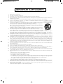
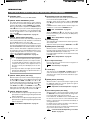
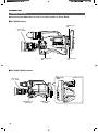
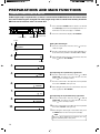
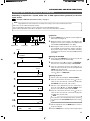
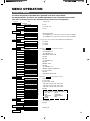
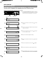
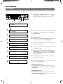
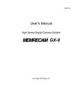
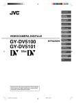
R
RM-P210 REMOTE CONTROL UNIT
INTRODUCTION
CONNECTION
PREPARATIONS AND
MAIN FUNCTIONS
CAMERA
ADJUSTMENTS
REMOTE CONTROL UNIT
RM-P210
INSTRUCTIONS
MENU OPERATION
GENERAL
REMOTE CONTROL UNIT RM-P210
TALLY
CALL
FULL AUTO
F1
F3
MENU/SHUTTER
GAIN
SHUTTER
BARS
F2
F4
MENU
SHUTTER
VARIABLE
PUSH-ON
PUSH-ON
PAINT
WHITE
W.BAL
HIGH
B
MID
LOW
I
A
R
B
POWER
IRIS
MASTER BLACK
AUTO
STEP
PRESET
AUTO
MANU
GAIN
INTERCOM
LEVEL
O
DOWN
UP
DOWN
UP
CLOSE
OPEN
For Customer Use:
Enter below the Model No. and Serial
No. which are located on the bodie.
Retain this information for future reference.
Model No.
RM-P210
Serial No.
d
SC961002-003-H
IMPORTANT SAFEGUARDS
1.
2.
3.
4.
5.
6.
7.
8.
9.
10.
11.
12.
13.
14.
15.
16.
17.
18.
19.
2
Read all of these instructions.
Save these instructions for later use.
All warnings on the product and in the operating instructions should be adhered to.
Unplug this appliance system from the wall outlet before cleaning. Do not use liquid cleaners or aerosol cleaners. Use
a damp cloth for cleaning.
Do not use attachments not recommended by the appliance manufacturer as they may cause hazards.
Do not use this appliance near water – for example, near a bathtub, washbowl, kitchen sink, or laundry tub, in a wet
basement, or near a swimming pool, etc.
PORTABLE CART WARNING
Do not place this appliance on an unstable cart, stand, or table. The appliance may fall, caus- (symbol provided by RETAC)
ing serious injury to a child or adult, and serious damage to the appliance.
Use only with a cart or stand recommended by the manufacturer, or sold with the appliance.
Wall or shelf mounting should follow the manufacturer’s instructions, and should use a
mounting kit approved by the manufacturer.
An appliance and cart combination should be moved with care. Quick stops, excessive force,
and uneven surfaces may cause the appliance and cart combination to overturn.
Slots and openings in the cabinet and the back or bottom are provided for ventilation, and to
S3126A
insure reliable operation of the appliance and to protect it from overheating, these openings
must not be blocked or covered. The openings should never be blocked by placing the appliance on a bed, sofa, rug, or
other similar surface. This appliance should never be placed near or over a radiator or heat register. This appliance
should not be placed in a built-in installation such as a bookcase unless proper ventilation is provided.
This appliance should be operated only from the type of power source indicated on the marking label. If you are not
sure of the type of power supplied to your home, consult your dealer or local power company. For appliance designed
to operate from battery power, refer to the operating instructions.
This appliance system is equipped with a 3-wire grounding type plug (a plug having a third (grounding) pin). This plug
will only fit into a grounding-type power outlet. This is a safety feature. If you are unable to insert the plug into the
outlet, contact your electrician to replace your obsolete outlet. Do not defeat the safety purpose of the grounding plug.
For added protection for this product during a lightning storm, or when it is left unattended and unused for long periods
of time, unplug it form the wall outlet and disconnect the antenna or cable system. This will prevent damage to the
product due to lightning and power-line surges.
Do not allow anything to rest on the power cord. Do not locate this appliance where the cord will be abused by
persons walking on it.
Follow all warnings and instructions marked on the appliance.
Do not overload wall outlets and extension cords as this can result in fire or electric shock.
Never push objects of any kind into this appliance through cabinet slots as they may touch dangerous voltage points or
short out parts that could result in a fire or electric shock. Never spill liquid of any kind on the appliance.
Do not attempt to service this appliance yourself as opening or removing covers may expose you to dangerous voltage
or other hazards. Refer all servicing to qualified service personnel.
Unplug this appliance from the wall outlet and refer servicing to qualified service personnel under the following conditions:
a. When the power cord or plug is damaged or frayed.
b. If liquid has been spilled into the appliance.
c. If the appliance has been exposed to rain or water.
d. If the appliance does not operate normally by following the operating instructions. Adjust only those controls that
are covered by the operating instructions as improper adjustment of other controls may result in damage and will
often require extensive work by a qualified technician to restore the appliance to normal operation.
e. If the appliance has been dropped or the cabinet has been damaged.
f. When the appliance exhibits a distinct change in performance – this indicates a need for service.
When replacement parts are required, be sure the service technician has used replacement parts specified by the
manufacturer that have the same characteristics as the original part. Unauthorized substitutions may result in fire,
electric shock, or other hazards.
Upon completion of any service or repairs to this appliance, ask the service technician to perform routine safety checks
to determine that the appliance is in safe operating condition.
SAFETY PRECAUTIONS
CAUTION
RISK OF ELECTRIC SHOCK
DO NOT OPEN
CAUTION :
TO REDUCE THE RISK OF ELECTRIC SHOCK,
DO NOT REMOVE COVER (OR BACK).
NO USER SERVICEABLE PARTS INSIDE.
REFER SERVICING TO QUALIFIED SERVICE PERSONNEL.
The lightning flash with arrowhead symbol,
within an equilateral triangle is intended to alert
the user to the presence of uninsulated “dangerous voltage” within the product's enclosure
that may be of sufficient magnitude to constitute a risk of electric shock to persons.
The exclamation point within an equilateral triangle is intended to alert the user to the presence of important operating and maintenance
(servicing) instructions in the literature accompanying the appliance.
WARNING: TO REDUCE THE RISK OF FIRE
OR ELECTRIC SHOCK, DO NOT EXPOSE
THIS APPLIANCE TO RAIN OR MOISTURE.
AVERTISSEMENT :
POUR EVITER LES RISQUES D’INCENDIE
OU D’ELECTROCUTION, NE PAS EXPOSER
L’APPAREIL A L’HUMIDITE OU A LA PLUIE.
Information for USA
This device complies with Part 15 of the FCC Rules.
Changes or modifications not approved by JVC could void
the user's authority to operate the equipment.
INFORMATION (FOR CANADA)
RENSEIGNEMENT (POUR CANADA)
This Class B digital apparatus complies with Canadian ICES003.
INTRODUCTION
Thank you for purchasing this JVC product.
Before operating this unit, please read the instructions carefully to ensure the best possible performance.
These instructions are for RM-P210U.
Contents
INTRODUCTION
Features ...........................................................................
Provided Accessories and Documents ............................
Precautions for Proper Use .............................................
Controls, Connectors and Indicators ...............................
Front panel ...................................................................
Rear panel ....................................................................
4
4
4
5
5
7
CONNECTION
Example of Basic Connection .......................................... 8
Example of RM-P210 (Connection of 2 units) ................. 9
Camera Setup ................................................................ 10
Turning the Power ON .................................................... 11
PREPARATIONS AND MAIN FUNCTIONS
Camera Cable Length Setup .........................................
Adjustments for Genlock Operation ...............................
Intercom .........................................................................
Camera Operator Call ....................................................
Tally Input .......................................................................
Function Keys ................................................................
12
13
14
14
14
15
CAMERA ADJUSTMENTS
Shutter Speed Adjustment .............................................
Gain Adjustment ............................................................
Iris Adjustment ...............................................................
White Balance Adjustment .............................................
16
16
17
18
MENU OPERATION
Flow of Menus ...............................................................
Menu Setup Method ......................................................
GENLOCK Menu ...........................................................
CABLE Menu .................................................................
FILE Menu .....................................................................
PROCESS Menu ...........................................................
OPERATION Menu ........................................................
LCD MODE Menu ..........................................................
SYSTEM RESET Menu .................................................
19
20
21
21
22
23
25
26
27
GENERAL
Warning Messages ........................................................
Error Messages .............................................................
Functions Available Depending on Camera Models ......
Troubleshooting .............................................................
Specifications .................................................................
28
28
29
30
31
Cet appareil numérique de la class B est conforme á la norme
NMB-003 du Canada.
Changes or modifications not approved by JVC could void the
user's authority to operate the equipment.
This unit is designed for professional use only.
Due to design modifications, data given in this instruction book
are subject to possible change without prior notice.
3
INTRODUCTION
FEATURES
Cable extension up to 100 meters
The cable between the camera and the RM-P210 Remote
Control Unit can be extended up to 100 meters using the
optional VC-P110 series camera cables. Even when the
cable is extended, the power to the camera is supplied from
the RM-P210 so there is no need to provide a separate
power supply for the camera.
Genlock Function Built In
Genlocking is possible using a composite video (VBS) or a
black burst (BB) signal. The SC and H phases can be adjusted from the front panel.
Camera control using serial communication
The camera control signals are sent by the serial data transmission method.
The camera and the RM-P210 are connected by two data
lines so that the CPUs incorporated in the camera and the
RM-P210 are in intercommunication, thus facilitating accurate camera control operations.
Multiple output circuits
In addition to two composite video output circuits (VBS),
the R/G/B component signals, Y/R-Y/B-Y component signals or separate Y/C signals (for S-VHS VCR) can be selected according to the purpose or application.
PROVIDED ACCESSORIES AND DOCUMENTS
R
CAMERA CONTROL UNIT
RM-P210
Power cord
INSTRUCTIONS
Instructions
PRECAUTIONS FOR PROPER USE
Do not supply power to the RTS terminals at the rear. These
terminals are not designed to accept a power supply.
To prolong the service life of the RM-P210, do not use it or
store it in the following places.
A place subject to extremely high or low temperatures.
A place subject to excessive vibration.
A place subject to excessive dust.
A place subject to high humidity.
A place near to a strong source of noise.
Do not apply strong vibrations or impact to the RM-P210
during installation or transportation.
If the supply voltage is too high or low, the service life of the
RM-P210 may be reduced or it may not be able to provide
an optimum performance.
Do not connect or disconnect the camera cable connector
while the RM-P210 is ON.
After turning the RM-210 OFF, wait at least 10 seconds
before turning it ON again.
Noise may interfere with the video when the RM-210 is installed near a source of strong magnetism, such as a radio
or TV transmitting antenna, power transformer or motor.
While the values set by using the menus are retained in the
memory even after the unit is turned off, those set using the
front panel switches and controls are retained for about 10
days only and then the factory-set defaults are reset.
As the LCD contrast is reduced at low temperatures, it should
be re-adjusted before use in such conditions.
REF. : Item “6A: CONTRAST” on page 26.
When a transceiver or cellular phone is used near to a RM210 or to a camera connected to it, noise may interfere with
the video. However, this is not a malfunction.
4
When an intercom is used, radio interference may occasionally affect any system that is connected to the RM-P210.
In such a case the INTERCOM G (GND) terminal provided
to the RM-P210 should be grounded.
In a multiple camera setup, if the adjustments made to the
different cameras deviate significantly, the cameras may not
be able to function satisfactorily. Be sure to adjust the cameras accordingly before using them with the RM-P210.
Use camera cables with standard lengths, as specified.
Otherwise, the camera cable compensation may not be able
to work efficiently.
The RM-P210 can be connected with the following cameras:
● GY-DV550
● KY-D29
● KY-D29W
● KY-27C
● KY-19
For the viewfinder to be used with each camera model, see
page 8. The controllable functions vary depending on the
camera model.
REF. : "Functions Available Depending on Camera
Models" on page 29.
When connecting the RM-P210 to the camera, do not connect a local remote controller to the camera.
If the RM-P210 is rack-mounted, be sure to insert ventilated panels above and below it in order to improve ventilation. Do not stack two RM-P210 units or place any object
on top of a RM-P210 unit.
To save power consumption, turn the RM-P210 OFF when
it is not in use.
INTRODUCTION
CONTROLS, CONNECTORS AND INDICATORS
Front panel
1 2 34
56 7
8 9 0
!
REMOTE CONTROL UNIT RM-P210
TALLY
CALL
FULL AUTO
F1
F3
MENU/SHUTTER
GAIN
SHUTTER
BARS
F2
F4
MENU
SHUTTER
VARIABLE
PUSH-ON
PUSH-ON
PAINT
WHITE
W.BAL
HIGH
B
MID
LOW
I
A
R
B
POWER
IRIS
MASTER BLACK
AUTO
STEP
PRESET
AUTO
MANU
GAIN
O
INTERCOM
LEVEL
¤⁄
DOWN
)
(
1 Intercom jack
Connect the intercom headset to this jack.
REF. : “Intercom” on page 14.
2 [INTERCOM LEVEL] control
Use this knob to adjust the intercom earphone volume.
3 [TALLY] lamp
This lamp lights when a signal is input to the TALLY terminals 2 on the rear panel.
It lights in red when a tally signal is input to the TALLY
PGM terminal on the rear panel or in green when a tally
signal is input to the TALLY PVW terminal. It blinks in red
when there is a CALL signal from the camera.
NOTE
The order of priority among the above signals are; CALL
(red blinking), TALLY PGM (red lighting) then TALLY PVW
(green lighting).
4 [CALL] button (with lamp)
The camera operator can also be called without using the
intercom. When this button is pressed once, the button lamp
lights up and the tally lamp on the camera blinks to inform
the camera operator of a call. Pressing this button again
turns off both the button lamp and tally lamp on the camera.
NOTE
When the CALL button is pressed during VF-P400 operation, the picture on the viewfinder screen may vibrate. However, this is not a malfunction.
5 [GAIN - VARIABLE] control with ON/OFF button
When the button is pressed, the VARIABLE GAIN mode is
switched ON and OFF alternately.
The GAIN lamp 6 lights when the VARIABLE GAIN mode
is ON.
When the GAIN mode is set to VARIABLE, the GAIN value
can be varied from 0.1 dB (or 1.0 dB) to 18 dB in 0.1 dB (or
1.0 dB) steps. The variation per step and the maximum
gain value can be changed under the following items.
REF. : Items “5B: V. GAIN STEP” and “5C: V. GAIN
MAX” on page 25.
UP
DOWN
*& ^
UP
CLOSE
OPEN
%$#@
6 [GAIN] lamp
This lamp lights when the gain control is in the VARIABLE
GAIN mode.
7 [GAIN - STEP LOW/MID/HIGH] switch
The gain value can be selected according to the position
of this switch.
HIGH : REF. Gain value set by item “5F: GAIN HIGH” on page 25.
MID : REF. Gain value set by item “5E: GAIN MID” on page 25.
LOW : REF. Gain value set by item “5D: GAIN LOW” on page 25.
The selected gain value is shown in the LCD display
every time that the position of this switch is changed.
)
8 [MASTER BLACK] control
Use this knob to adjust the pedestal level, which is the
black reference (master black) value.
9 [IRIS - AUTO/MANU] button (with lamp)
When this button is pressed so that the lamp in it lights the
lens iris is set to the manual iris control mode. The lens iris
level may be adjusted in this mode by using the IRIS control 0.
When this button is pressed so that the lamp in it turns off,
the lens iris is set to the auto iris control mode.The auto
iris level can be fine adjusted with the IRIS control 0.
0 [IRIS - CLOSE-OPEN] control
When the manual iris control mode is set (which is indicated by the lighting of the lamp in the AUTO/MANU button 9), use this knob to adjust the iris aperture between
CLOSE and OPEN.
When the iris mode is AUTO (when the lamp in the button is
not lit up), the auto iris level can be fine adjusted with this
knob.
REF. “Iris Adjustment” on page 17.
5
INTRODUCTION
CONTROLS, CONNECTORS AND INDICATORS (CONTINUED)
! [POWER] switch
Press this switch to turn the power ON and OFF.
@ [WHITE - W.BAL B/A/PRESET] switch
This switch switches the white balance control setting between the value stored in Memory B (AUTO 2), that stored
in Memory A (AUTO 1) and the PRESET value (3200K).
When the white-balance adjustment is PRESET and the
PAINT $ button is pressed so that the lamp in it lights up,
the white-balance adjustment is set to the Manual mode,
in which the white-balance can be adjusted with the R/B
gain controls %.
REF. : “White Balance Adjustment” on page 18.
# [WHITE - AUTO] button (with lamp)
Press this button to start an auto white-balance adjustment
of the camera (within a second). This button is activated only
when the W.BAL switch is set to “A” or “B”.
When the camera in use has the AUTO SETUP function,
pressing and holding this button for more than a second initiates the AUTO SETUP mode and then starts the auto blackbalance and auto white-balance adjustment operations. If
the camera does not have an AUTO SETUP function, pressing and holding this button for more than a second starts
only the auto white-balance adjustment operation.
REF. : “White Balance Adjustment” on page 18.
NOTE
● When the camera performs the auto white operation
or other AUTO SET operations, the lamp in this button normally lights up and turns off when the camera
completes the operation. If the adjustment has not
been done correctly, the LCD display shows an error
message.
● The lamp in this button also lights up when the FAW
(Full-time Auto White-balance) adjustment function of
the camera is functioning.
$ [WHITE - PAINT] button (with lamp)
When this button is pressed so that the lamp in it lights up,
the R and B gain values can be adjusted using the R and
B controls %. If the W.BAL switch @ is set to “A” or “B”,
the white paint adjustment (fine adjustment of the R and B
gain) can be performed using the R and B controls %.
If the W.BAL switch @ is set to PRESET, the lamp in this
button lights up and the R and B controls can vary the R
and B gain values by a larger amount than usual % .
% [WHITE - R/B] gain controls
R : Use this knob to fine-adjust the R gain during the white
paint operation or adjust the R gain during manual white
balance adjustment.
B : Use this knob to fine-adjust the B gain during the white
paint operation or adjust the B gain during manual white
balance adjustment.
REF. : “White Balance Adjustment” on page 18.
6
^ [SHUTTER] control with ON/OFF button
When this knob is pressed, the shutter speed variation function is turned alternately ON and OFF.
When the shutter speed variation is ON, the SHUTTER
lamp & lights and turning the knob will vary the shutter
speed.
In STEP mode the shutter speed is varied in stages, fine
adjustments can be made in VARIABLE mode.
REF. : Item “5A: SHUTTER” on page 25.
When the MENU lamp * is lit, turn the knob to switch
between menu items, press the knob (to the ON position)
to select an item.
REF. : “Menu Setup Method” on page 20.
& [SHUTTER] lamp
This lamp lights up to indicate that the shutter speed variation facility is ON.
Adjust the shutter speed using the SHUTTER control ^.
* [MENU] button (with lamp)
When this button is held depressed for about 1 second,
the button lamp is lit and the menu becomes variable. (The
SHUTTER and GAIN lamps should be off.)
Pressing this button terminates a menu and turns the lamp
in the button off.
REF. : “Menu Setup Method” on page 20.
( [F1 to F4] function keys
Each of these keys can turn the function assigned to it
alternately ON and OFF.
REF. : “Function Keys” on page 15.
) LCD display
This panel shows the SHUTTER and GAIN settings as
well as the functions assigned to the function buttons.
This panel is also used to show menus and various operation messages.
⁄ [BARS] button (with lamp)
When this button is pressed, the lamp in it lights up and
the RM-P210 outputs the color bar signal. This signal is
used during genlock operation.
REF. : “Adjustments for Genlock Operation” on page 13.
¤ [FULL AUTO] button (with lamp)
When this button is pressed, the lamp in it lights up and
the RM-P210 enters the FAS (Full-Auto Shooting) mode.
Pressing the button again turns the lamp off.
In the FAS mode, the BARS mode is switched OFF, and
the auto level control, auto iris control and full-auto white
balance control functions are performed automatically in
an integrated manner.
For details, please read the description of the FAS function in the manual of the camera in use.
The functions that can be controlled are variable depending on which camera model is connected.
REF. : “Function Available Depending on Camera
Models” on page 29.
INTRODUCTION
CONTROLS, CONNECTORS AND INDICATORS (CONTINUED)
Rear panel
TALLY
PGM
PVW
INTERCOM
C
H
C
AUX VIDEO INPUT
GENLOCK INPUT
VIDEO OUTPUT
R/R-Y
G
G/Y
COMPOSITE VIDEO
RTS
1
2
3
Y/C OUT
B/B-Y
CAMERA CABLE
4
1 [AC ` IN] connector
Connect this socket to a commercial power supply outlet
using the power cord provided.
2 [TALLY] terminals
These terminals input the tally signals.
● When the contact between the PGM (Program) and C
(Common) terminals is closed, the TALLY lamp 3 on
the front panel lights in RED.
● When the contact between the PVW (Preview) and C
(Common) terminals is closed, the TALLY lamp 3 on
the front panel lights in GREEN.
REF. : “Tally Input” on page 14.
3 [INTERCOM] terminals
5
6
7
8
9
7 [COMPOSITE VIDEO] signal output connectors
These terminals output two lines of VBS (composite video)
signals.
8 Y/C OUT connector (4-pin)
This connector outputs the separate Y/C video signals.
NOTE
This connector outputs Y/C signals only when Y/C is
selected as the output from the R/R-Y, G/Y and B/B-Y
connectors 6.
9 [CAMERA CABLE] connector (26-pin)
Connect this socket to a camera using the optionally available camera cables.
These terminals input and output the intercom signals.
In a system composed of multiple cameras and remote
control units, the intercom function provides intercommunication between operators.
REF. : “Intercom” on page 14.
4 [AUX VIDEO INPUT] connectors
These connectors are used to input the return video signal, which returns the SEG (Special Effects Generator) or
switcher output signal to the camera viewfinder.
The two terminals are loop-through connected inside to
enable a bridge connection.
They are terminated automatically when they are not
bridge-connected.
5 [GENLOCK INPUT] connectors
These connectors are used to input the VBS/BB signal for
use in genlocking.
They are terminated automatically when they are not
bridge-connected.
6 [R/R-Y, G/Y, B/B-Y] component video signal
output connectors
The settings of the output signals from these connectors
can be switched between RGB, R-Y/Y/B-Y and Y/C using
the SIG SELECT switch on the camera adapter or by using the menu setup of the camera.
When Y/C is selected, the Y signal is output from the G
connector and the C signal is output from the R connector.
Camera Cables (Optional)
The VC-P110 series camera cables that can be used to connect a camera to the RM-P210 are available in four lengths as
listed below.
VC-P110 : 5 meters
VC-P112 : 20 meters
VC-P113 : 50 meters
VC-P114 : 100 meters
A menu setup is required according to the cables in use.
REF. : “Setup of Camera Cable Length” on page 12.
NOTE
● If it is required to extent the cable, use the KA-280
extension connector.
● The total cable length should not exceed 100 meters.
7
CONNECTION
EXAMPLE OF BASIC CONNECTION
Standard connection of the RM-P210 (Connection of a single unit)
Intercom headset
KA-310
OPERATE/WARNING
LIGHT
RESET
FILTER
ALARM
1 3200k
2 5600k+1/8ND
3 5600k+1/64ND
SHUTTER STATUS
RM
VTR
COUNTER
CTL
TC
UB
CH-1
LEVEL
BLACK
CH-2
CH-1
Camera cable
VC-P110
CH-2
AUTO
MANUAL
FRONT
REAR
AUDIO SELECT
AUDIO INPUT
OFF
CALL
LOLUX
STRETCH
NORMAL
COMPRESS
BACK L
NORMAL
SPOT L
LEVEL
ON
CH-1 AUDIO CH-2
FULL AUTO
INCOM
MIC
CARBON
DYNAMIC
INCOM
MIC
MONITOR
MENU
AUTO IRIS
MODE
ON
OFF
MONITOR
SELECT
CH-1
MIX
CH-2
RM
OFF
DC IN
/BATT.
POWER
VTR
GAIN
NG
OUTPUT WHT.BAL
OPERATE
ON
OFF
GY-DV550
Intercom headset
KA-310
RM-P210
TALLY
PGM
PVW
INTERCOM
C
H
C
AUX VIDEO INPUT
GENLOCK INPUT
VIDEO OUTPUT
R/R-Y
G
G/Y
Y/C OUT
B/B-Y
COMPOSITE VIDEO
RTS
CAMERA CABLE
VBS
To power supply
YC
Monitor
VCR
● Connection of Cameras and Viewfinders ( : Usable, : Not usable, — : Not connectable)
Viewfinder
VF-P115B
VF-P115
VF-P550B VF-P550W
VF-P400
VF-P116W
VF-P116
Camera
GY-DV550
KY-D29
KY-D29W
KY-27C
KY-19
● When the RM-P210 is connected to a camera, a local remote controller cannot be connected to the camera.
8
CONNECTION
EXAMPLE OF RM-P210 (CONNECTION OF 2 UNITS)
Standard connection of RM-P210 (Connection of 2 units)
Intercom headset
KA-310
OPERATE/WARNING
LIGHT
RESET
FILTER
ALARM
1 3200k
2 5600k+1/8ND
3 5600k+1/64ND
SHUTTER STATUS
RM
VTR
COUNTER
CTL
TC
UB
CH-1
CH-2
CH-1
FRONT
REAR
AUDIO INPUT
OFF
CALL
LOLUX
STRETCH
NORMAL
COMPRESS
BACK L
NORMAL
SPOT L
Camera cable
VC-P110
CH-2
AUTO
MANUAL
AUDIO SELECT
LEVEL
BLACK
LEVEL
ON
CH-1 AUDIO CH-2
FULL AUTO
INCOM
MIC
CARBON
DYNAMIC
INCOM
MIC
MONITOR
MENU
AUTO IRIS
MODE
ON
OFF
MONITOR
SELECT
CH-1
MIX
CH-2
RM
OFF
DC IN
/BATT.
POWER
VTR
GAIN
NG
OUTPUT WHT.BAL
OPERATE
ON
OFF
Monitor
GY-DV550
Intercom headset
KA-310
RM-P210
TALLY
PGM
PVW
INTERCOM
C
H
C
AUX VIDEO INPUT
GENLOCK INPUT
VIDEO OUTPUT
R/R-Y
G
G/Y
Y/C OUT
B/B-Y
COMPOSITE VIDEO
RTS
CAMERA CABLE
YC
To power supply
BB OUT
Return
video
RTS unit
Tally
Intercom
YC
Special effects
generator, etc.
RM-P210
TALLY
PGM
PVW
INTERCOM
C
H
C
AUX VIDEO INPUT
GENLOCK INPUT
VIDEO OUTPUT
R/R-Y
G
G/Y
Y/C OUT
B/B-Y
COMPOSITE VIDEO
RTS
CAMERA CABLE
To power supply
Intercom headset
KA-320
Monitor
Camera cable
VC-P110
● If more than three RM-P210 units are connected, the intercom volume level will be reduced.
9
CONNECTION
CAMERA SETUP
Before turning the RM-P210 on, be sure to set up the camera as shown below.
GY-DV550 camera
MODE switch
RM
IRIS switch
“A” or “AUTO”
OPERATE/WARNING
LIGHT
RESET
FILTER
ALARM
1 3200k
2 5600k+1/8ND
3 5600k+1/64ND
SHUTTER STATUS
MODE
ON
OFF
RM
VTR
MONITOR
SELECT
COUNTER
CH-1
MIX
CH-2
CTL
TC
UB
INCOM
MIC
CARBON
DYNAMIC
INCOM
MIC
MONITOR
MENU
CH-2
CH-1
CH-2
AUTO
MANUAL
FRONT
REAR
AUDIO SELECT
AUDIO INPUT
OFF
CH-1 AUDIO CH-2
CALL
LEVEL
AUTO IRIS
FULL AUTO
BLACK
LOLUX
STRETCH
NORMAL
COMPRESS
BACK L
NORMAL
SPOT L
LEVEL
ON
CH-1
RM
OFF
DC IN
/BATT.
POWER
VTR
GAIN
NG
BAL
OUTPUT WHT.
OPERATE
ON
OFF
POWER switch
RM
OPERATE switch
ON
KY-D29/KY-D29W camera
Right side
panel
IRIS switch
“A” or “AUTO”
VTR/RM switch
RM
AUDIO
LEVEL
–20dB
MIC
EAR PHONE
CAM
Mg
SELECT
SIG
COMP
BETA
RGB
VTR
MIX
INCOM LEVEL
AD
MODE
VTR
Y/C
–60dB
RM
VTR/RM
INTERCOM
MIC INPUT
Y/C OUTPUT
12V DC}INPUT
OPERATE switch
ON/ST-BY
10
POWER switch
VTR/RM
CONNECTION
TURNING THE POWER ON
REMOTE CONTROL UNIT RM-P210
PAINT
WHITE
MASTER BLACK
AUTO
1.
Connect the camera to the RM-P210 using a proper connection method.
2.
Set the camera switches as shown on the previous page.
3.
Press the POWER switch of the RM-P210 to ON.
POWER
IRIS
W.BAL
P
B
MID
I
A
R
B
PRESET
AUTO
MANU
O
CLOSE
OPEN
POWER switch
NOTE
● When an item is controllable from both the RM-210 and the camera, the control from the camera is defeated. Note that the
items that are controllable from the RM-210 are variable depending on the camera models.
● When connecting the RM-P210 to the camera, do not connect a local remote controller to the camera.
11
PREPARATIONS AND MAIN FUNCTIONS
CAMERA CABLE LENGTH SETUP
Cable length setup is required when a camera is connected to the RM-P210 for the first time or when
the camera cable length is changed. The cable length setup value is stored in the memory inside the
RM-P210 and is held even after it is turned OFF.
FULL AUTO
F1
F3
MENU/SHUTTER
GAIN
SHUTTER
P
1.
Press and hold the MENU button for about 1 second until
the LCD display shows the menu display. Turn the control knob to move the cursor ( ) to "2: CABLE".
2.
Press the control knob to display “2A: LENGTH”.
STEP
HIGH
2. CABLE
BARS
F2
F4
MENU
SHUTTER
VARIABLE
PUSH-ON
PUSH-ON
MID
LOW
R
GAIN
M
DOWN
UP
DOWN
UP
Control knob
LCD display
MENU button
Cursor
1.
Setting the cable length
1: GENLOCK
2: CABLE
Cursor
2.
2A: LENGTH
5M
3.
Press the control knob to move the cursor ( ) to the currently set length.
4.
Turn the control knob to select the cable length that is to
be used in meters (variable to 5M, 20M, 50M or 100M).
5.
After setting the value, press the control knob to move the
cursor ( ) back to “2A: LENGTH”.
Setting
3.
2A: LENGTH
5M
4.
Fine adjusting the Y (luminance) signal level
2A: LENGTH
100M
6.
Turn the control knob to move the cursor ( ) to “2B: Y
CABLE EQ”, then press the control knob to move the
cursor ( ) to the currently set value.
7.
Turn the control knob to fine adjust the Y level (variable
from -128 to NORMAL and up to 127).
8.
After setting the value, press the control knob to move the
cursor ( ) back to “2A: LENGTH”.
2B: Y CABLE EQ
NORMAL
7.
6.
2B: Y CABLE EQ
127
Fine adjusting the C (Chrominance) signal level
9.
9.
2C: C CABLE EQ
NORMAL
10.
Turn the control knob to move the cursor ( ) to “2C: C
CABLE EQ”, then press the control knob to move the
cursor ( ) to the currently set value.
10. Turn the control knob to fine adjust the C level (variable
2C: C CABLE EQ
1
from -128 to NORMAL and up to 127).
11. After setting the cable length, Y level and C level, press
the MENU button to return to the previous display.
NOTE
When the above adjustment is performed, the color
phase (subcarrier phase = SC) varies.
12
PREPARATIONS AND MAIN FUNCTIONS
ADJUSTMENTS FOR GENLOCK OPERATION
Genlocking is required for a system, which uses an SEG (special effects generator) as the main
signal source.
REF. : “Example of RM-P210 (Connection 2 units) ” on page 9.
NOTE
● The following adjustments can be made more accurately when using a vectorscope and waveform monitor.
● Be sure to use an underscanned video monitor.
● It is not permitted to genlock the system components using a VCR playback signal.
● Before phase adjustment, wait a little for the phases of the connected components to stabilize.
Preparation
FULL AUTO
F1
F3
MENU/SHUTTER
GAIN
SHUTTER
P
STEP
HIGH
BARS
F2
F4
MENU
SHUTTER
VARIABLE
PUSH-ON
PUSH-ON
1.
Press the BARS button to output the color bar signal. The
button lamp should light up.
2.
Output the built-in color bar signal of the SEG from the
program connector on the front panel of the SEG. (Refer
to the INSTRUCTIONS MANUAL of the SEG.)
3.
Observing the monitor screen at the same time, adjust
the H PHASE (horizontal phase) and SC (subcarrier
phase) while using the switch on the SEG to alternately
change between color bars of the internal RM-P210 that
of the SEG.
MID
LOW
R
GAIN
M
DOWN
UP
DOWN
UP
Control knob
BARS button
LCD display
MENU button
Cursor
4.
1: GENLOCK
2: CABLE
Adjusting the H PHASE
Item
5.
Setting
1A: H PHASE
128
4.
Press and hold the MENU button for about 3 seconds until
the LCD display shows the menu display.
5.
Ensure that the cursor ( ) is located on “1: GENLOCK”,
then press the control knob to display “1A: H PHASE”.
6.
Press the control knob to move the cursor ( ) to the currently set value, then turn the control knob to adjust the H
PHASE value (from 0 to 255).
After the adjustment, press the control knob to move the
cursor ( ) back to “1: GENLOCK”.
Cursor
6.
1A: H PHASE
255
7.
Adjusting SC phase
7.
8.
1B: SC COARSE
0°
8.
9.
1B: SC COARSE
90°
Turn the control knob to display “1B: SC COARSE”.
Press the control knob to move the cursor ( ) to the currently set value, then turn the control knob to adjust the
SC COARSE value (to 0°, 90°, 180° or 270°).
After the coarse adjustment, press the control knob to
move the cursor ( ) back to “1B: SC COARSE”, then
press the control knob to display “1C: SC FINE”.
10. Press the control knob to move the cursor (
9.
1C: SC FINE
128
10.
1C: SC FINE
255
) to the currently set value, then turn the control knob to adjust the
SC FINE value (from 0 to 255).
NOTE
If the SC phase cannot be adjusted properly, restart the
procedure from the SC COARSE adjustment in step 7
again.
11. After the adjustment, press the MENU button to return to
11.
STR
OFF
ALC
CMP
0dB
LUX
the previous display.
12. Press the BARS button to stop the color bar signal output.
13
PREPARATIONS AND MAIN FUNCTIONS
INTERCOM
Intercommunications between operators are necessary in a system composed of multiple cameras
and remote control units.
Rear panel
TALLY
PGM
PVW
INTERCOM
C
H
C
AUX VIDEO INPUT
G
G
RTS
Front panel
INTERCOM LEVEL control
TALLY
CALL
FULL AUTO
F1
SHUTTER
2. CABLE
BARS
F2
GAIN
INTERCOM
LEVEL
The intercom employs the RTS system.
If it is required to change this to a 2-wire system, consult your
nearest JVC-authorized service agent. (The modification will
then be carried out with charge.)
An intercom jack is provided on the front panel of the RM-P210.
The volume level of the headset’s earphone can be adjusted
using the INTERCOM LEVEL control.
NOTE
● Examples of suitable headsets
JVC KA-310 (Microphone 50 W/DC, earphone 150 W/1kHz)
Headsets from other manufacturers with:
Microphone output impedance: 50 W to 100 W
Earphone input impedance: 50 W to 300 W
● The RM-P210 has been set at the factory to be compatible with a dynamic type headset. If it is required to use a
carbon type headset, the setting of the internal circuitry
should be changed; consult your nearest JVC-authorized
service agent. (The modifications and adjustments will
be carried out with charge.)
Intercom jack
CAMERA OPERATOR CALL
This function makes it possible to call the camera operator without using the intercom. The camera
operator is informed of the call by the blinking of the tally lamp on the camera.
TALLY
CALL
FULL AUTO
When the CALL button is pressed, the button lamp is lit and
the tally lamp on the camera blinks. Pressing the button again
turns off both the button lamp and the blinking of the camera’s
tally lamp.
F1
SHUTTER
2. CABLE
BARS
F2
GAIN
INTERCOM
LEVEL
NOTE
The tally lamp on the camera does not blink or light when
either the camera or the RM-P210 are switched off.
When the CALL button of the camera is pressed, the TALLY
lamp of RM-P210 blinks in red.
CALL button
TALLY INPUT
The TALLY lamp on the front panel lights when signals are applied to the TALLY input terminals on
the rear panel.
TALLY
PGM
PVW
INTERCOM
C
H
C
AUX VIDEO INPUT
G
RTS
C (Common) terminal
PVW (Preview) terminal
PGM (Program) terminal
14
G
● The TALLY lamp lights in red when contact is made between the PGM (Program) and C (Common) terminals.
● The TALLY lamp lights in green when contact is made between the PVW (Preview) and C (Common) terminals.
NOTE
The RM-P210 has been set at the factory in the “make contact mode”. If it is required to set it to the “voltage supplied
mode”, the setting of the internal circuitry should be
changed; consult your nearest JVC-authorized service
agent. (The modification will then be carried out with charge.)
PREPARATIONS AND MAIN FUNCTIONS
FUNCTION KEYS
Up to four of the functions listed at the bottom of this page can be assigned to function keys F1 to
F4 so that each function can be switched on or off by pressing the corresponding key.
(For the assignment of functions: REF. Items 5H to 5K, “FUNC1” to “FUNC4” in the OPERATION MENU description on
page 25.)
In the example shown on the left, the functions are assigned
as shown in the following table.
<Example of factory setting>
F1
F3
Key Display
FULL AUTO
F1
F3
MENU/S
SHUTTER
STR
CMP
BARS
OFF
0dB
ALC
LUX
F2
F4
MENU
GAIN
M
DO
F2
LCD display
F4
1.
Function
F1
STR
BLACK STRETCH
F2
CMP
BLACK COMPRESS
F3
ALC
ALC + EEI
F4
LUX
LOLUX
In the figure on the left, the lamps in all the function keys are
off, this indicates that all these functions are off.
With certain cameras, “---” may be displayed when none of
the above functions are available.
Switching an assigned function on/off
FULL AUTO
F1
F3
MENU/S
SHUTTER
1.
BLACK STRETCH
ON
BARS
F4
F2
MENU
When the F1 key is pressed, the BLACK STRETCH function assigned to the F1 key is switched from OFF to ON
and the lamp in the key lights up.
GAIN
M
NOTE
● The on/off condition of each function key can be set
independently.
DO
2.
FULL AUTO
2.
F1
F3
MENU/S
SHUTTER
BLACK STRETCH
When the F1 key is pressed again, the BLACK STRETCH
function is switched from ON to OFF and the lamp in the
key turns off.
OFF
BARS
F2
F4
MENU
GAIN
M
DO
Checking the assigned functions
Press the MENU button to display the functions assigned to
the function keys for about 3 seconds, in up to 7 characters
per function as shown in the figure on the left.
FULL AUTO
F1
F3
MENU/S
NOTE
When BLACK STRETCH and BLACK COMPRESS are
assigned to two of the F1 to F4 keys, it is not permitted
to switch the two functions ON simultaneously. It is not
permitted to switch both ALC+EEI and LOLUX ON.
SHUTTER
BLK STR
BLK CMP
BARS
ALC+EEI
LOLUX
F2
F4
MENU
GAIN
M
DO
MENU button
Function Name
NONE
BLACK STRETCH
BLACK COMPRESS
ALC + EEI
LOLUX
FAW
AUTO KNEE
SKIN DETAIL
COLOR MATRIX
DETAIL
DNR
Display (3-Character)
STR
CMP
ALC
LUX
FAW
KNE
SKN
MAT
DTL
DNR
Display (7-Character)
BLK STR
BLK CMP
ALC + EEI
LOLUX
FAW
AT KNEE
SKN DTL
COL MAT
DETAIL
DNR
15
CAMERA ADJUSTMENTS
SHUTTER SPEED ADJUSTMENT
Turning the SHUTTER control can vary the shutter speed of the camera. The LCD display shows the
shutter speed during the adjustment operation.
1.
Press the SHUTTER control to activate the shutter speed
variation facility, which is indicated by the lighting of the
SHUTTER lamp.
2.
Turn the SHUTTER control to vary the shutter speed. The
LCD display shows the shutter speed during the adjustment operation.
The shutter speed can be adjusted in either STEP mode
for adjustments in steps or in VARIABLE mode for fine
adjustments.
REF. : ● Item “5A: SHUTTER” on page 25.
● “Functions available depending on camera
models” on page 29.
SHUTTER lamp
FULL AUTO
F1
MENU/SHUTTER
F3
GAIN
SHUTTER
P
STEP
HIGH
1/1000
BARS
MENU
F4
F2
SHUTTER
VARIABLE
PUSH-ON
PUSH-ON
MID
R
LOW
GAIN
M
DOWN
UP
DOWN
UP
SHUTTER control
STEP : This mode allows the shutter speed to be set to
one of the following fixed values.
(Variation steps: 1/100, 1/250, 1/500, 1/1000, 1/2000)
VARIABLE: Use this mode when shooting an image on a
computer monitor, etc.
(Variation range: approx 1/60 to 1/2000)
* The fixed values are variable depending on the
camera in use.
NOTE
● The variation range is variable depending on the camera in use.
● The shutter speed displayed on the RM-P210 may
be slightly different from the actual shutter speed of
the camera.
NOTE
● When the FULL AUTO (Full Auto Shooting) is ON, the
shutter speed becomes EEI. However, the shutter speed
is OFF in the LoLux mode.
When FAS is ON, the SHUTTER control cannot be used
to vary the shutter speed.
● When ALC+EEI is ON, the shutter speed becomes EEI. At
this time, the SHUTTER control cannot be used to vary the
shutter speed.
GAIN ADJUSTMENT
When the illumination of the object is insufficient, the electrical gain can be boosted as described
below.
GAIN lamp
F3
MENU/SHUTTER
GAIN
SHUTTER
PAINT
WHITE
F4
MENU
VARIABLE
PUSH-ON
PUSH-ON
When the GAIN control is pressed, the VARIABLE mode
starts and the GAIN lamp lights up.
B
MID
LOW
2.
W.BAL
HIGH
SHUTTER
The gain is boosted according to the position of the GAIN
STEP switch as shown below. (The gain boost values
shown below are factory settings.)
LOW : 0 dB (No gain boost)
MID : 9 dB (Gain approximately tripled.)
HIGH: 18 dB (Gain approximately octupled.)
The gain boost values of these switch positions can be
modified to the following values.
(Available values: -3 dB, 0 dB, 3 dB, 6 dB, 9 dB, 12 dB, 18 dB)
REF. : Items 5D to 5F, “GAIN LOW, MID and HIGH”
on page 25.
NOTE
The variable values vary depending on the connected
camera model.
REF. : “Functions available depending on camera
models” on page 29.
AUTO
STEP
9dB
1.
A
R
B
PRESET
GAIN
DOWN
UP
DOWN
UP
GAIN STEP switch
GAIN display
GAIN control
NOTE
● When the FULL AUTO or ALC+EEI is ON, the gain becomes ALC. However, the GAIN is Lolux in the Lolux
mode. The gain cannot be varied in this mode.
● The KY-D29/KY-D29W does not function correctly according to the GAIN settings because it is not compatible with
the 3 dB gain and variable gain functions. Do not set the
GAIN adjustment items for this model.
NOTE
The gain value set in the VARIABLE mode is applied in
priority over the gain switch setting.
3.
16
The gain can be fine adjusted between 0.1 dB and 18 dB in
0.1 dB steps in the VARIABLE mode. Also, in this mode, the
maximum gain value can be set to 9 dB, 12 dB or 18 dB.
When the variation step is set to 1.0 dB, the gain can be
varied from 1 dB to 18 dB in 1 dB steps.
REF. : Item "5B: V.GAIN STEP" and "5C: V. GAIN
MAX" on page 25.
CAMERA ADJUSTMENTS
IRIS ADJUSTMENT
The camera lens iris can be adjusted from the RM-P210.
W
T
Iris MODE switch
1.
When the lamp in the IRIS AUTO/MANU button is not lit,
the iris control is set to AUTO mode, in which the iris level
is controlled automatically according to the light intensity.
The auto iris value cannot be adjusted with the IRIS control.
2.
When the lamp in the IRIS AUTO/MANU button is lit by
pressing the button, the iris control is set to MANUAL
mode, in which the iris level can be controlled using the
IRIS control.
NOTE
When ALC+EEI or FULL AUTO is ON, the AUTO/
MANUAL button is forced to the AUTO mode.
REF. : Consult the INSTRUCTION MANUAL of
the camera in use.
IRIS control
REMOTE CONTROL UNIT RM-P210
PAINT
WHITE
MASTER BLACK
AUTO
POWER
IRIS
W.BAL
P
B
MID
I
A
R
B
PRESET
AUTO
MANU
O
CLOSE
OPEN
IRIS AUTO/MANU button
17
CAMERA ADJUSTMENTS
WHITE BALANCE ADJUSTMENT
Since color temperature varies depending on the light source, the white balance should be adjusted whenever the main light source illuminating the object being shot changes.
AUTO white balance adjustment (AUTO SETUP)
AUTO WHITE button
1.
2.
REMOTE CONTROL UNIT RM-P210
U/SHUTTER
GAIN
PAINT
WHITE
HIGH
VARIABLE
PUSH-ON
PUSH-ON
POWER
IRIS
W.BAL
STEP
SHUTTER
MASTER BLACK
AUTO
B
MID
LOW
I
A
R
B
AUTO
MANU
PRESET
O
DOWN
UP
DOWN
UP
CLOSE
OPEN
W.BAL switch
PAINT button
GAIN
SHUTTER
VARIABLE
PUSH-ON
PUSH-ON
PAINT
WHITE
MASTER BLACK
AUTO
STEP
W.BAL
HIGH
B
MID
I
A
R
LOW
B
POWER
IRIS
● The lamp in the button also lights up when the FAW
(Full Auto White) balance adjust function of the camera is working.
AUTO
MANU
PRESET
O
DOWN
UP
DOWN
UP
CLOSE
Press the AUTO WHITE button to start the auto whitebalance adjustment of the camera within a second. When
the connected camera has an AUTO SETUP function,
pressing and holding the button for more than a second
initiates the AUTO SETUP mode and starts the auto blackbalance and auto white-balance adjustment operations.
When the camera does not have the AUTO SETUP function, it is only the auto white-balance adjustment that is
started by this button.
When the white balance is adjusted properly, the LCD display shows “AUTO WHITE A(B) OK”.
NOTE
● The lamp in the button lights up during an auto whitebalance adjustment or an auto setup of the camera
and turns off when it completes.
REMOTE CONTROL UNIT RM-P210
U/SHUTTER
Press the W.BAL switch to select memory “B” or “A”.
OPEN
● The LCD display shows the operating status of the auto
white balance adjustment or auto setup operation.
If the white balance is not adjusted properly, the LCD
display shows an error message.
B gain control
R gain control
REF. : “ERROR MESSAGES” on page 28.
White paint operation
This can be performed after completion of the auto white balance adjustment and enables the fine adjustment of the white
balance using the R and B gain controls.
AUTO WHITE button
PAINT button
W.BAL switch
REMOTE CONTROL UNIT RM-P210
U/SHUTTER
GAIN
SHUTTER
VARIABLE
PUSH-ON
PUSH-ON
PAINT
WHITE
MASTER BLACK
AUTO
STEP
W.BAL
HIGH
B
MID
LOW
I
A
R
B
POWER
IRIS
PRESET
AUTO
MANU
3.
4.
O
DOWN
UP
DOWN
UP
CLOSE
B gain control
R gain control
OPEN
IRIS AUTO/MANU
button
Press the PAINT button so that the button lamp lights up.
While observing the color monitor screen, finely adjust
the R and B gain levels using their respective controls.
NOTE
● The white paint operation is not capable of making
large variations in the R and B gain levels.
● The white paint operation is turned OFF automatically
when the auto white balance adjustment is started.
MANUAL white balance adjustment
This function enables the manual adjustment of the white balance using the R and B gain controls.
Use an oscilloscope or waveform monitor for this adjustment.
1.
2.
Set the W.BAL switch to “PRESET”.
3.
While observing the oscilloscope or waveform monitor, adjust the R and B gain levels using their respective controls.
Press the PAINT button so that the lamp in it turns off,
indicating the manual white balance adjust mode.
NOTE
When FULL AUTO or FAW is ON, the white balance
adjustment becomes the FAW (Full-time Auto White)
mode. In this mode, the AUTO lamp lights and all of the
white balance-related operation (GAIN control, W. BAL
switch or PAINT) are defeated.
18
MENU OPERATION
FLOW OF MENUS
The menus displayed on the RM-210 are provided in the form shown below.
The displayed items and values are variable depending on the connected camera model.
(The items and values that are not available with the camera are not displayed.)
Category
1: GENLOCK
Item
Variable value
( Page 21)
1A: H PHASE
0 to 255
1B: SC COARSE
0°, 90°, 180°, 270°
1C: SC FINE
0 to 255
1Z: BACK
2: CABLE
( Page 21)
2A: LENGTH
5M, 20M, 50M, 100M
2B: Y CABLE EQ
-128 to NORMAL to 127 (This value is retained according to LENGTH)
2C: C CABLE EQ
-128 to NORMAL to 127 (This value is retained according to LENGTH)
2Z: BACK
3: FILE
( Page 22)
*1 Check screens are provided for items READ FILE and WRITE FILE.
3A: READ FILE
A, B, BACK
3B: WRITE FILE
*1
A, B, BACK
3C: RESET FILE
*1
A, B, BACK
3Z: BACK
4: PROCESS
( Page 23)
Netted items
are saved in the scene file.
4A: DETAIL
OFF, ON
4B: DETAIL LEVEL
-10 to NORMAL to 10
4C: DETAIL V/H
-10 to NORMAL to 10
4D: DETAIL FRQ.
LOW, MIDDLE, HIGH, AUTO
4E: SKIN DETAIL
OFF, ON
4F: AUTO KNEE
OFF, ON
4G: KNEE POINT
-10 to NORMAL to 10
4H: COLOR MATRIX
OFF, ON
4I: V.RESOLUTION
NORMAL, V.MAX
4J: GAMMA
OFF, ON
4K: GAMMA LEVEL
-10 to NORMAL to 10
4L: BLACK
NORMAL, STRETCH, COMPRESS
4M: ASPECT RATIO
4:3, 16:9, LETTER
4N: DNR
OFF, ON
4O: DNR LEVEL
LOW, MIDDLE, HIGH, AUTO
4Z: BACK
5: OPERATION
( Page 25)
Netted items
STEP, VARIABLE
5B: V. GAIN STEP
0.1 dB, 1.0 dB
5C: V. GAIN MAX
9.0 dB, 12.0 dB, 18.0 dB
5D: GAIN LOW
-3 dB, 0 dB, 3 dB, 6 dB, 9 dB, 12 dB, 18 dB
5E: GAIN MID
-3 dB, 0 dB, 3 dB, 6 dB, 9 dB, 12 dB, 18 dB
5F: GAIN HIGH
-3 dB, 0 dB, 3 dB, 6 dB, 9 dB, 12 dB, 18 dB
5G: SMOOTH TRANS
OFF, ON
5H: FUNC1
*2
5I: FUNC2
*2
5J: FUNC3
*2
5K: FUNC4
*2
5Z: BACK
6: LCD MODE
are saved in the scene file.
5A: SHUTTER
( Page 26)
*2 The options for FUNC1 to FUNC4 are common:
BLACK STRETCH,
ALC + EEI,
FAW,
SKIN DETAIL,
DETAIL,
NONE
6A: CONTRAST
-5 to NORMAL to 5
6B: BACKLIGHT
OFF, ON
BLACK COMPRESS,
LOLUX,
AUTO KNEE,
COLOR MATRIX,
DNR,
6Z: BACK
7: SYSTEM RESET
( Page 27)
7A: SYSTEM RESET
CANCEL, OK.
7Z: BACK
8: EXIT
19
MENU OPERATION
MENU SETUP METHOD
Each menu is displayed on the LCD display and can be set up using the MENU button and the control knob.
The values set in the "4: PROCESS" and "5: OPERATION" menus can be saved in files A and B.
<Example of changing the camera cable length from 20 m to 100 m>
FULL AUTO
F1
F3
MENU/SHUTTER
GAIN
SHUTTER
P
STEP
HIGH
BARS
F2
STR
OFF
ALC
CMP
0dB
LUX
F4
MENU
SHUTTER
VARIABLE
PUSH-ON
PUSH-ON
1.
Press and hold the MENU button for about 1 second until
the LCD display shows the menu display. The cursor ( )
indicates that the item being pointed to can be varied.
2.
Turn the control knob to move the cursor ( ) to the desired item.
3.
Press the control knob to display the name and current
setting of the next item.
4.
Press the control knob to move the cursor ( ) to the position of the currently set value.
5.
Turn the control knob to adjust the setting.
6.
Press the control knob to move the cursor ( ) back to the
item.
MID
LOW
R
GAIN
M
DOWN
UP
DOWN
UP
Control knob
LCD display
MENU button
Cursor
1.
1: GEN LOCK
2: CABLE
2.
1: GENLOCK
2: CABLE
Item
3.
Setting
2A: LENGTH
20M
4.
2A: LENGTH
20M
5.
2A: LENGTH
100M
6.
2A: LENGTH
100M
7.
2Z: BACK
7.
Turn the control knob to move the cursor ( ) to BACK.
8.
1: GENLOCK
8.
Press the control knob to return to the previous menu.
9.
After completing the setup, move the cursor ( ) to “8: EXIT”
and press the control knob to return to the normal display.
2: CABLE
9.
7: SYSTEM RESET
8: EXIT
20
MENU OPERATION
GENLOCK MENU
This menu is used to set the camera cable length to the length actually used.
( REF. : “Adjustments for Genlock Operation” on page 13.)
No.
Item
Function, Operation
Available Settings
1A
H PHASE
Adjustment of the Horizontal sync phase of genlocking.
0 to 255
1B
SC COARSE
Coarse adjustment of the color phase of genlocking.
Use a vectorscope, etc.
0°, 90°,
180°, 270°
1C
SC FINE
Fine adjustment of the color phase, which should be performed
after completing the SC COARSE adjustment.
If the subcarrier cannot be adjusted with SC FINE, restart the
adjustment from SC COARSE.
0 to 255
1Z
BACK
Return to the previous display.
Initial Setting
128
0°
128
–
–
Available Settings
Initial Setting
CABLE MENU
This menu sets the camera cable length according to the actual length used.
( REF. : “Camera Cable Length Setup” on page 12.)
No.
Item
Function, Operation
2A
LENGTH
Set according to the total length of the camera cables in use.
5M, 20M,
50M, 100M
20M
2B
Y CABLE EQ
Fine adjustment of the luminance signal.
-128 to
NORMAL to
127
NORMAL
2C
C CABLE EQ
Fine adjustment of the chrominace component.
-128 to
NORMAL to
127
NORMAL
–
–
NOTE
This adjustment causes the phase to be altered. Be sure to
adjust SC FINE after this adjustment.
2Z
BACK
Return to the previous display.
21
MENU OPERATION
FILE MENU
The values set with the menu and applied to the RM-P210 can be saved in two files named A and B.
FULL AUTO
F1
F3
MENU/SHUTTER
GAIN
SHUTTER
P
1.
Press and hold the MENU button for 3 seconds until the
LCD display shows the menu display. The cursor ( ) indicates that the item being pointed to can be varied.
2.
Turn the control knob to move the cursor ( ) to “3: FILE”.
3.
Press the control knob to move the cursor ( ) below to
“3A: READ FILE”.
STEP
HIGH
3. FILE
BARS
F2
F4
MENU
SHUTTER
VARIABLE
PUSH-ON
PUSH-ON
MID
LOW
R
GAIN
M
DOWN
UP
DOWN
UP
Control knob
LCD display
1.
MENU button
1: GEN LOCK
2: CABLE
Cursor
2.
3.
3: FILE
4: PROCESS
3A: READ FILE
A
Writing data in a file
4.
3B: WRITE FILE
4.
To write data in one of the two files, press the control knob
to move the cursor ( ) to the “3B: WRITE FILE”.
5.
Press the control knob again to move the cursor ( ) to
the position indicating “A”.
6.
To write data in file B, turn the control knob to move the
cursor ( ) to file “B”.
7.
If the control knob is pressed now, the LCD display shows
“WRITE FILE B” and the cursor ( ) moves to "CANCEL".
If it is not required to write data now, the control knob
should be pressed again.
8.
To write data in a selected file, turn the control knob to
move the cursor ( ) to “OK”.
9.
Press the control knob to write data in a selected file and
return to the previous display.
A
5.
3B: WRITE FILE
A
6.
3B: WRITE FILE
B
7.
WRITE FILE B
B
CANCEL
8.
WRITE FILE B
B
OK
9.
STR
OFF
ALC
CMP
0dB
LUX
Reading the data in a file
To read previously written data, in step 3. move the cursor ( )
to “3A: READ FILE”, then perform the same operations as in
steps 4. to 9.
Resetting data in a file
To reset saved data to the factory settings, in step 3 move the
cursor ( ) to “3C: RESET FILE”, then perform the same operations as those in steps 4. to 9.
22
MENU OPERATION
PROCESS MENU
This menu sets the functions built into the camera.
(Some of the following items cannot be set if a local remote control unit is connected to the camera or depending on the connected
camera model.)
No.
Item
Function, Operation
Available Settings
Initial Setting
OFF
ON
ON
4A
DETAIL
ON/OFF setting of the detail enhancement function.
OFF : Detail enhancement is deactivated.
ON : Detail enhancement is activated.
4B
DETAIL LEVEL
Adjusts the detail enhancement level.
Increasing the level : Sharpens details.
Decreasing the level : Softens details.
10 to
NORMAL to
-10
(21 steps)
NORMAL
4C
DETAIL V/H
Selects whether the detail enhancement is applied more strongly
in a horizontal or vertical direction.
Increasing the level : Applies detail enhancement more
strongly in a H direction.
Decreasing the level : Applies low detail enhancement in the H
direction.
NOTE
This item cannot vary the detail enhancement in the V direction.
10 to
NORMAL to
-10
(21 steps)
NORMAL
4D
DETAIL FRQ
Sets the detail enhancement frequency according to the object.
LOW
: Low frequency to be used when shooting a coarsely
patterned object.
MIDDLE : Standard frequency.
HIGH
: High frequency to be used when shooting a small or
finely patterned object.
AUTO : Automatic adjustment of the detail enhancement frequency according to the object.
LOW
MIDDLE
HIGH
AUTO
MIDDLE
4E
SKIN DETAIL
ON/OFF setting of the skin tone detail function, which displays
natural, wet skin colors by reducing detail enhancement on the
skin areas.
OFF : Skin tone detail function is deactivated.
ON : Skin tone detail function is activated.
OFF
ON
OFF
4F
AUTO KNEE
ON/OFF setting whether the auto knee function is activated according to the knee point setting to be made below.
OFF : Auto knee function is deactivated.
ON : Auto knee function is activated.
OFF
ON
ON
4G
KNEE POINT
Sets the knee point level at which the auto knee function is deactivated.
Increasing the level : The knee function is activated at a
higher video level.
Decreasing the level : The knee function is activated at a lower
video level.
10 to
NORMAL to
-10
NORMAL
OFF
ON
ON
NOTE
The actual variation in the knee point occurs step by step because
this is set as a result of the knee point setting of the camera.
4H
COLOR MATRIX
ON/OFF setting of whether the color matrix function.
OFF : The color matrix function is deactivated.
ON : The color matrix function improves the color reproducibility.
Note that noise increases with this setting.
23
MENU OPERATION
PROCESS MENU (CONTINUED)
No.
Item
Function, Operation
Available Settings
Initial Setting
4I
V.RESOLUTION
Increases the vertical resolution.
NORMAL : Standard value.
V.MAX
: Increased value.
NOTE
When the vertical resolution is increased, the sensitivity deteriorates and bright areas of objects may appear to be colored.
NORMAL
V.MAX
NORMAL
4J
GAMMA
ON/OFF setting of the gamma curve correction, which determines
the reproduction of black.
OFF : Gamma correction is deactivated.
ON : Gamma correction is activated.
OFF
ON
OFF
4K
GAMMA LEVEL
Adjusts the gamma correction level.
Increasing the level : Improves the reproduction of black but
leads to loss of gradation of white.
Decreasing the level : To be used when the reproduction of
black is not strongly required.
10 to
NORMAL to
-10
NORMAL
4L
BLACK
Sets the gain in the dark areas according to the captured video
signal.
NORMAL
: Standard gain.
STRETCH : Stretches the signals of the dark areas in the image to enhance them and clarify the difference
between the bright and dark areas.
COMPRESS : When the captured image is bright in overall and
has few contrast, the gain of the dark areas is
compressed to provide contrast.
NORMAL
STRETCH
COMPRESS
NORMAL
4M
ASPECT RATIO
Sets the picture size of the video signal.
4:3
: 4:3 screen output.
16:9
: 16:9 screen output.
LETTER : Letter size (16:9) screen output.
4:3
16:9
LETTER
4:3
4N
DNR
ON/OFF setting of the DNR (Digital Noise Reduction).
OFF : DNR is deactivated.
ON : DNR is activated.
OFF
ON
OFF
4O
DNR LEVEL
Sets the DNR effect level.
LOW
: Low DNR level (effective for fast-moving objects).
MIDDLE : Standard DNR level (residual image is noticeable).
HIGH
: High DNR level (residual image is noticeable).
AUTO : Automatic adjustment of the DNR level according to
the object.
LOW
MIDDLE
HIGH
AUTO
MIDDLE
4Z
BACK
Returns to the previous display.
—
—
24
MENU OPERATION
OPERATION MENU
This menu sets the functions built into the RM-P210.
No.
Item
Function, Operation
Available Settings
5A
Initial Setting
SHUTTER
Selects whether the front panel SHUTTER control varies the
shutter speed in steps or in fine variation.
STEP
: Shutter speed variation in steps.
VARIABLE: Fine, continual variation to be used when shooting
a computer monitor, etc.
STEP
VARIABLE
STEP
5B
V. GAIN STEP
Selects the step of the gain variation using the GAIN control in
the VARIABLE GAIN mode.
0.1 dB
: Turning the GAIN control varies the gain in 0.1 dB
steps.
1.0 dB
: Turning the GAIN control varies the gain in 1.0 dB
steps. 0.1 dB
1.0 dB
0.1 dB
0.1 dB
5C
V. GAIN MAX
Selects the maximum gain value in the VARIABLE GAIN mode.
9.0 dB
: The GAIN control can vary the gain up to 9.0 dB.
12.0 dB : The GAIN control can vary the gain up to 12.0 dB.
18.0 dB : The GAIN control can vary the gain up to 18.0 dB.
9.0 dB
12.0 dB
18.0 dB
18.0 dB
5D
GAIN LOW
Selects the gain value when the front panel GAIN switch is set to
the LOW position.
5E
GAIN MID
Selects the gain value when the front panel GAIN switch is set to
the MID position.
5F
GAIN HIGH
Selection of the gain value when the front panel GAIN switch is
set to the HIGH position.
-3 dB
0 dB
3 dB
6 dB
9 dB
12 dB
18 dB
0 dB
9 dB
18 dB
The KY-D29/KY-D29W enables the GAIN HIGH to be set to 3 dB but this is
invalid because the camera itself is not compatible with this setting.
5G
SMOOTH TRANS
ON/OFF setting of the smooth transition function which prevents
sudden change when the position of the GAIN switch or W.BAL
switch on the front panel is changed.
OFF : SMOOTH TRANS is deactivated.
ON : SMOOTH TRANS is activated.
OFF
ON
5H
FUNC1
Sets the function assigned to function key F1 on the front panel.
5I
FUNC2
Sets the function assigned to function key F2 on the front panel.
5J
FUNC3
Sets the function assigned to function key F3 on the front panel.
5K
FUNC4
Sets the function assigned to function key F4 on the front panel.
NONE
BLACK STRETCH
BLACK COMPRESS
ALC+EEI
LOLUX
FAW
AUTO KNEE
SKIN DETAIL
COLOR MATRIX
DETAIL
DNR
5Z
BACK
Returns to the previous display.
–
OFF
BLACK
STRETCH
BLACK
COMPRESS
ALC+EEI
LOLUX
–
25
MENU OPERATION
LCD MODE MENU
This menu sets up the LCD display.
No.
Item
Function, Operation
6A
CONTRAST
Adjusts the contrast of the LCD display.
6B
BACKLIGHT
Adjusts the setting of the backlight of the LCD display.
OFF : Backlight is turned off.
ON : Backlight is turned on.
6Z
BACK
Returns to the previous display.
26
Available Settings
Initial Setting
5 to
NORMAL
to -5
NORMAL
OFF
ON
ON
–
–
MENU OPERATION
SYSTEM RESET MENU
This menu resets the values set by the user to the initial values.
FULL AUTO
F1
F3
MENU/SHUTTER
GAIN
SHUTTER
P
STEP
HIGH
BARS
F2
STR
1/1000
ALC
CMP
+9dB
LUX
F4
MENU
SHUTTER
VARIABLE
PUSH-ON
PUSH-ON
MID
LOW
R
GAIN
M
DOWN
UP
DOWN
UP
Control knob
LCD display
1.
MENU button
6: LCD MODE
1.
Press and hold the MENU button (approx. 1 second) until
the LCD display shows the menu display. Then turn the control knob to move the cursor ( ) to "7: SYSTEM RESET".
2.
Press the control knob to display "7A: SYSTEM RESET".
3.
Press the control knob to move the cursor ( ) to "CANCEL". If you do not want to reset the values you have set,
press the control knob now.
4.
If you want to reset the values, turn the control knob to
move the cursor ( ) to "OK".
5.
Press the control knob to reset the values you have set to
the initial values and return to the normal display.
7: SYSTEM RESET
2.
7A: SYSTEM RESET
CANCEL
3.
7A: SYSTEM RESET
CANCEL
4.
7A: SYSTEM RESET
OK
5.
STR
OFF
ALC
CMP
0dB
LUX
Initial values
● The values you've set in the menu items will be reset to the initial values shown on pages 21 to 27.
● Other status settings are reset as shown below.
Status Setting
Initial Values
IRIS button
MANUAL
W.BAL switch
Switch position
PAINT button
OFF
A
WHITE
WHITE PAINT
B
MANUAL PAINT
Bch
Central value of the control
Central value of the control
Rch
Bch
Rch
GAIN
SHUTTER
Rch
Bch
Status Setting
STEP switch
V.GAIN LEVEL
SHUTTER
V.SCAN LEVEL
Switch position
0.1 dB
OFF
Approx. 1/100
FULL AUTO
OFF
BARS
OFF
F1 to F4 buttons
Central value of the control
Initial Values
Initial value, OFF
LOLUX
OFF
ALC+EEI
OFF
27
GENERAL
WARNING MESSAGES
To prevent operational errors, the LCD display shows one of the following warning messages when
an erroneous operation is performed.
Displayed Message
Cause
Check Point
INVALID ENTRY
GAIN : LOLUX
The gain is set to the LoLux mode.
Exit from the LoLux mode, and then
adjust the gain again.
INVALID ENTRY
FULL AUTO : ON
The FULL AUTO button is ON.
Press the FULL AUTO button so that
the lamp in it turns off, then retry
operation.
INVALID ENTRY
GAIN : ALC + EEI
ACC+EEI is ON.
Exit from the ACC+EEI mode, and then
retry operation.
INVALID ENTRY
W.BAL : FAW
The white-balance is set to the FAW
mode.
Cancel FAW and start the white-balance
adjustment.
INVALID ENTRY
W.BAL : PRESET
The W.BAL button is set to PRESET.
Auto white balance adjustment cannot
be started in this mode.
INVALID ENTRY
W.BAL : MANUAL
The white balance adjustment is set to
manual mode by the AUTO/MANU button.
Auto white balance adjustment cannot
be started in this mode.
INVALID ENTRY
BARS : ON
The BARS button is pressed.
Press the BARS button so that the
lamp in it turns off, then retry operation.
ERROR MESSAGES
When the LCD display shows one of the following error messages during an auto white balance
adjustment and AUTO SET mode, check “Cause” and “Check Point” below and then retry the auto
white balance adjustment. (The error message is displayed for about 5 seconds.)
Displayed Message
Cause
Check Point
AUTO WHITE A (B)
ERROR: LOW LIGHT
The light intensity is insufficient.
Increase the lighting (illumination) or
boost the gain with the GAIN button.
(Note that the sensitivity deteriorates
when the gain is boosted.)
AUTO WHITE A (B)
NG: OBJECT
The object is not suitable for shooting.
Check if the object is white and change
the object if required.
AUTO WHITE A (B)
ERROR: OVER LIGHT
● The amount of incident light is too high.
● Check if a strong light source, such as
the sun, is shining into the camera either directly or as a result of a reflection caused by the object.
● The color temperature conversion filter is not set properly.
● Set the color temperature conversion
filter to the correct position.
AUTO BLACK LENS NOT CLOSED?
The lens will not close for auto black-balance adjustment.
Set the camera so that the lens can be
closed.
AUTO BLACK ERROR!
Auto black adjustment is not working
properly.
Check the setups of the RM-210 and
camera again.
28
GENERAL
FUNCTIONS AVAILABLE DEPENDING ON CAMERA MODELS
Connected
Model
Function
IRIS
AUTO IRIS
AI LEVEL
MANUAL IRIS
IRIS LEVEL
MASTER BLACK
WHITE
PRESET
MANUAL BALANCE
GAIN
LOLUX
SHUTTER
KY-
DETAIL LEVEL
DETAIL V/H BAL
DETAIL FREQUENCY
LOW
MIDDLE
HIGH
D29
KY-
SKIN DETAIL
OFF
ON
OFF
ON
V. RESOLUTION
NORMAL
(HI-RESO)
V. MAX
AUTO A (1)
AUTO B (2)
KNEE POINT
PAINT Rch
COLOR MATRIX
PAINT Bch
*1
*1
AUTO KNEE
OFF
ON
NORMAL
STRETCH
COMPRESS
WHITE
–3 dB
0 dB
GAMMA LEVEL
3 dB
*2
*2
BLACK
6 dB
9 dB
12 dB
18 dB
16 : 9
OFF
ON
LOW
MIDDLE
HIGH
*2
OFF
ON
OFF
1/100
DNR
DNR LEVEL
1/1000
1/2000
VARIABLE
PREVIEW
*3
*3
*3
CALL
OFF
ON
OFF
ON
TALLY
*2
4:3
ASPECT RATIO
LETTER
VARIABLE GAIN
GAMMA
ALC + EEI
KY-27C
D29W KY-19
KY-
ON
OFF
D29
1/500
DETAIL
(CONTOUR)
AUTO
1/250
BARS
Function
BALANCE Bch
SET
Connected
Model
GYDV550
KY-
BALANCE Rch
FAW
AUTO
KY-27C
D29W KY-19
GYDV550
AUTO
SMOOTH TRANS OFF
FULL AUTO
H. PHASE
ON
OFF
ON
: Available.
: Not available.
: Connectable by modifying the KY-D29W. Consult your nearest
JVC-authorized service agent for details.
*1 Functions as AUTO WHITE with the KY-D29/KY-D29W.
*2 Although this function is displayed it is not available.
*3 The camera does not have a PVW lamp but the TALLY lamp on the RM-P210
lights in green.
29
GENERAL
TROUBLESHOOTING
Symptom
Colors in the monitor screen
are abnormal. (During
genlocking)
Video
troubles Synchronization is not
possible.
Check Points
Page
• Is the SC phase adjusted properly?
P. 13
• Are the BB or VBS signals applied to the GENLOCK INPUT
P. 13
connectors?
• Is the VCR playback signal supplied directly without passing
through a TBC?
Pressing the corresponding
• Functions that are not available on the camera cannot be
button cannot start the
controlled.
operation.
Check the camera functions again.
<EXT> is displayed on the LCD.
The LCD display keeps on
• Are cables connected properly?
displaying "NOW INITIALIZING • Are the power switches of the RM-P210 and camera set to ON?
JUST A MOMENT" or "PLEASE • Is the MODE (RM/VTR) switch on the camera adapter set to
CHECK THE CAMERA".
“RM”?
LCD display shows "---".
• The connected camera does not have the assigned function.
P. 8
P. 25
Check the camera functions again and assign the proper
functions to the F1 to F4 keys.
White-balance adjustment
Control cannot be started.
troubles
• Is the W.BAL switch set to A or B?
• Is FAS or FAW ON (which is indicated by the lighting of the AUTO
P. 18
lamp)?
White-balance adjustment will
not complete.
• Are the color temperature filters and lighting conditions appropriate?
• Does the object have colors?
P. 18
The tally lamp does not light.
• Is the tally system of the RM-P210 compatible with that of the
P. 14
camera system?
The RM-P210 has been set at the factory in the “make contact
mode”. If it is required to set it to the “voltage supplied mode”, the
setting of the internal circuitry should be changed; consult your
nearest JVC-authorized service agent. (The modification will then
be carried out with charge.)
Intercom is not possible.
• Is the headset impedance suitable? (Earphone: 50 W to 300 W/
1 kHz. Microphone: Carbon).
30
P. 14
GENERAL
SPECIFICATIONS
Output Signals
Composite video signal: 1 V(p-p), 75 W, 2 output
R/G/B signals
: 0.7 V(p-p), 75 W, x 1 each (without sync)
Y/R-Y/B-Y signals
: Y: 1 V(p-p), 75 W (including sync)
R-Y: 0.7 V(p-p), 75 W,
B-Y: 0.7 V(p-p), 75 W,
(75% color bar)
Input Signals
GENLOCK signal
: VBS, 1 V(p-p), or BB, 0.43 V(pp) 75 W (Bridge connection possible)
: Y: 1 V(p-p), 75 W (including sync)
AUX signal
: VBS or VS, 1 V(p-p), 75 W
(Bridge connection possible)
Intercom
: 2-line system, -10 dB, 220 W,
unbalanced, RTS (The RTS terminals are not designed to accept a power supply.)
Tally
: Contact supply
Y/C signal
C: 0.286 V(p-p), 75 W
(Burst level)
: 2-line system, -10 dB, 220 W,
unbalanced, RTS (The RTS terminals are not designed to accept a power supply.)
Intercom
General
Input voltage
: 120 V AC, 60 Hz
Power consumption
: 75 W (KY-D29W + VF-P550W)
Mass
: 5.2 kg
Operating temperatures: -5°C to 45°C
Accessory
: Power cord (2 m) ............... x 1
Instructions ........................ x 1
External Dimensions (Unit: mm)
306
283
REMOTE CONTROL UNIT RM-P210
CALL
FULL AUTO
F1
BARS
F2
F3
MENU/SHUTTER
GAIN
SHUTTER
PAINT
WHITE
SHUTTER
VARIABLE
PUSH-ON
PUSH-ON
POWER
B
MID
LOW
IRIS
W.BAL
HIGH
MENU
MASTER BLACK
AUTO
STEP
F4
I
A
R
B
PRESET
AUTO
MANU
GAIN
32
44
54
TALLY
O
INTERCOM
LEVEL
DOWN
UP
DOWN
UP
CLOSE
OPEN
209
272
370
465
483
TALLY
PGM
PVW
INTERCOM
C
H
C
AUX VIDEO INPUT
GENLOCK INPUT
VIDEO OUTPUT
R/R-Y
G
RTS
G/Y
Y/C OUT
B/B-Y
COMPOSITE VIDEO
CAMERA CABLE
* Design and specifications are subject to change without notice.
31
RM-P210 REMOTE CONTROL UNIT
is a registered trademark owned by Victor Company of Japan, Limited.
is a registered trademark in Japan, the U.S.A., the U.K. and many other countries.
© 2005 Victor Company of Japan, Limited.
Printed in Thailand
SC961002-003-H