1
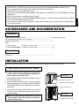
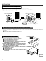
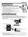
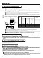
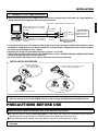
ENGLISH DEUTSCH FRANÇAIS MC-R421U INSTRUCTIONS For Customer Use: Enter below the Model No. and Serial No. which are located at the top of the unit. Retain this information for future reference. Model No. MC-R421U Serial No. This instruction book is made from 100% recycled paper. LST0033-001A Thank you for purchasing the JVC MC-R421U DVD-R DRIVE. Before you start operating this unit, please read the instructions carefully in order to obtain the best possible performance. 1. DANGER: Invisible laser radiation will occur when the unit is open with a failed or defective interlock. 2. CAUTION: Do not open the top cover. There are no user serviceable parts inside the unit; leave all servicing to qualified service personnel. 2 ENGLISH ● The MC-R421U is a DVD-R drive designed for use with the JVC MC-8100U/8200U/8600U "CD/DVD Library". ● It is read compatible with CD-ROM, CD-R, CD-RW, DVD-ROM and DVD-R discs. ● The MC-R421U cannot be operated on its own. ● This drive is not compatible with the MC-1000U/E or MC-2000U series "CD-ROM Library" and MC-7000U series "DVDRAM Library". ● For the compatible discs, see Specifications on page 8. ● When mounting this drive in the MC-8100U/8200U/8600U models, it is required to replace the ROM for the “CD/DVD Library” with the ROM provided with this drive. ● For information on firmware version upgrades and replacement of ROMs, please consult the retailer of the MC-R421U or JVC service agency. ACCESSORIES AND DOCUMENTATION Accessories Drive locking screw (M3 with washer) ............................................................................2 (including one spare) SCSI cable (with a connector cap, 1 m length) ....................................................... 1 Clamp filter (with band) ........................................................................................... 2 ROM For MC-8100U : PLSS1721 (V1-03 or after) ........................................ 1 For MC-8200U/8600U : PLSS1719 (V1-02 or after) ........................................ 2 Documentation Instructions .............................................................................................................. 1 INSTALLATION 䡵 Please refer to the instruction manual of your Library for more information about the CD/DVD Library. 1. How to Open the Door of the JVC Library 䡵 In order to open the door, please refer to the section “HOW TO OPEN THE DOOR DURING OPERATION” in the instructions for the JVC Library. Drive locking screw mounting hole 1. Select the [DOOR OPEN MODE] on the MENU screen of the LCD display section. Drive locking section 2. Press and hold the “SELECT” key for at least five seconds. 3. Turn off the power of the JVC Library when the [THE DOOR CAN BE OPENED] message is displayed on the LCD display section. 4. Insert the key in the key cylinder located at the center of the door and turn it 90 degrees counterclockwise to unlock and open the door. 䡵 Before you start installing the DVD-R Drive, be sure to turn off power of the host computer, all peripheral devices and the Library. • Figure shows the MC-8100U Drive locking section Drive locking screw mounting hole • Figure shows the MC-8200U 3 INSTALLATION 2. How to Open the Drive Storage Cover 䡵 Also be sure to refer to the corresponding sections in the Library instructions. 1. Remove the screws from the drive storage cover that is located at the rear of the Library. 2. Remove the drive storage cover. Drive No.6 • Figure shows the MC-8200U • Figure shows the MC-8100U Drive No.5 Drive No.4 Drive storage section Drive storage section Drive No.3 Drive No.3 Drive No.2 Drive No.1 Drive No.2 Drive No.1 Drive No.4 Screws Screws Drive storage cover Screws Drive storage cover 3. How to Determine the Installation Position of the DVD-R Drive 1. Install the drives from the No.1 to No.6 slots (No. 1 to No. 4 in the case of the MC-8100U) in that order without skipping any drive slots. 䡵 Begin installing drives from the lowest position (No.1). 4. How to Install the DVD-R Drive Drive storage section Sensor slit 1. Insert the DVD-R drive from the rear of the JVC Library. 䡵 Pay attention not to damage the sensor slit. 䡵 Always insert the DVD-R Drive correctly. 䡵 Check that cables connected on the rear of the unit are not caught or pinched when inserting the DVD-R Drive. 2. Insert the DVD-R Drive slowly until the screw installation hole located on the side of the DVD-R Drive and the screw installation hole located on the drive locking section are aligned. 3. Lock the DVD-R Drive in place by using the drive locking screw on the door panel side of the drive. 䡵 Tighten the screw firmly. 䡵 If the drive locking screw is loose, the drive and/or Library could suffer damage. •Beware of damage Drive locking section Drive locking screw 4 INSTALLATION 5. How to Attach the SCSI Cable SCSI cable Blind plate ENGLISH 䡵 If required two SCSI bus channels may be used by adding the provided SCSI cable. If the DVD-R is recorded intermittently due to an insufficiency in the recording transfer rate on the SCSI bus, the recording quality may deteriorate and playback malfunctions may occur. 1. While holding the two blind plates, remove the four screws on the SCSI connector installation section at the rear of the JVC CD/DVD Library in order to remove the two blind plates. I-D SCS I-C SCS 2. Insert the provided SCSI cable through the installation hole from the back side of the rear panel and secure it with the four screws. 䡵 Remove the connector cap of the SCSI cable for installation. 䡵 Be sure that the SCSI connector is inserted in the correct direction. (It should be the same as the direction of the SCSI connector “SCSI-A”.) I-B SCS I-A SCS Connector cap 3. If you are not connecting the SCSI cable to the OUT side of the SCSI connector “SCSI-D”, place the connector cap over it. 6. How to Connect Cables to the DVD-R Drive 䡵 Also refer to the corresponding sections in your Library Instructions Manual. 1. Connect the power supply cable, control cable and SCSI cable to the connectors at the rear of the DVD-R Drive. 䡵 When using the MC-8100U, the No. of the cable must always correspond to the No. of the drive bay to which it is being connected. If the cable with the wrong number is connedted, it will lead to the equipment malfunctioning. 䡵 When using the MC-8200U/8600U, connect power supply and control cables, which lead from the side of the DVD-R 3 drive bay to the drive. 䡵 Insert all connectors firmly. Control cable Rear section of the DVD-R Drive 1 14p Slide switch N W DIP switch 2 4p Power cable 3 Connection example of a SCSI cable SCSI cable Internal SCSI cable (additional) • Up to two DVD-R drives can be connected (Terminate here ) DVD-R Drive (Terminate here ) DVD-R Drive DVD-R Drive Library SCSI board SCSI connector SCSI-D(F) SCSI-C(E) SCSI-B SCSI-A OUT 2 IN 2 OUT 1 IN 1 Connect an active terminator. To be connected with host computer's SCSI host adapter No.2 Connect an active terminator. To be connected with host computer's SCSI host adapter No.1 Internal SCSI cable (Standard) • Up to 6 drives can be connected (• Up to 4 drives in the case of MC-8100U) 䡵 SCSI cables should be connected as a daisy chain connection. Each connector may be connected to the drive positions as illustrated in the diagram. 䡵 Terminate the physical end of the SCSI bus. For information on how to set the built-in terminator, refer to the item 1 “TERM” of “7. How to Set the DIP and Slide Switches”. For an external terminator we recommend that an active SCSI terminator is used with the JVC CD/DVD Library. 5 INSTALLATION 7. How to Set the DIP and Slide Switches 䡵 Always turn OFF the power of Library when you set the dip switch modes. 1. TERM This selects the use of the built-in terminator. 䡵 Terminate the SCSI bus at the position where it physically terminates. 䡵 When using the built-in terminator, set the TERM for the drive located at the physical end of the SCSI bus to ON, and the TERM for the other drives to OFF. 䡵 When not using the built-in terminator, attach an external terminator to the OUT side of the SCSI connector. 䡵 When using an external terminator, set TERM of all the drives to OFF. 䡵 To improve the stability of SCSI bus communications, it is recommended to use an active external terminator. ID 0 ID 1 ID 2 TERM 2. ID2 3. ID1 This sets the SCSI ID No. on the drives. 4. ID0 ON W ON OFF N 1 2 3 4 (Factory setting) W N Switch SCSI ID No. ID2 ID1 ID0 0 OFF OFF OFF 1 OFF OFF ON 2 OFF ON OFF 3 OFF ON ON 4 ON OFF OFF 5 ON OFF ON 6 ON ON OFF 7 ON ON ON Remarks Default factory setting 䡵 Set the SCSI ID No. between 0 - 7 using only a ID No. that is not being used by other SCSI devices. 䡵 Note that the default SCSI ID of the Library is 0 and the SCSI card is 7. 䡵 For the details on default factory settings, please refer to the section “SCSI ID No. SETTING” of the instructions for the JVC Library. 䡵 Be sure to set the slide switch to N for use. (The position W is provided for use in servicing.) 8. How to Reattach the Drive Storage Cover 䡵 Always reattach the drive storage cover before switching ON the JVC Library. 1. Fasten the panel with the screws that were removed in procedure ( refer to “2. How to Open the Drive Storage Cover” on page 4). 9. How to Close and Lock the Door of the JVC Library 䡵 Always close and lock the door before switching ON the JVC Library. 1. Close the door and lock the key cylinder. 10. Automatic Drive Detection Mode 䡵 Please also refer to the corresponding sections in the CD/DVD Library instructions. 䡵 If using the CD/DVD Library MC-8100U/8200U/8600U, be sure to execute the auto drive detection mode after installing, adding, exchanging or removing drives, to prevent any malfunction. 1. While holding the “8” key on the control panel, turn on the power of the Library. 2. When the LCD display shows “DRIVE DETECTION COMPLETED”, turn off the power of the Library. 3. Turn the Library on again. 䡵 The DRIVE DISPLAY of the CD/DVD Library displays this drive as a “DVD-RAM”. 䡵 Before you install, add, remove or replace drives, and/or change the SCSI ID No., turn OFF the power of the host computer. Remember to turn it ON again after completing the necessary operations. 6 INSTALLATION 11. Example of a SCSI Cable Connection 䡵 When interconnecting the JVC CD/DVD Library and the host computer with a SCSI cable, use a high-impedance, shield cable with two clamp filters fitted near both connectors. External SCSI cable to host computer's SCSI host adapter No.2 for controlling the Library Host computer External SCSI cable to host computer's SCSI host adapter No. 1 for controlling the Library To “SCSI-C” connector ENGLISH SCSI cable (of high impedance, shielded design) Attach the active terminator to the OUT connector. To “SCSI-A” connector CD/DVD Library ● An operational error may occur when the total length of the internal and external SCSI cables exceed 3 meters (with SCSI-2, 10 Mbytes/sec. sync). When the SCSI bus is used as SCSI-2, 5 Mbytes/sec. async, the total length of the cables can be extended to up to 6 meters. ● Regarding the length of the provided SCSI cable is approx. 1 m (3.3 feet). ● The length of the SCSI cable inside the JVC CD/DVD Library refer to “CONNECTING SCSI CABLES AND POWER CORD” in the operation manual for the main unit. ● Be sure to lock the connectors of the external SCSI cable once they are connected. INSTALLATION PROCEDURE 2 Press the clamp filter against the connector Tighten until the dabs are completely locked. and fasten it with a provided band. Pull the band tightly. Cut off any extra length. 1 Fit the clamp filter around the cable. 䡵 Signal disturbance may occur if a high-impedance, shielded SCSI cable is not used. Also, the above clamp filters are necessary for the JVC CD/DVD Library in order to comply with EMI Standard ‘EN55022 Class A’. PRECAUTIONS BEFORE USE 䡵 Read the following before installing this drive in your Library for the first time. 䡵 To mount this drive on the MC-8100U/8200U/8600U in your Library, the firmware of the CD/DVD Library should be upgraded. Please change the ROM in the CD/DVD Library to the ROM provided with this drive. 䡵 For the ROM replacement method, consult your dealer or nearest JVC-authorized service agent. 䡵 Do not set the Power switch of the CD/DVD Library to ON until all of the work described above has been completed. 7 SPECIFICATIONS Interface Data transmission rate : SCSI-2 : Sustained (When the host adapter is set to the maximum sync transfer rate of 20 Mbytes/sec.) DVD-R for General (Single-sided 4.7 GB or double-sided 9.4 GB, recordable): 3.31 Mbytes/s to 5.75 Mbytes/s DVD-ROM (Single Layer), DVD-R for General (Single-sided 4.7 GB or double-sided 9.4 GB, playback) 3.44 Mbytes/s to 5.78 Mbytes/s (6X max., CAV) DVD-RAM (Ver. 2.1, single-sided 4.7 GB, double-sided 9.4 GB, playback only): 2.77 Mbytes/s DVD-RAM (Ver. 1.0, single-sided 2.6 GB, playback only): 1.38 Mbytes/s CD-ROM/-R (Playback only): 1.5 Mbytes/s to 3.6 Mbytes/s (24X max., CAV) CD-RW (Playback only): Max. 1.8 Mbytes/s (12X max., CAV) Burst Max. 8 Mbytes/sec. (async transfer) Max. 10 Mbytes/sec. (sync transfer) Average access time (1/3 stroke, typ.) Buffer capacity Additional write count (DVD-R for General 4.7 GB) Accessories Operating environment Dimensions Weight Applicable discs : DVD-R for General 4.7 GB : 100 ms DVD-ROM (Single Layer) : 100 ms DVD-RAM (4.7 GB) : 135 ms DVD-RAM (2.6 GB) : 155 ms CD-ROM : 95 ms The above values were measured using JVC's measurement method. : 1 Mbyte : Max. 100 times (per disc side) (Assuming that each disk drive insertion/ejection cycle is counted as one time) : SCSI cable (with a connector cap, 1 m length) ..................... x 1 Clamp filter (with band) ......................................................... x 2 ROM ...................................................................................... x 3 Drive locking screw ............................................................... x 2 : Temperature : 5˚C to 35˚C Humidity : 10% to 80% (without condensation) : 171 mm x 47.5 mm x 240 mm (WxHxD) : 1.5 kg : DVD-R for General 4.7 GB Recommended discs (Single-sided 4.7 GB): Panasonic LM-RF47 Panasonic LM-RS47B50 (Spindle type, 50-disc pack) Verbatim 094077 Verbatim 094058 (Spindle type, 50-disc pack) Maxell DR47.1P Maxell DR47.50S (Spindle type, 50-disc pack) Recommended disc (Double-sided 9.4 GB): Verbatim 094171 (Spindle type, 50-disc pack) Maxell DR94.50S (Spindle type, 50-disc pack) DVD-R 3.95 GB (Ver. 1.0, disc at once, playback only) DVD-ROM DVD-RAM (Ver. 2.1, single-sided 4.7 GB, double-sided 9.4 GB, playback only) DVD-RAM (Ver. 1.0, single-sided 2.6 GB, playback only) CD-ROM (Mode 1, Mode 2, etc.) CD-R (Playback only) CD-RW (Playback only) * Note 1 : With the DVD-R, DVD-RAM, CD-R and CD-RW, the full performance may not be evident depending on the write condition. * Note 2 : Only the discs with a diameter of 120 mm are applicable. 䡵 The specifications and appearance of this unit are subject to change without notice. 8 MC-R421U DVD-R DRIVE VICTOR COMPANY OF JAPAN, LIMITED © 2001 VICTOR COMPANY OF JAPAN, LIMITED is a registered Trademark owned by VICTOR COMPANY OF JAPAN, LTD. is a registered Trademark in JAPAN, the U.S.A., the U.K. and many other countries. Printed in Japan LST0033-001A