1
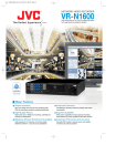
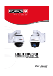
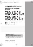
VR-N1600_Startup_EN_001B.book Page 1 Thursday, August 20, 2009 1:10 PM
NETWORK VIDEO RECORDER
VR-N1600U
VR-N1600E
STARTUP GUIDE
(A)
WARNING
LIVE/BROWSE
㧝
㧞
㧟
㧠
SELECT
㧡
㧢*1/'
㧣
㧤
PTZ/PRESET
㧥
ALARM
OPERATE
REV
FWD
HDD
LOCK
REC CONTROL
FUNCTION
SERIAL
CANCEL
ZOOM OUT
ZOOM IN
SEARCH
KEY
ALARM CLEAR
REC/STOP
STOP(PB)
PLAY
SKIP
Powered by Milestone
Please read the following before getting started:
Thank you for purchasing this JVC product.
Before operating this unit, please read the instructions
carefully to ensure the best possible performance.
For Customer Use:
Enter below the Serial No. which is located on the
body.
Retain this information for future reference.
Model No.
VR-N1600U
Serial No.
\
LST0601-001B
VR-N1600_Startup_EN_001B.book Page I Thursday, August 20, 2009 1:10 PM
IMPORTANT SAFEGUARDS
I
VR-N1600_Startup_EN_001B.book Page II Thursday, August 20, 2009 1:10 PM
SAFETY PRECAUTIONS (for USA)
II
VR-N1600_Startup_EN_001B.book Page III Thursday, August 20, 2009 1:10 PM
SAFETY PRECAUTIONS (for Europe)
III
VR-N1600_Startup_EN_001B.book Page IV Thursday, August 20, 2009 1:10 PM
IV
VR-N1600_Startup_EN_001B.book Page V Thursday, August 20, 2009 1:10 PM
SICHERHEITSVORKEHRUNGEN (for Germany)
V
VR-N1600_Startup_EN_001B.book Page VI Thursday, August 20, 2009 1:10 PM
VI
VR-N1600_Startup_EN_001B.book Page VII Thursday, August 20, 2009 1:10 PM
SICHERHEITSVORKEHRUNGEN (for Germany)
VII
VR-N1600_Startup_EN_001B.book Page VIII Thursday, August 20, 2009 1:10 PM
E
1600E
E
1600E
E
E
VIII
VR-N1600_Startup_EN_001B.book Page 2 Thursday, August 20, 2009 1:10 PM
Getting Started
Features
Motion Detect
Enables recording to start automatically when AmotionB is
detected in the preset live image. You can also specify the
detection area for each camera.
Automatic detection of network cameras
Reduces the hassle of complex camera registration
procedures.
Built-in large-capacity hard disk (500 GB)
HDD expansion supported
Addition of up to 500 GB (built-in), 2 TB x 2 units (external.)
RAID1 supported
Supports RAID1 if additional built-in HDD is installed.
Writing the same data to two separate hard disks (mirroring)
to enable normal use if one of the hard disks breaks down.
Simultaneous recording up to 16 channels at 160
ips
Simultaneous recording up to 16 channels at 240 ips is
possible when the NVR Viewer is not started up.
In addition, purchasing additional camera licenses enables
the VR-N1600U/E(A) to handle simultaneous recording up to
32 channels.
For details, please consult your nearest JVC dealer.
Alarm Mail Notification
Enables notification by e-mails to be sent out when an alarm
or motion is detected.
How to Read this Manual
䡵 VR-N1600U/E Documents
There are two documents on this unit.
(1) Startup Guide
This is a booklet that is supplied together with
VR-N1600U/E. It is also available in the PDF file
format. You can find it in the CD-ROM provided.
(2) Instruction Manual (PDF)
This manual is available in the PDF file format. You can
find it in the CD-ROM provided.
䡵 Symbols Used in this Manual
Note
Precautions to take during operation of this
unit.
Memo
Details for reference, such as functions and
restrictions on uses.
A
Page or item to refer to.
䡵 Content of this Manual
Display/Distribution performance at 80 ips
(VR-N1600U/E) and 160 ips (VR-N1600U/E(A))
Enables simultaneous recording and playback
Playback of recorded images, jog dial playback and skip
playback are possible while recording is in progress.
Direct Search
Enables you to retrieve data of a specific date/time or alarm
position speedily.
Power failure recovery record
If a power failure occurs during recording, the system
resumes recording in the mode selected before the power
failure after recovery.
Alarm recording
Enables recording to start automatically in the alarm
recording mode when alarm signal input is received during
recording.
2
● The copyright of this manual belongs to JVC.
Reproduction or copy of this manual, in part or in
whole, without the prior consent of JVC is strictly
prohibited.
● Product names used in this manual are the trademarks
or registered trademarks of the respective companies.
Symbols such as 姠, 姞, 姝 and are omitted in this
manual.
● Milestone and XProtect Enterprise are the registered
trademarks of Milestone Systems, Inc.
● Designs, specifications and other details used in this
manual may be modified for improvement without prior
notice.
This STARTUP GUIDE deals only with the initial setup and
basic operational procedures on the VR-N1600U/E.
Besides the STARTUP GUIDE, the VR-N1600U/E
INSTRUCTIONS is also provided on a CD-ROM that
explains further details on the operation procedures.
For details, please refer to the CD-ROM.
VR-N1600_Startup_EN_001B.book Page 3 Thursday, August 20, 2009 1:10 PM
Contents
Getting Started
Features ............................................................................ 2
Contents ............................................................................ 3
Precautions for Proper Use of this Product ....................... 4
Part Names and Functions ................................................ 6
Mounting to a Rack ......................................................... 10
Preparation
System Connection Example .......................................... 11
During Initial Startup ....................................................... 12
Basic Operation
Viewing Live Images via Front Panel Control .................. 16
Displaying the [Live] Screen ........................................ 16
Select a View ............................................................... 16
Select a Camera .......................................................... 16
Operating the Camera ................................................. 17
Playing Back Recorded Images
via Front Panel Control .............................................. 18
Select a View ............................................................... 18
Searching Recorded Image
Using a Specific Date/Time .................................... 18
Playing, Skipping and Stopping Recorded Images ...... 18
Adjusting the Playback Speed
(Jog/Shuttle Playback) ........................................... 19
Others
Troubleshooting ............................................................... 20
Specifications .................................................................. 21
3
VR-N1600_Startup_EN_001B.book Page 4 Thursday, August 20, 2009 1:10 PM
Getting Started
Precautions for Proper Use
of this Product
䢇
Locations of Storage and Use
䢇 Do not store the unit at the following places.
Doing so may cause the unit to malfunction or break
down.
● Hot or cold places beyond the allowable operating
temperature (5 I to 40 I)
● Humid places beyond the allowable operating humidity
(30%RH to 80%RH) (no condensation)
● Places that emit a strong magnetic field, such as near
transformers and motors
● Places near devices that emit radio waves, such as
transceivers and mobile phones
● Places with considerable dust and sand
● Places with strong vibrations
● Places where water droplets may be formed, such as
window sides
● Places with considerable vapor and oil, such as
kitchens
● Places that emit radiation, X-rays, and corrosive gases
䢇 Using this unit and the cable that is connected to it near
places where strong radio waves or magnetic fields (such
as near radios, TVs, transformers, and monitors) are
emitted may cause noises in the video images or color
changes.
Handling Precautions
䢇 Do not stack the devices on one another during use.
Heat and noise from the devices may cause the unit to
malfunction or break down, and lead to fire.
䢇 Do not block the ventilation holes.
Doing so may cause heat to trap inside the unit and result
in fire. Do not use this unit by laying it down sideways,
upside down, or at an angle.
䢇 Do not place objects on this unit.
Placing heavy objects, such as TV monitors, or objects
that are bigger in size on this unit may cause it to lose
balance and drop or fall, hence resulting in injuries.
䢇 Do not stand or sit on this unit.
Doing so may cause this unit to fall or break down, and
result in injuries. Keep it out of the reach of young
children.
䢇 Do not place objects with water (e.g., vases, flower pots,
cups, cosmetic products, and chemicals) on this unit.
Water may enter this unit and result in fire or electric
shock.
䢇 Do not insert objects into this unit.
Metallic or other flammable objects that enter this unit
from the ventilation holes may result in fire or electric
shock.
Precautions for Handling Hard Disk Drive
䢇 The distance between the head and the disk is only about
0.02 m when the hard disk (henceforth HDD) is reading
the data. Vibration or impact that is exerted on the HDD
may therefore cause the head to hit against the disk,
hence causing the disk surface to dent or the disk to chip.
When this occurs, data may not be properly read, or in a
worse scenario, continued use in this condition may result
4
䢇
䢇
䢇
䢇
in head crash (damage). Careful attention must therefore
be paid when handling it.
Precautions During Installation and Change of Installation
Location
Moving of this unit or installation work is strictly prohibited
when the power of this unit is on or immediately after the
power is turned off (approximately 1 minute). (The HDD
continues to move under its own inertia for some time
after the power is disconnected, and exertion of vibration
or impact during this interval may result in HDD failure.)
When moving this unit, wrap it using cushioning materials
to protect it from external shock.
Handling Precautions
● Handle this unit carefully without exerting vibration or
impact on it.
● Do not remove the power plug during recording or
playback, or when the HDD is being accessed.
● The HDD is a consumable product. Perform
maintenance after it has been used for about 18,000
hours. (This value is based on its use in an
environment with a temperature of 25 I, and may vary
according to the environment of use.) For inquiries on
maintenance plans and expenses, consult your nearest
JVC dealer listed on the separate sheet.
When installing an external hard disk, we recommend the
use of UPS (uninterruptible power supply) to ensure the
stable operation of the system.
Power failure that occurs during formatting or
disconnection of the HDD may affect its subsequent use
even when the UPS is connected.
JVC shall not be held responsible for the compensation of
losses incurred in the event that recording or playback
fails due to defects in this unit or its hard disk drive.
● Images recorded on the HDD will be deleted when you
replace it with a new disk. Note also that recorded
images may be deleted when you upgrade the software
for this unit.
VR-N1600_Startup_EN_001B.book Page 5 Thursday, August 20, 2009 1:10 PM
Precautions when Moving this Unit
䢇 Remove all connected cords before moving
Turn off the power and remove the power plug before
moving this unit. Failure to do so may cause damage on
the cords, and result in fire or electric shock.
䢇 Moving of this unit or installation work is strictly prohibited
when the power of this unit is on or immediately after the
power is turned off (approximately 1 minute).
The HDD continues to move under its own inertia for
some time after the power is disconnected, and exertion
of vibration or impact during this interval may result in
HDD failure.
䢇 When moving this unit, wrap it using cushioning materials
to protect it from external shock.
䢇 Handle this unit carefully without exerting vibration or
impact on it.
Precautions for Handling Power Cords
䢇 Do not use the supplied cords on devices other than this
unit.
䢇 Do not place heavy objects on the power cord, or place it
under this unit
Doing so may cause damage on the cords, and result in
fire or electric shock.
䢇 Do not use cords other than those supplied with this unit
Use only power cords supplied together with this unit.
Using cords with different withstanding voltage
specifications or damaged cords may result in fire or
electric shock.
䢇 Do not remove the power plug during recording or
playback, or when the HDD is being accessed.
Maintenance
䢇 Eliminate static electricity before performing work that
requires you to touch the input/output terminals, such as
when installing devices.
䢇 Do not touch the rear panel of this unit when it is running
as static electricity may cause it to malfunction.
䢇 When there is a large number of data recorded on this
unit, such as short alarm records, a longer time may be
required during search or backup. This is not a
malfunction.
䢇 Data recorded from TV broadcasts or video (audio)
recordings shall only be restricted to personal uses, and
their use without the prior consent of the copyright holder
is strictly prohibited under the copyright law.
䢇 The width of the border lines (black in color) of images on
the split screen varies according to the type of input
signals. This is due to the characteristics of the camera’s
input signals, and is not a malfunction. The condition may
also be improved by adjusting this unit. For details, consult
your nearest JVC dealer.
䢇 This unit comes with a high-precision hard disk device. Be
careful not to exert vibration or impact on this unit when
handling it.
䢇 Exertion of vibration or impact particularly when the power
is on or when the hard disk is being accessed may cause
this unit to break down.
䢇 When moving this unit, do so about 1 minute after
disconnecting the power supply.
䢇 Do not turn off the power switch at the rear of this unit or
unplug the power cord during recording or playback, or
when the hard disk is being accessed. Otherwise, it may
break down.
When this device is used as a general household,
there is a possibility of radio disturbance to the
radio and television receiver etc.
䢇 Turn off the power before performing maintenance of this
unit.
䢇 Wipe this unit using a soft cloth. Wiping using thinner or
benzene may cause the surface to melt or fog. When the
surface is extremely dirty, wipe using a cloth that is dipped
into a neutral detergent diluted with water, followed by
wiping with a dry cloth.
Energy Conservation
䢇 Turn off the power of the system for safety reasons and to
save energy if this unit is not to be used for a long time.
Copyright
䢇 Use of video or audio sound recorded using this unit for
commercial purposes or playing them for public viewing or
listening may be an infringement of the copyrights of their
respective authors under the copyright law.
䢇 These video (audio) recordings shall only be restricted to
personal uses, and their use without prior consent of the
copyright holder is strictly prohibited under the copyright
law.
Others
䢇 When there is variation in the supply voltage such as
during lightning, operation of this unit may be disabled to
protect the system until the supply voltage stabilizes
again.
5
VR-N1600_Startup_EN_001B.book Page 6 Thursday, August 20, 2009 1:10 PM
Getting Started
Part Names and Functions
Front
S
T
R
Q
WARNING
A
B
LIVE/BROWSE
㧝
㧞
㧟
㧠
SELECT
㧡
㧢*1/'
㧣
㧤
PTZ/PRESET
㧥
ALARM
OPERATE
REV
FWD
O
LOCK
REC CONTROL
FUNCTION
SERIAL
CANCEL
ZOOM OUT
ZOOM IN
ENTER
P
HDD
SEARCH
KEY
ALARM CLEAR
REC/STOP
STOP(PB)
PLAY
SKIP
CD E
F GHIJ K L M
A [OPERATE] Button/Indicator
Switches operation on or off. Press the button to turn operation
AONB and hold down the button to turn operation AOFFB. The
indicator blinks while the recorder is starting up or shutting down.
B [REC CONTROL] Button/Indicator
Switches the recording control mode on or off. The indicator lights
up when the recording control mode is set to on.
Press and hold the [FUNCTION] button, and press the [REC
CONTROL] button at the same time to display the menu.
Memo :
● The main menu cannot be displayed in the recording control
mode or during recording.
● The recording control mode performs recording in accordance
with the settings in the [Camera Record Setting] menu.
C [SELECT] Button/Indicator
Use the S key to set to the camera selection mode. The indicator
lights up when the camera selection mode is set to on.
D [PTZ/PRESET] Button/Indicator
Switches between the PTZ mode and PRESET mode of the S key.
The mode changes each time the button is pressed. The indicator
lights up when PTZ mode is selected and blinks when PRESET
mode is selected.
E [SERIAL] Terminal
For connecting the communication control terminals on a mouse
(sold separately), flash memory (sold separately) or UPS (sold
separately).
Memo :
● Use the [SERIAL1 to 4] port on the rear panel for additional hard
disk drive connection. (A Page 8)
Note :
● Attach the serial port cover supplied when the port is not in use.
● Static electricity may cause the unit to malfunction. Remove any
static electricity before starting operation.
F Status indicators
䡵 [WARNING] Indicator
Lights up when an error occurs. (A Page 20)
Press and hold the [ALARM CLEAR] button to turn off the light.
6
N
䡵 [ALARM] Indicator
Lights up when an alarm is activated.
Goes off when the [ALARM CLEAR] button is pressed.
䡵 [HDD] Indicator
Lights up when the built-in hard disk drive is accessed.
䡵 [LOCK] Indicator
Lights up when operation is locked.
G [FUNCTION] Button
Press the following buttons while holding down the [FUNCTION]
button to use the following features.
[FUNCTION]
+[OPERATE]
Press and hold to forcibly shut down
the system.
[FUNCTION] +[REC
CONTROL]
Displays the main menu.
[FUNCTION] +[LIVE/
BROWSE]
Reboots the NVR Viewer and the
internal distribution server.
Press and hold to log out.
[FUNCTION] +[5]
For controlling the PTZ camera.
[FUNCTION] +[6]
Displays the maintenance information
screen.
[FUNCTION] +[8]
Sets whether to display the HDD
meter or not.
H [SEARCH] Button
Displays the date and time search screen when in the playback
mode. (A Page 18)
I [KEY] Button
Press to display or hide the Asoftware keyboardB.
Memo :
● Use the software keyboard to input characters.
J [ALARM CLEAR] Button
Clears the [ALARM] display when an event occurs or motion is
detected. Press and hold this button to turn off the [WARNING]
indicator.
K [REC/STOP] Button
Press to start recording in all cameras. (When in the recording
control mode, pressing this button exits the recording control mode
and starts recording on all cameras.) To stop recording, press and
hold the button.
VR-N1600_Startup_EN_001B.book Page 7 Thursday, August 20, 2009 1:10 PM
When in the recording control mode, press and hold this button to
exit the recording control mode.
Memo :
● The manual recording mode executes recording from all
cameras regardless of the settings in the [Camera Record
Setting]. Recording is carried out in accordance with the frame
rate selected in [Camera Record Setting].
L [STOP(PB)] Button
Stops playback when you press this button in the playback mode.
M [PLAY] Button
Plays back at the speed and in the direction specified by the Shuttle
Dial position.
N [SKIP] Button
䡵 [S]
Press to move the item selection in the reverse direction in the
menu or settings screen. Jumps to the beginning of the previous
sequence on the selected camera when you press this button in the
playback mode. Press and hold it to jump to the first image in the
database of the selected camera.
䡵 [T]
Press to move the item selection in the forward direction in the
menu or settings screen. Jumps to the beginning of the next
sequence on the selected camera when you press this button in the
playback mode. Press and hold it to jump to the last image in the
database of the selected camera.
Memo :
● “Sequence” indicates a certain block of images that are recorded
during motion detection.
● Recorded images are stored in the database. “Database” refers
to data recorded in this unit.
O Jog dial
Plays back a single frame when it is rotated in the playback mode.
P Shuttle dial
The position of the dial specifies the playback speed and playback
direction when in the playback mode. Playback speed is selectable
from x 1/20, x 1/5, x 1, x 2, x 5, x 10 and x 20 according to the
angle.
Q [REC] Indicator
Lights up during recording. Flashes during EMERGENCY or EXT
REC IN recording.
● PTZ keypad mode (live image display screen only)
Moves the camera in the direction indicated by the arrow. ([1/
][2/D] [3/ ][5/C][7/B] [9/ ][10/0/E] [11/ ])
Use the [6/HOME] button to move the camera to the home
position.
● Preset keypad mode (live image display screen only)
For selecting the preset position. ([1] to [9]. 10 to 19 can be
selected when [10/0/E] is pressed at first.)
䢇 During search for recorded images
For narrowing down the search using a date, month, week, or
time.
● (Enter number using [1] to [10/0] buttons. A0B is input when
[10/0] button is pressed.)
䢇 During display of software keyboard
● Selection keypad mode
For entering numeric characters. (A0B is input when the [1/ ]
to [10/0/E] and [10/0/E] buttons are pressed.)
● PTZ keypad mode (live image display screen only)
Moves the mouse pointer in the direction indicated by the
arrow. Press [1/ ][2/D] [3/ ][5/C][7/B] [9/ ][10/0/E] [11/ ] or
[6/HOME] to move to the center of the screen.)
[13/CANCEL]
䢇 Setting screens on the main menu
Cancels the selection.
[14/ZOOM OUT]
䢇 Live image display and recorded image playback screens
● PTZ keypad mode (live image display screen only)
Zooms out.
● Preset keypad mode
For selecting the next view.
● Press the [14/ZOOM OUT] button while holding down the
[FUNCTION] button to change the resolution of VGA output.
[15/ZOOM IN]
䢇 Live image display and recorded image playback screens
● PTZ keypad mode (live image display screen only)
Zooms in.
● Preset keypad mode
For selecting the previous view.
● Press the [15/ZOOM IN] button while holding down the
[FUNCTION] button to change the resolution of VGA output.
[16/ENTER]
S Keypad buttons/Indicator
䢇 Setting screens on the main menu
Confirms the selection.
䢇 During display of software keyboard
To perform the mouse click operation.
[0] to [16]
T [LIVE/BROWSE] Button/Indicator
䢇 Login screen
● For entry of passwords (numeric characters). (Enter number
using [1] to [10/0] buttons. A0B is input when [10/0] button is
pressed.)
䢇 Setting screens on the main menu
● PTZ mode Keypad
For selecting a menu item. ([2/D], [10/0/E])
● Camera selection keypad mode
● For entering numeric characters. (Enter number using [1] to
[10/0] buttons. A0B is input when [10/0] button is pressed.)
䢇 Live image display and recorded image playback screens
● Camera selection keypad mode
For selecting a camera number. Upon selecting, the indicator
corresponding to the selected camera input lights up.
Switches between the [Live] mode and [Browse] mode.
The indicator lights up when in the [Live] mode.
Pressing the [LIVE/BROWSE] button when the wallpaper screen is
displayed shows the [Live] screen.
Press and hold the [FUNCTION] button, and press the [LIVE/
BROWSE] button at the same time to reboot the NVR Viewer and
the internal distribution server.
Press and hold the [FUNCTION] button, and press the [LIVE/
BROWSE] button at the same time to log out of the system.
R Center panel
Do not remove the cover.
Memo :
● When [Auto Logon] is enabled, the login operation starts
automatically immediately after logging out.
7
VR-N1600_Startup_EN_001B.book Page 8 Thursday, August 20, 2009 1:10 PM
Getting Started
Part Names and Functions
(continued)
Rear Panel
d
POWER
U
ON
OFF
V
W
X YZ a
b
c
U [POWER] switch
a [SERIAL1 to 4] serial terminals 1 to 4
Switches the power on or off.
For connecting the communication control terminals on a
mouse (sold separately), flash memory (sold separately),
UPS (sold separately) or additional disk drive (sold
separately).
Memo :
● Be sure to press and hold down the [OPERATE] button on
the front panel to shut down the system before switching
off the power supply.
V [AC IN] power input terminal
b [LAN2] LAN2 connection terminal (Intranet)
For connecting to the remote PC network using a LAN cable.
Color
Connect to an AC outlet using the power cable supplied.
W [AUDIO IN 1/AUDIO IN 2] audio input terminals 1/2
(RCA)
Left
Indicator
Connect to the audio output terminal of the device from
which audio signals are to be recorded.
X [AUDIO OUT] audio output terminal (RCA)
Outputs live sound in the live viewing mode.
Outputs recorded sound in the playback mode.
Memo :
● There is no audio output when playing back still images,
when running searches other than x1, or when playing
back frame-by-frame.
Right
Indicator
Status
Off
Communication at 10 Mbit/
second.
Green
On
Communication at 100 Mbit/
second.
Orange
On
Communication at 1 Gbit/second.
Yellow
Off
Not connecting to the network.
Blinking
Communication is in progress.
c Connector cover
Memo :
● Do not remove the cover.
d Signal input/output terminals
Y [VGA OUT] VGA output terminal
Outputs live images, recorded images and the menu
screens.
Z [LAN1] LAN1 connection terminal (camera
network)
For connecting to the IP camera (sold separately) network
using a LAN cable.
Color
Left
Indicator
Green
Orange
Right
Indicator
8
Yellow
Status
Off
Communication at 10 Mbit/
second.
On
Communication at 100 Mbit/
second.
On
Communication at 1 Gbit/second.
Off
Not connecting to the network.
Blinking
Communication is in progress.
For operating VR-N1600U/E using external alarm signals or
signals received from external devices, or for operating
external devices by outputting signals.
Memo :
● Diameter of applicable cables: AWG22 to AWG28
VR-N1600_Startup_EN_001B.book Page 9 Thursday, August 20, 2009 1:10 PM
Rear I/O Terminals
e
fhjl n
gikm o
ON
OFF
p
䡵 Input ports
䡵 Output ports
e [ALARM IN 1 to 8] alarm input terminals 1 to 8
j [COMMON] signal ground terminal
Alarm recording is activated when signals are input to these
terminals.
This is a common ground terminal. Connect it to the signal
ground terminal on the connected device. (This can be used
when there are insufficient common ground terminals.)
f [EMERGENCY] emergency input terminal
Recording is activated in all cameras when a signal is input
to this terminal.
k [ALARM OUT] alarm output terminal
Outputs a signal when recording is started by an alarm.
g [ALARM RESET] alarm reset input terminal
l [WARNING OUT] warning output terminal
Output from the alarm output terminal is stopped when a
signal is input during output of the Alarm Out signals.
Turns off the [ALARM] indicator F on the main unit. Press
and hold the button to turn off the [WARNING] indicator F on
the main unit.
Outputs a signal when an error such as operation
abnormality occurs on the hard disk.
h [EXT REC IN] external recording input terminal
n [OPTION OUT1][OPTION OUT2] OPT OUT
Recording in all cameras is started or stopped by an external
signal. Recording will not be started in cameras to which no
video signal is being input.
i [OPE ON/OFF] Operate ON/OFF terminal
Switches between OPERATE ON or OFF when a signal is
input.
m [REC TALLY] recording status output terminal
Outputs the recording status of this unit.
output terminals 1/2
Outputs a signal when an event is detected.
o [COMMON] signal ground terminal
Same as j.
p [SIGNAL GND] signal ground terminal
This is a common ground terminal. Connect it to the signal
ground terminal on the connected device.
(This can be used when there are insufficient common
ground terminals.
Memo :
● Do not use this terminal for protective earthing.
9
VR-N1600_Startup_EN_001B.book Page 10 Thursday, August 20, 2009 1:10 PM
Getting Started
Part Names and Functions
(continued)
Rear I/O Terminals
Use the supplied rack mount bracket to mount VR-N1600U/E
to the EIA rack.
Terminal
e[ALARM
IN]
Remarks
250 ms
and above
250 ms
and above
Make
Break
Make
Contact
Input
1 Mount the rack mount bracket using screw (1)
● Use the 4 screws (M4 x 10 mm) supplied to fasten
VR-N1600U/E at the two sides.
2 Remove screws B of the foot (4 pcs) at the
bottom
Memo :
● Remove the foot.
● Set the impedance at the output
end to 10kK or below.
f[EMERGENCY]
g[ALARM
RESET]
Mounting to a Rack
3 Mount to the rack using screws C
Make
Contact
Input
● Use the 4 screws (M5 x 11 mm) supplied to fasten this
unit to the rack.
250 ms
and above
Memo :
● Set the impedance at the output
end to 10kK or below.
h[EXT REC
IN]
Make
Contact
Input
250 ms
and above
Memo :
Rack Mount
Bracket
● Set the impedance at the output
end to 10kK or below.
j[OPE ON/
OFF]
Make
Contact
Input
1 s and
above
OPE ON
(4 Locations)
Approx. 50 ms
OPE OFF
Memo :
● Set the impedance at the output
end to 10kK or below.
j[REC
TALLY]
k[ALARM
OUT]
l[WARNING OUT]
m[OPTION
OUT1]
[OPTION
OUT2]
10
Make
Output In
Progress
Break
Output In
Progress
(External Pull-up Level)
The make contact is formed using
the individual output terminals and
the COM terminal. Turning off the
power of VR-N1600U/E switches the
output of the output terminals to
break.
Note :
Auto
Collector
Output
(DC15V, 10
mA and
below)
● Do not place any object on the VR-N1600U/E unit that
has been mounted to the rack. Doing so may cause it to
lose balance and drop or fall, hence resulting in injuries or
damages.
● When mounting 2 or more units of VR-N1600U/E to the
rack, make sure to mount it at a distance that is at least
equivalent to one unit.
VR-N1600_Startup_EN_001B.book Page 11 Thursday, August 20, 2009 1:10 PM
Preparation
System Connection
Example
The following operations are possible with this system.
● Surveillance (live image, recording and playback) by connecting up to 16 cameras
● Checking recorded images on the VGA monitor
● Recording/Playing sound
● Alarm recording
● Remote surveillance using PCs
Microphone
Speaker (with built-in amplifier)
AUDIO OUT
AUDIO IN
ALARM IN/OUT
ALARM IN/ALARM OUT
Mic Amp
ON
Supplied power cable
OFF
VGA OUT
USB Mouse
SERIAL
LAN2
Surveillance computer
VGA monitor
IP cameras
LAN1
Switching
HUB
Switching
HUB
SERIAL
● You can connect up to 16 cameras.
● You can connect up to 10 surveillance
computers.
Computer for configuring
cameras
UPS control
NAS
UPS
Memo :
● Connect LAN1 to the camera network.
● LAN2 to the surveillance computer network.
● For details of the protocol and port number for the network
cameras on the LAN1 network, refer to the network
camera’s user manual.
● The protocol and port number used on the LAN2 network
are shown below.
● Surveillance computer: HTTP 80
● Mail: SMTP 25/POP 110
● Connect NAS to the LAN1 network.
Note :
● Connect only after having turned AOFFB the power of all
devices.
● Set the IP address of the camera to 192.168.0.xxx. When
setting the IP address of the camera to an address other
than 192.168.0.xxx, you must also change the IP address
of LAN1. Refer to the [Instruction Manual] of each camera
for procedures to change the camera’s IP address,
11
VR-N1600_Startup_EN_001B.book Page 12 Thursday, August 20, 2009 1:10 PM
Preparation
System Connection
Example (continued)
Note :
● Do not connect LAN1 to the internet. If the internet is busy
or the relay equipment fails, you may not be able to save
important camera images. To maintain full recording
capacity, it is recommended that a dedicated network be
used. Be sure to connect the LAN1 camera network to the
same segment. (Do not use the address translation of
NAT and NAPT etc. or a router.)
● If you connect LAN2 to the internet from a surveillance
computer, you will need to configure IP Masquerading.
● Communication between LAN1 and LAN2 is not possible.
Nor is it possible to configure a camera connected to
LAN1 from the surveillance computer connected to LAN2.
In order to configure a camera connected to LAN1, it is
necessary to connect the computer for configuring
cameras to LAN1.
● LAN1 and LAN2 are incompatible with QoS. Sound may
not be played normally depending on the condition of the
circuit.
● The default LAN1 IP address is 192.168.0.253 and the
default LAN2 IP address is 192.168.1.253. To change the
address, use [INSTRUCRTIONS].
● When a single network camera is registered with multiple
units of VR-N1600U/E, recording may not be properly
completed in some cases. Camera control (e.g. PTZ
control) may also become unstable. It is recommended
that a single VR-N1600U/E be used for registering one IP
camera as well as for controlling PTZ operations.
● Do not connect a broken hub, router or deteriorated
network cable etc. Doing so may prevent the system from
operating properly.
● Connection to a keyboard is not recommended.
During Initial Startup
Perform language setting and automatic camera registration
when starting up VR-N1600U/E for the first time.
Before Starting Up.
● The DHCP setting is required for the IP camera
beforehand. Start up the VR-N1600U/E first, then switch
the camera on after confirming that the [Auto Detect
Setting] window is displayed.
● Refer to the user manual supplied with the camera for
instructions on how to specify the IP camera settings.
● By default, [Time Zone] is set to [(GMT-05:00) Eastern
Time](VR-N1600U)/[(GMT) Greenwich Mean
Time](VR-N1600E) and [Auto Summertime Adjustment]
is checked. Specify a Time zone according to the region
used. Refer to the INSTRUCTIONS on how to specify a
Time zone settings.
Keypad
WARNING
LIVE/BROWSE
㧝
㧞
㧟
㧠
SELECT
㧡
㧢*1/'
㧣
㧤
PTZ/PRESET
㧥
ALARM
OPERATE
REV
LOCK
FUNCTION
SERIAL
CANCEL
ZOOM OUT
ZOOM IN
ENTER
SEARCH
KEY
ALARM CLEAR
REC/STOP
STOP(PB)
PLAY
SKIP
[16/ENTER]
Button
[KEY] Button
Start up VR-N1600U/E
[SKIP]
Button
1 Turn on the power switch at the rear panel.
● VR-N1600U/E starts up.
12
FWD
HDD
REC CONTROL
VR-N1600_Startup_EN_001B.book Page 13 Thursday, August 20, 2009 1:10 PM
2 Check to ensure that the camera is detected
Selecting a Language
The [Language Setting] screen appears when you start up
VR-N1600U/E for the first time. Select the language to use
using the steps below.
● After the message disappears, a list of detected
cameras is displayed.
● If all the cameras are not detected, press the [Auto
Detect] button again. If doing so does not solve the
problem, check the connection with the cameras and
the IP address of the cameras.
1 Select a language
● Use the [2/D] or [10/0/E] button to select a language.
2 Use the [SKIP] button to select [OK], followed by
pressing the [16/ENTER] button
● The AThe system is being set up.B message may
appear depending on the setting, and the system is
automatically rebooted.
Memo :
● Devices other than the cameras may appear in the list.
Uncheck the boxes of these devices.
Memo :
● Selecting [OK] changes the color of the [OK] characters
from brown to orange.
Automatic Registration of Cameras
After you have started up VR-N1600U/E for the first time and
finished selecting a language, the [Auto Detect] screen
appears.
1 Check to ensure that [Auto Detect] is selected,
followed by pressing the [16/ENTER] button
● The APlease wait...B message appears.
Memo :
● The characters of the selected item switches to orange
color.
3 Swap the order of detected cameras
● Select SORT button using [SKIP] button and press
[16/ENTER] button. The order of detected cameras
can be sorted.
● The different types of sort buttons include the [IP],
[MAC], [CH], [MAKER], and [MODEL] sort buttons.
● Select list using [SKIP] button to select [2/D], [10/0/E].
After selecting camera, press [SKIP]] button to select
[Up], [Down]. When [16/ENTER] is pressed, the order
of cameras will be swapped.
● Deselect the check box of any camera that you are not
using.
Memo :
● The camera in the upper position of list order has the first
priority. Camera number will be registered in the list order.
4 Use the [SKIP] button to select [Entry], followed
by pressing the [16/ENTER] button
● The camera that is automatically detected is registered
in the system.
13
VR-N1600_Startup_EN_001B.book Page 14 Thursday, August 20, 2009 1:10 PM
Preparation
During Initial Startup
(continued)
5 Use the [SKIP] button to select [OK], followed by
pressing the [16/ENTER] button
● The [Configure Device] screen appears.
10 Set the display rate of each camera such that
the total display rate of all cameras does not
exceed 80 ips (VR-N1600U/E) or 160 ips
(VR-N1600U/E(A)).
● The default display rate is set at 8 ips. The maximum
display performance of 80 ips will be exceeded if 11 or
more cameras are detected. In this case, you will need
to adjust the display rate of each camera using the
following steps. (VR-N1600U/E)
Note :
● The recording rate may drop if the total display rate of all
cameras exceeds 80 ips (VR-N1600U/E) or 160 ips
(VR-N1600U/E(A)).
When playing back the recorded images of
VR-N1600U/E(A), set the total display rate to 80 ips or
below to display the playback from the main unit and
distribution for 13 channels or more simultaneously.
A Press the [SKIP] to select the Device Manager
● The device at the top of the list is selected.
A
6 Enter the password for the network camera
● Press the [KEY] button to display the software
keyboard.
● Use the keypad to move the mouse cursor over the
software keyboard.
● Pressing the [16/ENTER] button inputs the characters
on the keyboard into the password field.
7 After password entry is complete, press [KEY]
again the close the software keyboard
B Use the [2/D] and [10/0/E] buttons to select a device
8 Use the [SKIP] button to select [OK], followed by
pressing [16/ENTER]
9 Repeat the steps from 5 to 7 for every detected
camera
● The [Camera Record Setting] screen appears.
14
B
VR-N1600_Startup_EN_001B.book Page 15 Thursday, August 20, 2009 1:10 PM
Memo :
C Use the [7/B] button to display the camera
● Use [SKIP] to move between the items.
● Use the [2/D] and [10/0/E] buttons to select the item to
configure.
● To enter numeric characters, press the [SELECT] button
to turn on the light of the [SELECT] indicator. Upon
entering the numeric characters, press the [PTZ/
PRESET] button to turn on the light of the [PTZ/PRESET]
indicator.
C
G Use the [SKIP] button to select [OK], followed by
pressing the [16/ENTER] button
11 Repeat the procedures 9 for each camera
12 Use the [SKIP] button to select [Close],
D Use the [10/0/E] button to select a camera
followed by pressing the [16/ENTER] button
● Setting is complete and the [Live] screen appears.
● The [REC CONTROL] indicator lights up and recording
starts in the recording control mode.
D
E Use the [SKIP] button to select [Settings...], followed
by pressing the [16/ENTER] button
● The [Camera Settings] screen appears.
Speedup Settings
Recording
Settings
[Live] Screen
Live Settings
F Setting the Live Image Display Rate
● Select ASame as recordingB or ASame as speedupB
as the live image display rate in [Live Settings].
● When ASame as speedupB is selected, the [Frame
Rate] specified in [Speedup Settings] is used as the
live image display rate.
● When ASame as recordingB is selected, the [Frame
Rate] specified in [Recording Settings] is used as the
live image display rate.
15
VR-N1600_Startup_EN_001B.book Page 16 Thursday, August 20, 2009 1:10 PM
Basic Operation
Viewing Live Images via
Front Panel Control
This section describes the procedures for viewing live
images by using the front panel of VR-N1600U/E.
Note :
● Do not switch the view frequently within a short time
interval.
● When live images do not appear on VN-C625/VN-C655,
set the password on the camera unit as well as
VR-N1600U/E again. For details on the setting
procedures, refer to the [INSTRUCRTIONS] of the camera
in use and procedures for setting the root password on the
[Edit device settings] screen in this manual.
● The audio setting is set to ANo Audio SourcesB when you
return from the setting screen to [Live]. Select the audio
parameters again.
Select a Camera
Select the camera image that you want to view as follows.
1 Press the [SELECT] button
● The [SELECT] indicator lights up.
2 Enter the camera number using the [1] to [16]
keypad
● When you have selected a camera, the blue bar at the
top of each live image changes to a lighter blue tone.
● Each bar comes with a tri-color square indicator, which
indicates the following features, as well as characters
that indicate the operating status of the camera.
[Live] Screen
A
B
C
Displaying the [Live] Screen
1 Press the [LIVE/BROWSE] button when the
D
wallpaper *1 or main menu *2 screen is
displayed.
● Press the [LIVE/BROWSE] button when the [Browse]
screen is displayed.
● Press the button to toggle between the [Live] and
[Browse] screens.
*1 Wallpaper Screen
*2 Main Menu Screen
Select a View
For details on the view settings, refer to [INSTRUCRTIONS].
1 Press the [PTZ/PRESET] button to switch the
[PTZ/PRESET] indicator to the blinking mode
● Press the [PTZ/PRESET] button to switch the [PTZ/
PRESET] indicator between the lit and blinking modes.
2 Press the [15/ZOOM IN] and [14/ZOOM OUT]
buttons to select a view
16
[Live] Screen
VR-N1600_Startup_EN_001B.book Page 17 Thursday, August 20, 2009 1:10 PM
䡵 Pan/Tilt
Memo :
A Event indicator (Left: yellow)
Lights up when events specified in the [Camera Record
Setting] occur. The indicator appears black if event
indication has not been specified for the camera in
question, or if no specified event has occurred.
B Motion indicator (Center: red)
Lights up when motion is detected.
keypad to the PTZ mode
● The [PTZ/PRESET] indicator lights up.
● Press the button to switch between the APTZ ModeB
(indicator lights up) and APreset ModeB (indicator
blinking).
2 Press the 1 to 9 keypad
C Online indicator (Right: green)
Blinks every time an image is received from the camera.
D Operating status of the camera (Appears to the left of
the indicator)
Display
1 Press the [PTZ/PRESET] button to switch the
● Pans/Tilts in the direction indicated by the arrow on the
keys.
● Press the [6/HOME] key to move to the home position.
䡵 Zoom In/Zoom Out
Status
1 Press the [PTZ/PRESET] button to switch the
Live (Green)
When live images are displayed
without being recorded
Recording
(Red)
When recording is in progress
Stop (Yellow)
When images are not acquired from
the camera, or when the camera is in
the offline mode
keypad to the PTZ mode
● You can press the [ALARM CLEAR] button to hide the
event indicator and motion indicator.
● The image bar displays the name of the camera as well as
the name of the device to which the camera is connected.
● Pressing a number that corresponds to the selected
camera enlarges the display. To restore display to the
normal size, press the number of the camera with
enlarged display.
Operating the Camera
PTZ stands for pan, tilt and zoom.
If the camera supports the PTZ functions, you can use the
keypad, and the [16/ENTER] and [13/CANCEL] buttons to
move the camera up/down (tilt), left/right (pan), or enlarge/
reduce the image (zoom).
[LIVE/BROWSE] Button
● The [PTZ/PRESET] indicator lights up.
● Press the button to switch between the APTZ ModeB
(indicator lights up) and APreset ModeB (indicator
blinking).
2 Press the [15/ZOOM IN] or [14/ZOOM OUT]
button
䡵 Using Preset Positions
1 Press the [PTZ/PRESET] button to switch the
keypad to the Preset mode
● The [PTZ/PRESET] indicator starts blinking.
● Press the button to switch between the APTZ ModeB
(indicator lights up) and APreset ModeB (indicator
blinking).
2 Enter the preset number using the [1] to [10/0]
keypad
● The camera moves to the preset position.
Memo :
● You can specify numbers from 10 to 19 by pressing [10/0]
followed by a number from [10/0] to [9].
Note :
● You need to specify the preset positions in advance in
order to use the preset feature.
[SELECT] Button
Keypad
WARNING
LIVE/BROWSE
㧝
㧞
㧟
㧠
SELECT
㧡
㧢*1/'
㧣
㧤
ALARM
OPERATE
REV
FWD
HDD
LOCK
REC CONTROL
PTZ/PRESET
㧥
FUNCTION
SERIAL
CANCEL
ZOOM OUT
ZOOM IN
ENTER
SEARCH
KEY
ALARM CLEAR
REC/STOP
STOP(PB)
PLAY
SKIP
[FUNCTION]
[ALARM CLEAR] Button
Button
[15/ZOOM IN] Button
[14/ZOOM OUT] Button
[PTZ/PRESET] Button
[REC CONTROL]
Button
17
VR-N1600_Startup_EN_001B.book Page 18 Thursday, August 20, 2009 1:10 PM
Basic Operation
Playing Back Recorded
Images via Front Panel
Control
This section describes the procedures for playing back
recorded images using the front panel of VR-N1600U/E.
Displaying the [Browse] Screen
1 Press the [LIVE/BROWSE] button when the
Note :
● Do not switch the view frequently within a short time
interval.
● When live images do not appear on VN-C625/VN-C655,
set the password on the camera unit as well as
VR-N1600U/E again. For details on the setting
procedures, refer to the [INSTRUCRTIONS] of the camera
in use and procedures for setting the root password on the
[Edit device settings] screen in this manual .
● The setting in the [Audio] section is set to ANo Audio
SourcesB when you return from the setting screen to
[Browse]. Select the audio parameters again.
wallpaper or main menu screen is displayed
● The NVR Viewer starts up and the [Live] screen
appears.
2 When the [Live] screen appears, press the
[LIVE/BROWSE] button again
● Press the button to toggle between the [Live] and
[Browse] screens.
Searching Recorded Image Using a Specific Date/
Time
You can search for and play back images by specifying a
date and time using the [SEARCH] button on the front panel.
1 Press the [SEARCH] button on the [Browse]
screen
● The date and time input screen appears.
[Go To] Button
2 Use the keypad to enter the search date and
time
● Use the [SKIP] button (S or T) to select an item and
input accordingly.
3 Press the [16/ENTER] button
● The view in the image display screen on the right
jumps to the selected date and time.
Memo :
[Live] Screen
● You can also jump to the selected date/time by clicking the
[Go To] button.
● When you are using the software keyboard, click the [Go
To] button.
Select a View
For details on the view settings, refer to [INSTRUCRTIONS].
1 Press the [PTZ/PRESET] button until the [PTZ/
PRESET] indicator blinks.
● The [PTZ/PRESET] indicator switches between lit and
blinking each time the [PTZ/PRESET] button is
pressed.
2 Press the [15/ZOOM IN] or [14/ZOOM OUT]
Playing, Skipping and Stopping Recorded Images
Control using the [PLAY], [SKIP], and [Stop] buttons.
䡵 Control using the [PLAY], [SKIP], and [PLAY] buttons
on the front panel
[LIVE/BROWSE] Button/Indicator
[STOP(PB)] Button
Keypad/Indicator
button to select a view
WARNING
LIVE/BROWSE
㧝
㧞
㧟
㧠
SELECT
㧡
㧢*1/'
㧣
㧤
ALARM
OPERATE
REV
FWD
HDD
LOCK
REC CONTROL
PTZ/PRESET
㧥
FUNCTION
SERIAL
CANCEL
ZOOM OUT
ZOOM IN
ENTER
SEARCH
KEY
ALARM CLEAR
REC/STOP
STOP(PB)
PLAY
SKIP
[SEARCH] Button
[16/ENTER] Button
[13/CANCEL] Button
[PTZ/PRESET] Button/Indicator
18
[SKIP] Button
VR-N1600_Startup_EN_001B.book Page 19 Thursday, August 20, 2009 1:10 PM
䢇 Playing Back
Adjusting the Playback Speed (Jog/Shuttle
Playback)
1 Press the [PLAY] button
● Playback starts from the date/time indicated in [Master
Time] of [Time Navigation].
● Images are played back according to the angle of the
shuttle dial (x1/20, x1/5, x1, x2, x5, x10, x20).
[Master Time] area
NVR Viewer
You can adjust the playback speed by turning the jog dial/
shuttle dial on the front panel.
䡵 Shuttle Playback
● Rotate the shuttle dial during playback or when playback
is paused to start fast forward, fast reverse or slow
playback.
still
REV
FWD
Shuttle dial (Outside)
Jog dial (Inside)
[Browse] Screen
[Go To] Button
Jog/Shuttle dial
[Time Navigation] Section
Memo :
䢇 Skipping
1 Press the [SKIP] button
● The [SKIP] buttons have the following functions.
S
Moves to the first image in the previous
sequence.
Moves to the oldest image in the database
of the selected camera when the button is
pressed and held down..
T
Moves to the first image in the next
sequence. Moves to the first image in the
next sequence. When pressed and held
down, moves to the latest image in the
database for the selected camera.
Memo :
● “Sequence” indicates a certain block of images that are
recorded during motion detection.
● Recorded images are stored in the database.
Note :
● The [SKIP] buttons are only enabled when a camera has
been selected.
● During simultaneous recording and playback, an AAfter
Database EndB message may appear as playback
catches up with recording during playback near the
current time.
● When recording is set to be triggered by motion/event ,
VR-N1600U/E will not start recording unless a motion/
event occurs. During playback near the current time,
however, the image that is not recorded will also be
played.
● The playback speed that is indicated during fast forward or
fast reverse playback by rotating the shuttle dial is an
approximate value. The speed may differ depending on
the conditions, such as the playback mode (multi-view,
single view) and the recording mode (motion detection,
recorded frame rate).
䡵 Jog Playback
● Rotate the jog dial to play back frame by frame.
● Rotate the dial clockwise to play back a single frame in the
forward direction, and rotate the dial counterclockwise to
play back a single frame in the reverse direction.
● Release the dial to pause the playback. However, when
frames are played back successively in the forward or
reverse direction, playback may continue momentarily
after the jog dial is released.
Note :
● The jog dial is only enabled when a camera has been
selected.
● When the playback speed is adjusted or when playing
back at high speed during recording, the frame rate of the
recording may decrease. Check the performance meter
while adjusting the playback speed to ensure that the
display does not turn red.
䢇 Stopping
1 Press the [STOP(PB)] button
● Playback stops.
䢇 Enlarging the Display
● Pressing a number that corresponds to the selected
camera enlarges the display.
● To restore display to the normal size, press the number of
the camera with enlarged display.
19
VR-N1600_Startup_EN_001B.book Page 20 Thursday, August 20, 2009 1:10 PM
Others
Troubleshooting
Symptom
Action
Power cannot be turned on.
Check to ensure that the power cable has been plugged in correctly.
Check to ensure that the power switch on the rear panel is switched on.
Camera is not automatically detected.
Follow instructions in the camera’s [Instruction Manual] to check the IP
address settings.
When the IP Lease feature is in use, turn off and on the power of the camera
when VR-N1600U/E is started up.
Unable to control using [REC] and [PLAY].
Check to ensure that the operation lock is not turned on.
Images are not recorded in the recording control
mode.
Check the [Camera Recording Settings].
Check to ensure that the scheduler is set to online.
Check to ensure that the camera is in the recording control mode.
Unable to play back audio sound.
Check to ensure that the audio item of the camera device is set to AEnabledB
in the [Camera Record Setting] menu.
Check to ensure that an audio source is selected in [Audio].
Operation of the unit is disabled.
Press and hold the [FUNCTION] button on the front panel, and press the
[OPERATE] button for 7 seconds or longer to shut down the power forcibly.
When the power is forcibly shut down, recorded images that are not archived
may not be properly played back.
The following message appears after the power
is turned on.
ACOMS Settings Wrong CMOS Date/ Time Not
Press F1 to Run SETUP Press F2 to load
default values and continueB
The built-in backup battery is low.
Consult your nearest JVC dealer.
䡵 Actions when Warning Indicator Lights Up
Error Message
Action to Take
Free space of HDD less than *GB (*drive)
If this message is displayed for the D drive, try to recover using HDD Utility.
If the above does not solve the problem, consult your nearest JVC dealer.
WARNING:HDD (Disk)
The HDD seems is no longer serviceable. Replacement is recommended.
Consult your nearest JVC dealer.
HDD was removed
Check to ensure that the power of the external HDD is switched on.
Check to ensure that the connecting cable is properly inserted.
If no abnormality is found above, consult your nearest JVC dealer.
WARNING:HDD (Raid)
This is a hard disk (when RAID is enabled) warning.
Consult your nearest JVC dealer.
WARNING:HDD(xxx:) Disconnect
The NAS drive is disconnected.
Check the operation of NAS.
Check the connection with NAS.
FAN STOP
Fan abnormality. Check to ensure that the fan is running.
If the fan is not moving, stop using it.
Otherwise, it may break down.
Consult your nearest JVC dealer.
20
VR-N1600_Startup_EN_001B.book Page 21 Thursday, August 20, 2009 1:10 PM
Specifications
When using NAS
When viewing live images on NVR
: Up to 80 ips/80 ips/80 ips
(VR-N1600U/E)
: Up to 80 ips/160 ips/160 ips
(VR-N1600U/E(A))
䡵 General
When not viewing live images on NVR
: Up to 80 ips/0 ips/80 ips
(VR-N1600U/E)
Allowable Operating Temperature
: 5 I to 40 I
: Up to 80 ips/0 ips/160 ips
(VR-N1600U/E(A))
Allowable Storage Temperature
: -20 I to 60 I
Allowable Operating Humidity
: 30 % to 80 %
䡵 Attachments/Accessories
VR-N1600U
Power Supply
Start-up Guide ....................................... 1
VR-N1600U : AC 120 V, 50 Hz/60 Hz
CD-ROM................................................ 1
VR-N1600E : AC 220 V to 240 V, 50 Hz/60 Hz
Power Cord (2 m) .................................. 1
Consumption Current
Rack Mount Bracket .............................. 2
VR-N1600U : 1.2 A(max.)
Warranty Card ....................................... 1
VR-N1600E : 0.8 A(max.)
Service Information Card....................... 1
Mass
: Approx. 7.8 kg
Screw (M4⳯10 mm).............................. 4
Screw (M5⳯11 mm).............................. 4
䡵 Interface
Network
: RJ-45⳯2
LAN1
: 1000BASE-T/100BASE-TX/10BASE-T
LAN2
: 1000BASE-T/100BASE-TX/10BASE-T
Serial
: USB2.0 A-type (or equivalent) ⳯ 5
VGA Output
: Max. 1600 ⳯ 1200
Audio Input
: Analog audio RCA ⳯ 2 - 8 dBs 50 kK
(unbalanced)
Audio Output
: Analog audio RCA ⳯ 1 - 8 dBs 600 K
(unbalanced)
I/O Terminals
: Push terminal
VR-N1600E
Start-up Guide ....................................... 1
CD-ROM................................................ 1
Power Cord (2 m) .................................. 2
Rack Mount Bracket .............................. 2
Screw (M4⳯10 mm).............................. 4
Screw (M5⳯11 mm).............................. 4
䡵 Dimensional Outline Drawing (Unit: mm)
Input ⳯ 12
Output ⳯ 5
GND ⳯ 3
䡵 Compression Format
Video
: JPEG/MPEG-4
Audio
:
-law (64 kbps) A/D 8 bits, Fs = 8 kHz
䡵 Recording
HDD Capacity : 500 GB ⳯ 1
䡵 Recording/Display/Distribution capacity
(for JPEG VGA 24 KB)
420
When viewing live images on NVR
WARNING
LIVE/BROWSE
㧝
㧞
SELECT
㧡
㧢*1/'
PTZ/PRESET
㧥
㧟
㧠
㧣
㧤
ALARM
OPERATE
: Up to 160 ips/80 ips/80 ips
(VR-N1600U/E)
REV
FWD
HDD
LOCK
REC CONTROL
FUNCTION
SERIAL
CANCEL
ZOOM OUT
ZOOM IN
ENTER
SEARCH
KEY
ALARM CLEAR
REC/STOP
STOP(PB)
PLAY
SKIP
: Up to 160 ips/160 ips/160 ips
(VR-N1600U/E(A))
When not viewing live images on NVR
: Up to 240 ips/0 ips/80 ips
(VR-N1600U/E)
: Up to 240 ips/0 ips/160 ips
(VR-N1600U/E(A))
(When NVR Viewer is not started up)
T The specifications and appearance of this unit may be
modified for improvement without prior notice.
21
VR-N1600_Startup_EN_001B.book Page 22 Thursday, August 20, 2009 1:10 PM
22
VR-N1600_Startup_EN_001B.book Page 23 Thursday, August 20, 2009 1:10 PM
23
VR-N1600_Startup_EN_001B.book Page 24 Thursday, August 20, 2009 1:10 PM
NETWORK VIDEO RECORDER
VR-N1600U/VR-N1600E
© 2009 Victor Company of Japan, Limited
LST0601-001B