1
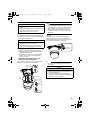
VN-V686WPU_EN.book
Page 1 Wednesday, January 16, 2008
10:39 AM
PTZ IP DOME CAMERA
VN-V686U
START-UP GUIDE
Thank you for purchasing this product.
Before beginning to operate this unit, please read
the instruction manual carefully in order to make
sure that the best possible performance is
obtained.
For Customer Use:
Enter below the Serial No. which is located on the
body.
Retain this information for future reference.
Model No.
Serial No.
VN-V686U
LST0623-001A
VN-V686WPU_EN.book
Page 2 Wednesday, January 16, 2008
10:39 AM
Getting Started
Safety Precautions
Information for Users on Disposal of Old Equipment
[European Union]
This symbol indicates that the electrical and electronic equipment should not be
disposed as general household waste at its end-of-life. Instead, the product
should be handed over to the applicable collection point for the recycling of
electrical and electronic equipment for proper treatment, recovery and recycling
in accordance with your national legislation.
By disposing of this product correctly, you will help to conserve natural resources
and will help prevent potential negative effects on the environment and human
health which could otherwise be caused by inappropriate waste handling of this
product. For more information about collection point and recycling of this product,
please contact your local municipal office, your household waste disposal service
or the shop where you purchased the product.
Attention:
This symbol is
only valid in
the European
Union.
Penalties may be applicable for incorrect disposal of this waste, in accordance
with national legislation.
(Business users)
If you wish to dispose of this product, please visit our web page
www.jvc-europe.com to obtain information about the take-back of the product.
[Other Countries outside the European Union]
If you wish to dispose of this product, please do so in accordance with
applicable national legislation or other rules in your country for the treatment of
old electrical and electronic equipment.
FOR USA AND CANADA
CAUTION
RISK OF ELECTRIC SHOCK
DO NOT OPEN
CAUTION:TO REDUCE THE RISK OF ELECTRIC
SHOCK. DO NOT REMOVE COVER (OR
BACK). NO USER-SERVICEABLE PARTS
INSIDE.REFER
SERVICING
TO
QUALIFIED SERVICE PERSONNEL.
The lightning flash wish arrowhead
symbol, within an equilateral triangle is
intended to alert the user to the presence of uninsulated "dangerous voltage" within the product's enclosure that
may be of sufficient magnitude to constitute a risk of electric shock to persons.
The exclamation point within an equilateral triangle is intended to alert the
user to the presence of important operating and maintenance (servicing)
instructions in the literature accompanying the appliance.
2
Information for USA
This device complies with part 15 of the FCC Rules.
Changes or modifications not approved by JVC could
void the user's authority to operate the equipment.
This equipment has been tested and found to comply
with the limits for a Class A digital device, pursuant
to Part 15 of the FCC Rules. These limits are
designed to provide reasonable protection against
harmful interference when the equipment is operated
in a commercial environment. This equipment
generates, uses, and can radiate radio frequency
energy and, if not installed and used in accordance
with the instruction manual, may cause harmful
interference to radio communications. Operation of
this equipment in a residential area is likely to cause
harmful interference in which case the user will be
required to correct the interference at his own
expense.
This device complies with Part 15 of the FCC Rules.
Operation is subject to the following two conditions:
(1)This device may not cause harmful interference,
and (2) this device must accept any interference
received, including interference that may cause
undesired operation.
VN-V686WPU_EN.book
Page 3 Wednesday, January 16, 2008
Due to design modifications, data given in this
instruction book are subject to possible change
without prior notice.
WARNING:
TO REDUCE THE RISK OF FIRE OR
ELECTRIC SHOCK, DO NOT
EXPOSETHIS APPLIANCE TO RAIN
OR MOISTURE.
AVERTISSEMENT:
POUR EVITER LES RISQUES
D'INCENDIE OU D'ELECTROCUTION, NE PAS EXPOSER
L'APPAREIL A L'HUMIDITE OU A LA
PLUIE.
INFORMATION (FOR CANADA)
RENSEIGNEMENT (POUR CANADA)
10:39 AM
● This installation should be made by a
qualified service person and should conform
to all local codes.
● This installation shall be in accordance with
the National Electrical Code, ANSI/NFPA 70.
● The unit is to be powered by an AC 24 V
power supply.
The AC 24 V power supply should conform to
the following:Class 2 only(For USA),Isolated
power supply only(For Europe and other).
● Any Mention in this manual of Alarm inputs/
outputs have not been evaluated by UL to be
used for Burglar Alarm Functionality.
FOR USA-California Only
This product contains a CR Coin Cell Lithium
Battery which contains Perchlorate Material special handling may apply.
See
www.dtsc.ca.gov/hazardouswaste/perchlorate
This Class A digital apparatus complies with
Canadian ICES-003.
Cet appareil num rique de la Class A est
WARNING (FOR EUROPE):
This is a Class A product. In a domestic environment
this product may cause radio interference in which
case the user may be required to take adequate
measures.
3
VN-V686WPU_EN.book
Page 4 Wednesday, January 16, 2008
10:39 AM
Getting Started
These are general IMPORTANT SAFEGUARDS and certain items may not apply to all appliances.
IMPORTANT SAFEGUARDS
1.
2.
3.
4.
Read all of these instructions.
Save these instructions for later use.
All warnings on the product and in the operating instructions should be adhered to.
Unplug this appliance system from the wall outlet before cleaning. Do not use liquid cleaners or
aerosol cleaners. Use a damp cloth for cleaning.
5. Do not use attachments not recommended by the appliance manufacturer as they may cause hazards.
6. Do not use this appliance near water - for example, near a bathtub, washbowl, kitchen sink, or
laundry tub, in a wet basement, or near a swimming pool, etc.
7. Do not place this appliance on an unstable cart, stand, or table. The appliance may PORTABLE CART WARNING
fall, causing serious injury to a child or adult, and serious damage to the appliance. (symbol provided by RETAC)
Use only with a cart or stand recommended by the manufacturer, or sold with the
appliance. Wall or shelf mounting should follow the manufacturer’s instructions,
and should use a mounting kit approved by the manufacturer. An appliance and
cart combination should be moved with care.
Quick stops, excessive force, and uneven surfaces may cause the appliance and
cart combination to overturn.
8. Slots and openings in the cabinet and the back or bottom are provided for
S3125A
ventilation, and to insure reliable operation of the appliance and to protect it from
overheating, these openings must not be blocked or covered. The openings
should never be blocked by placing the appliance on a bed, sofa, rug, or other similar surface.
This appliance should never be placed near or over a radiator or heat register. This appliance should
not be placed in a built-in installation such as a bookcase unless proper ventilation is provided.
9. This appliance should be operated only from the type of power source indicated on the marking label.
If you are not sure of the type of power supplied to your home, consult your dealer or local power
company. For appliance designed to operate from battery power, refer to the operating instructions.
10.For added protection for this product during a lightning storm, or when it is left unattended and
unused for long periods of time, unplug it from the wall outlet and disconnect the antenna or cable
system. This will prevent damage to the product due to lightning and power-line surges.
11.Do not allow anything to rest on the power cord. Do not locate this appliance where the cord will be
abused by persons walking on it.
12.Follow all warnings and instructions marked on the appliance.
13.Do not overload wall outlets and extension cords as this can result in fire or electric shock.
14.Never push objects of any kind into this appliance through cabinet slots as they may touch
dangerous voltage points or short out parts that could result in a fire or electric shock. Never spill
liquid of any kind on the appliance.
15.Do not attempt to service this appliance yourself as opening or removing covers may expose you to
dangerous voltage or other hazards. Refer all servicing to qualified service personnel.
16.Unplug this appliance from the wall outlet and refer servicing to qualified service personnel under
the following conditions:
a.
b.
c.
d.
When the power cord or plug is damaged or frayed.
If liquid has been spilled into the appliance.
If the appliance has been exposed to rain or water.
If the appliance does not operate normally by following the operating instructions. Adjust only those controls
that are covered by the operating instructions as improper adjustment of other controls may result in damage
and will often require extensive work by a qualified technician to restore the appliance to normal operation.
e. If the appliance has been dropped or the cabinet has been damaged.
f. When the appliance exhibits a distinct change in performance - this indicates a need for service.
17.When replacement parts are required, be sure the service technician has used replacement parts
specified by the manufacturer that have the same characteristics as the original part. Unauthorized
substitutions may result in fire, electric shock, or other hazards.
18.Upon completion of any service or repairs to this appliance, ask the service technician to perform
routine safety checks to determine that the appliance is in safe operating condition.
4
VN-V686WPU_EN.book
Page 5 Wednesday, January 16, 2008
Contents
10:39 AM
Setting Using Internet Explorer
T For [Setting Using Internet Explorer],
please refer to [INSTRUCTIONS](pdf) in
the supplied CD-ROM.
Getting Started
Safety Precautions ........................................ 2
Contents........................................................ 5
Features ........................................................ 6
Safety precautions......................................... 7
Operating Environment ................................. 8
Precautions ................................................... 8
Name and Function of Parts ....................... 12
Features ...................................................... 14
Camera Mounting Procedures .................... 15
Built-in Viewer .............................................
Preparation..................................................
JPEG Viewer...............................................
MPEG4 Viewer............................................
Shortcut for Built-in Viewer..........................
32
33
36
38
40
Others
Specifications .............................................. 41
Specifications (contiuned) ........................... 42
Connection/Installation
Mounting the Camera..................................
Power Connection .......................................
LAN Cable Connection................................
Connecting the alarm signal terminal..........
Network Requirements................................
Settings and operation of the Builtin Viewer
16
20
22
22
24
Network Settings
IP Address Settings.....................................
Setting the IP address for VN-V686U......
When the IP address of VN-V686U
is known...............................................
When the IP address of VN-V686U
is unknown...........................................
26
26
31
31
5
VN-V686WPU_EN.book
Page 6 Wednesday, January 16, 2008
10:39 AM
Getting Started
Features
Privacy Mask function
This function allows you to Blankout areas that you
do not wish to display in the location to be
recorded.
Realizing a High Picture Quality
This product uses high resolution 410,000 pixels
CCD and a new digital image processing IC to
achieve high resolution and image quality.
Automatic Tracking function
This product is equipped with a function that easily
tracks moving objects when home position is
displayed.
Long Magnification Zoom Lens
The optical 36 times long magnification lens allows
you to conduct detailed monitoring. The high power
and large focal ratio F1.6 (WIDE edge) and bright
zoom lens realize 1.0 lux (AGC Super, 50 %) high
sensitivity during color mode.
Equipped with high precision high
speed rotation platform
The newly developed direct drive rotation platform
rotates at a high speed of 400⬚/s both horizontally
and vertically, thus allowing the camera to move to
the preset positions quickly. As it does not have a
slowdown mechanism, it is very durable, has a high
stopping accuracy and can rotate smoothly even at
low speed.
Image Stabilizer
This function detects camera shaking and reduces
image shaking.
Motion Detection Feature
This feature enables output of an alarm upon
detection of motion in the video image within preset
area. Pre-/Post-recorded JPEG image files can be
sent to FTP server by the alarm.
Built-in JPEG and MPEG4 Viewer
Monitoring of JPEG and MPEG4 images via a
computer is possible by downloading the built-in
viewer onto the computer.
Dual Stream Full Frame Rate
Transmission
Compatibility with analog peripheral
equipment
Dual stream (JPEG, MPEG4) data transmission is
possible in VGA size at a rate of 30 fps.
The shape of this product is the same as analog
CCTV monitoring cameras and can be used with
other peripheral equipment such as brackets.
Support for Multicast
This product supports multicast, which enables
transmission of image data to multiple computers
on the network without lowering the frame rate.
Built-in Web Server
You can configure the picture quality and
communication settings using the Internet Explorer.
HTTP-based API
This product comes with HTTP-based API. This
feature enables you to perform setting and control
via the network.
Day/Night surveillance
This product is equipped with infrared filter
mechanism for day/night surveillance. During low
illuminance such as nighttime, switching out the
infrared filter will switch the product to high
sensitivity mode (B&W).
6
Progressive Output
This function realizes high picture quality of moving
objects by fixing combing noise on the contour of
the objects.
This manual contains general usage of
VN-V686U camera.
Please refer to [INSTRUCTIONS] for
description on the detailed instructions
of VN-V686U.
For the latest information, please refer to
the AReadmeB file in the CD-ROM supplied
with this product.
● The supplied CD-ROM includes
[INSTRUCTIONS] (pdf), [API Guide] (pdf)
and [Search tool].
● To view file in pdf format, the installation of
[Adobe Reader] on the PC is required.
VN-V686WPU_EN.book
Page 7 Wednesday, January 16, 2008
● Before starting an important recording, be
sure to perform a test recording in order to
confirm that a normal recording is possible.
● We do not accept liability for the loss of a
recording in the case of it becoming
impossible to record due to a problem in
the video camera, VTR, hard disk recorder
or video tape.
● The Automatic Tracking function and the
Motion Detection function are simple
functions and cannot be used as a
substitute for a security alarm. JVC shall
not be liable for any inconveniences or
damages caused in the event of error
detection or when these functions cannot
be detected. We shall not be liable for any
inconveniences or damages caused as a
result of operational failure for alarm input/
output.
10:39 AM
Safety precautions
Mounting to a firm place
As the unit rotates at high speed, mount it on a
firm place with sufficient strength to support the
vibration and weight of the unit (approx. 5.5 kg).
If the strength is weak, the vibration will cause
fuzzy images on the monitor screen. In the worst
scenario, the camera may even fall off and hit
somebody, resulting in serious accidents.
Mounting the camera correctly with
the designated clamping brackets
Always use the designated clamping brackets.
Be sure to connect the fall prevention wire and
tighten the fixing screws or nuts securely.
Using the correct power and voltage
How to Read this Manual
䡵 Symbols used in this manual
Note
Memo
A
: States precautions to be taken
during operation.
: States restrictions on the
functions or use of this
equipment. For reference
purposes.
: Indicates the page numbers or
items to refer to.
䡵 Contents of this manual
● JVC holds the copyright to this manual. Any
part or all of this manual may not be
reproduced without prior consent from the
company.
● Windows is a registered trademark of
Microsoft Corporation in the U.S.
● Product names of other companies
described in this manual are trademarks or
registered trademarks of the respective
companies. Symbols such as 姠, 姞 and 姝
are omitted in this manual.
● Design, specifications and other contents
described in this manual are subject to
change for improvements without prior
notice.
The rated power of this product is AC 24 V, 50
Hz/60 Hz. Supplying a power beyond the rated
value may result in failures and in the worst
scenario, smoking and fire.
This unit is able to divert lightening conduction to
itself and the connecting cables to a certain
extent but this is not 100 % guaranteed. For
installation locations that are likely to suffer
lightening strikes, be sure to take appropriate
measures such as adding arrestor to the
connecting cables.
Consult your dealer as special technique is
required when installing this product. Ensure that
the fixing screws or nuts are tightened securely,
otherwise, the unit may fall off.
Inspect the unit regularly.
Screws may be loosened due to vibration or
deterioration of the mounting section. Perform
regular inspections for loosened screws and
check whether there is any danger of the unit
falling off.
Do not hang on this product, shake it, or hand
objects over it. Applying an excessive load may
cause the product to fall off and result in
accidents.
Do not modify this product. It may result in
accidents.
7
VN-V686WPU_EN.book
Page 8 Wednesday, January 16, 2008
10:39 AM
Getting Started
Operating Environment
Recommended Computer
Specifications
OS
: Windows XP (Professional or
Home Edition) (SP2)
CPU
: Pentium4 1.5 GHz or higher
Memory capacity: 1 GB and above
Free hard disk space
: 512 MB or more
Display and video card
: 1024 ⳯ 768 pixels or higher,
True Color (24 or 32 bits)
VRAM 8 MB or more (256 MB
and above recommended)
Web browser : Internet Explorer Version 6.0
LAN Environment
● 10BASE-T/100BASE-TX network
interconnected using devices such as an
IEEE802.3-compliant switching hub.
● IGMPv2-compliant network when multicast is
in use.
Memo:
● The above PC specifications are guides for
smooth use of the applications, and not a
guarantee of their operation.
● Depending on the condition of use,
applications may not run smoothly even when
the user’s computer meets the specification
requirements.
● Using a computer for which its performance
does not meet the requirements may cause
the JPEG playback frame rate to deteriorate.
In addition, it also causes delay in the
MPEG4 playback images, and may result in
interruption in playback.
● To make use of the built-in MPEG4 Viewer of
VN-V686U, install “ffdshow” that is open
source codec. You can download “ffdshow”
from the Internet.
8
Precautions
Maintenance and operating environment
䢇 This product is an indoor camera. It cannot be
used outdoors.
䢇 This product is a pendant mount camera. Be
sure to place the camera head horizontally. The
product will not work properly if it is tilted.
䢇 Do not store in the following environments.
It might result in malfunctions or failure.
● Hot or cold locations beyond the
surrounding temperature range of -10 I to
50 I.
● Locations beyond the allowable operating
humidity range of 20 %RH to 90 %RH.
(condensation is not allowed)
● Near equipment that emits strong magnetic
fields, such as transformers or motors.
● Near equipment that emits radio waves,
such as transceivers and mobile phones.
● Locations with excessive dust and sand.
● Locations that are subject to vibration such
as inside the car or ship.
● Locations prone to moisture such as window
side.
● Locations subject to steam or oil, such as
kitchens.
● Special environment, such as those with
combustible atmosphere
● Locations that emit radiation, X-rays, salt
attack or corrosive gases.
● Locations where medicine is used such as
pool.
䢇 Use of this product and cables connected to this
product at locations where strong electric waves
and magnetic waves are generated (e.g., near
radio, TV, transformer, monitor, etc.) may cause
noise interferences in the images or changes in
the color.
䢇 Inadequate heat ventilation may result in
malfunction of this product. Be sure not to block
vents around the product. This product
discharges heat from the surface of the main
unit.
䢇 Do not install it at locations directly subjected to
cold air such as near the vents of airconditioners or at locations with high
temperature. Condensation may occur inside
the dome cover.
VN-V686WPU_EN.book
Page 9 Wednesday, January 16, 2008
Disclaimer
䢇 The Automatic Tracking feature is not a
feature to prevent theft or fire. Our company
shall not be liable for any inconveniences or
failures that occur.
䢇 We shall not be responsible for any
inconveniences or disturbances caused in
the event of privacy invasion as a result of
camera footages of this product.
Others
䢇 Do not subject the lens to strong light source such
as sun rays. This may cause the equipment to
malfunction.
䢇 This camera comes with a built-in AGC circuit. The
sensitivity increases automatically at a dark place
and the screen may appear grainy. This is not a
malfunction.
䢇 While AGC is activated, if a transceiver which
causes strong electromagnetic wave is used near
the camera, the picture may suffer from beat.
Please use the camera more than three meters
away from such transceivers.
䢇 When automatic iris is selected, the Iris Control
button may not work depending on the brightness
of the screen (when the amount of light is not
sufficient). In this case, set the iris to Manual.
䢇 When automatic iris is selected and AGC is ON,
even if the iris setting can be changed with the Iris
Control button, the Sense Up function will be
enabled and the brightness of the screen may not
change. In this case, set AGC to OFF or set the iris
to Manual.
䢇 When this camera is used in the White Balance
AATW-NarrowB, AATW-WideB (automatic
adjustment) mode, the color tone may differ
slightly from the actual color due to the principle of
the automatic tracking white balance circuit. This is
not a malfunction.
䢇 If a high brightness object (such as a lamp) is shot,
the image on the screen may have white vertical
tailings. This phenomenon (smear) is
characteristic of solid-state image sensors and is
not a malfunction.
䢇 Do not touch the dome cover with your hands.
Dirty covers will cause image deterioration.
䢇 Do not subject the dome cover to strong impact. It
may result in damage and water seepage.
䢇 The dome cover may fog due to the drastic change
of temperature when humidity is high.
䢇 Do not connect an AC 24 V cable to AC 110 V/AC
230 V power supply. The camera will be damaged.
If the wrong cable is connected, the internal circuit
may be damaged. Do not use the camera. Bring it
to your nearest JVC dealer for inspection.
10:39 AM
䢇 To supply AC 24 V, use a AC 24 V supplying power
unit that is insulated from AC 110 V/AC 230 V line.
䢇 When using multicast, make use of a IGMPv2compliant network switch.
䢇 Some hubs/switches of products that are equipped
with intelligent features may include a broadcast/
multicast suppression function. Viewing of
multicast images on this product may fail if this
function is enabled.
䢇 The electronic shutter of this product is set to 1/60
by default. For regions with a commercial power
supply frequency of 50 Hz, switch to the 1/100
during use under fluorescent lights (excluding
inverter lighting equipment) to prevent flickers.
䢇 When the B&W mode is set to AAutoB, the image
turns black-and-white in a dark location. As the
sensitivity level is increased in this case, the
screen may appear grainy and more white spots
may appear. When switching between color and
black-and-white images, the brighter area on the
screen is emphasized, which may reduce the
visibility. However, this is not a malfunction.
䢇 If the power supply voltage is momentarily cut off
or reduced due to lightning or turning on of the air
conditioner’s power, the image may be disrupted
or noise interference may occur.
䢇 As the dome cover is of a semiglobular shape,
image distortion will occur at the hemispherical
edge. When the hemispherical edge of this unit is
masked and horizontal level is shot in a tilt
direction, the hemispherical edge will enter the
field angle. This may cause the upper edge of the
screen to become black and the focus unclear. In
this case, you can avoid shooting the above area
by using the tilt limit settings.
䢇 When shooting objects with a luminance
difference or near a light source, ghost may occur
on the screen. This is a feature of the dome cover
and the built-in lens, and is not a malfunction.
䢇 In particular, manual and auto pan operation near
the TELE edge (telephoto side) may cause the
screen to vibrate (unsmooth rotation). This is a
feature of the motor and is not a malfunction.
䢇 As long magnification lens is used in this product,
the focus may be unclear due to temperature
changes but this is not a malfunction.
䢇 Preset the focus under an environment with a
temperature closest to that in your actual usage. If
the temperature change is large and the focus
becomes unclear, preset the focus again before
using the product.
䢇 If you sense that the focus has become unclear
due to temperature changes, use the One Push
AF function or reset the focus manually.
9
VN-V686WPU_EN.book
Page 10
Wednesday, January 16, 2008
10:39 AM
Getting Started
Precautions (contiuned)
Transporting the unit
䢇 Remove the connecting cables when
transporting the unit.
䢇 When transporting the unit, turn off the power
of the system.
䢇 Pack the unit with cushioning material so as
to avoid shock when transporting.
䢇 Handle the unit with care and do not subject it
to vibration or shock.
Transportation
䢇 Do not throw away the original box of the unit.
Keep it and use it for transporting the unit in
future.
䢇 As the camera unit is of an easily rotatable
structure, secure the camera unit inside the
dome cover such that it does not rotate
before transporting. Otherwise, an error may
occur during camera operation.
AFace the heat release vents upward and
secure the lens section with tape.
BInsert cushioning material wrapped with air
caps (approx. 50 mm x 200 mm) at two
opposite sides of the camera.
Cushioning material
A Secure with tape
B
Copyright Protection
䢇 With the exception of the user being the
copyright holder or when permission such as for
duplication has been granted by the copyright
holder, permission is required in principle for the
duplication, modification, or transmission of
copyrighted video and audio data.
Unauthorized duplication, modification, or
transmission of copyrighted material may
constitute a copyright infringement, and the
user may be liable to compensate for any
damages. When using copyrighted video/audio
data, be sure to check the license agreement of
the copyrighted material thoroughly.
When rights or rights holders are involved with
regard to the targeted duplicating subject,
permission may be required for shooting or
using (processing) it. Be sure to check the
licensing conditions thoroughly.
Maintenance
䢇 Turn off the power before performing
maintenance.
䢇 Wipe using a soft cloth.
Wiping with thinner or benzene may melt or
tarnish its surface. For tough stains, wipe using
a cloth that is dipped into a neutral detergent
diluted with water, followed by wiping with a dry
cloth.
䢇 When the same position is monitored for 24
hours continuously over a long period, the
increased contact resistance on the horizontal
rotation section may cause noise interferences
in the images and operation from the computer
may become unstable. As such, this product is
equipped with an auto cleaning function that
performs cleaning once a week.
䡵 Consumable parts
Saving Energy
䢇 When the camera is not in use for a long
time, turn off the power of the system for
safety and energy conservation reasons.
10
The following are consumable parts. They must
be replaced once they reach their lifetime.
The lifetime is only an estimation and differs
according to the usage environment and
conditions. Replacement of consumable parts is
chargeable within the guarantee period.
● Zoom lens assembly
Zoom operation..... Approx. 2 million operations
Focus operation .... Approx. 4 million operations
● Slip ring ......... Approx. 5 million operations
● Cooling fan .............. Approx. 50,000 hours
● Heater relay............ Approx. 100,000 times
VN-V686WPU_EN.book
Page 11
Wednesday, January 16, 2008
10:39 AM
䡵 Auto Focus
This unit is equipped with One Push Auto Focus
and Easy AF Auto Focus functions. However,
depending on the object and the camera setting,
it might be out of focus. In this case, please
adjust the focus manually.
● Objects which are difficult to be focused
automatically
● When the brightness of the image plane is
extremely high (bright)
● When the brightness of the image plane is
extremely low (dim)
● When the brightness of the image plane is
constantly changing (for example, a
blinking light)
● When there is almost no contrasts.
● When there are repetitive vertical striped
patterns on the image plane
● Auto Focus is difficult to set under the
following conditions
● When sensitivity is increased with AGC
and the screen is grainy
● When there is less movement on the
screen due to the Sense Up function.
● When there is no contour element in
electronic zoom
䡵 Zoom Operation
The following phenomena are the result of the
built-in lens performance and are not
malfunctions.
● When manual operation or preset is
selected, focus moves slightly after the
zoom operation has stopped near the
TELE edge.
● Manual zoom operation is not smooth.
● When Preset is selected, the camera
becomes out of focus for an instant during
zooming.
䡵 Preset Positions
The total number of preset positions that can be
set in this unit is 100, including the home position
and 99 preset positions.
11
VN-V686WPU_EN.book
Page 12
Wednesday, January 16, 2008
10:39 AM
Getting Started
Name and Function of Parts
Ceiling mount section
䡵 Terminal
H
A
䡵 Reverse side
J
G
B
C
F
D
E
I
A Fixing holes (x3)
E Fall prevention wire fixing bracket
This hole is for mounting the ceiling clamping
bracket to the ceiling or the ceiling recessed
bracket (WB-S685: Sold separately).
This attaches to the fall prevention wire K of the
camera.
F Wire clamp fixing hole
B [AC24VHINPUT] AC24V Input terminal
This is used to bundle wires. (A Page 17)
This connects the camera to AC24V power.
G Safety wire mounting hole
C [10BASE-T/100BASE-TX] LAN cable
connection terminal
Mount wires from the ceiling slab or channel to this
hole to prevent the camera from falling.
This connects the unit to the network. (A Page 22)
H Power indicator
D Alarm input/Alarm output terminal
The indicator lights up in green when AC24V power
is turned on.
This terminal is for alarm input/alarm output.
(A Page 22)
Pin number
12
Signal Name
1
Input 1
2
Input 1 COM
3
Input 2
4
Input 2 COM
5
Output 1
6
Output 1 COM
7
Output 2
8
Output 2 COM
I [Mac address] indication
The MAC address is a unique physical address of
the product. This address cannot be altered.
J Camera connection terminal (female)
This connects to the connection terminal (male) of
the camera.
VN-V686WPU_EN.book
Page 13
Wednesday, January 16, 2008
10:39 AM
Camera
O
K
L
L
M
P
N
K Fall Prevention Wire
This is fixed to the fall prevention wire fixing bracket
E of the ceiling clamping bracket.
L Front Mask
M Lens
Lens cannot be replaced.
N Camera fixing lock knob (x2)
This mounts the camera on the ceiling and secures
it so that it does not fall.
O Cable cover
To pull the cables from the side and mount the
camera, remove the cover. (A Page 17)
P Dome Cover
The dome cover is a delicate object. Handle it with
care.
Note:
● Do not peel off the protective sheet which is
attached at shipment, until the dome cover is
mounted on the main unit. (A Page 18)
13
VN-V686WPU_EN.book
Page 14
Wednesday, January 16, 2008
10:39 AM
Getting Started
Features
Surveillance via Dual Stream
Surveillance Using the Built-in Viewer
VN-V686U comes with a built-in ActiveX JPEG
Viewer and MPEG4 Viewer.
JPEG images and MPEG4 images of VN-V686U
can be monitored using the computer by installing
this built-in viewer on the computer. JPEG images
that are currently displayed can also be captured in
the computer’s hard disk.
ABuilt-in ViewerB (A Page 32)
Simultaneous distribution of JPEG and MPEG4
images enables real-time surveillance using
MPEG4 (30 fps) and recording of JPEG images at
the same time. You can also lengthen the recording
time by lowering the frame rate, resolution, and
picture quality settings for JPEG images.
Real-time Surveillance
Using MPEG4
VN-V686U
VN-V686U
Computer
Network
Storage Device
Recording JPEG Images
Network
Computer
VN-V686U accepts requests from 20 clients at
maximum.
Monitoring via Multicast
Multicast enables monitoring of JPEG and MPEG4
images on multiple computers.
Saving JPEG images to the FTP server
at regular intervals
JPEG images may be uploaded to the FTP server
at regular intervals.
VN-V686U
VN-V686U
Computer
IGMPCompliant
Network
Computer
Network
Uploads the latest JPEG
images to the FTP server at
regular intervals
Computer
14
Computer
VN-V686WPU_EN.book
Page 15
Wednesday, January 16, 2008
10:39 AM
Camera Mounting
Procedures
Alarm
VN-V686U comes with a motion detection feature
and dual alarm input.
By motion detection or alarm input, actions such as
mail delivery, message transmission via TCP/UDP,
alarm output, turning to preset position, changing
B&W mode can be triggered. These actions can
also be triggered by combination of two alarm
inputs.
Installing an FTP server enables uploading of
JPEG images before and after the alarm input time
(pre-/post-recording) to the server.
Alarm Device
VN-V686U
Mount the camera using the following procedures.
Step 1 Connection/Installation
(A Page 16)
\
Preparation (A Page 16)
Mounting the ceiling clamping bracket (A
Page 18)
Mounting the camera (A Page 18)
G
\
Step 2 Network settings (A Page 26)
Configure the network settings of the computer
and this camera.
Network
Sending JPEG images
before and after alarm
input to FTP
Computer
Restrictions on Clients
VN-V686U enables users to authorize or reject
the acquisition of images by specific IP address.
Control via customized application
software
The following uses are also possible by developing
a customized application software that supports the
API of VN-V686U.
For details, please refer to [API GUIDE] in the
supplied CD-ROM.
● Monitors via the computer while at the same
time records images to the HDD of the
computer.
● Performs recording by changing the frame
size/frame rate during alarm occurrence.
● Records the type and time of alarm
occurrence on the computer.
T In a system where multiple units of VNV686U are used, turn on the power of only
one unit to configure the IP address settings
using the Internet Explorer. Upon doing so,
turn on the power of the second unit and
configure accordingly. Configure the settings
for the other cameras using the same
procedure.
G
Step 3 Configuring settings using the
Internet Explorer
Configure the picture quality and alarm settings
using the Internet Explorer.
T For detailed usage of VN-V686U, please
refer to [INSTRUCTIONS](pdf) in the
supplied CD-ROM.
G
Step 4 Operating the built-in viewer
(A Page 32)
The built-in viewers enable you to monitor JPEG
and MPEG4 images and save JPEG images.
T For detailed usage of VN-V686U, please
refer to [INSTRUCTIONS](pdf) in the
supplied CD-ROM.
15
VN-V686WPU_EN.book
Page 16
Wednesday, January 16, 2008
10:39 AM
Connection/Installation
4 Mount the fall prevention wire that
Mounting the Camera
connects the ceiling clamping bracket
to the ceiling
6 mm
(15/64 inch)
Preparation
䡵 Fall Prevention Wire
Be sure to put on protective glasses to protect
your eyes from falling objects when mounting the
camera.
6 mm and below
R6 mm and below
1 Make holes on the ceiling
● Use the provided template to make a hole
(R80 mm) for the connection cables to thread
behind the ceiling.
● If necessary, also open a screw hole to mount
the ceiling clamping bracket to the ceiling. In
this case, align the AD FRONT markB of the
template in the direction where the camera
faces front and open the screw hole.
2 Pull the cables from the hole in the
ceiling
Pull out the fall prevention wire, power cable,
coaxial cable, control signal cable, alarm signal
cable and provided alarm cable that were mounted
to the ceiling slab from the ceiling.
1
80
Fall Prevention
Wire
LAN Cable
Power cable
Alarm signal cable
2
Note:
● Mount the fall prevention wire on a firm place
with sufficient strength.
3 Remove the terminal cover
Loosen two screws on the ceiling clamping bracket
and remove the terminal cover.
R4 to 5.5 mm
Caution
● Take note of the length, strength, pull and
material (insulation) of the fall prevention wire
and use one with a wire strength of more than
20kg.
● The inner diameter of the ring section of the
fall prevention wire mounted on the camera
should be R4 mm to R5.5 mm and the outer
diameter be R9 mm and below.
● The thickness of the screw head and the fall
prevention wire (including the washer) should
be 6 mm and below. If it is more than 6 mm,
the screw will touch the ceiling and the
camera cannot be installed horizontally.
● Use M4 fixing screws.
Memo:
● The wire should be insulated from the ceiling
structure. If the ceiling structure is metal and
insulation is not provided between the
camera and the ceiling structure, image noise
may occur.
5 Connect the cable (A Page 20 to 23)
Connect cables to the terminal of the ceiling
clamping bracket.
The connection cables consist of the alarm signal
cable, LAN cable and AC24V power cable.
A Power cable (A Page 20)
Terminal cover
This connects to AC24V power.
B Alarm input/output signal terminal
(A Page 22)
This connects to devices with alarm input/output
terminals.
C LAN cable (A Page 22)
This connects the unit to the network.
16
VN-V686WPU_EN.book
Page 17
Wednesday, January 16, 2008
10:39 AM
7 Mount the terminal cover
A LAN Cable
B Power cable
Return the terminal cover that was removed in step
3 to its original position. The direction to pull out
the cables changes according to the mounting
method of the camera.
䡵 Pulling out the cables from the side
C Alarm signal cable
Note:
● Do not connect an AC 24 V cable to AC 100
V power supply. The camera will be
damaged. If the wrong cable is connected,
the internal circuit may be damaged. Do not
use the camera. Bring it to your nearest JVC
service center for inspection.
● For safety reasons, turn on the power only
after all the connection is complete.
● To supply AC 24 V, use a AC 24 V supplying
power unit that is insulated from AC 100 V
line.
Terminal cover
䡵 Pulling out the cables from the top
Fall Prevention Wire
(To go under the terminal cover)
6 Handling cables
Thread the provided wire clamp through the wire
clamp fixing hole of the ceiling clamping bracket to
tie all the wires.
Terminal
cover
Wire clamp fixing
hole
Tie here
Wire clamp
Note:
● Be sure to mount the terminal cover to
prevent foreign objects or dust from entering.
● When pulling out the cables from the top,
make the fall prevention wire go under the
terminal cover and pull it out together with the
other cables.
● When pulling out the cables from the side,
remove the cable cover of the camera.
Cable cover
Note:
● To prevent the cables from tangling and
coming off, be sure to thread a wire clamp
through the wire clamp fixing hole to tie the
cables.
17
VN-V686WPU_EN.book
Page 18
Wednesday, January 16, 2008
10:39 AM
Connection/Installation
Mounting the Camera
(contiuned)
Mounting the camera to the ceiling
1 Remove the tape on the lens section
2 Remove the lens cap
Mounting the ceiling clamping bracket
to the ceiling
1
1 Secure the ceiling clamping bracket
Tape
on the ceiling
● Install such that the ADFRONT markB of the
ceiling clamping bracket faces the front.
● Ensure that the connection cables are not
caught in between and secure the ceiling
clamping bracket on the ceiling with 3 screws.
Front of the
camera
Lens cap
2
Camera
3 Mount the dome cover to the camera
A Check that the dome cover and lens are
free from dirt.
DFRONT mark
B Turn the dome cover in a clockwise direction
to mount.
Screws
5 mm (3/16 inch)
and below
Note:
● Use M4 fixing screws and bolts.
● Use R4.1 wood screws.
● The length of the screws should be 25 mm
(1inch) and above.
● Place the product horizontally and install. The
camera will not operate properly if it is slanted.
● The screw head should be 5 mm and below. If
the ceiling structure is metal, image noise may
occur.
● Do not use the type of screw that the screw
head will go under the hole when tightening.
(flathead screw etc)Resin part for insulation
will be damaged causing loss of insulation.
Memo:
● Always use 3 screws and mount securely.
● Tighten the screws again during maintenance
just to be safe.
● The plastic parts on the ceiling fixing holes of
the ceiling clamping bracket act as an insulation
between the ceiling clamping bracket and the
ceiling structure. If the ceiling structure is metal
and insulation is not provided between the
camera and the ceiling structure, image noise
may occur. Be sure to provide insulation.
18
Note:
● Be sure to turn the dome cover until it stops
and tighten securely. Make sure that the
dome cover is not slanted.
● Do not over-rotate the dome cover. This may
damage the dome cover.
Memo:
● If it is difficult to screw on the dome cover,
turn it in an anticlockwise direction until you
hear a click sound, then turn it in a clockwise
direction. It will screw on smoothly.
4 Remove the dome cover protective
sheet
4
Dome cover
protective
sheet
Dome Cover
3
VN-V686WPU_EN.book
Page 19
Wednesday, January 16, 2008
Caution
● The dome cover is an optical parts. Handle
with care.
● When mounting the dome cover, make sure
that there is no dirt inside the cover.
● Tighten the dome cover securely.
5 Mount the fall prevention wire
Mount the fall prevention wire, which is attached to
the camera, to the fall prevention wire fixing bracket
of the ceiling clamping bracket.
Caution
10:39 AM
Note:
● Before mounting the camera, check that the
camera fixing lock knobs are not locked (i.e.,
lock knobs are on top). The camera cannot
be mounted if the lock knobs are locked.
● When pulling out the cables from the side,
remove the cable cover of the camera. (A
Page 16)
8 Lock
When the camera is mounted on the ceiling
clamping bracket, lower the camera fixing lock
knobs (x2) in the direction of the arrow and secure
the camera such that it does not fall off.
● Be sure to connect the fall prevention wire.
Otherwise, the camera may fall.
● To prevent danger, do not leave the fall
prevention wire dangling by the camera.
Camera fixing
lock knob (x2)
6 Mount the camera
● Align the ADB mark (blue)/(red) inside the
camera with the ADB mark (blue)/(red) on the
ceiling clamping bracket.
● Insert the camera into the ceiling clamping
bracket until you hear a click sound and
mount it securely.
7 Check that the camera fixing lock
knobs (x2) are sticking out.
If the camera is mounted on securely, the camera
fixing lock knobs (x2) will stick out a little.
Fall prevention
wire fixing bracket
Memo:
● To remove the camera, follow the reverse
procedures.
5
Caution
D mark
(blue)
6
D mark (red)
● Be sure to check that the camera fixing lock
knobs (x2) are locked securely. Otherwise,
the camera may fall.
● After mounting, check that the camera is
mounted securely. Improper mounting may
cause the camera to fall off.
Fall Prevention Wire
7
During
mounting
After
mounting
19
VN-V686WPU_EN.book
Page 20
Wednesday, January 16, 2008
10:39 AM
Connection/Installation
Power Connection
Warning
Note:
● Be sure to use an AC 24 V supply that is
isolated from the primary power supply
circuit. Using a variable voltage power supply
will cause the camera and system to
malfunction or breakdown.
● The unit is to be powered by an AC 24 V
power supply. The AC 24 V power supply
should conform to the following: Class 2 only
(For USA), Isolated power supply only (For
Europe and others).
Connecting the power cable
This connects the camera to AC24V power.
Power cable
To Power Supply
When using 2-core VVF (Vinyl-insulated vinylsheath cable), the connection distance is as
follows: (Reference value)
Maximum
connection
distance
40 m
100 m
170 m
210 m
Conductor
Diameter
(AWG No.)
R1.0mm
(18) and
above
R1.6mm
(14) and
above
R2.0mm
(12) and
above
R2.6mm
(9) and
above
20
● The rated power of this product is AC 24 V,
50 Hz/60 Hz. Make sure to use it with the
correct voltage.
● Supplying a power beyond the rated value
may result in failures, smoke or fire. When
the camera breaks down, turn off the
power and contact our service center
immediately.
● When a power beyond the rated value is
supplied, the internal components may be
damaged even if no abnormality is found
on the appearance and operation of the
camera. Please contact your nearest JVC
dealer immediately for servicing (charged
separately).
Memo:
● After DHCP timeout, all IP addresses of VNV686U are set to 192.168.0.2 by default.
When the power of multiple cameras within
the same LAN environment are turned on at
the same time, the IP address of the cameras
overlap, thus preventing proper access. As
such, make sure to turn on the power of the
cameras one by one.
● In a system where multiple units of VNV686U are used, turn on the power of only
one unit to configure the IP address settings
using the Internet Explorer. Upon doing so,
turn on the power of the second unit and
configure accordingly. Configure the camera
settings using the same procedure.
● When overlapping of the IP address occurs,
check to ensure that there is only one VNV686U unit within the same LAN
environment, and wait for a while (at least 10
minutes) or power off and on all network
devices under the same LAN environment.
Otherwise, access to VN-V686U may fail.
VN-V686WPU_EN.book
Page 21
Wednesday, January 16, 2008
10:39 AM
Note:
● If thin cables are used, the resistance of the
cables will be high and a significant voltage
drop will occur when the camera is at its
maximum power consumption (when pan, tilt
and zoom operates at the same time). Either
use a thick cable with low resistance or place
the power supply near to the camera and
shorten the length of the cable to restrict the
voltage drop at the rated current of camera to
below 10 %. If voltage drops during
operation, the camera may experience
unstable performance and be unable to call
up the preset position correctly.
● Do not connect an AC 24 V cable to AC 110
V/AC 230 V power supply. The camera will be
damaged.
● If power supply is incorrect, the internal
circuit may be damaged. Do not use the
camera. Bring it to your nearest JVC dealer
for inspection.
● Turn on the power only after the connection
for all the devices is complete.
● After the power is turned on and activation is
completed, this product will move to the
home position.
21
VN-V686WPU_EN.book
Page 22
Wednesday, January 16, 2008
10:39 AM
Connection/Installation
LAN Cable Connection
Connect the camera to a hub or computer using a
LAN cable.
Cable to use
● Shield (STP) cable
● Make use of a Category 5 (or higher) cable
when 100BASE-TX is used.
䢇 When connecting to a hub
Make use of a straight cable.
䢇 When connecting to a computer
Make use of a cross cable.
Connecting the alarm signal
terminal
Connect the alarm signal cable to external devices,
such as a sensor or buzzer.
Cable to use
● Length of 50 m or shorter
● UL1007, UL1015 or equivalent products
● AWG#22 to AWG#18 or equivalent
products
A Loosen screws on both sides of the terminal
block with a flathead screwdriver and remove
the terminal block as shown in the diagram
below.
Memo:
● Inserting the tip of the screwdriver into the slit
of the terminal block will remove the terminal
block easily.
B Peel off about 4 mm of the alarm signal cable
covering and insert into the terminal.
C Turn the screws at the side and secure the
alarm signal cable.
D When the alarm signal cable is secured,
[10BASE-T/100BASE-TX]
LAN cable connection
terminal
return the terminal block that was removed in
A to its original position.
Alarm signal terminal
C
Note:
● However, cross cables cannot be used with
some computer models. When connecting
VN-V686U directly to a computer, check the
computer’s LAN specifications in advance.
D
A
m
4
m
B
A
Note:
● Noises from an external source may cause
the camera to malfunction even when the
cable used is within 50 m. In this case, move
the cable away from the noise source.
22
VN-V686WPU_EN.book
Page 23
Wednesday, January 16, 2008
10:39 AM
Alarm input signal
Connects to sensors such as infrared sensors,
door sensors, metal sensors and manual switches.
● To prevent noise from entering the internal
circuit, supply non-voltage contact signal to
the alarm input signal.
● Do not supply voltage.
● When the contact is short (MAKE) or open
(BREAK) on the menu, you can set it to
Alarm.
● Supply such that the alarm signal continues
for at least more than 500 ms. The alarm
signal may not be recognized if it is less than
500 ms.
IN
COM
Alarm output signal
Connect to alarm devices such as alarm, indicator,
light or buzzer.
● Alarm output signal is an open collector output
insulated with photo coupler.
● During an alarm, it is ON.
● As this terminal is polarized, be sure to
connect it such that the voltage of the + output
is higher than that of the - output.
● It will be damaged if reverse voltage is
supplied.
OUTPUT
22
COM
Rating:
Max. applied voltage : DC 20 V
Max. driving current : 25 mA
23
VN-V686WPU_EN.book
Page 24
Wednesday, January 16, 2008
10:39 AM
Connection/Installation
Network Requirements
● Ensure that there is sufficient network
bandwidth for the data volume to be sent out
by VN-V686U. Do not send multicast stream
that exceeds the bandwidth. If the entire
bandwidth is used by the multicast stream,
control of this camera via the network may fail.
● Data volume to be sent by VN-V686U varies
with the settings and number of distributions.
● The maximum bit rate for transmission is about
20 Mbps.
Estimation of Total Bit Rate
The total JPEG bit rate from VN-V686U is
determined by the VN-V686U settings, number of
clients, and the client’s requested number of frames.
The total MPEG4 bit rate from VN-V686U is
determined by the number of distributions. Develop
a design upon taking the above into consideration.
Bit Rate of JPEG Stream
The JPEG file size per frame varies with the
encoding settings as well as input video signals. The
following table may be used as a reference. When
VFS is selected, the quantization table during JPEG
encoding will be maintained, and the file size will
increase/decrease according to the input signals.
When AFS is selected, encoding will be performed
such that the target file size is the average size of
multiple JPEG images.
Picture Quality
Control Method
VGA File
Size
QVGA File
Size
VFS
(Variable
File Size)
1 (High)
80 KB
27 KB
2
60 KB
20 KB
3
40 KB
13 KB
4 (Medium)
30 KB
10 KB
5
25 KB
8 KB
6
20 KB
7 KB
7 (Low)
15 KB
5 KB
AFS
(Average File Size)
24
Selectable
between
10 KB to
100 KB
Selectable
between
3 KB to
33 KB
The maximum number of distributions varies with the
bit rate settings as well as the client’s requested
frame rate. Up to 20 streams can be distributed
(including multicast). The total frame rate refers to
the sum of these frame rates.
For example, when 10 fps is requested by two
clients, and in addition, multicast is transmitted at a
rate of 10 fps, the total frame rate will be:
10+10+10=30 fps
If the JPEG file size per frame is 30 KB, then the
total bit rate will be:
30 KB × 30 fps 900 KB/s Approx. 7.2 Mbps
Bit Rate of MPEG4 Stream
You can select either the Variable Bit Rate (VBR) or
Constant Bit Rate (CBR) system for MPEG4 stream.
When the VBR system is selected, the bit rate varies
according to the condition of the input video signals.
The VBR system delivers a stable picture quality, but
forecast of the bit rate is difficult.
When the CBR system is selected, encoding is
performed at a fixed bit rate regardless of the
condition of the input video signals. The picture
quality varies under the CBR system, but the bit rate
can be easily forecast.
You can specify an estimated bit rate for both VBR
and CBR. (64 kbps to 8000 kbps)
Restrictions on the Number of
Distributions for VN-V686U
The maximum number of distributions for VN-V686U
is determined by the settings as well as requirements
from the client.
When only JPEG images are distributed, the
maximum number of distributions is determined based
on the highest bit rate within the stream. When a
distribution request that exceeds the maximum
number of distributions is received, this request is
denied. For example, if Client A requests for and
receives data at 1 Mbps, while Client B requests for
and receives data at 5 Mbps, the maximum number of
distributions is 4 streams according to the table below.
Maximum number of distributions when only
JPEG data is distributed
Distribution
at maximum
bit rate
Maximum
number of
distributions
Total maximum
bit rate
1 Mbps and
below
20
20 Mbps
5 Mbps and
below
4
20 Mbps
10 Mbps and
below
2
20 Mbps
Larger than 10
Mbps
1
Maximum
configurable
value (24 Mbps)
VN-V686WPU_EN.book
Page 25
Wednesday, January 16, 2008
When only MPEG4 images are distributed, the
maximum number of distributions is determined by
the preset bit rate. When a distribution request that
exceeds the maximum number of distributions is
received, this request is denied.
When distributing only MPEG4 data
Preset bit
rate
Maximum
number of
distributions
Total maximum
bit rate
0.6 Mbps and
below
20
12 Mbps
3 Mbps and
below
4
12 Mbps
6 Mbps and
below
2
12 Mbps
Larger than 6
Mbps
1
Maximum
configurable
value (8 Mbps)
When both JPEG and MPEG4 images are
distributed simultaneously, distribution up to two
clients for JPEG and MPEG4 respectively is
possible. However, distribution requests that
exceed a total bit rate of 20 Mbps will be denied.
Total bit rate
20 Mbps and
below
Maximum
number of
distributions
for JPEG
Maximum
number of
distributions
for MPEG4
2
2
Insufficient network bandwidth
When there is insufficient bandwidth, the number of
JPEG frames (frame rate) that the client can
acquire will decrease. Delay will also occur in the
distribution of images. In the case of MPEG4, noise
interference may occur and playback may fail.
Network Delay
When the client acquires JPEG via TCP, VNV686U will send out data while checking the ACK
from the client at the same time. For networks with
considerable delay, data cannot be sent out until
ACK is received, and therefore the frame rate will
drop. In the case of MPEG4, noise interference
may occur and playback may fail.
Decrease in the frame rate due to network delays
can be eliminated by receiving data via multicast.
10:39 AM
Network Jitter
When there is considerable network jitter, delay
time may be prolonged and the image frame rate
may drop. In the case of MPEG4, noise
interference may occur and playback may fail.
Packet Loss
When acquiring images from VN-V686U via TCP,
packet loss may be recovered by TCP
transmission. When there is considerable delay in
the network, however, missing data may occur and
the image frame rate may drop. In the case of
MPEG4, noise interference may occur and
playback may fail.
When packet loss occurs during multicast sending
from VN-V686U, the image frame rate may drop. In
the case of MPEG4, noise interference may occur
and playback may fail.
List of Protocols and Port Numbers
Used by VN-V686U
VN-V686U uses the protocols and port numbers
listed below. Ensure that these ports are allowed
through the firewall when a firewall is to be
installed.
Protocol/Port No.
Purpose of Use
Source
TCP/80
JPEG/MPEG4 server,
Web Settings page, API
TCP/10020
TCP/10021
TCP/10023
(Reserved for adjustment)
TCP/32040
Alarm server
Destination
TCP/20, 21
FTP
TCP/25
Mail delivery
TCP/110
POP (Mail Delivery)
TCP/User Setting
No.
Sending alarm
UDP/123
SNTP
UDP/User Setting
No.
Sending alarm
25
VN-V686WPU_EN.book
Page 26
Wednesday, January 16, 2008
10:39 AM
Network Settings
IP Address Settings
䡵 (B) Assigning a static IP address
䢇 System configuration required for setting
IP address
Setting the IP address for VN-V686U
There are two methods to set the IP address for
VN-V686U as follows.
(A) Assigning an IP address to VN-V686U
from the DHCP server
(B) Assigning a static IP address to VNV686U
䡵 (A) Assigning an IP address from the
DHCP server
● VN-V686U is set to ADHCP EnableB (the
DHCP client function is ON) by default. To
assign an IP address from the DHCP server,
connect the DHCP server to the LAN, set the
[IP setting] of VN-V686U to ADHCPB, and
click the [OK] button. (A Page 30)
● For details on IP addresses assigned to VNV686U, consult your network administrator.
You can look up the IP address of VN-V686U
using the search tool in the supplied CDROM.
For details, please refer to AReadmeB file in
the CD-ROM.
Note:
● Set the DHCP server such that the same IP
address is always assigned to the MAC
address of VN-V686U by the DHCP server.
Connection may fail if the above setting is not
performed.
26
VN-V686U at factory default is set to ADHCP
EnableB (DHCP client function is On). When it is
connected to a LAN without DHCP servers, it will
activate under the following IP address after
timeout.
IP address
: 192.168.0.2
Subnet mask
: 255.255.255.0
Default gateway : None
Memo:
● To set a static IP address for VN-V686U,
connect VN-V686U, the switching hub and
the computer for setting using a straight LAN
cable of Category 5 and above.
䢇 Set up the computer for setting the IP
address.
● Minimum computer specifications for
setting
OS
: Windows XP (Professional or
Home Edition) (SP2)
Web browser
: Internet Explorer Version 6.0
Note:
● When setting the IP address for VN-V686U,
do so by using a network that is made up only
of VN-V686U, the computer for setting and
the switching hub.
● Using a hub connected to other network
devices or networks via a LAN cable for
setting can cause problems.
VN-V686WPU_EN.book
Page 27
Wednesday, January 16, 2008
10:39 AM
䢇 IP address setting at the computer
Set the computer to an IP address that enables communication with VN-V686U.
1 Click [Start]
● Select in the sequence of [Control Panel]-[Network Connection]-[Local Area].
2 The computer on which Internet Explorer is launched automatically selects the
connected network
● Right-click and select [Properties].
● Check to ensure that the [Client for Microsoft Networks] and [Internet Protocol(TCP/IP)] check
boxes are selected.
3 Select [Internet Protocol(TCP/IP)] and click [Properties]
4 Set the IP address
A Select [Use the following IP address].
B Specify the [IP address]. (For example, use
192.168.0.100 when VN-V686U is in its default
settings and there is no DHCP server.)
Memo:
Make sure that you take note of the original IP
address before altering.
Note:
Ensure that a duplicate IP address is not
specified within the same network
environment.
C Set [Subnet mask] to a value that is
appropriate for the setting operation. Consult
the network administrator if you have any
queries.
(Use 255.255.255.0 when VN-V686U is in its
default settings and there is no DHCP server.)
D When a [Default gateway] is present, make
use of the corresponding IP address (e.g.,
192.168.0.254).
E Click [OK].
5 Click [OK] on the [Local Area Connection Propertise] screen
27
VN-V686WPU_EN.book
Page 28
Wednesday, January 16, 2008
10:39 AM
Network Settings
IP Address Settings
(contiuned)
䢇 Changing the IP address using the
Internet Explorer
1 Launch the Internet Explorer on the computer
2 When proxy settings are enabled in the Internet Explorer, follow the steps below to
disable the proxy of the Internet Explorer
● Select in the order of [Tool]-[Internet Options]-[Connections]-[LAN Setting], followed by
deselecting the check for [Use a proxy server for your LAN] under [Proxy Server] of the [Local
Area Network (LAN) Settings] window.
Deselect the check
3 If the active script of the Internet Explorer is disabled, follow the steps below to enable it
● Select [Trusted sites] under [Tool]-[Internet Options]-[Security]. Upon doing so, the [Sites…]
button directly below becomes active. Click this button and deselect the check [in the displayed
window], and add the following web site to the zone.
http://192.168.0.2
● Next, select [Trusted sites] under [Tool]-[Internet Options]-[Security], and press the [Custom
Level] button. Select [Enable] under [Scripting]-[Active script] of the [Security Settings] window
that has been opened.
Select [Enable]
28
VN-V686WPU_EN.book
Page 29
Wednesday, January 16, 2008
10:39 AM
4 Launch the Internet Explorer
A Enter the following IP address into the address field.
http://192.168.0.2
B Click [Go].
Memo:
● If the proxy server settings for access to the Internet via the Internet Explorer is enabled, you may
not be able to specify the IP address directly. In this case, change the proxy settings of the Internet
Explorer.
● After the [Security Settings] screen appears, press the [OK] button to proceed.
5 Enter the user name and password (login as administrator)
A Enter the user name.
This is set to AadminB by default.
B Enter the password.
This is set to Avn-v686B by default.
C Click [OK].
Memo:
● After the [Security Settings] screen appears, press the [Yes] button to proceed.
29
VN-V686WPU_EN.book
Page 30
Wednesday, January 16, 2008
10:39 AM
Network Settings
IP Address Settings
(contiuned)
䢇 Changing the IP address using the Internet Explorer (contiuned)
6 The top page of VN-V686U appears
Click on [Network], followed by [Basic] on
the next submenu.
7 The [Basic] page with the IP address settings appears
A Set the [IP Setting] item to [DHCP Disable].
B Enter the values you wish to specify in the
[IP Address], [Subnet Mask] and [Default
Gateway] fields.
C Click [OK].
A confirmation screen appears. Press the [OK] button. VN-V686U restarts using the new IP address. It takes
about one minute for the camera to reboot.
Memo:
● Access from this computer may fail when the IP address of VN-V686U is changed. To enable access
to VN-V686U from the same computer, alter the IP address at the computer accordingly.
When the display or configuration of the opened screen appears strange, check the computer
settings using the following procedures.
A Click [Start]-[Control Panel]-[Display] and open the [Display Properties] window
B Click the [Settings] tab in the [Display Properties] window and click the [Advanced] button
C Check that [DPI setting] in the [General] tab has become [Normal size(96DPI)]
D Otherwise, change the setting to [Normal size(96DPI)] and reboot Windows
30
VN-V686WPU_EN.book
Page 31
Wednesday, January 16, 2008
10:39 AM
When the IP address of VN-V686U is known
When the IP address of VN-V686U is known, it can
be changed by accessing the built-in web page of
VN-V686U via the Internet Explorer on the
computer.
When the IP address of VN-V686U is
unknown
IP address settings cannot be changed by
accessing via a computer when the IP address of
VN-V686U is unknown.
Use [Search tool] in the provided CD-ROM to find
the IP address. You can use this tool to search for
information on VN-V686U within the LAN.
Memo:
● For details on [Search tool], please refer to
the AReadmeB file in the CD-ROM supplied
with this product.
31
VN-V686WPU_EN.book
Page 32
Wednesday, January 16, 2008
10:39 AM
Settings and operation of the Built-in Viewer
Built-in Viewer
This product comes with a JPEG Viewer and an
MPEG4 Viewer. Each of these viewers functions
separately.
䡵 Using the JPEG Viewer enables display of
a series of still images as well as saving of
still images.
䡵 Using the MPEG4 Viewer enables display
of MPEG4-encoded motion images.
⽧AInternet Explorer SetupB (A Page 33)
⽧AInstalling the built-in viewerB
(A Page 35)
⽧AScreen Configuration of JPEG ViewerB
(A Page 36)
⽧AExiting the JPEG ViewerB (A Page 37)
⽧AScreen Configuration of MPEG4 ViewerB
(A Page 38)
⽧AExiting the MPEG4 ViewerB (A Page 39)
⽧AShortcut for Built-in ViewerB
(A Page 40)
T For setting built-in viewer, please refer to
[INSTRUCTIONS](pdf) in the supplied CDROM.
When the display or configuration of the
opened screen appears strange, check the
computer settings using the following
procedures.
A Click [Start]-[Control Panel]-[Display] and
open the [Display Properties] window
B Click the [Settings] tab in the [Display
Properties] window and click the [Advanced]
button
C Check that [DPI setting] in the [General] tab
has become [Normal size(96DPI)]
D Otherwise, change the setting to [Normal
size(96DPI)] and reboot Windows
32
VN-V686WPU_EN.book
Page 33
Wednesday, January 16, 2008
10:39 AM
Preparation
Internet Explorer Setup
1 Launch the Internet Explorer on the
computer
2 When proxy settings are enabled in the Internet Explorer, follow the steps below to
disable the proxy of the Internet Explorer
● Select in the order of [Tool]-[Internet Options]-[Connections]-[LAN Setting], followed by
deselecting the check for AUse a proxy server for your LANB in [Proxy Server] of the [Local Area
Network (LAN) Settings] window.
Deselect the check
33
VN-V686WPU_EN.book
Page 34
Wednesday, January 16, 2008
10:39 AM
Settings and operation of the Built-in Viewer
Preparation (contiuned)
3 If ActiveX controls and plug-ins of the Internet Explorer is disabled, follow the steps
below to enable it
● Click [Trusted sites] under [Tool]-[Internet Options]-[Security]. Upon doing so, the [Sites…]
button directly below becomes active. Click this button and deselect the check [in the displayed
window]. Next, add the IP address of VN-V686U. If the setting is factory default, add the following
web site to the zone.
http://192.168.0.2
● Click [Trusted sites] under [Tool]-[Internet Options]-[Security]. Select the [Custom Level] button
and open the [Security Settings] window. Set all items under [ActiveX controls and plug-ins] in
the opened window to [Enable]. Enable also [Use the following IP address] under
[Miscellaneous].
4 If the pop-up block function of the Internet Explorer is enabled, follow the steps
below to disable it
T The built-in viewer cannot be used when the pop-up block function is AenabledB.
● Selecting [Tool]-[Pop-up Blocker]-[Turn Off Pop-up Blocker] permits all sites.
● To permit only specific sites for VN-V686U, select [Tool]-[Pop-up Blocker][Turn On Pop-up Blocker]. Select the selectable [Tool]-[Pop-up Blocker]-[Pop-up Blocker
Settings] and open the [Pop-up Blocker Settings] window. In the opened window, add the
address of VN-V686U as a permitted web site address.
5 When plug-in tools such as the Yahoo or Google toolbar are included in the Internet
Explorer, disable the pop-up block function of these plug-in tools as well
Memo:
● To use the built-in MPEG4 Viewer of VN-V686U, install “ffdshow” that is open source codec. You can
download “ffdshow” from the Internet.
34
VN-V686WPU_EN.book
Page 35
Wednesday, January 16, 2008
10:39 AM
Installing the built-in viewer
1 Enter the URL of the built-in viewer in the address field of Internet Explorer
For example, if the IP address of VN-V686U is 192.168.0.2, enter as follows:
䡵JPEG Viewer
http://192.168.0.2/cgi-bin/v686viewing.cgi?v686monitor_j.html
䡵MPEG4 Viewer
http://192.168.0.2/cgi-bin/v686viewing.cgi?v686monitor_m.html
Enter the URL in the built-in viewer of this camera.
(Refer to the above for the default URL setting.)
Click [Go]
http://192.168.0.2/cgi-bin/v686viewing.cgi?v686monitor_j.html
2 Enter the user name and password
?
v
A Enter the user name.
This is set to AadminB by default.
B Enter the password.
This is set to Avn-v686B by default.
C Click [OK].
3 The viewer is installed and launched
35
VN-V686WPU_EN.book
Page 36
Wednesday, January 16, 2008
10:39 AM
Settings and operation of the Built-in Viewer
JPEG Viewer
Screen Configuration of JPEG Viewer
● When the JPEG Viewer is first installed, it is set to play back at 15 fps by default.
A
B
C
D
E
A DisplaySize
Switches the display size. (VGA or QVGA)
Note:
● When the VGA JPEG is reduced to QVGA and when QVGA JPEG is
enlarged to VGA, the load on the computer will increase.
B Capture
Captures the currently displayed image on the computer.
Images captured will be stored as a JPEG file in the folder created under [My
Document] of the computer. The default folder name is AVN-V686B. The file
name is made up of the year, month, day, hour, minute, second, and
millisecond.
The time denoted by the file name is based on the time at the computer and
not the internal clock of VN-V686U.
Motion images cannot be captured.
C Pause
Pauses/Resumes playback of images.
36
VN-V686WPU_EN.book
D PTZ
Page 37
Wednesday, January 16, 2008
10:39 AM
Open the [PTZ Controller] screen.
Manual operations are available. Configure settings of preset position
registration and Auto Pan/Auto Trace in the [PTZ Controller] screen.
Note:
● When the PTZ Controller screen is first opened in the computer,
ActiveX will be installed.
T For details of [PTZ controller Operation], please refer to
[INSTRUCTIONS](pdf) in the supplied CD-ROM.
E Setup
Displays the built-in viewer settings window.
This setting screen is used to set the built-in viewer as a software on the
computer.
Note:
● Settings on this setting screen do not affect settings of the VN-V686U
unit.
Exiting the JPEG Viewer
To exit, press the [X] button at the top right of the window.
Click [X].
● During the next startup of the built-in viewer, launch the Internet Explorer and enter the URL of the
built-in viewer in the address field.
For example, if the IP address of VN-V686U is 192.168.0.2, enter as follows:
http://192.168.0.2/cgi-bin/v686viewing.cgi?v686monitor_j.html
● After the [Security Settings] screen appears, press the [OK] button to proceed.
37
VN-V686WPU_EN.book
Page 38
Wednesday, January 16, 2008
10:39 AM
Settings and operation of the Built-in Viewer
MPEG4 Viewer
Screen Configuration of MPEG4 Viewer
A
B
C
D
A DisplaySize
Switches the display size. (VGA or QVGA)
Note:
● When the VGA JPEG is reduced to QVGA and when QVGA JPEG is
enlarged to VGA, the load on the computer will increase.
B Pause
Pauses/Resumes playback of motion images.
C PTZ
Open the [PTZ Controller] screen.
Manual operations are available. Configure settings of preset position
registration and Auto Pan/Auto Trace in the [PTZ Controller] screen.
Note:
● When the PTZ Controller screen is first opened in the computer,
ActiveX will be installed.
T For details of [PTZ controller Operation], please refer to
[INSTRUCTIONS](pdf) in the supplied CD-ROM.
38
VN-V686WPU_EN.book
D Setup
Page 39
Wednesday, January 16, 2008
10:39 AM
Displays the built-in viewer settings window.
This setting screen is used to set the built-in viewer as a software on the
computer.
Note:
● Settings on this setting screen do not affect settings of the VN-V686U
unit.
Memo:
● To use the built-in MPEG4 Viewer of VN-V686U, install “ffdshow” that is open source codec. You can
download “ffdshow” from the Internet.
Exiting the MPEG4 Viewer
To exit, press the [X] button at the top right of the window.
Click [X].
● During the next startup of the built-in viewer, launch the Internet Explorer and enter the URL of the
built-in viewer in the address field.
For example, if the IP address of VN-V686U is 192.168.0.2, enter as follows:
http://192.168.0.2/cgi-bin/v686viewing.cgi?v686monitor_m.html
● After the [Security Settings] screen appears, press the [OK] button to proceed.
39
VN-V686WPU_EN.book
Page 40
Wednesday, January 16, 2008
10:39 AM
Settings and operation of the Built-in Viewer
Shortcut for Built-in Viewer
Creating a shortcut for the built-in viewer on the
Desktop screen of the computer saves you the
trouble of having to enter the URL in the Internet
Explorer.
Create the shortcut by following the procedure
below.
1 Launch the Internet Explorer
2 Right-click at an arbitrary point on the
Internet Explorer screen and select
[Create Shortcut]
Click the [OK] button on the confirmation
screen and a shortcut will be created on the
Desktop screen.
3 Right-click on the shortcut icon on the
Desktop screen and select Properties
The setting screen appears.
4 Enter the URL of the built-in viewer in
the URL field
For example, if the IP address of VN-V686U
is 192.168.0.2, enter as follows:
䡵JPEG Viewer
http://192.168.0.2/cgi-bin/
v686viewing.cgi?v686monitor_j.html
䡵MPEG4 Viewer
http://192.168.0.2/cgi-bin/
v686viewing.cgi?v686monitor_m.html
5 Click the [OK] button to end
Clicking on the shortcut created saves you
the trouble of having to enter the URL in the
Internet Explorer.
Memo:
● Before starting up the built-in viewer using
the shortcut, close all Internet Explorer
windows. Starting up the built-in viewer using
the shortcut while leaving other Internet
Explorer windows opened may result in
malfunction of the built-in viewer.
40
VN-V686WPU_EN.book
Page 41
Wednesday, January 16, 2008
10:39 AM
Others
Specifications
䡵 CAMERA HEAD
Image pickup device: 1/4 type, Interline Transfer
CCD 768 (H) x 494 (V)
Minimum brightness of object
Color
: 1.0 lx (50 % output, AGC
Super, WIDE edge, Monitor
Type CRT, Black Level 2)
0.5 lx (25 % output, AGC
Super, WIDE edge, Monitor
Type CRT, Black Level 2)
During B&W
: 0.08 lx (50 % output, AGC
Super, WIDE edge, Monitor
Type CRT, Black Level 2)
0.04 lx (25 % output, AGC
Super, WIDE edge, Monitor
Type CRT, Black Level 2)
White balance
:Select from ATW-Narrow/ATWWide/AWC
Electronic Shutter: 1/60, 1/100, (50 Hz
Flickerless),
1/250, 1/500, 1/1000,
1/2000, 1/4000, 1/10000
Backlight Compensation: 4 photometry areas
can be selected
Color level adjustment
: YES
Contour adjustment: Effective for both horizontal
and vertical
(adjustable level)
䡵 Lens
Zoom ratio
: Approx. 36 times
Focal length
: 3.43 mm to 122 mm
Maximum aperture ratio
: F1.6 (WIDE) to F4.5 (TELE)
Aperture range
Maximum close-range
: Approx. 1.8 m (TELE)
Approx. 0.6 m (WIDE)
䡵 Rotation platform
Horizontal rotation range
: 360 ⬚Endless rotation
Horizontal rotation speed
: Approx. 0.04⬚/s to Approx.
400⬚/s
Vertical rotation range
: -5⬚ to 185⬚
(Horizontal to Face bottom to
Horizontal)
Vertical rotation speed
: Approx. 0.04⬚/s to Approx.
400⬚/s
䡵 Overall
Alarm input
: No-voltage a contact input,
NPN open collector input,
low level, latch/momentary
(200 ms and above) (Circuit
current during low level: 1
mA; Applied voltage during
high level: DC 3.3 V)
:640⳯480
320⳯240
Alarm output
: NPN open collector output
(Allowable applied
voltage:DC20 V; Allowable
inflow current: 25 mA)
: 100BASE-TX/10BASE-T/
FULL/HALF/Auto negotiation
supported
Supply voltage
: AC24 V 50 Hz/60 Hz
䡵 Network section
Image compression format
:JPEG, MPEG4
Frame size
: F1.6 (Opened fully) to
Equivalent to F360
Network interface
Current consumption
: 1.6 A
Internal memory : 8 MB
䡵 LAN Specifications
Compliant with IEEE802.3 and IEEE802.3u
Communication protocol: TCP/IP, UDP, HTTP,
FTP, ICMP, ARP, DHCP,
SNTP, SMTP, DSCP, IGMP
Number of preset positions
:Up to 100
Surrounding temperature
: -10 I to 50 I (operation)
0 I to 40 I
(Recommended)
Ambient humidity : 20 % RH to 90 % RH
(without condensation)
Mass
: Approx. 1.9 kg
41
VN-V686WPU_EN.book
Page 42
Wednesday, January 16, 2008
10:39 AM
Others
Specifications (contiuned)
䡵 Accessories
: Start-up Guide .................................... 1
CD-ROM ............................................. 1
Ceiling Mount ...................................... 1
Dome Cover ........................................ 1
Template ............................................. 1
Wire Clamp ......................................... 1
Warranty Card (For USA).................... 1
Service Information Card (For USA) ... 1
䡵 Dimension [Unit: mm (inch)]
䡵 Ceiling mounting hole [Unit: mm (inch)]
FRONT mark
Front of camera
R160(6 1/4)
0⬚
12
Screw mounting
hole
0⬚
.5
7 2 8)
S R 2 7/
(
Mou
ntin
R80( g hole
3 1/8
)
90.5(3 5/8)
199(7 7/8)
R140(5 1/2)
12
201(7 7/8)
R160(6 1/4)
Camera outer
diameter
Screw mounting hole
23(7/8)
Position where cables are to be
pulled out from the side
22.5
(7/8)
T Specifications and appearance of this unit
are subject to change for further
improvement without prior notice.
42
VN-V686WPU_EN.book
Page 43
Wednesday, January 16, 2008
10:39 AM
43
VN-V686WPU_EN.book
Page 44
Wednesday, January 16, 2008
10:39 AM
VN-V686U
PTZ IP DOME CAMERA
© 2008 Victor Company of Japan, Limited
LST0623-001A