1
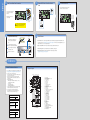
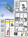
2
Minimum Hardware Requirements
Intel® Server Board S3000PT
Quick Start User's Guide
To avoid integration difficulties and possible
board damage, your system must meet the
following minimum requirements:
Place the board(s) into the chassis, making
sure that back panel I/O ports and chassis or
I/O shield openings align correctly. Verify
that server board mounting holes align
correctly with the chassis standoffs.
• Processor: Intel® Celeron® D processor,
minimum 2.4 GHz with chassis compatible
fan / heatsink
• Memory Type: Minimum of one 256-MB,
DDR2 533/667 MHz compliant unbuffered,
ECC or non-ECC, SPD SDRAM 240-pin
gold DIMM
• Power: Per board, minimum of 200 W
with 2 A of standby current, which meets the
SSI EPS 12-V specification
Thank you for buying an Intel® Server Board S3000PT.
The following information will help you integrate your
new server board into a third-party chassis.
For details on selecting a third-party chassis, please see
http://www.intel.com/go/serverbuilder and
http://support.intel.com/support/motherboards/server.
1
When installing the server board into a third-party chassis, refer
to the instructions that came with the chassis.
Install Server Board
Place the server board into the chassis as
shown below. Use the fasteners that came
with your chassis to secure the server board
to the chassis.
Prepare Chassis
Refer to the instructions that came with
your chassis for preparatory steps.
If you are not familiar with ESD (Electrostatic Discharge) procedures
used during system integration, please see the Intel® Server Board and
Server Chassis Safety Information document at
http://support.intel.com/support/motherboards/server/sb/cs-010770.htm.
3
Install Processor
A. Open the Socket Lever
Notes and Cautions
1. When unpackaging a processor, hold it by the edges to
avoid touching the pins.
2. This server board has a "zero-insertion force" socket.
If processor does not drop easily into socket, make
sure lever is in the fully open position.
B. Open the Load Plate
1 Push the lever handle down and away
1 Push the rear tab with your finger tip to bring
2 Pull the lever and open all the way.
2 Open the load plate as shown.
from the socket to release it.
the front end of the load plate up slightly.
1
1
2
Warning
Safety information: Read all the safety and
caution statements in this document before
performing any of the instructions. Also, see
the Intel® Server Board and Server Chassis
Safety Information document at:
http://support.intel.com/support/motherboards/
server/sb/cs-010770.htm
for complete safety information.
4
Install Passive Heatsink
The heatsink may have thermal interface material
(TIM) on the underside of it. Use caution so that
you do not damage the TIM. Use gloves to avoid
sharp edges.
1 If present, remove the protective film on the TIM.
If no TIM is present, evenly coat the heatsink
with a thermal compound.
Caution
5
2
Install DIMM Memory
This server board does not support DDR memory.
You must use DDR2 DIMMs to avoid possible
damage to server board DIMM sockets.
D. Install the Processor
C. Remove the Processor Protective Cover
1 Take the processor out of the box and
1
Orient the processor with the socket so that the
processor cutout matches the socket notch.
2
Install the processor as shown.
remove the protective shipping cover.
DDR2 DIMM Memory Identification
store for future use.
1
DDR2
2
diagonally, according to the
numbers shown.
4
W
FLO
AIR
Phillips*
screwdriver
4
D69382-001
*D69382-001*
Intel is a registered trademark of Intel Corporation or its subsidiaries in
the United States and other countries.
*Other names and brands may be claimed as the property of others.
Copyright © 2006, Intel Corporation. All rights reserved.
CAUTION:
Do not
over-tighten
fasteners.
Ch
Fro assi
nt s
3
3 Close the socket lever and ensure that the
load plate tab engages under the socket level
when fully closed.
2
Populate DIMMs in the order of: 1A, 1B, 2A, 2B.
3
1
TIM
plate as shown.
1
Notes and Cautions:
2
Anti-static
wrist wrap
2 With your finger, push down on the load
the way as shown.
Memory Type: Minimum of one 256-MB, DDR2
533/667 MHz compliant unbuffered, ECC or nonECC, SPD SDRAM 240-pin gold DIMM.
Securely re-tighten each
fastener again in the same
order.
2
F. Close Load Plate and Socket Lever
1 Close the load plate all
Note:
Heatsink styles
may differ.
The DIMM size, speed, and vendor must be the same
within a bank. However, the DIMM size can vary between banks. For example, Bank 1 can use two 256-MB
DIMMs and Bank 2 can use two 512-MB DIMMs.
To Install DIMMs:
For additional memory configurations, go to:
http://support.intel.com/support/motherboards/server
Memory sizing and configuration are guaranteed only
for qualified DIMMs approved by Intel.
Pr
o
So ces
ck so
et r
Tools Required
1
DDR
DIMM notch and socket bump must align as shown.
3 Lightly tighten each fastener
pull away from the load plate as shown.
2 Remove the socket protective cover and
the chassis for correct airflow.
Each heatsink has four captive fasteners and
should be tightened using the following
procedure:
1 Grasp the socket protective cover tab and
1
2 Align heatsink fins to the front and back of
Electrostatic discharge: Observe normal
Electrostatic Discharge (ESD) procedures
during system integration to avoid possible
damage to the server board and/or other
components of the system.
E. Remove Socket Protective Cover
Bank 1
Bank 2
DIMM 2A Socket
DIMM 1B Socket
DIMM 2B Socket
1
Open both DIMM socket levers.
2
Note location of alignment notch.
3
Insert DIMM, making sure the connector edge of
the DIMM aligns correctly with the slot.
4
Push down firmly on the DIMM until it snaps into
place and both levers close.
3
4
DIMM 1A Socket
1
ets
ock
MS
DIM
2
Avoid touching
gold contacts
when handling or
installing DIMMs.
Go to Side 2.
Side 2
6
7
Make Server Board Power Connections
Connect SATA Drives / Front Control Panel
Cable
8
Connect Chassis Fans
See the documentation that came with your chassis
for information on chassis fan connections.
See the documentation that came with
your chassis for power connection
information.
Connect Front
Control Panel
cable here.
System Fan 3 (8-pin)
System Fan 2 (8-pin)
System Fan 1 (8-pin)
Attach the main power connector
to the server board.
Auxiliary Fan (4-pin)
Main Power
Connector Detail
Connect SATA
data cables to
server board
here.
Note the location of the latch on each power
cable connector and align it with the matching tab on each server board socket.
9
Complete Hardware Setup
10
Network
Install Software
3
Before installing your operating system, you
must make I/O connections and plug in AC
power.
AC Power
A. Confirm BIOS Version: Look on the Server/System Management screen in the BIOS Setup Utility to determine the installed BIOS version.
Compare this to the versions at: http://support.intel.com/support/motherboards/server. If new versions are available, update the BIOS on your
system. See the BIOS readme.txt for update instructions.
NIC2
10/100/1000 Mb
NIC1
10/100/1000 Mb
1 See the documentation that came with your
chassis to complete rack or pedestal installation.
B. Configure On-board RAID via Ctrl-E: Refer to the installation instructions provided with the RAID controller.
2 Connect your keyboard, mouse, video, and
C. Install Operating System: Refer to the installation instructions provided with the operating system.
3 Connect the AC power cable last.
D. Install Operating System Drivers: Download the latest drivers from the product support website at:
http://support.intel.com/support/motherboards/server.
other I/O cables as shown.
Video
Serial A
USB 1- 2
Reference
Common Problems and Solutions
Component Layout
For a list of hardware components that have been tested with this system,
see: http://support.intel.com/support/motherboards/server/s3000PT/
The system does not boot or show video at power-on:
• Check that +12V CPU power connector is plugged in. Without this cable
the processor will not have any power.
• Beep code 4-3-2-1 means you have unrecognized or bad memory.
Remove and replace DIMMs one bank at a time to isolate which one is
causing problems.
• Remember, all DIMMs must be:
• DDR2 400/533/667 MHz compliant unbuffered, ECC or non-ECC,
SPD SDRAM 240-pin gold DIMMs.
• The same speed.
• From the same manufacturer.
• Installed beginning with DIMM 1A.
• Your power supply must provide a minimum of 200-W with 2A standby
current, which complies with the SSI EPS 12V specification.
The system sometimes works, but is exhibiting erratic behavior:
• This is typically the result of using an under-rated power supply.
Make sure you are using at least a 200-W power supply.
A
B
C D E F G
JJ
II
HH
GG
FF
EE
DD
CC
BB
AA
Y
W
H
I
J
K
L
Z
M
N
X
O
Accessories and Order Codes
1U Passive Heatsink (Intel)
AXXUPHS
Server Board SKUs
10-pack Intel® Server Board
S3000PT (horizontal power
connector)
BPTHBB
10-pack Intel® Server Board
S3000PT (vertical power
connector)
BPTVBB
P
V
U
Reference Chassis Accessories
1U Rack-mount Chassis
(Evercase*)
R913-PTS
1U Passive Heatsink
(Cooljag*)
OAK-B6
A complete list of accessories and spares can be found at:
www.intel.com/go/serverbuilder.
TS R Q
A.
B.
C.
D.
E.
F.
G.
H.
I.
J.
K.
L.
M.
N.
O.
P.
Q.
R.
S.
T.
U.
V.
W.
X.
Y.
Z.
AA.
BB.
CC.
DD.
EE.
FF.
GG.
HH.
II.
JJ.
NIC1 SP1 Flash
NIC1 RJ-45 and USB 1 and 2 Connector
NIC2 RJ-45 Connector
NIC2 SP1 EEPROM
Serial A Connector
Video Memory
VGA Connector
POST LEDs
ATI* ES1000 Video Controller
PCI-E x8 Riser Slot
BIOS Flash (SP1)
Intel® 82802 ICH7R Controller Hub
Super I/O (SIO)
Clock Generator
Intel® S3000 Memory Controller Hub (MCH)
775-Land (LGA) CPU Socket
2x7 Front Panel Header
System Fan 3 (8-pin)
System Fan 2 (8-pin)
System Fan 1 (8-pin)
2x9 Power Connector
Auxiliary Fan (4-pin)
Memory Slot DIMM 2B
Memory Slot DIMM 1B
Memory Slot DIMM 2A
Memory Slot DIMM 1A
Battery
SATA Port 2
USB 3 and 4 Header
SATA Port 1
Serial B Header
Intel® 82573E LAN Controller
Intel® AMT Firmware (NIC1) Update Jumper
Clear CMOS Jumper
Intel® 82573V LAN Controller
SMBus Connector