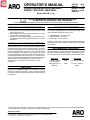
1
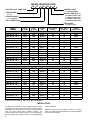
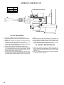
R
SECTION
M107
MANUAL
26
Released: 5-15-98
Revised: 11-20-99
49999-543
OPERATOR’S MANUAL
INCLUDING:ĂOPERATION,ĂINSTALLATIONĂ&ĂMAINTENANCE
SERIES 7 ELECTRA–FEED DRILL
Models FE074B–( )–A( )
READ THIS MANUAL CAREFULLY BEFORE INSTALLING,
OPERATING OR SERVICING THIS EQUIPMENT.
It is the responsibility of the employer to place this information in the hands of the operator. Keep for future reference.
OPERATING AND SAFETY PRECAUTIONS
•
•
Keep hands and clothing away from rotating end of tool and all
moving parts of the tool.
Wear suitable eye protection while operating tool or when
near tool when it is being operated.
Disconnect air and electrical supply from tool before removing/installing bits or performing other maintenance or service
procedures.
•
ROUTINE LUBRICATION REQUIREMENTS
When this tool was built, an “O” ring lubricant was applied to all appropriate dynamic seals to insure continued operation. Drive train
components and bearings were also supplied / filled with grease
to insure appropriate life of components. As long as all exterior
seals and wipers are maintained in good working order and all
covers and breather vents are kept in place, it is reasonable to expect that external debris will not enter the tool. It is also reasonable to expect that lubricants applied to the tool interior will require
replenishment for at least 5000 hours of normal operation.
Adding spindle oil to the power air inlet of this tool is not
necessary.
AIR SUPPLY REQUIREMENTS
For maximum operating efficiency, the following air supply specifications should be maintained to this air tool:
•
•
•
AIR PRESSURE – 90 PSIG (6 bar)
AIR FILTRATION – 50 micron
HOSE SIZE – 5/16” (8 mm) I.D.
An AROR model P29231–110 air line FILTER/REGULATOR plus
100067 gauge is recommended to maintain the above air supply
specifications.
RECOMMENDED LUBRICANTS
After disassembly is complete, all parts, except sealed or shielded
bearings, should be washed with solvent. To relubricate parts, or
for routine lubrication, use the following recommended lubricants:
Where Used
‘‘O” Rings, Lip Seals
and Air Cylinder
Sliding Splines and
Bearings
ARO Part #
36460
Description
4 oz. Stringy Lubricant
33153
5 lb. ‘‘EP” – NLGI #1
Grease
MOUNTING
Mounting clamps 49690 and 46982–1 are available for mounting
of this tool. These items are shown on page 11. Both mounts allow
the clamp to grip the outer sleeve of the tool and feature keyways
for alignment.
For parts and service information, contact your local ARO distributor, or the Customer Service Dept. of the Ingersoll–Rand Distribution
Center, White House, TN at PH: (615) 672–0321, FAX: (615) 672–0801.
ARO Tool Products
Ingersoll–Rand Company
1725 U.S. No. 1 North D P.O. Box 8000 D Southern Pines, NC 28388–8000
E1999 INGERSOLL–RAND COMPANY D PRINTED IN U.S.A.
MODEL IDENTIFICATION
FE
07
4 B– XX X –A
ELECTRIC SELF–FEED TOOL
CONTROL CODE
A – VALVE IN HEAD
HORSEPOWER
MOTOR CODE (item 11)
07 = .75
B = 49685–5 (3600 r.p.m.)
C = 49685–6 (1800 r.p.m.)
D = 49685–7 (3600 r.p.m.)
E = 49685–8 (1800 r.p.m.)
STROKE LENGTH
4 = 4” maximum
TOOL GENERATION
FREE SPEED
(see table below)
MODEL
NUMBER
FE074B–17( )–A( )
FE074B–19( )–A( )
FE074B–22( )–A( )
FE074B–24( )–A( )
FE074B–27( )–A( )
FE074B–30( )–A( )
FE074B–34( )–A( )
FE074B–38( )–A( )
FE074B–43( )–A( )
FE074B–48( )–A( )
FE074B–54( )–A( )
FE074B–59( )–A( )
FE074B–67( )–A( )
FE074B–77( )–A( )
FE074B–08( )–A( )
FE074B–10( )–A( )
FE074B–11( )–A( )
FE074B–12( )–A( )
FE074B–14( )–A( )
FE074B–15( )–A( )
FE074B–17( )–A( )
FE074B–19( )–A( )
FE074B–22( )–A( )
FE074B–24( )–A( )
FE074B–27( )–A( )
FE074B–30( )–A( )
FE074B–34( )–A( )
FE074B–38( )–A( )
R.P.M.
R.P.M.
PULLEY
# OF TEETH
# OF TEETH
@ 60 Hz
@ 50 Hz
SET
(ITEM 7)
(ITEM 12)
3600 R.P.M. MODELS (–B and –D motor code)
1684
1404
49763–1
22
47
1918
1600
49763–2
24
45
2178
1815
49763–3
26
43
2398
2000
49763–4
28
42
2700
2250
49763–5
30
40
3031
2525
49763–6
32
38
3398
2832
49763–7
34
36
3808
3173
49763–7
36
34
4274
3562
49763–6
38
32
4800
4000
49763–5
40
30
5400
4500
49763–4
42
28
5954
4961
49763–3
43
26
6750
5625
49763–2
45
24
7690
6408
49763–1
47
22
842
959
1089
1199
1350
1516
1699
1904
2137
2400
2700
2977
3375
3845
1800 R.P.M. MODELS (–C and –E motor code)
702
49763–1
22
799
49763–2
24
907
49763–3
26
999
49763–4
28
1125
49763–5
30
1263
49763–6
32
1416
49763–7
34
1587
49763–7
36
1781
49763–6
38
2000
49763–5
40
2250
49763–4
42
2481
49763–3
43
2812
49763–2
45
3204
49763–1
47
47
45
43
42
40
38
36
34
32
30
28
26
24
22
TOTAL
REDUCTION
.468:1
.533:1
.605:1
.666:1
.750:1
.842:1
.944:1
1.058:1
1.187:1
1.333:1
1.500:1
1.654:1
1.875:1
2.136:1
.468:1
.533:1
.605:1
.666:1
.750:1
.842:1
.944:1
1.058:1
1.187:1
1.333:1
1.500:1
1.654:1
1.875:1
2.136:1
MODELS WITH –EU SUFFIX ARE ‘‘EC” COMPLIANT MODELS.
INSTALLATION
The ARO model FE074B–( ) is NOT supplied with the required
motor starter. The motor starter must conform to the local / national regulations governing the use of this type of electrical equipment and must provide motor overload protection. The
recommended overload setting is given on the wiring diagram.
The power supply, motor starter and the motor nameplate ratings
2
must be equivalent.
MOTOR: The electric motor develops a minimum of .75 horsepower. The voltage requirements are shown in the following Electrical Connection Diagram.
M107
26
ELECTRICAL CONNECTION DIAGRAM
7
9
8
7
3
2
1
3
2
1
SUPPLY 220 V
SUPPLY 230 V
*(50 Hz 1.8 - 2.0 amp.)
*(60 Hz 1.6 - 2.0 amp.)
SUPPLY 440 V
SUPPLY 460 V
*(50 Hz .9 - 1.0 amp.)
*(60 Hz .8 - 1.0 amp.)
SET–UP PROCEDURE
1
2
3
LINE C
8
LINE B
9
spindle fails to rotate or rotates in the wrong direction, de–energize the motor starter immediately. Turn off the power supply and
recheck the wiring.
LINE A
4
LINE C
5
LINE B
6
LINE A
4
GROUND
5
LINE C
6
LINE B
LINE A
GROUND
3 PHASE, 50 / 60 Hz
SUPPLY 550 V
SUPPLY 575 V
*(60 Hz X.X - X.X amp.)
* RECOMMENDED OVERLOAD SETTING.
TO REVERSE ROTATION: INTERCHANGE ANY TWO LEADS.
WARNING: BE SURE THE ELECTRICAL POWER SUPPLY IS
OFF BEFORE MAKING ANY ELECTRICAL WIRING CONNECTIONS.
WARNING: FAILURE TO PROPERLY GROUND THE MOTOR
MAY CAUSE SERIOUS INJURY TO PERSONNEL.
DO NOT BLOCK THE AIR FLOW TO OR FROM THE MOTOR
COOLING FAN. DO NOT DAMAGE THE MOTOR FAN COVER.
KEEP SMALL OBJECTS CLEAR OF THE OPENINGS IN THE
FAN COVER.
Connect the motor starter to the motor as shown in the wiring diagram. The minimum wire size should be AWG No. 14, or equivalent, (4107 circular mil) and conform to local / national regulations
governing the use of this type of electrical equipment.
Once the motor is connected, turn on the power supply. If the
WARNING: Keep clear of rotating end of unit with hands and/or
clothing.
• Shut off air supply to tool.
• Loosen screw (41), releasing cover (33).
• Determine the TOTAL STROKE LENGTH the drill must travel
to perform the drilling operation.
• Loosen cap screw (28) securing yoke assembly (27) to quill
(55) and position yoke assembly on quill approximately 5/8”
(16 mm) greater distance between control valve (39) and yoke
assembly than the distance of the Total Stroke Length.
• Tighten cap screw (28), securing yoke assembly (27) to quill
(55).
• Loosen nut (29), securing cap screw (30) and turn cap screw
(30) so the distance between the head of the cap screw (30)
and control valve (39) equals the total stroke length.
• Tighten nut (29), securing cap screw (30).
• Replace cover (33), securing with screw (41).
• Attach air supply to tool.
FEED RATE CONTROL VALVES
•
•
•
•
Turn valve (103), marked ‘‘R” at side of control assembly (93),
approximately 1–1/2 turns counter–clockwise (open) from the
closed position.
Turn the other valve (103), marked ‘‘F” at side of control assembly (93), clockwise until closed (do not tighten too snugly).
Start the unit and slowly turn valve (103) marked ‘‘F” counter–
clockwise (open) until the desired forward rate of feed is
reached.
A final adjustment of the rate of return (retract) can be made
with the valve (103) marked ‘‘R”.
DISASSEMBLY/ASSEMBLY INSTRUCTIONS
•
•
•
•
•
•
•
Disconnect air and electrical supply ‘‘BEFORE” performing
maintenance or service to tool.
Never apply excessive pressure by a holding device which
may cause distortion of a part.
Apply pressure evenly to parts which have a press fit.
Apply even pressure to the bearing race that will be press
fitted to the mating part.
Use correct tools and fixtures when servicing this tool.
Don’t damage ‘‘O” rings when servicing this tool.
Use only genuine ARO replacement parts for this tool. When
ordering, specify part number, description, tool model number
and serial number.
BELT AND PULLEY SECTION DISASSEMBLY
_
_
_
_
_
_
_
Remove four screws (1), releasing cover (2).
Loosen cap screw (13), loosening tensioner assembly.
Remove belt (3).
Remove cap screws (4) and washers (5), releasing pulleys (7
and 12) and keys (6).
To remove motor (11), remove four cap screws (9).
Remove cap screw (13), releasing tensioner assembly.
To disassemble, remove retaining ring (14), releasing spring
washer (15), bearings (16) and tension wheel (17).
BELT AND PULLEY SECTION ASSEMBLY
_
_
Apply thread adhesive (Loctite 242) to threads of tension
wheel pin (18) and assemble to bracket (19).
Assemble bearing (16), tension wheel (17) and bearing (16) to
tension wheel pin (18), securing with spring washer (15) and
retaining ring (14).
_
_
_
_
_
_
_
Assemble tensioner assembly to housing (10), securing with
cap screw (13). Do not tighten cap screw.
Assemble motor (11) to housing (10), securing with four cap
screws (9).
Assemble keys (6) and pulleys (7 and 12) to spindle (23) and
motor spindle.
Apply thread adhesive (Loctite 290) to threads of cap screws
(4) and assemble screws and washers (5) to spindles, securing pulleys. NOTE: Tighten screws (4) to 50 – 60 in. lbs.
Assemble belt (3) over pulleys (7 and 12) and inside belt tensioner.
Hold tensioner assembly firmly against belt (3) and secure by
tightening cap screw (13).
Assemble cover (2) to housing, securing with four screws (1).
PULLEY SPINDLE SECTION DISASSEMBLY
_
_
_
_
_
Follow instructions for disassembly of BELT AND PULLEY
SECTION and remove belt (3) and pulley (12).
Remove four cap screws (20) and separate drive housing (10)
from frame assembly (35). NOTE: Housings will have to be
pulled apart approximately 11” (279 mm) to completely separate pulley spindle (23) from frame assembly (35).
Using a spanner type wrench, unthread and remove lock
screw (25).
Pull spindle (23) and components from housing (10).
NOTE: Bearings (21) are press fit on spindle (23). Do not remove unless it should become necessary to replace, as Brinelling of the bearing races may occur, making replacement
necessary.
3
DISASSEMBLY/ASSEMBLY INSTRUCTIONS
_
_
_
_
_
_
_
PULLEY SPINDLE SECTION ASSEMBLY
_
Assemble felt seal (24) to lock screw (25).
Assemble bearing (21) to ‘‘pulley” end of spindle (23), pressing on inner race of bearing.
Assemble spindle (23) and bearing into housing (10), pressing on outer race of bearing.
Assemble bearing spacer (22) and bearing (21) onto spindle,
pressing on inner race of bearing.
Assemble lock screw (25) to housing (10), securing spindle
and components.
Apply approximately 1/4 oz. (7 g) of ARO 33153 grease to internal splines of spindle (23) and assemble housing (10) and
components to frame assembly (35), securing with four cap
screws (20).
Refer to ‘‘BELT AND PULLEY SECTION” to complete the assembly procedure.
_
_
PISTON SECTION DISASSEMBLY
_
_
_
_
_
_
_
_
_
Loosen upper cap screw (28) on yoke assembly (27) to allow
for removal of quill (55).
Using a strap type wrench, unthread and remove outer sleeve
assembly (64) and components from the tool. NOTE: Remove
sleeve (64) with care. Pull sleeve straight away from the tool
so as not to bend the piston cylinder (63), damaging the inside
diameter.
Remove spindle nut (62) and locknut (68).
Remove spindle (58), bearing stop (60), bearings (59), spacer
(57) and bearing (56) from quill (55).
Remove quill (55) and piston cylinder (63) from sleeve. NOTE:
Handle the piston cylinder carefully to prevent damaging or
distorting the inside diameter.
Remove piston cylinder (63) from quill (55).
Remove seal (50) and unthread and remove plate nut (51), releasing plate (52) and spring washer (53).
Do not remove wiper (26) from groove in frame assembly (35),
unless damage is evident. To remove wiper (26), refer to
‘‘Pulley Spindle Section” to separate drive housing (10) from
frame assembly (35).
Remove two cap screws (32), releasing stabilizer rod (31) and
yoke assembly (27) from tool. Wiper (26) can now be removed.
PISTON SECTION ASSEMBLY
_
_
_
_
_
4
Grease wiper (26) with ARO 36460 lube and assemble to
groove in frame assembly (35). NOTE: Assemble wiper with
lips towards ‘‘chuck” end of tool.
Assemble yoke assembly (27) to stabilizer rod (31) and assemble stabilizer rod to frame assembly (35), securing with
two cap screws (32).
Refer to ‘‘Pulley Spindle Section” to assemble housing (10) to
frame assembly (35).
Grease wiper (67) with ARO 36460 lube and assemble to
groove in front bushing of outer sleeve assembly (64), with lips
of wiper facing towards sleeve (64).
Grease wipers (54) with ARO 36460 lube and assemble to
grooves in quill (55), with lips of wipers facing away from each
other.
_
_
_
_
_
_
_
_
_
_
Assemble spring washer (53) and plate (52) to quill (55), securing with plate nut (51).
Assemble square seal (50) to quill (55).
Assemble bearing (56) to spindle (58), pressing on inner race
of bearing.
Assemble spindle (58) and spacer (57) into quill (55).
Pack bearings (59) with ARO 33153 grease and assemble
onto spindle (58) and into quill (55). NOTE: Assemble bearings with open faces together (shielded sides facing out).
Assemble wiper (61) to groove in bearing stop (60), assembling with lip of wiper toward the ‘‘chuck” end of the tool.
Assemble bearing stop (60) into quill (55).
Assemble spindle nut (62) to spindle and tighten securely.
Lubricate i.d. of piston cylinder (63) and o.d. of quill (55) with
ARO 36460 lube and assemble into outer sleeve assembly
(64). Handle piston cylinder with care so as not to damage or
distort the i.d.
Assemble locknut (68) to quill (55) and tighten securely.
Grease ‘‘O” rings (48 and 49) with ARO 36460 lube and assemble to grooves in frame assembly (35).
Assemble outer sleeve assembly (64) and components to
frame assembly (35), assembling quill (55) thru yoke assembly (27). Tighten outer sleeve securely. NOTE: Use caution
when inserting quill (55) thru frame assembly so as not to
damage wiper (26).
Tighten upper cap screw (28), securing yoke assembly.
VALVE HOUSING SECTION DISASSEMBLY
_
_
_
_
_
_
Control valves (37 and 39), manifold assembly (77) and control assembly (93) can be serviced without disrupting any other section of the tool.
Remove set screws (36 and 40), releasing control valves (37
and 39).
To service bushing assembly (45), pin (44), stem (43) or
spring (42), remove outer sleeve assembly (64) and components as described in ‘‘PISTON SECTION”.
Remove three cap screws (47), releasing piston stop (46).
Remove bushing assembly (45), pin (44), stem (43) and
spring (42).
See pages 8 and 9 for disassembly and assembly of manifold
assembly (77) and control assembly (93).
VALVE HOUSING SECTION ASSEMBLY
_
_
_
_
_
_
Lubricate all ‘‘O” rings with ARO 36460 lube when assembling.
Assemble control valves (37 and 39) to frame assembly (35),
securing with set screws (36 and 40). Set screws must be air
tight.
Assemble spring (42) to stem (43) and assemble into frame
assembly.
Assemble pin (44) into bushing assembly (45) and assemble
into frame assembly.
Assemble piston stop (46) to frame assembly (tangs on magnet facing away from frame) and secure with three cap screws
(47). TIGHTEN TO 45–50 IN/LBS.
Assemble outer sleeve assembly (64) and components to tool
as described in ‘‘PISTON SECTION”.
PART NUMBER FOR ORDERING
1
2
3
4
5
6
7
8
9
10
11
12
13
14
15
16
17
18
19
20
21
22
23
24
25
26
27
28
29
30
31
32
33
34
35
36
37
38
39
40
41
42
43
44
45
46
47
48
49
50
51
52
53
54
Button Head Screw (4 req’d) . . . . . . . . . . .
Drive Housing Cover
for non–EU models . . . . . . . . . . . . . . . . . .
for –EU models . . . . . . . . . . . . . . . . . . . . .
Timing Belt . . . . . . . . . . . . . . . . . . . . . . . . . .
Cap Screw (2 req’d) (1/4” – 20 x 5/8”) . . .
Washer (2 req’d) . . . . . . . . . . . . . . . . . . . . .
Key (2 req’d) . . . . . . . . . . . . . . . . . . . . . . . .
Pulley (available only as a set, see chart)
Retaining Ring (.579” i.d.) . . . . . . . . . . . . .
Cap Screw (4 req’d) (1/4” – 20 x 3/4”) . . .
Drive Housing . . . . . . . . . . . . . . . . . . . . . . .
Electric Motor (.75 h.p., 3 phase) . . . . . . . .
Pulley (available only as a set, see chart)
Cap Screw (1/4” – 20 x 3/4”) . . . . . . . . . . .
Retaining Ring (.225” i.d.) . . . . . . . . . . . . .
Spring Washer . . . . . . . . . . . . . . . . . . . . . . .
Ball Bearing (2 req’d) . . . . . . . . . . . . . . . . .
Tension Wheel . . . . . . . . . . . . . . . . . . . . . . .
Tension Wheel Pin . . . . . . . . . . . . . . . . . . .
Tensioner Bracket . . . . . . . . . . . . . . . . . . . .
Tensioner Assembly (includes items 14
thru 19) . . . . . . . . . . . . . . . . . . . . . . . . . . . .
Cap Screw (4 req’d) (1/4” – 20 x 2–1/2”) .
Bearing (2 req’d) . . . . . . . . . . . . . . . . . . . . .
Bearing Spacer . . . . . . . . . . . . . . . . . . . . . .
Pulley Spindle . . . . . . . . . . . . . . . . . . . . . . .
Seal . . . . . . . . . . . . . . . . . . . . . . . . . . . . . . . .
Lock Screw . . . . . . . . . . . . . . . . . . . . . . . . .
Wiper . . . . . . . . . . . . . . . . . . . . . . . . . . . . . .
Yoke Assembly (includes items 28, 29
and 30) . . . . . . . . . . . . . . . . . . . . . . . . . . . .
Cap Screw (2 req’d) (1/4” – 20 x 3/4”) . . .
Nut (1/4” – 20) . . . . . . . . . . . . . . . . . . . . . . .
Cap Screw (1/4” – 20 x 1”) . . . . . . . . . . . . .
Stabilizer Rod . . . . . . . . . . . . . . . . . . . . . . .
Cap Screw (2 req’d) (#10 – 24 x 3/4”) . . .
Yoke Guard . . . . . . . . . . . . . . . . . . . . . . . . .
Check Guard . . . . . . . . . . . . . . . . . . . . . . . .
Frame Assembly (includes items 36 thru 40)
Set Screw . . . . . . . . . . . . . . . . . . . . . . . . . . .
Control Valve . . . . . . . . . . . . . . . . . . . . . . . .
Stop Pin . . . . . . . . . . . . . . . . . . . . . . . . . . . .
Control Valve . . . . . . . . . . . . . . . . . . . . . . . .
Set Screw . . . . . . . . . . . . . . . . . . . . . . . . . . .
Button Head Screw (5 req’d) . . . . . . . . . . .
Spring . . . . . . . . . . . . . . . . . . . . . . . . . . . . . .
Stem . . . . . . . . . . . . . . . . . . . . . . . . . . . . . . .
Pin . . . . . . . . . . . . . . . . . . . . . . . . . . . . . . . . .
Bushing Assembly (includes Y325–8
‘‘O” ring [1/16” x 5/16” o.d.]) . . . . . . . . . . .
Piston Stop . . . . . . . . . . . . . . . . . . . . . . . . .
Cap Screw (3 req’d) (#10 – 24 x 1/2”) . . .
‘‘O” Ring (3/32” x 2–5/8” o.d.) . . . . . . . . . .
‘‘O” Ring (1/16” x 2–1/2” o.d.) . . . . . . . . . .
Square Seal . . . . . . . . . . . . . . . . . . . . . . . . .
Plate Nut . . . . . . . . . . . . . . . . . . . . . . . . . . .
Plate . . . . . . . . . . . . . . . . . . . . . . . . . . . . . . .
Spring Washer . . . . . . . . . . . . . . . . . . . . . . .
Wiper (2 req’d) . . . . . . . . . . . . . . . . . . . . . . .
PART NUMBER FOR ORDERING
49688
49682
04333027
46923
Y99–458
46922
49673
49763–( )
Y145–22
Y99–41
49665
See chart
49763–( )
Y99–41
Y145–7
49696
49695
49669
49670
49671
49668
Y99–48
49780
49667
49643
44899
46931
49654
49662
Y99–41
Y12–4–C
Y6–45
49653
Y154-54-C
49687
49686
49646
49597
49648
49649
49648
49597
49688
49655
49661
49656
49658
49641
Y154-52-C
Y325-143
Y325–36
49642
49639
49638
49789
49633
55
56
57
58
59
60
61
62
63
64
67
68
69
70
71
72
73
74
75
76
77
78
79
80
81
82
83
84
85
86
87
88
89
90
91
92
93
94
95
96
97
98
99
100
101
102
103
104
105
106
107
108
109
110
111
112
113
Quill . . . . . . . . . . . . . . . . . . . . . . . . . . . . . . . .
Bearing . . . . . . . . . . . . . . . . . . . . . . . . . . . . .
Bearing Spacer . . . . . . . . . . . . . . . . . . . . . .
Taper Spindle . . . . . . . . . . . . . . . . . . . . . . .
Bearing (2 req’d) . . . . . . . . . . . . . . . . . . . . .
Bearing Stop . . . . . . . . . . . . . . . . . . . . . . . .
Wiper . . . . . . . . . . . . . . . . . . . . . . . . . . . . . .
Spindle Nut . . . . . . . . . . . . . . . . . . . . . . . . .
Piston Cylinder . . . . . . . . . . . . . . . . . . . . . .
Outer Sleeve Assembly . . . . . . . . . . . . . . .
Wiper . . . . . . . . . . . . . . . . . . . . . . . . . . . . . .
Locknut . . . . . . . . . . . . . . . . . . . . . . . . . . . . .
Frame Gasket . . . . . . . . . . . . . . . . . . . . . . .
Frame Plate . . . . . . . . . . . . . . . . . . . . . . . . .
Middle Gasket . . . . . . . . . . . . . . . . . . . . . . .
Middle Plate . . . . . . . . . . . . . . . . . . . . . . . . .
Manifold Gasket . . . . . . . . . . . . . . . . . . . . .
Valve Body Gasket . . . . . . . . . . . . . . . . . . .
Cap Screw (3 req’d) (#10 – 24 x 2”) . . . . .
Cap Screw (5 req’d) (#10 – 24 x 1–1/4”) .
Manifold Assembly (includes items 78
thru 92) . . . . . . . . . . . . . . . . . . . . . . . . . . . .
Cap (2 req’d) . . . . . . . . . . . . . . . . . . . . . . . .
‘‘O” Ring (2 req’d) (1/16” x 1/2” o.d.) . . . . .
Spring . . . . . . . . . . . . . . . . . . . . . . . . . . . . . .
Rubber Ball . . . . . . . . . . . . . . . . . . . . . . . . .
‘‘O” Ring (1/16” x 1/4” o.d.) . . . . . . . . . . . .
Actuator . . . . . . . . . . . . . . . . . . . . . . . . . . . .
‘‘O” Ring (1/16” x 11/32” o.d.) . . . . . . . . . .
‘‘O” Ring (1/16” x 9/32” o.d.) . . . . . . . . . . .
Needle Valve . . . . . . . . . . . . . . . . . . . . . . . .
Button Head Screw . . . . . . . . . . . . . . . . . . .
Retainer . . . . . . . . . . . . . . . . . . . . . . . . . . . .
Plug (5 req’d) . . . . . . . . . . . . . . . . . . . . . . . .
Manifold . . . . . . . . . . . . . . . . . . . . . . . . . . . .
Rubber Ball (2 req’d) . . . . . . . . . . . . . . . . .
Seat . . . . . . . . . . . . . . . . . . . . . . . . . . . . . . .
Control Assembly (includes items 94 thru
112) . . . . . . . . . . . . . . . . . . . . . . . . . . . . . . .
Retaining Ring (2 req’d) (.859” i.d.) . . . . .
End Cap (2 req’d) . . . . . . . . . . . . . . . . . . . .
‘‘O” Ring (2 req’d) (1/16” x 3/4” o.d.) . . . . .
‘‘O” Ring (2 req’d) . . . . . . . . . . . . . . . . . . . .
Spool . . . . . . . . . . . . . . . . . . . . . . . . . . . . . .
Face Plate . . . . . . . . . . . . . . . . . . . . . . . . . .
Control Valve (2 req’d) . . . . . . . . . . . . . . . .
Push Button (2 req’d) . . . . . . . . . . . . . . . . .
‘‘O” Ring (2 req’d) (1/16” x 9/32” o.d.) . . . .
Needle Valve (2 req’d) . . . . . . . . . . . . . . . .
Breather Vent (2 req’d) . . . . . . . . . . . . . . . .
Adapter . . . . . . . . . . . . . . . . . . . . . . . . . . . . .
Valve Body . . . . . . . . . . . . . . . . . . . . . . . . . .
Spring (2 req’d) . . . . . . . . . . . . . . . . . . . . . .
Rubber Ball (2 req’d) . . . . . . . . . . . . . . . . .
Seat (2 req’d) . . . . . . . . . . . . . . . . . . . . . . . .
Rubber Ball (2 req’d) . . . . . . . . . . . . . . . . .
Seat (2 req’d) . . . . . . . . . . . . . . . . . . . . . . . .
Button Head Screw (3 req’d) . . . . . . . . . . .
Seat . . . . . . . . . . . . . . . . . . . . . . . . . . . . . . .
M107
26
49630
49780
49632
49631
49779
46973–1
47504
46975–1
49637
04596045
49635
46971
49679
49680
49681
49704
49776
49705
Y154-60-C
Y154-57-C
49775
46696
Y325–12
40433
49847
Y325–6
49773
Y325–9
Y325–7
48441–1
49688
49788
59632–1
49678
44967
49774
49674
Y147–77
116212
Y325–16
116485
116207–2
49677
49648
49676
Y325–7
48441–1
20311–1
49689
49675
48304–1
49784
49777
44967
49774
49688
04596037
5
75
76
77
93
f 74
73 72
45
42
43
71
54
50
52
44
L47
70
37 69
36
46
26 25
51
53
49
48
39
40
24 41
35
29
38
30
31
28
32
33
21
27
34
68
6
67 64
63
62
61 60
59
M107
26
11
7
9
10
8
6
5
2
3
4
19
17
13
18 16
22
23
14
21
4
ASSEMBLE WITH LOCTITE 290 AND TIGHTEN TO 50 – 60 IN. LBS.
ASSEMBLE WITH LOCTITE 242.
INCLUDED IN 49595 SERVICE KIT.
20
12
6
1
5
NOT SHOWN
30131–2 WRENCH
49530 WARNING LABEL (2 REQ’D)
49684 LOGO PLATE
49791 TACK (4 REQ’D)
49883 LABEL (–EU MODELS ONLY)
04332987 DATE CODE PLATE (–EU MODELS)
04332995 DATE CODE PLATE (NON–EU MODELS)
INCLUDED IN 49594 SERVICE KIT.
f INCLUDED IN 49596 SERVICE KIT.
L TIGHTEN TO 45–50 IN/LBS.
58
15
57
56
55
#33 JACOBS TAPER
1/4–20 TH’D. x 3/4” LONG
7
49775 MANIFOLD ASSEMBLY
INCLUDED IN 49595 SERVICE KIT.
75*
* NOT INCLUDED IN ASSEMBLY
90
88
78
79
84
83
85
82
80 81 86
87
89
_
_
_
_
_
92
91
MANIFOLD ASSEMBLY
Spring (80), ball (81) and needle valve (86) can be serviced
without removing the manifold from the tool.
Unthread and remove cap (78), releasing spring (80) and ball
(81).
Remove screw (87), releasing retainer (88).
Unthread and remove needle valve (86).
To further disassemble, remove three cap screws (75), releasing manifold from the tool.
Remove cap (78), releasing actuator (83).
_
_
_
_
_
_
_
#3–56 MOUNTING HOLES
FOR OPTIONAL SOLENOID VALVES.
79 91
113
MANIFOLD DISASSEMBLY
_
78
Lubricate all ‘‘O” rings with ARO 36460 lube when assembling.
Assemble ‘‘O” rings (82 and 84) to actuator (83) and assemble
actuator into manifold, with the small diameter going into the
manifold first.
Assemble ‘‘O” rings (79) to caps (78) and assemble one cap to
manifold, securing actuator.
Assemble ball (81) and spring (80), securing with cap (78).
Assemble ‘‘O” ring (85) to groove in needle valve (86) and
thread needle valve into manifold.
Assemble retainer (88) to manifold, securing with screw (87).
Assemble manifold assembly to tool, securing with three cap
screws (75).
#3–56 MOUNTING HOLES
FOR OPTIONAL SOLENOID VALVES.
PORT ‘‘A”
DWELL
PORT ‘‘F”
PORT ‘‘E”
PORT ‘‘C”
PORT ‘‘D”
#5–40 MOUNTING HOLES
FOR OPTIONAL 49785
PRESSURE SWITCH.
PORT ``A"
PORT ``B"
PORT ``C"
PORT ``D"
PORT ``E"
PORT ``F"
DWELL
8
PORT ‘‘B”
INPUT / START (#10-32 THD.).
INPUT / EMERGENCY RETRACT (#10-32 THD).
OUTPUT / ``TOOL IS FORWARD" SIGNAL ``ON" AT FORWARD POINT OF PRESET STROKE (#10-32 THD).
OUTPUT / ``TOOL IS RETRACTED" SIGNAL ``ON" WHEN TOOL IS FULLY RETRACTED (#10-32 THD).
OUTPUT / AUX. AIR SUPPLY FURNISHES POWER AIR TO SOLENOID VALVE OPTION. SUPPLY IS ``ON" WHEN MAIN AIR INLET IS ``ON" (#10-32 THD).
OUTPUT / AUX. AIR SUPPLY FURNISHES POWER AIR TO SOLENOID VALVE OPTION. SUPPLY IS ``ON" WHEN MAIN AIR INLET IS ``ON" (#10-32 THD).
TIME CONTROL ADJUSTMENT KNOB ADJUSTS ``HESITATION" AT RETRACT POINT. TURN IN TO INCREASE TIME, TURN OUT TO DECREASE TIME.
M107
26
49674 CONTROL ASSEMBLY
76*
104
f
99
105
1/8–27 NPT
96
95
98
112
94
100
106
101
97 f
96 f
97 f
94
95
107
103
108
f
102
110
f INCLUDED IN 49596 SERVICE KIT.
* NOT INCLUDED IN ASSEMBLY
111
109
CONTROL DISASSEMBLY
_
_
_
_
_
_
Control valves (100) and needle valves (103) can be serviced
without removing the control assembly from the tool.
Remove three screws (112), releasing face plate (99).
Pull control valves (100) from valve body (106).
Unthread and remove needle valves (103).
To further disassemble, remove five cap screws (76), releasing control assembly from the tool.
Remove retaining rings (94) and end caps (95) and push
spool (98) out of valve body (106).
_
_
_
_
_
_
CONTROL ASSEMBLY
_
Lubricate all ‘‘O” rings with ARO 36460 lube when assembling.
_
_
Assemble ‘‘O” rings (96) to grooves in end caps (95).
Assemble one end cap (95) to valve body (106), securing with
retaining ring (94).
Assemble ‘‘O” rings (97) to grooves in spool (98) and assemble spool into valve body (106).
Assemble end cap (95) to valve body, securing with retaining
ring (94).
Assemble ‘‘O” rings (102) to grooves in needle valves (103)
and thread needle valves into valve body (106).
Grease ‘‘O” rings on control valves (100) and assemble into
valve body (106).
Assemble face plate (99) to valve body, securing with three
screws (112).
Assemble control assembly to tool, securing with five cap
screws (76).
FORWARD / START
PUSHBUTTON
EXHAUST, FEED CYLINDER
RETRACT / EMERGENCY
RETRACT PUSHBUTTON
MAIN AIR INLET (1/8–27 N.P.T.)
TURN ‘‘IN” TO DECREASE FEED RATE.
TURN ‘‘OUT” TO INCREASE FEED RATE.
RETRACT FEED RATE
ADJUSTMENT KNOB FORWARD FEED RATE
ADJUSTMENT KNOB 9
HYDRAULIC CHECK SET–UP
HYDRAULIC STROKE
CHECK
LENGTH
38922
1”
38922–1
2”
38922–2
3”
‘‘F” FEED CONTROL VALVE (103)
‘‘W”
‘‘Y”
‘‘X”
CAP SCREW (28)
HYDRAULIC CHECK
FEED RATE ADJUSTMENT
SET–UP PROCEDURE
•
•
•
•
•
•
•
10
Assemble hydraulic check to yoke assembly (27).
Measure the distance from the drill point to the work piece –
distance ‘‘Y”.
Distance ‘‘X” between the hydraulic check plunger and stop
pin (38) must be less than distance ‘‘Y” to prevent damage to
the drill point when it approaches the work piece.
Loosen cap screw (28) and position the hydraulic check to obtain the correct setting for distance ‘‘X”.
Tighten cap screw (28) securely before operating unit.
Increase the air flow thru the feed control valve (103) marked
‘‘F” by opening two full turns from the closed position. This will
allow the drill to advance rapidly until the plunger of the hydraulic check contacts the stop pin (38).
The hydraulic check feed rate adjustment is located at the
nameplate end. Rotate the extended end until the slot at the
end of the spindle is aligned with the number 15 on the name
•
•
plate.
Start the drill unit and the drill will advance at a rapid rate until
the plunger of the hydraulic check contacts the stop pin (38).
Slowly rotate the extended spindle of the hydraulic check
counter–clockwise toward the number zero on the nameplate
until the drill advances at the desired rate of feed.
TO CONTROL BREAKTHROUGH
•
•
Position the hydraulic check so the distance between the
plunger and the stop pin (38)(distance ‘‘X”) is less than the distance from the drill point to the opposite side of the work piece
(distance ‘‘W”).
Set–up of the self–feed drill unit will be the same as explained
in ‘‘Set–Up Procedure”, page 3.
M107
26
ACCESSORIES
$.01
1.88
(48 mm)
49690 CLAMP ASSEMBLY
3 (76 mm)
9/32" DIA. THRU C'BORE 7/16"
DIA. x DEPTH SHOWN (4 HOLES)
$.01
2.25 (57 mm)
$.005
49691 CLAMP
$.0010
4.360
mm)
2.9815 (76 mm)
(111
Y99-53 CAP SCREW (4 REQ'D)
$.01
4.78 (121 mm)
$.005
2.750 (70 mm)
45060 KEY (4 REQ'D)
$.015
1.500
(38 mm)
$.005
Y194-95 SCREW (4 REQ'D)
.218 (6 mm)
+.000
-.001
3/16 (5 mm)
.500 (13 mm)
46982–1 MOUNT ASSEMBLY
$.005
3.000
(76 mm)
$.010
3.750
(95 mm)
2.265
(58 mm)
46979-1 MOUNT
$.005
Y99-678 CAP SCREW
4.750 (121 mm)
Y99-63 CAP SCREW (2 REQ'D)
5-9/16 (141 mm)
+.002
-.000
2.985 (76 mm)
4-7/8
(124 mm)
3-9/32
(83 mm)
$.001
2.750
(70 mm)
+.005
-.000
.187 (5 mm)
$.010
1.875
(48 mm)
1/2 (13 mm)
+.0015
-.0002
.5000 (13 mm)
#10 - 24 THREAD
11
CROSS SECTION
12
PN 49999–543