1
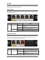
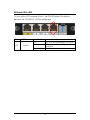
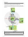
PD-Switch
Operation Manual
FCC Radio Frequency Interference Statement
This equipment has been tested and found to comply with the limits for a Class B computing device, pursuant to Part 15 of the FCC Rules.
These limits are designed to provide reasonable protection against harmful interference when the equipment is operated in a commercial
environment. This equipment generates, uses and can radiate radio frequency energy and, if not installed and used in accordance with the
instruction manual, may cause harmful interference to radio communications. Operation of this equipment in a residential area is likely to
cause harmful interference in which the user will be required to correct the interference at his own expense.
Any changes or modifications not expressly approved by the manufacturer could void the user’s authority to operate the equipment.
The use of non-shielded I/O cables may not guarantee compliance with FCC RFI limits. This digital apparatus does not exceed the Class B
limits for radio noise emission from digital apparatus set out in the Radio Interference Regulation of the Canadian Department of
Communications.
Le présent appareil numérique n’émet pas de bruits radioélectriques dépassant les limites applicables aux appareils numériques de classe B
prescrites dans le Règlement sur le brouillage radioélectrique publié par le ministère des Communications du Canada.
Warranty
IMC Networks warrants to the original end-user purchaser that this product, EXCLUSIVE OF SOFTWARE, shall be free
from defects in materials and workmanship under normal and proper use in accordance with IMC Networks' instructions
and directions for a period of six (6) years after the original date of purchase. This warranty is subject to the limitations set
forth below.
At its option, IMC Networks will repair or replace at no charge the product which proves to be defective within such
warranty period. This limited warranty shall not apply if the IMC Networks product has been damaged by unreasonable
use, accident, negligence, service or modification by anyone other than an authorized IMC Networks Service Technician
or by any other causes unrelated to defective materials or workmanship. Any replaced or repaired products or parts carry
a ninety (90) day warranty or the remainder of the initial warranty period, whichever is longer.
To receive in-warranty service, the defective product must be received at IMC Networks no later than the end of the
warranty period. The product must be accompanied by proof of purchase, satisfactory to IMC Networks, denoting
product serial number and purchase date, a written description of the defect and a Return Merchandise Authorization
(RMA) number issued by IMC Networks. No products will be accepted by IMC Networks which do not have an RMA
number. For an RMA number, contact IMC Networks at PHONE: (800) 624-1070 (in the U.S and Canada) or (949) 4653000 or FAX: (949) 465-3020. The end-user shall return the defective product to IMC Networks, freight, customs and
handling charges prepaid. End-user agrees to accept all liability for loss of or damages to the returned product during
shipment. IMC Networks shall repair or replace the returned product, at its option, and return the repaired or new
product to the end-user, freight prepaid, via method to be determined by IMC Networks. IMC Networks shall not be
liable for any costs of procurement of substitute goods, loss of profits, or any incidental, consequential, and/or special
damages of any kind resulting from a breach of any applicable express or implied warranty, breach of any obligation
arising from breach of warranty, or otherwise with respect to the manufacture and sale of any IMC Networks product,
whether or not IMC Networks has been advised of the possibility of such loss or damage.
EXCEPT FOR THE EXPRESS WARRANTY SET FORTH ABOVE, IMC NETWORKS MAKES NO OTHER WARRANTIES,
WHETHER EXPRESS OR IMPLIED, WITH RESPECT TO THIS IMC NETWORKS PRODUCT, INCLUDING WITHOUT
LIMITATION ANY SOFTWARE ASSOCIATED OR INCLUDED. IMC NETWORKS SHALL DISREGARD AND NOT BE
BOUND BY ANY REPRESENTATIONS OR WARRANTIES MADE BY ANY OTHER PERSON, INCLUDING EMPLOYEES,
DISTRIBUTORS, RESELLERS OR DEALERS OF IMC NETWORKS, WHICH ARE
INCONSISTENT WITH THE WARRANTY SET FORTH ABOVE. ALL IMPLIED WARRANTIES INCLUDING THOSE OF
MERCHANTABILITY AND FITNESS FOR A PARTICULAR PURPOSE ARE HEREBY LIMITED TO THE DURATION OF THE
EXPRESS WARRANTY STATED ABOVE.
Every reasonable effort has been made to ensure that IMC Networks product manuals and promotional materials
accurately describe IMC Networks product specifications and capabilities at the time of publication. However, because of
ongoing improvements and updating of IMC Networks products, IMC Networks cannot guarantee the accuracy of printed
materials after the date of publication and disclaims liability for changes, errors or omissions.
ii
Table of Contents
FCC Radio Frequency Interference Statement ....................................................ii
Warranty............................................................................................................ii
About the PD-Switch .........................................................................................1
Installing the PD-Switch .....................................................................................2
Port LEDs ...........................................................................................................3
Applications .......................................................................................................5
IMC Networks Technical Support.......................................................................6
Specifications .....................................................................................................6
Fiber Optic Cleaning Guidelines.........................................................................7
Electrostatic Discharge Precautions.....................................................................7
Certifications......................................................................................................8
iii
About the PD-Switch
The PD-Switch is an unmanaged Ethernet powered device (IEEE 802.3af) that allows
the port density and service area of Ethernet networks to increase. As a powered
Layer 2 device, this switch receives power over the Ethernet cable instead of using a
separate power outlet, providing Ethernet service to locations without being
constrained by the availability of power outlets. The store and forward switch
function allows the extension of Ethernet service to locations a total of 200 meters
from the Ethernet source. All RJ-45 Ports auto negotiate 10/100BaseT, full/half
duplex, and automatically configure for MDI or MDIX operation. The optional Fiber
Port is fixed at 100 Mbps full duplex.
The PD-Switch provides a variety of port configurations:
• One IEEE 802.3af PoE compatible RJ-45 port (Port 1 “PD”)
• One high-priority RJ-45 port (Port 2)
• And one of the following three configurations:
Configuration 1: Three additional RJ-45 data ports (all copper version)
Configuration 2: Two additional RJ-45 data ports and one SFP data port
Configuration 3: One additional RJ-45 data port and one Fiber-Optic data port (SFP).
Port 2 is dedicated for high priority applications. All other RJ-45 ports provide fixed
DiffServ/ToS-PRI prioritization, giving higher priority to all traffic with a VLAN TAG
with PRI>4. All RJ-45 ports incorporate the Auto Cross and Auto Negotiation
features. The Fiber-Optic configuration also includes the Far End Fault feature that
provides notification of far-end link loss on the fiber port.
1
Installing the PD-Switch
The PD-Switch is ready to use. Simply connect the appropriate data cables to ports 2
and up. Then connect the powered Ethernet cable to Port 1 (PD).
Wallmount Installation
The PD-Switch includes two X-shaped Wallmount holes in the enclosure. These
holes accommodate the use of screws to flushmount the PD-Switch to a wall.
Wall-Mounting
Holes
DIN Rail Mounting
The PD-Switch can be mounted with two DIN Rail clips, a hardware option available
through IMC Networks. The DIN Rail clips include screws, to allow the installation
onto a DIN Rail. Install the screws into DIN Rail clips, which should be mounted
perpendicular to the DIN Rail. Snap the converter onto the clips. To remove the
converter from the DIN Rail, use a flat-head screwdriver into the slot to gently pry the
converter from the rail. The DIN rail clips can be installed either on the bottom of
the PD-Switch or on the side.
NOTE
When using the side-installed location, remove the countersunk screw from the enclosure,
and then use the vacated hole for one of the DIN clip screws.
2
Port LEDs
The ports on the PD-Switch include diagnostic LEDs that indicate unique information
about the port functionality and status.
PD-Switch-TX/5
For all units with 5 copper ports, the two LEDs associated with each twisted pair port
are defined as follows:
Port
LED Name
LNK/ACT
TX
FDX
Color
Function
OFF
GREEN
No link signal detected on copper port
Glows green when a twisted pair link is
established
Activity is detected on the port
Port is operating in Half Duplex
Port is operating in Full Duplex
Flash GREEN
OFF
AMBER
PD-Switch-TX/3+FX
On units with a 1x9 fiber port, the FDX LED of port 3 has been re-defined as the “FXLNK/ACT” LED for the fiber port. Note that the “LNK” LED requires a valid Link
signal and no Far-End-Fault (FEF) from the fiber line.
Port
1X9
LED Name
LNK/ACT
Color
Function
OFF
AMBER
FEF or no link signal detected on FX port
Glows amber when the fiber link is
established
Activity is detected on the port
Flash AMBER
3
PD-Switch-TX/4+SFP
On units with an SFP transceiver at Port 5, the FDX LED of port 4 has been redefined as the “FX-LNK/ACT” LED for the fiber port.
Port
SFP
LED Name
LNK/ACT
Color
Function
OFF
AMBER
FEF or no link signal detected on SFP port
Glows amber when the SFP port link is
established
Activity is detected on the port
Flash AMBER
4
Applications
In the following example, PD-Switches have been connected to a central (PoE) PSESwitch, extending the range of the network and increasing port density.
One PD-Switch uses the standard four RJ-45 ports to connect to the network, while
the other two use the fiber and SFP configurations to extend the network beyond the
200m range.
NOTE
This product must be connected to PoE networks and is not intended for connection to
outside plant installations.
5
IMC Networks Technical Support
Tel: (949) 465-3000 or (800) 624-1070 (in the U.S. and Canada);
+32-16-550880 (Europe)
Fax: (949) 465-3020
E-Mail: [email protected]
Web: www.imcnetworks.com
Specifications
Key Features
• Broadcast Storm Protection (limited to 1% of total traffic)
• High Priority weighted queuing (10:1) to prevent port blocking
• Auto MDI/MDIX
• Flow Control on all copper ports
• Far End Fault indication on fiber ports
• 1000 MAC address learning bridge with 5 minute aging
• DiffServ/ToS and PRI aware
• Non Blocking full bandwidth Layer 2 switching core
• MAX frame size of 1916 bytes
• High priority port (2)
Industry Standards
IEEE 802.3af compliant power over Ethernet (PoE)
IEEE 802.3x Ethernet Standards
IEEE 802.3u Auto Negotiations Standards
RFC-2474 and RFC-2475 DiffServ QoS
Input Specifications
36 to 50 VDC @ 56-40mA
Operating Temperature
+32°F to +122°F (0°C to +50°C)
Storage Temperature:
-31°F to +158°F (-35°C to +70°C)
Humidity
5 to 90% (non-condensing); 0 to 10,000 ft. altitude
Dimensions
H=0.91” W=4.30” D=4.00” (2.3 x 10.9 x 10.2 cm)
6
Fiber Optic Cleaning Guidelines
Fiber Optic transmitters and receivers are extremely susceptible to contamination by
particles of dirt or dust, which can obstruct the optic path and cause performance
degradation. Good system performance requires clean optics and connector ferrules.
1.
Use fiber patch cords (or connectors, if you terminate your own fiber) only from
a reputable supplier; low-quality components can cause many hard-to-diagnose
problems in an installation.
2.
Dust caps are installed at IMC Networks to ensure factory-clean optical devices.
These protective caps should not be removed until the moment of connecting
the fiber cable to the device. Should it be necessary to disconnect the fiber
device, reinstall the protective dust caps.
3.
Store spare caps in a dust-free environment such as a sealed plastic bag or box
so that when reinstalled they do not introduce any contamination to the optics.
4.
If you suspect that the optics have been contaminated, alternate between
blasting with clean, dry, compressed air and flushing with methanol to remove
particles of dirt.
Electrostatic Discharge Precautions
Electrostatic discharge (ESD) can cause damage to any product, add-in modules or
stand alone units, containing electronic components. Always observe the following
precautions when installing or handling these kinds of products
1.
Do not remove unit from its protective packaging until ready to install.
2.
Wear an ESD wrist grounding strap before handling any module or component.
If the wrist strap is not available, maintain grounded contact with the system unit
throughout any procedure requiring ESD protection.
3.
Hold the units by the edges; do not touch the electronic components or gold
connectors.
4.
After removal, always place the boards on a grounded, static-free surface, ESD
pad or in a proper ESD bag. Do not slide the modules or stand alone units over
any surface.
WARNING! Integrated circuits and fiber optic components are
extremely susceptible to electrostatic discharge damage. Do not
handle these components directly unless you are a qualified service
technician and use tools and techniques that conform to accepted
industry practices.
7
Safety Certifications
UL/CUL: Listed to Safety of Information Technology Equipment, including Electrical
Business Equipment.
CE: The products described herein comply with the Council Directive on
Electromagnetic Compatibility (2004/108/EC) and the Council
Directive on Electrical Equipment Designed for use within Certain
Voltage Limits (2006/95/EC). Certified to Safety of Information
Technology Equipment, Including Electrical Business Equipment. For
further details, contact IMC Networks.
Class 1 Laser product, Luokan 1 Laserlaite,
Laser Klasse 1, Appareil A’Laser de Classe 1
European Directive 2002/96/EC (WEEE) requires that any equipment that bears this
symbol on product or packaging must not be disposed of with unsorted municipal
waste. This symbol indicates that the equipment should be disposed of separately
from regular household waste. It is the consumer’s responsibility to dispose of this
and all equipment so marked through designated collection facilities appointed by
government or local authorities. Following these steps through proper disposal and
recycling will help prevent potential negative consequences to the environment and
human health. For more detailed information about proper disposal, please contact
local authorities, waste disposal services, or the point of purchase for this equipment.
8
19772 Pauling • Foothill Ranch, CA 92610-2611 USA
TEL: (949) 465-3000 • FAX: (949) 465-3020
www.imcnetworks.com
© 2010 IMC Networks. All rights reserved.
The information in this document is subject to change without notice. IMC Networks assumes no responsibility for any
errors that may appear in this document. PD-Switch is a trademark of IMC Networks. Other brands or product names
may be trademarks and are the property of their respective companies.
Document Number 52-80440-00 A5
November 2010


![MN44xx4_ENG_TD_2013 [Converted].ai](http://vs1.manualzilla.com/store/data/007248699_1-a9fc65c4920ac94c5ae23bb4b2e7c043-150x150.png)