1
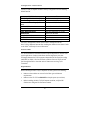
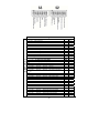
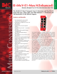
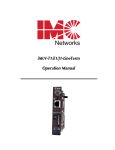
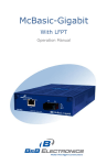
iMcV-T1/E1/J1 Repeater Operation Manual FCC Radio Frequency Interference Statement This equipment has been tested and found to comply with the limits for a Class A computing device, pursuant to Part 15 of the FCC Rules. These limits are designed to provide reasonable protection against harmful interference when the equipment is operated in a commercial environment. This equipment generates, uses and can radiate radio frequency energy and, if not installed and used in accordance with the instruction manual, may cause harmful interference to radio communications. Operation of this equipment in a residential area is likely to cause harmful interference in which the user will be required to correct the interference at his own expense. Any changes or modifications not expressly approved by the manufacturer could void the user’s authority to operate the equipment. The use of non-shielded I/O cables may not guarantee compliance with FCC RFI limits. This digital apparatus does not exceed the Class A limits for radio noise emission from digital apparatus set out in the Radio Interference Regulation of the Canadian Department of Communications. Le présent appareil numérique n’émet pas de bruits radioélectriques dépassant les limites applicables aux appareils numériques de classe A prescrites dans le Règlement sur le brouillage radioélectrique publié par le ministère des Communications du Canada. LIMITED LIFETIME WARRANTY Effective for products of B&B Electronics shipped on or after May 1, 2013, B&B Electronics warrants that each such product shall be free from defects in material and workmanship for its lifetime. This limited lifetime warranty is applicable solely to the original user and is not transferable. This warranty is expressly conditioned upon proper storage, installation, connection, operation and maintenance of products in accordance with their written specifications. Pursuant to the warranty, within the warranty period, B&B Electronics, at its option will: 1. Replace the product with a functional equivalent; 2. Repair the product; or 3. Provide a partial refund of purchase price based on a depreciated value. Products of other manufacturers sold by B&B Electronics are not subject to any warranty or indemnity offered by B&B Electronics, but may be subject to the warranties of the other manufacturers. Notwithstanding the foregoing, under no circumstances shall B&B Electronics have any warranty obligations or any other liability for: (i) any defects resulting from wear and tear, accident, improper use by the buyer or use by any third party except in accordance with the written instructions or advice of the B&B Electronics or the manufacturer of the products, including without limitation surge and overvoltage conditions that exceed specified ratings, (ii) any products which have been adjusted, modified or repaired by any party other than B&B Electronics or (iii) any descriptions, illustrations, figures as to performance, drawings and particulars of weights and dimensions contained in the B&B Electronics’ catalogs, price lists, marketing materials or elsewhere since they are merely intended to represent a general idea of the products and do not form part of this price quote and do not constitute a warranty of any kind, whether express or implied, as to any of the B&B Electronics’ products. THE REPAIR OR REPLACEMENT OF THE DEFECTIVE ITEMS IN ACCORDANCE WITH THE EXPRESS WARRANTY SET FORTH ABOVE IS B&B ELECTRONIC’ SOLE OBLIGATION UNDER THIS WARRANTY. THE WARRANTY CONTAINED IN THIS SECTION SHALL EXTEND TO THE ORIGINAL USER ONLY, IS IN LIEU OF ANY AND ALL OTHER WARRANTIES, EXPRESS OR IMPLIED, AND ALL SUCH WARRANTIES AND INDEMNITIES ARE EXPRESSLY DISCLAIMED, INCLUDING WITHOUT LIMITATION (I) THE IMPLIED WARRANTIES OF FITNESS FOR A PARTICULAR PURPOSE AND OF MERCHANTABILITY AND (II) ANY WARRANTY THAT THE PRODUCTS ARE DO NOT INFRINGE OR VIOLATE THE INTELLECTUAL PROPERTY RIGHTS OF ANY THIRD PARTY. IN NO EVENT SHALL B&B ELECTRONICS BE LIABLE FOR LOSS OF BUSINESS, LOSS OF USE OR OF DATA INTERRUPTION OF BUSINESS, LOST PROFITS OR GOODWILL OR OTHER SPECIAL, INCIDENTAL, EXEMPLARY OR CONSEQUENTIAL DAMAGES. B&B ELECTRONIC SHALL DISREGARD AND NOT BE BOUND BY ANY REPRESENTATIONS, WARRANTIES OR INDEMNITIES MADE BY ANY OTHER PERSON, INCLUDING WITHOUT LIMITATION EMPLOYEES, DISTRIBUTORS, RESELLERS OR DEALERS OF B&B ELECTRONIC WHICH ARE INCONSISTENT WITH THE WARRANTY, SET FORTH ABOVE. ii Table of Contents FCC Radio Frequency Interference Statement .............................................................. ii Warranty .........................................................................Error! Bookmark not defined. About the iMcV-T1/E1/J1 Repeater .................................................................................. 1 Installating an iMcV-T1/E1/J1 Repeater .......................................................................... 1 Configuration Instructions ................................................................................................... 2 Requirements............................................................................................................................ 2 DIP Switches .............................................................................................................................. 4 LED Operation ....................................................................................................................... 11 Troubleshooting ................................................................................................................... 16 Specifications ......................................................................................................................... 17 B&B Electronics Technical Support ................................................................................ 17 Fiber Optic Cleaning Guidelines ..................................................................................... 17 Electrostatic Discharge Precautions............................................................................... 18 Safety Certifications ............................................................................................................. 20 iii About the iMcV-T1/E1/J1 Repeater The iMcV-T1/E1/J1 Repeater chassis mounted media conversion module allows the end user to extend the distances between T1, J1, and E1 copper telephony systems by adding a fiber segment. The distances can support up to 100km depending on the module used and the fiber type available. Each iMcV-T1/E1/J1 Repeater includes one RJ-48 connector and one pair of SC or ST fiber optic connectors, which can support any fiber type in MultiMode or SingleMode. The Repeater series is also available in Single Strand Fiber, with SC connectors. Installating an iMcV-T1/E1/J1 Repeater Each module requires one slot in the chassis. To install a module, remove the blank brackets covering the slots where the module is to be installed (if present), by removing the screws on the outside edges of the bracket. Slide the module into the chassis, via the card guides, until the module is seated securely in the connector. Secure the module to the chassis by tightening the captive screw. Save any “blanks” removed during installation for future use should the configuration requirements change. Crossover/Straight-Through Connection iMcV-T1/E1/J1 Repeater comes with an RJ-48 UTP connector that features a push-button switch, located next to the port, for selecting a crossover or straightthrough connection. To select a cross-over connection, press the push-button IN. A straight-through connection is selected when the push-button is OUT. When unsure what type of connection is needed, set the push button to the position that turns the NO LNK LED off. The iMcV-T1/E1/J1 Repeater Host and Remote modules cannot be both installed in managed chassis. The recommendation, if using a managed chassis, is to install the Host in the managed chassis; the Remote Unit should be installed in an unmanaged chassis. NOTE Before installing the modules, they must be configured for Host/Remote via the DIP Switches. The Master/Slave condition requires this configuration: S3-2: ON Remote Unit Enabled (only at the REMOTE end) S3-2: OFF Remote Unit Disabled (only at the LOCAL end) 1 Configuration Instructions The iMcV-T1/E1/J1 Repeater module is factory-configured to use the following default features: T1/E1 Mode Receive Equalizer Gain Limit (EGL) Line Encoding Transmit LIU Waveshape (Buildout) Receive LIU Termination Transmit Data Source Jitter Attenuator Select Remote Unit Loopback Selection Monitor/Boost Mode NRZ Selection T1 -30 dB (Limited Long Haul) AMI (Passive Mode) DSX-1 (0 to 133 ft) 0 dB CSU Receive Side 100 ohms Enabled Standard Data Place Jitter Attenuator on TX Side Remote Unit Disabled No Loopback No Boost Disable NRZ (Passive Mode) The iView2 management software can be used to change some of the iMcV-T1/E1/J1 Repeater features after installing the modules in the chassis. Refer to the iView2 online help for more information. Passive Mode It is recommended that the default Passive mode configuration is used for most typical applications. Passive mode allows the fiber segment to pass data unchanged between the T1/E1 segments independent of the actual line coding (AMI, B8ZS, or HDB3). All errors and fault conditions from one T1/E1 end will pass through the fiber to the other end as if there were one long T1/E1 connection. Requirements Before installing the iMcV-T1/E1/J1 Repeater modules, perform the following: Make sure the modules are correct for the fiber type and distance requirements. Make sure that T1 UTP lines DO NOT use simplex power (no wet lines). Before installing the iMcV-T1/E1/J1 Repeater modules, verify the DIP Switches are configured for the feature wanted. 2 Make sure to deploy the iMcV-T1/E1/J1 Repeater modules in pairs, as Host/Remote. Make sure the Remote Chassis is not managed. Managed Modules To manage iMcV-T1/E1/J1 Repeater modules, an SNMP agent must be present; the iMediaChassis requires an SNMP management module. For a managed environment, first manually configure all of the desired DIP Switch selectable features to match what will be configured through the SNMP Management Module. NOTE Before installing the modules, they must be configured for Host/Remote via the DIP Switches. The Master/Slave condition requires this configuration: S1-10: ON Remote Unit Enabled (only at the REMOTE end) (Remote) S1-10: OFF Remote Unit Disabled (only at the LOCAL end) (Host) Use the Graphical User Interface (GUI) to enable features by using the iView2 SNMP management software. In a managed chassis, the software settings take priority over the SNMP enabled feature DIP Switch settings. Make sure that the software settings match the desired configuration requirements for the installation. iView² Management Software iView² is the B&B Electronics management software designed specifically for the B&B Electronics “iMcV” family of modules. It features a GUI and gives network managers the ability to monitor and control the manageable B&B Electronics products. iView² is available in several versions, including WebServer version 3.0, and can also function as a snap-in module for HP OpenView Network Node Manager and other third party SNMP Management software. iView2 supports the following platforms: Windows 2000 Windows XP Windows Vista Windows 7 3 Please see the SNMP Management Module installation guide for software configuration options. NOTE 2 B&B Electronics’ iView software is available for downloading from the web site: www.imcnetworks.com. Unmanaged Modules Before installing the iMcV-T1/E1/J1 Repeater module into an unmanaged chassis, configure the modules for Host/Remote Units. For further information concerning the remaining DSW support Passive Module, see the Passive Mode section of this manual. DIP Switches All iView2 enabled switches are overridden by management software. 4 Switch Settings for Switch S2 T1/E1 Selection S2-1: OFF S2-1: ON T1 Mode Selected E1 Mode Selected default Receive Equalizer Gain Limit (EGL) iVIEW2 iVIEW2 iVIEW2 iVIEW2 iVIEW2 iVIEW2 E1 S2-2: ON S2-2: OFF T1 S2-2: ON S2-2: OFF -12 dB (Short Haul) -43 dB (Long Haul) -36 dB (Long Haul) -30 dB (Limited Long Haul) SWITCH S2 Line Encoding iVIEW S2-3: ON S2-3: OFF 2 default iVIEW2 HDB3 (E1) / B8ZS (T1) AMI (Required for Passive Mode) iVIEW2 iVIEW2 default Transmit LIU Waveshape (Build-out) E1 S2-4: ON S2-4: OFF S2-4: ON S2-4: OFF Loss T1 S2-4: ON S2-4: OFF S2-4: ON S2-4: OFF S2-4: ON S2-4: OFF S2-4: ON S2-4: OFF S2-5: ON S2-5: ON S2-5: ON S2-5: ON S2-6: ON S2-6: ON S2-6: OFF S2-6: OFF 75 ohms 125 ohms 75 S ohms w/ High Return Loss 125 S ohms w/ High Return S2-5: ON S2-5: ON S2-5: OFF S2-5: OFF S2-5: ON S2-5: ON S2-5: OFF S2-5: OFF S2-6: ON S2-6: ON S2-6: ON S2-6: ON S2-6: OFF S2-6: OFF S2-6: OFF S2-6: OFF DSX-1 (0 to 133 ft) 0 dB CSU DSX-1 (133 to 266 ft) DSX-1 (266 to 399 ft) DSX-1 (399 to 533 ft) DSX-1 (533 to 655 ft) -7.5 dB CSU -15 dB CSU -22.5 dB CSU default Receive LIU Termination S2-7: ON S2-7: OFF S2-7: ON S2-7: OFF S2-8: ON S2-8: ON S2-8: OFF S2-8: OFF Receive Side Termination Disabled Receive Side 120 ohms Enabled Receive Side 100 ohms Enabled Receive Side 75 ohms Enabled 5 default Transmit Data Source iVIEW S2-9: ON S2-9: OFF S2-9: ON S2-9: OFF S2-10: ON S2-10: ON S2-10: OFF S2-10: OFF 2 Standard Data Transmit Pseudorandom Bit Sequence (PRBS) Transmit Alternating Ones and Zeros Transmit Unframed All Ones iVIEW2 iVIEW2 iVIEW2 iVIEW2 default Switch Settings for Switch S3 Jitter Attenuator Select S3-1: ON S3-1: OFF Place Jitter Attenuator on RCV Side Place Jitter Attenuator on XMT Side default Remote Unit Enabled (only at the REMOTE end) Remote Unit Disabled (only at the LOCAL end) default Remote Unit S3-2: ON S3-2: OFF SWITCH S3 Loopback Selection iVIEW S3-3: ON S3-3: OFF S3-3: ON S3-3: OFF S3-4: ON S3-4: ON S3-4: OFF S3-4: OFF 2 None Local Loopback Analog Loopback Remote Loopback iVIEW2 iVIEW2 iVIEW2 iVIEW2 default Monitor/Boost Mode S3-5: ON S3-5: OFF S3-5: ON S3-5: OFF S3-6: ON S3-6 ON S3-6 OFF S3-6 OFF NRZ Selection iVIEW S3-7: ON S3-7: OFF 2 Normal Operation (No Boost) 20 dB 26 dB 32 dB Disable NRZ (Required for Passive Mode) Enable NRZ (Line Terminating Mode) default iVIEW2 iVIEW2 default Fiber Type S3-8: Factory Configured DO NOT CHANGE S3-9: Factory Configured DO NOT CHANGE S3-10: Factory Configured DO NOT CHANGE Description of DIP Switch-Selectable Options The iMcV-T1/E1/J1 Repeater module includes DIP Switches for hardware settings for the optional features. Some of these switch options are overridden by the 6 SNMP configuration of a managed chassis (refer to the DIP Switch Table section for a list of the iView2 managed switches). The following section contains a brief description of the available options. T1/E1/J1 Mode This option allows the user to select the data rate standard that the module will use when converting: T1/J1 (default) or E1. The default is OFF, T1/J1 mode selected. Receive Equalizer Gain Limit (EGL) The copper line receiver sensitivity can be adjusted with this setting. This can be used to extend the service distance beyond the normal line length. T1 Lines Can extend the effective received signal level from -30dB to -36dB E1 Lines Can extend the effective received signal level from -12dB to -43dB The addition of this gain can extend the service distance of these lines to 2K feet. 7 Line Encoding This option allows the user to set the transmit/receive encoding for HDB3, B8ZS or AMI (default). NOTE There are currently no applications that use any other settings than AMI encoding and NRZ disabled (Passive mode). Changing the encoding setting to anything other than AMI can result in data corruption. Transmit LIU Waveshape (Line Build-out) The copper line driver for T1 applications can be adjusted to provide standard pre-distortion (LBO) of the transmitted signal for DSX1 connections. The transmitted signal level can also be reduced (-7.5dB to -22.5dB) when connecting directly to a CSU that has limited input range. For E1 circuits, the transmitter can be configured for either 75 ohm or 120 ohm drive with normal or high (21db) return loss. NOTE The receive termination resistance should match this setting. Receive LIU Termination (Line Termination) This option allows the user to set the receive termination. This is used to properly terminate cables in order to prevent signal reflections which can cause signal degradation. Transmit Data Source This option allows the user to set the module to send normal data (default) or to send specific test-patterns of data to determine problems along the cable as a diagnostic tool. The user can set the module to send a PRBS (215-1 for E1 and 220-1 for T1), an alternating ones and zeros, or an unframed all ones code, depending on the diagnostic requirements. Jitter Attenuator Select This option allows the user to select Jitter Attenuation on the UTP transmit or receive side. This decreases jitter in the data stream which increases data reliability. NOTE The jitter attenuator must always be enabled on the transmit side of the copper line. 8 Loopback Selection This option allows the user to set the Loopback location on the module. Loopback is a diagnostic tool that enables the user to test the integrity of the line by allowing the data to be looped back. The following independent loopback locations are included on the module: Analog Loopback Set this switch on the Remote module to loop the data back from the remote copper port (refer to the Remote Copper Loopback Mode section for more information). Local Loopback Set this switch on the Remote module to loop the data back from the remote fiber port (refer to the Remote Fiber Loopback Mode section for more information). Remote Loopback Set this switch on the local module to loop the data back from the local fiber port (refer to the Local Fiber Loopback Mode section for more information). Refer to the Loopback Testing section for application examples of the loopback testing modes. Remote Unit This option allows the user to enable Remote Unit on the module. The Remote Unit feature is designed to work only as the remote module of the Local/Remote pair in the required Master/Slave configuration. With Remote Unit enabled, the user can easily perform the following: • Test the line integrity of the remote copper port. • Use the Local unit to configure all SNMP-configurable features for both units. • Use the Local unit to download firmware for both units. Refer to the Module LED Functions section for more information. NOTE When the user enables the Remote Unit feature on the remote module, it is necessary to disable SNMP-management on the chassis in which the remote unit is installed (i.e. turn the iMediaChassis enter chassis SNMP switch off, or do not install an SNMP 9 Management module in either an iMe diaChassis or iMcV series chassis. 10 Monitor/Boost Mode This mode adds 20dB to 32dB of gain to the T1/E1 Receive port allowing it to be connected to standard T1/E1 passive Monitor Jacks found on most cross connect patch panels. This mode allows the unit to function as a remote monitor of an active T1 or E1 circuit. The “Trapped” active circuit can then be carried back across the fiber lien to the maintenance center for remote monitoring. NRZ (Non-Return-to-Zero) This option allows the user to enable or disable the NRZ mode. NOTE There are currently no applications that use any other settings than AMI encoding and NRZ disabled (Passive mode). Enabling NRZ can result in data corruption. Enabling NRZ terminates the line coding on the copper line. This forces the module to send raw data to the fiber line without line code information. LED Operation This section describes the LEDs and their functions. The Fiber port LED RM is the only LED that should be lit on the modules under normal operating conditions. Copper Port LEDs LPBK Glows green when the module is set to one of the Loopback modes. NO LNK Glows green when a UTP link is NOT established. PBEO Only used when the Transmit Data Source option is set to PRBS. This LED will glow amber when the iMcV-T1/E1/J1 Repeater module receives errors and will stay dark when the converter receives a PRBS without errors. Fiber Port LEDs NRZ Glows green when the NRZ mode is enabled. RM Glows green on the Remote Unit when set to DSW S3-2. Glows green on the Local unit when it has discovered a Remote management with Remote Unit enabled. NO LNK Glows green when a fiber link has NOT been established. SYM Glows amber when a 4-bit to 5-bit (4b/5b) symbol encoding error in the fiber line is detected. 11 Loopback Testing The iMcV-T1/E1/J1 Repeater includes the following loopback locations: • • • Local Remote Analog Local Loopback The Local loopback location on the module loops the fiber-receive port to the fibertransmit port. Remote Loopback The Remote loopback location on the module loops the fiber-transmit port to the fiberreceive port. Analog Loopback The Analog loopback location on the module loops the copper-transmit port to the copperreceive port. The iMcV-T1/E1/J1 Repeater can be configured to use the following loopback test modes: Local Fiber Loopback Mode This setting tests the path from the CO copper port to the Local iMcV-T1/E1/J1 Repeater module fiber port and back. Remote Fiber Loopback Mode This setting tests the path from the CO copper port to the Remote iMcV-T1/E1/J1 Repeater module fiber port and loops it back. Remote Copper Loopback This setting tests the path from the CO copper port to the Remote iMcV-T1/E1/J1 12 Mode Repeater module copper port and loops it back. The following illustrations show a typical progression of digital loopback tests; this series allows the user to individually test each segment of the conversion. To test the copper segment at the remote location requires the PRBS test described in the next section. Local Fiber Loopback Mode To set the loopback testing mode to Local Fiber Loopback Mode, perform the following: 1. Set the Local iMcV-T1/E1/J1 Repeater module to Remote Loopback (DIP Switch S3-3=Off and S3-4=Off) 2. Set the Remote iMcV-T1/E1/J1 Repeater module Loopback to None (DIP Switch S3-3=On and S3-4=On). This configuration allows the user to test the path from the CO copper port to the Local iMcV-T1/E1/J1 Repeater module fiber port and loop it back. The transmitted data is sent unhindered and the received data is ignored. Remote Fiber Loopback Mode To set the loopback testing mode to Remote Fiber Loopback Mode, perform the following: 1. Set the Local iMcV-T1/E1/J1 Repeater module Loopback to None (DIP Switch S3-3=On and S3-4=On) 2. Set the Remote iMcV-T1/E1/J1 Repeater module to Local Loopback (DIP Switch S3-3=Off and S3-4=On). This configuration allows the user to test the path from the CO copper port to the Remote iMcV-T1/E1/J1 Repeater module fiber port and loop it back. The transmitted data is sent unhindered and the received data is ignored. 13 Remote Copper Loopback Mode To set the loopback testing mode to Remote Copper Loopback Mode, perform the following: 1. Set the Local iMcV-T1/E1/J1 Repeater module Loopback to None (DIP Switch S3-3=On and S3-4=On) 2. Set the Remote iMcV-T1/E1/J1 Repeater module to Analog Loopback (DIP Switch S3-3=On and S3-4=Off). This configuration allows the user to test the path from the CO copper port to the Remote iMcV-T1/E1/J1 Repeater module copper port and loop it back. The transmitted data is sent unhindered and the received data is ignored. After the user has confirmed the integrity of these data paths, the user can activate the PRBS data generator on the Remote module and place a loopback on the customer premise equipment to test the final copper segment (refer to the Testing with PRBS section for more information). Testing with Pseudorandom Bit Sequence (PRBS) To test the copper segment from the Remote module to the Customer Premises Equipment (CPE) by using PRBS, perform the following: 1. Set the CPE to loopback the signal. 2. Set the Remote module to generate PRBSs (DIP Switch S2-9=On and S2-10=Off). 14 Check the LEDs to verify errors are not received (refer to the Module LED Functions section for more information). Fiber Optic Specifications For fiber optic specifications, visit our Web site at www.imcnetworks.com. 15 RJ-48 Pinout The following table lists the pin configuration for the RJ-48 connector. Pin 1 2 3 4 5 6 7 8 Signal Receive Ring Receive Tip No Connection Transmit Ring Transmit Tip No Connection No Connection No Connection PIN 1 Troubleshooting To test a media converter by itself, first make sure there is an appropriate fiber patch cable, then perform the following steps: 1. Connect the media converter to the T1/E1 device with a standard UTP cable. If the NO LNK LED for the copper port remains on, a valid signal is not being received. Push the crossover push button on the front of the unit. Verify that the NO LNK LED for the copper port is off. 2. Loop a single strand of fiber from the transmit port to the receive port of the media converter. Verify that the NO LNK LED for the fiber port is off. Or For single-strand fiber products, connect a single fiber cable from the Local iMcV-T1/E1/J1 Repeater to the remote iMcV-T1/E1/J1 Repeater. Verify that the NO LNK LED for the fiber port is off. NOTE iMcV-T1/E1/J1 Repeater modules cannot be connected to iMcV-T1/E1/J1 LineTerm modules successfully. 16 Specifications Power Consumption (Typical) 0.550 Amp @ 5V Operating Temperature +32°F to +122° F (0°C to +50° C) Storage Temperature -4°F to +158°F (-20°C to +70° C) Humidity 5 to 95% (non-condensing); 0 to 10,000 ft. altitude Dimensions Single Slot iMcV-Module B&B Electronics Technical Support Tel: (800) 346-3119 (in the U.S. and Canada) Monday-Friday, 7:00am-7”00pm CST +353 91 792444 (Europe) Monday through Friday 8:00am - 5:00pm GMT Fax: (815) 433-5109 E-Mail: [email protected] Web: www.bb-elec.com 17 Fiber Optic Cleaning Guidelines Fiber Optic transmitters and receivers are extremely susceptible to contamination by particles of dirt or dust, which can obstruct the optic path and cause performance degradation. Good system performance requires clean optics and connector ferrules. 1. Use fiber patch cords (or connectors, if you terminate your own fiber) only from a reputable supplier; low-quality components can cause many hard-todiagnose problems in an installation. 2. Dust caps are installed at B&B Electronics to ensure factory-clean optical devices. These protective caps should not be removed until the moment of connecting the fiber cable to the device. Should it be necessary to disconnect the fiber device, reinstall the protective dust caps. 3. Store spare caps in a dust-free environment such as a sealed plastic bag or box so that when reinstalled they do not introduce any contamination to the optics. 4. If you suspect that the optics have been contaminated, alternate between blasting with clean, dry, compressed air and flushing with methanol to remove particles of dirt. Electrostatic Discharge Precautions Electrostatic discharge (ESD) can cause damage to any product, add-in modules or stand alone units, containing electronic components. Always observe the following precautions when installing or handling these kinds of products 1. Do not remove unit from its protective packaging until ready to install. 2. Wear an ESD wrist grounding strap before handling any module or component. If the wrist strap is not available, maintain grounded contact with the system unit throughout any procedure requiring ESD protection. 3. Hold the units by the edges; do not touch the electronic components or gold connectors. 4. After removal, always place the boards on a grounded, static-free surface, ESD pad or in a proper ESD bag. Do not slide the modules or stand alone units over any surface. 18 WARNING! Integrated circuits and fiber optic components are extremely susceptible to electrostatic discharge damage. Do not handle these components directly unless you are a qualified service technician and use tools and techniques that conform to accepted industry practices. 19 Safety Certifications UL/CUL: Listed to Safety of Information Technology Equipment, including Electrical Business Equipment. Class 1 Laser product, Luokan 1 Laserlaite, Laser Klasse 1, Appareil A’Laser de Classe 1 European Directive 2002/96/EC (WEEE) requires that any equipment that bears this symbol on product or packaging must not be disposed of with unsorted municipal waste. This symbol indicates that the equipment should be disposed of separately from regular household waste. It is the consumer’s responsibility to dispose of this and all equipment so marked through designated collection facilities appointed by government or local authorities. Following these steps through proper disposal and recycling will help prevent potential negative consequences to the environment and human health. For more detailed information about proper disposal, please contact local authorities, waste disposal services, or the point of purchase for this equipment. 20 International Headquarters B&B Electronics 707 Dayton Road Ottawa, IL 61350 USA Phone (815) 433-5100 — General Fax (815) 433-5105 Website: www.bb-elec.com European Headquarters B&B Electronics Westlink Commercial Park Oranmore, Co. Galway, Ireland Phone +353 91-792444 — Fax +353 91-79244S5 Website: www.bb-elec.com © 2013 B&B Electronics. All rights reserved The information in this document is subject to change without notice. B&B Electronics assumes no responsibility for any errors that may appear in this document. iMcV-T1/E1/J1 Repeater is a trademark of B&B Electronics. Other brands or product names may be trademarks and are the property of their respective companies. Document Number 50-80200-00 B3 August 2013