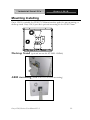
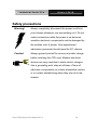
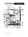
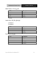
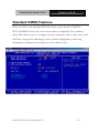
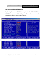
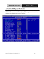
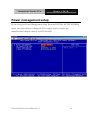
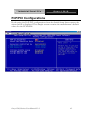
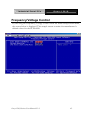
1
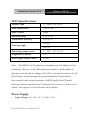
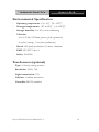
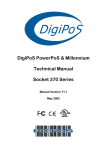
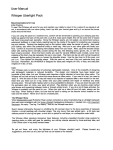
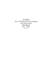
Industrial Panel PCs
Onyx-158/S
Onyx-158/S
15” LCD PC with
Expansion slot
Onyx-158/S Series User Manual V1.2
1
Industrial Panel PCs
Onyx-158/S
Copyright Notice
This document is copyrighted, 2003. All rights are reserved. The original
manufacturer reserves the right to make improvements to the products described
in this manual at any time without notice.
No part of this manual may be reproduced, copied, translated, or transmitted in
any form or by any means without the prior written permission of the original
manufacturer. Information provided in this manual is intended to be accurate and
reliable. However, the original manufacturer assumes no responsibility for its use,
nor for any infringements upon the rights of third parties, which may result from
its use.
The material is this document is for product information only and is subject to
change without notice. While reasonable efforts have been made in the
preparation of this document to assure its accuracy, AAEON, assumes no
liabilities resulting from errors or omissions in this document, or from the use of
the information contained herein.
AAEON reserves the right to make changes in the product design without notice
to its users.
Onyx-158/S Series User Manual V1.2
2
Industrial Panel PCs
Onyx-158/S
Acknowledgments
Intel and Pentium are registered trademarks of Intel® Corporation.
IBM, PC/AT, PS/2 are trademarks of International Business Machines
Corporation.
Microsoft Windows is a registered trademark of Microsoft Corporation.
RTL is a trademark of Realtek Semi-Conductor Co., Ltd.
C&T is a trademark of Chips and Technologies, Inc.
UMC is a trademark of United Microelectronics Corporation.
ITE is a trademark of Integrated Technology Express, Inc.
SiS is a trademark of Silicon Integrated Systems Corp.
VIA is a trademark of VIA Technology, Inc.
All other product names or trademarks are properties of their respective owners.
Onyx-158/S Series User Manual V1.2
3
Industrial Panel PCs
Onyx-158/S
Packing List
Before installing your Panel PC, please check if the package contains the
following items.
Onyx-158/S series Panel PC
CD-ROM
Contains User’s Manual, Drivers and Utilities
Accessories
-
Screws bag
-
Jumper packbag
-
ISA Riser card
If any of these items are missing or damaged, you should contact your distributor
or sales representative immediately.
Onyx-158/S Series User Manual V1.2
4
Industrial Panel PCs
Onyx-158/S
Safety & Warranty
1.
Read these safety instructions carefully.
2. Keep this user's manual for later reference.
3. Disconnect this equipment from any AC outlet before cleaning. Do not use
liquid or spray detergents for cleaning. Use a damp cloth.
4. For pluggable equipment, the power outlet must be installed near the
equipment and must be easily accessible.
5. Keep this equipment away from humidity.
6.
Put this equipment on a reliable surface during installation. Dropping it or
letting it fall could cause damage.
7. The openings on the enclosure are for air convection. Protect the equipment
from overheating. DO NOT COVER THE OPENINGS.
8. Make sure the voltage of the power source is correct before connecting the
equipment to the power outlet.
9. Position the power cord so that people cannot step on it. Do not place
anything over the power cord.
10. All cautions and warnings on the equipment should be noted.
11. If the equipment is not used for a long time, disconnect it from the power
source to avoid damage by transient over-voltage.
12. Never pour any liquid into an opening. This could cause fire or electrical
shock.
13.
Never open the equipment. For safety reasons, only qualified service
personnel should open the equipment.
Onyx-158/S Series User Manual V1.2
5
Industrial Panel PCs
Onyx-158/S
14. If any of the following situations arises, get the equipment checked by service
personnel:
a. The power cord or plug is damaged.
b. Liquid has penetrated into the equipment.
c. The equipment has been exposed to moisture.
d. The equipment does not work well, or you cannot get it to work
according to the users manual.
e.
The equipment has been dropped and damaged.
f.
The equipment has obvious signs of breakage.
15. DO NOT LEAVE THIS EQUIPMENT IN AN UNCONTROLLED
ENVIRONMENT WHERE THE STORAGE TEMPERATURE IS
BELOW -20° C (-4°F) OR ABOVE 60° C (140° F). IT MAY DAMAGE
THE EQUIPMENT.
Caution:
Danger of explosion if battery is incorrectly replaced. Replace
only with same or equivalent type recommended by the
manufacturer.
FCC Safety
This device complies with Part 15 FCC Rules.
Operation is subject to the following two conditions:
(1) this device may not cause harmful interference,
and (2) this device must accept any interference
received including interference that may cause
undesired operation.
Onyx-158/S Series User Manual V1.2
6
Industrial Panel PCs
Onyx-158/S
Contents
Copyright Notice ..................................................................... 2
Acknowledgments ................................................................... 3
Packing List............................................................................... 4
Safety & Warranty.................................................................... 5
Charpter 1 General Information .................................................... 9
Introductions.......................................................................... 10
Features: .................................................................................. 11
Specifications:......................................................................... 12
Dimensions............................................................................. 15
Charpter 2 Hardware Installation................................................. 16
Installing 2.5” HDD.............................................................. 17
Charpter 3 Jumper Settings ........................................................... 23
Safety precautions.................................................................. 24
CPU Card - PCM-6898 Jumper Setting.............................. 25
DOC Address Setting (J2).................................................... 29
RS-232/422/485 COM2 (JP4,JP5) Setting........................ 31
Auto detect CPU Frequency (JP7/JP8).............................. 31
System Frequency (JP9 & JP10) .......................................... 31
Clear CMOS (JP11) ............................................................... 32
Charpter 4 BIOS Installation ........................................................ 33
System test and initialization ................................................ 34
Award BIOS setup................................................................. 35
Standard CMOS Features ..................................................... 38
Advanced BIOS Features ..................................................... 39
Onyx-158/S Series User Manual V1.2
7
Industrial Panel PCs
Onyx-158/S
Advanced Chipset Features .................................................. 40
Power management setup..................................................... 42
PC Health Status.................................................................... 44
Frequency/Voltage Control ................................................. 45
Load Fail-Safe Defaults......................................................... 46
Load Optimized Defaults..................................................... 46
Set Supervisor Password....................................................... 46
Save & Exit setup................................................................... 47
Exit without saving................................................................ 47
Charpter 5 Drivers Installation ..................................................... 48
Onyx-158/S Series User Manual V1.2
8
Industrial Panel PCs
Onyx-158/S
1
Chapter
General
Information
Onyx-158/S Series User Manual V1.2
9
Industrial Panel PCs
Onyx-158/S
Introductions
The Onyx-158/S is a compact, All-in-one network compatible PC with full
safety approval and features to control a dedicated system with a wide
variety of applications. Incorporation of the Onyx-158/S into your system
can deliver both cost savings and efficiency improvements.
Common applications include point of sale systems, healthcare, interactive
information displays, control/ automation systems, common desktop use,
multimedia recreation, and other hospital requirements.
Onyx-158/S Series User Manual V1.2
10
Industrial Panel PCs
Onyx-158/S
Features:
15” high brightness color TFT LCD display
Aluminum alloy front panel
All-in-one FC Socket 370 SBC (CPU supports up to Pentium® III 1GHz,
FSB 66/100/133MHz)
Removable anti-vibration 2.5” HDD
Brightness control and Speaker with volume control on front panel
Resistive touch screen (Optional)
UL60950 safety certification
Features of PCM-6898 (All-in-one Socket 370 full-size CPU card)
Supports Socket 370 based Intel® Pentium® III / Celeron® Processor
High Speed AGP 4X for VGA display
One 10/100Base-T Fast Ethernet
Integrated AC-97 2.1
Supports CRT and 18/24/36/48-bit TFT panels (Through DVO Module)
Onyx-158/S Series User Manual V1.2
11
Industrial Panel PCs
Onyx-158/S
Specifications:
-
Construction: Heavy-duty steel chassis and aluminum alloy front panel
-
Display: 15” XGA (1024 x 768) color TFT LCD
-
CPU: Support Socket 370 based Intel® Pentium® III and Celeron® CPU,
up to 1GHz
-
Chipset: VIA VT8604 shared memory up to 32MB SDRAM
-
Memory: Support up to 512MB
-
Network (LAN): 10/100 Base-TX Ethernet port
-
Audio: VIA VT1611/1612, AC 97 2.1 Codec
-
I/O ports:
2 external serial ports: 1 x RS-232, 1 x RS-232/422/485
1 parallel port (supports EPP/ ECP)
1 PS/2 keyboard and mouse interface
Mic in/ Line in/ Line out
-
Disk Drive Housing: 2.5” HDD, slim FDD and slim DVD-ROM
-
USB connector: 2 USB ports
-
Mounting: Desktop stand
Optional: Swivel ARM
-
Expansion slots: One PCI or ISA slot
-
Power supply: Universal 90W switching power supply
-
OS Support: MS DOS, Windows 98/SE, Windows 2000, Windows XP
-
Dimension (W x H x D): 413 x 334 x 88mm (16.3” x 13.1” x 3.5”)
-
Carton Dimension (W x H x D): 556 x 516 x 335 mm (21.9” x 20.3” x
13.2”)
-
Gross Weight: 11.2Kg; 7.2Kg (without Desktop stand)
Onyx-158/S Series User Manual V1.2
12
Industrial Panel PCs
Onyx-158/S
LCD Specifications
Display type
15” color TFT LCD
Max. Resolution
1024 x 768
Max. Colors
256K
Dot size (mm)
0.33 x 0.33
Luminance (cd/m2)
250 (TYP)
Viewing angle
160°(H)
160°(V)
Operating temperature
0°~ 45℃ (32~113℉)
Brightness Control
Yes
Back Light MTBF (Hrs)
50,000
Note:
All AAEON's LCD products are manufactured with High precision
technology. However, in all LCD panels there maybe a small number of
defective pixels that do not change color. This is a normal occurrence for all
LCD displays from all manufacturers and should not be noticeable or
objectionable under normal operation. AAEON qualify the LCD panel
following industry standard: total 7 dead pixels on a screen or if there are 3
within 1 inch square area of each other on the display.
Power Supply
-
Input Voltage: 100~240V AC, 47-63Hz, 3.15A
Onyx-158/S Series User Manual V1.2
13
Industrial Panel PCs
Onyx-158/S
Environmental Specification
-
Operating temperature: 0°to 45℃ (32~122℉)
-
Storage temperature: -20°to 60℃ (-4~140℉)
-
Storage humidity: 5 to 90%, non-condensing
-
Vibration:
10 to 150 Hz, 0.075mm peak to peak (operation)
10 cycles (sweep): 1 oct/min (endurance)
-
Shock: 15G peak acceleration (11 msec. duration)
-
EMC: CE/FCC Class A
-
Safety: UL60950
Touchscreen (optional)
Type: 5/8-wire, analog resistive
Resolution: 1024 x 768
Light transmission: 75%
Lifetime: 1 million activations
Controller: RS-232 interface
Onyx-158/S Series User Manual V1.2
14
Industrial Panel PCs
Onyx-158/S
Dimensions
Unit : m
Onyx-158/S Series User Manual V1.2
15
Industrial Panel PCs
Onyx-158/S
2
Chapter
Hardware
Installation
Onyx-158/S Series User Manual V1.2
16
Industrial Panel PCs
Onyx-158/S
The panel PC is a PC-based industrial computer that is housed in aluminum alloy
front panel and heavy-duty steel chassis. You can install 2.5”HDD easily by
removing the side cover of HDD drive bay.
Removing/Installing the HDD Unit
1. Screw the 2.5” HDD on four screws.
2. Cover the four screws with silica gel as diagram.
Onyx-158/S Series User Manual V1.2
17
Industrial Panel PCs
Onyx-158/S
3. Unscrew the 7 attachment screws from the HDD drive bay.
1. Place 2.5” HDD into the drive bay and connect the IDE ribbon cable.
2. Replace the top cover of HDD drive bay and fix it with the 7 attachment
screws.
Onyx-158/S Series User Manual V1.2
18
Industrial Panel PCs
Onyx-158/S
6. Mount the drive bay into the machine by two screws.
Onyx-158/S Series User Manual V1.2
19
Industrial Panel PCs
Onyx-158/S
Removing the rear maintenance cover
1.
Remove the HDD module first then unscrew the two attachment screws
from the top cover of the desktop stand.
Caution:
Handle the desktop stand with care, since it is made of aluminum and
is weight 3kilogram.
2.
Unscrew the four attachment screws then remove the foundation of
stand.
Onyx-158/S Series User Manual V1.2
20
Industrial Panel PCs
3.
Onyx-158/S
Remove the stand holder by unscrewing the four attachment screws.
4. Unscrew the ten attachment screws used to hold the rear maintenance
cover.
5. Remove the rear maintenance cover.
Onyx-158/S Series User Manual V1.2
21
Industrial Panel PCs
Onyx-158/S
Mounting Installing
Onyx-158/S is suitable for VESA75/100mm interface pads for arm mounting or
desktop stand. Onys-158/S provides optional mounting kit for VESA75mm.
Desktop Stand (optional mount kit: STAND-158D00)
ARM mounting (ARM-LA0115 is for arm mounting)
Onyx-158/S Series User Manual V1.2
22
Industrial Panel PCs
Onyx-158/S
3
Chapter
Jumper
Settings
Onyx-158/S Series User Manual V1.2
23
Industrial Panel PCs
Onyx-158/S
Safety precautions
Warning!
Always completely disconnect the power cord from
your chassis whenever you are working on it. Do not
make connections while the power is on because
sensitive electronic components can be damaged by
the sudden rush of power. Only experienced
electronics personnel should open the PC chassis.
Caution!
Always ground yourself to remove any static charge
before touching the CPU card. Modern electronic
devices are very sensitive to static electric charges.
Use a grounding wrist strap at all times. Place all
electronic components on a static-dissipative surface
or in a static-shielded bag when they are not in the
chassis.
Onyx-158/S Series User Manual V1.2
24
Industrial Panel PCs
Onyx-158/S
CPU Card - PCM-6898 Jumper Setting
JP7
CN2
(AXT POWER)
Board Layout
JP8
CN15
J4
FAN1
CN4
J3
JP3
CN16
J1
J8
JP11
JP5
CN20
DIMM1
J9(IR)
FDD1
CN18
CN1(FDD2)
FAN2
CN19
Onyx-158/S Series User Manual V1.2
JP6
J2
CN10
IDE1
CN11
J5
CN12
PC104
CN13
(USB384)
IDE2
JP4
CN3(COM3)
CN7(COM4)
CN6(PC104)
CN8(LAN)
25
Industrial Panel PCs
Onyx-158/S
Board Dimensions
Onyx-158/S Series User Manual V1.2
26
Industrial Panel PCs
Onyx-158/S
List of Jumpers
The board has a number of jumpers that allow you to configure your
system to suit your application.
The following tables show the function of each of the board's jumpers.
Jumpers
Label
Function
J2
DOC Address Select (D800 default)
J3/4
CD_IN (2.54mm)/CD_IN (2.00mm)
J5
For PCM-3730 LAN Card Wake Up
J9
IrDA Connector
J10
Lineout function for external AMP board
J11
External LAN LED display (optional)
J12 & J13
Enabled/Disabled internal AMP chipset
JP3
VIO Select
JP4&JP5
COM2 RS-232/422/485 Select
JP6 (1-2)
Wake on LAN
JP7&JP8 (On) Autodetect CPU Frequency
JP9/JP10
CPU Frequency Select
JP11 (2-3)
Clear CMOS
Onyx-158/S Series User Manual V1.2
27
Industrial Panel PCs
Onyx-158/S
Setting Jumpers
You configure your card to match the needs of your application by setting
jumpers. A jumper is the simplest kind of electric switch. It consists of two
metal pins and a small metal clip (often protected by a plastic cover) that
slides over the pins to connect them. To “close” a jumper you connect the
pins with the clip.
To “open” a jumper you remove the clip. Sometimes a jumper will have
three pins, labeled 1, 2 and 3. In this case you would connect either pins 1
and 2 or 2 and 3.
3
1 2
Open
Closed
Closed 2-3
A pair of needle-nose pliers may be helpful when working with jumpers.
If you have any doubts about the best hardware configuration for your
application, contact your local distributor or sales representative before you
make any changes.
Generally, you simply need a standard cable to make most connections.
Onyx-158/S Series User Manual V1.2
28
Industrial Panel PCs
Onyx-158/S
DOC Address Setting (J2)
PIN
Function
1-2, 3-4
3-4
OFF
1-2
Disabled
DC00
D400
D800 *
*Default
Audio Port CD_IN (J3 & J4)
J3-2.54mm
J4-2.00mm
PIN
Function
1
2
3
4
CD-L
GND
GND
CD_R
For PCM-3730 (J5)
PIN
Function
1
2
3
4
5
5V_SB
GND
-RI
SMBDT
SMBCK
Onyx-158/S Series User Manual V1.2
29
Industrial Panel PCs
Onyx-158/S
IrDA Connector (J9)
PIN
Function
1
2
3
4
5
6
+5V
NC
IRRX
GND
IRTX
NC
VIO Select (JP3)
You can use JP3 to set the voltage input/output at 5 volts or 3.3 volts.
PIN
Function
2-3
1-2
3.3V
5V *
*Default
Wake On LAN (JP6)
PIN
Function
1-2
2-3
Enable
Disable
*Default
Onyx-158/S Series User Manual V1.2
30
Industrial Panel PCs
Onyx-158/S
RS-232/422/485 COM2 (JP4,JP5) Setting
PIN
Function
1-2
3-4
5-6
RS-232 *
RS-422
RS-485
PIN
Function
1-2, 4-5, 7-8, 10-11
2-3, 5-6, 8-9, 11-12
2-3, 5-6, 8-9, 11-12
RS-232 *
RS-422
RS-485
*Default
Auto detect CPU Frequency (JP7/JP8)
JP7
JP8
Function
On
On
AUTO
System Frequency (JP9 & JP10)
JP9
JP10
Function
On
Off
Off
On
On
Off
66MHz
100MHz
133MHz or AUTO
Onyx-158/S Series User Manual V1.2
31
Industrial Panel PCs
Onyx-158/S
Clear CMOS (JP11)
You can use JP11 to clear the CMOS data if necessary. To reset the
CMOS data, place a jumper on JP11 (Clear CMOS) for just a few seconds,
and then remove the jumper to the (Protect) position.
PIN
Function
2-3
1-2
Clear CMOS
Protect *
*Default
Onyx-158/S Series User Manual V1.2
32
Industrial Panel PCs
Onyx-158/S
4
Chapter
BIOS
Installation
Onyx-158/S Series User Manual V1.2
33
Industrial Panel PCs
Onyx-158/S
System test and initialization
These routines test and initialize board hardware. If the routines encounter an
error during the tests, you will either hear a few short beeps or see an error
message on the screen. There are two kinds of errors: fatal and non-fatal. The
system can usually continue the boot up sequence with non-fatal errors. Non-fatal
error messages usually appear on the screen along with the following instructions:
Press <F1> to RESUME
Write down the message and press the F1 key to continue the boot up sequence.
System configuration verification
These routines check the current system configuration against the values stored in
the CMOS memory. If they do not match, the program outputs an error message.
You will then need to run the BIOS setup program to set the configuration
information in memory.
There are three situations in which you will need to change the CMOS settings:
1.
You are starting your system for the first time
2.
You have changed the hardware attached to your system
3.
The CMOS memory has lost power and the configuration information
has been erased.
The PCM-6898 CMOS memory has an integral lithium battery backup for data
retention. However, you will need to replace the complete unit when it finally runs
down.
Onyx-158/S Series User Manual V1.2
34
Industrial Panel PCs
Onyx-158/S
Award BIOS setup
Awards BIOS ROM has a built-in Setup program that allows users to modify the
basic system configuration. This type of information is stored in battery-backed
CMOS RAM so that it retains the Setup information when the power is turned
off.
Entering setup
Power on the computer and press <Del> immediately. This will allow you to
enter Setup.
Standard CMOS Features
Use this menu for basic system configuration. (Date, time, IDE, etc.)
Advanced BIOS Features
Use this menu to set the advanced features available on your system.
Advanced Chipset Features
Onyx-158/S Series User Manual V1.2
35
Industrial Panel PCs
Onyx-158/S
Use this menu to change the values in the chipset registers and optimize
your system’s performance.
Integrated Peripherals
Use this menu to specify your settings for integrated peripherals. (Primary
slave, secondary slave, keyboard, mouse etc.)
Power Management Setup
Use this menu to specify your settings for power management. (HDD
power down, power on by ring, KB wake up, etc.)
PnP/PCI Configuration
This entry appears if your system supports PnP/PCI.
PC Health Status
This menu allows you to monitor the CPU temperature, CPU fan speed,
CPU voltage and system voltage for your system.
Frequency/Voltage Control
Use this menu to specify your settings for frequency/ voltage control.
Load Fail-Safe Defaults
Use this menu to load the BIOS default values for the minimal/stable
performance for your system to operate.
Load Optimized Defaults
Use this menu to load the BIOS default values that are factory settings for
optimal performance system operations. While AWARD has designated
the custom BIOS to maximize performance, the factory has the right to
change these defaults to meet their needs.
Onyx-158/S Series User Manual V1.2
36
Industrial Panel PCs
Onyx-158/S
Set Supervisor/User Password
Use this menu to set User and Supervisor Passwords.
Save and Exit Setup
Save CMOS value changes to CMOS and exit setup.
Exit Without Saving
Abandon all CMOS value changes and exit setup.
Onyx-158/S Series User Manual V1.2
37
Industrial Panel PCs
Onyx-158/S
Standard CMOS Features
When you choose the Standard CMOS Features option from the INITIAL
SETUP SCREEN menu, the screen shown below is displayed. This standard
Setup Menu allows users to configure system components such as date, time, hard
disk drive, floppy drive and display. Once a field is highlighted, on-line help
information is displayed in the right box of the Menu screen.
Onyx-158/S Series User Manual V1.2
38
Industrial Panel PCs
Onyx-158/S
Advanced BIOS Features
By choosing the Advanced BIOS Features option from the INITIAL SETUP
SCREEN menu, the screen below is displayed. This sample screen contains the
manufacturer’s default values for the PCM-6898.
Onyx-158/S Series User Manual V1.2
39
Industrial Panel PCs
Onyx-158/S
Advanced Chipset Features
By choosing the Advanced Chipset Features option from the INITIAL SETUP
SCREEN menu, the screen below is displayed. This sample screen contains the
manufacturer’s default values for the PCM-6898.
Onyx-158/S Series User Manual V1.2
40
Industrial Panel PCs
Onyx-158/S
Integrated Peripherals
By choosing the Integrated Peripherals from the INITIAL SETUP SCREEN
menu, the screen below is displayed. This sample screen contains the
manufacturer’s default values for the PCM-6898.
Onyx-158/S Series User Manual V1.2
41
Industrial Panel PCs
Onyx-158/S
Power management setup
By choosing the Power Management Setup from the INITIAL SETUP SCREEN
menu, the screen below is displayed. This sample screen contains the
manufacturer’s default values for the PCM-6898.
Onyx-158/S Series User Manual V1.2
42
Industrial Panel PCs
Onyx-158/S
PnP/PCI Configurations
By choosing the PnP/PCI configurations from the Initial Setup Screen menu, the
screen below is displayed. This sample screen contains the manufacturer’s default
values for the PCM-6898.
Onyx-158/S Series User Manual V1.2
43
Industrial Panel PCs
Onyx-158/S
PC Health Status
By choosing the PC Health Status from the Initial Setup Screen menu, the screen
below is displayed. This sample screen contains the manufacturer’s default values
for the PCM-6898.
Onyx-158/S Series User Manual V1.2
44
Industrial Panel PCs
Onyx-158/S
Frequency/Voltage Control
By choosing the Frequency/Voltage Control from the Initial Setup Screen menu,
the screen below is displayed. This sample screen contains the manufacturer’s
default values for the PCM-6898.
Onyx-158/S Series User Manual V1.2
45
Industrial Panel PCs
Onyx-158/S
Load Fail-Safe Defaults
When you press <Enter> on this item you get a confirmation dialog box with a
message similar to:
Load Fail-Safe Default (Y/N)?
Pressing "Y" loads the BIOS default values for the most stable, minimal
performance system operations.
Load Optimized Defaults
When you press <Enter> on this item you get a confirmation dialog box with a
message similar to:
Load Optimized Defaults (Y/N)?
Pressing “Y” loads the default values that are factory settings for optimal
performance system operations
Set Supervisor Password
You can set either SUPERVISOR or USER PASSWORD, or both of them. The
difference between the two is that the supervisor password allows unrestricted
access to enter and change the options of the setup menus, while the user password
only allows entry to the program, but not modify options.
To abort the process at any time, press Esc.
In the Security Option item in the BIOS Features Setup screen, select System or
Setup:
System
Enter a password each time the system boots and when-
ever you enter Setup.
Onyx-158/S Series User Manual V1.2
46
Industrial Panel PCs
Setup
Onyx-158/S
Enter a password whenever you enter Setup.
NOTE: To clear the password, simply press Enter when asked to enter a password.
Then the password function is disabled.
Save & Exit setup
If you select this option and press <Enter>, the values entered in the setup utilities
will be recorded in the chipset’s CMOS memory. The microprocessor will check this
every time you turn on your system and compare this to what it finds as it checks the
system. This record is required for the system to operate.
Exit without saving
Selecting this option and pressing <Enter> lets you exit the Setup program
without recording any new values or changing old ones.
Onyx-158/S Series User Manual V1.2
47
Industrial Panel PCs
Onyx-158/S
5
Chapter
Drivers
Installation
Onyx-158/S Series User Manual V1.2
48
Industrial Panel PCs
Onyx-158/S
The Onyx-158/S comes with a CD, which contains most of drives and utilities of
your needs.
There are several ways of installation depending on the driver package under
different Operating System application.
If you utilize Windows NT series OS, you are strongly recommended to download
the latest version Windows NT Service Pack from Microsoft website and install it
before installing any driver.
Please follow the sequence bellow to install the drivers:
Step 1 – Install VIA 4-in-1 Driver
Step 2 – Install VGA Driver
Step 3 – Install Ethernet Driver
Step 4 – Install Audio Driver
Note: For Touchscreen installation please refers to the excel file:
ReadMe_All-Prods-Touch-list.xls to find out your match touchscreen type and
follow the installation guide in respective folders.
Applicable for Windows 98/2000/XP
1.
Insert the supporting CD-ROM into drive.
2.
Click on “Start” button and then click on “Run” button, find the
installation wizard “setup.exe” in the following path:
“cd-rom”: \Driver\ CPU Board\ PCM-6898\ Step 1 – Install
VIA 4-in-1 Driver”
For Step 2, look for the respective OS folders in the following path:
“cd-rom”:\ Driver\ CPU Board\ PCM-6898\ Step 2 – Install
VGA Driver. Under the selected OS folder, find the installation
wizard “Setup.exe” button.
Again Step 3 & 4, find the installation wizard “Setup.exe” button in
Onyx-158/S Series User Manual V1.2
49
Industrial Panel PCs
Onyx-158/S
the following path:
“cd-rom”: \Driver\ CPU Board\ PCM-6898\ Step 3 – Install
Ethernet Driver”
“cd-rom”: \Driver\ CPU Board\ PCM-6898\ Step 4 – Install
Audio Driver”
Press the <Enter> key or click OK to begin the installation.
(Remarks: "cd-rom" means your CD-ROM drive letter)
3.
The setup will automatically detect your OS and complete the
installation. Simply following the step-by-step instruction.
4.
Shut down and restart your system.
Onyx-158/S Series User Manual V1.2
50