1
EVERY MACHINE IS THOROUGHLY TESTED BEFORE LEAVING THE FACTORY. EACH MACHINE IS SUPPLIED
WITH A COPY OF THIS MANUAL. OPERATORS OF THIS EQUIPMENT MUST READ AND BE FAMILIAR WITH THE
SAFETY WARNINGS. FAILURE TO OBEY WARNINGS MAY RESULT IN INJURY OR DEATH. FOLLOW INSTRUCTIONS STRICTLY TO ENSURE LONG SERVICE IN NORMAL OPERATION.
CONTENTS
Symbol Definitions....................................................................................................................................................3 - 5
Hearing Hazard Warning............................................................................................................................................... 5
Dust Warning................................................................................................................................................................. 6
Decal Descriptions and Locations............................................................................................................................ 6 - 7
Safety Warnings - DOs & DO NOTs......................................................................................................................... 8 - 9
Figures:
Figure 1....................................................................................................................................................................... 10
Figure 2....................................................................................................................................................................... 10
Figure 3....................................................................................................................................................................... 14
Figure 4....................................................................................................................................................................... 16
Instructions:
1.
Features............................................................................................................................................................. 11
2.
Benefits.............................................................................................................................................................. 11
3.
Machine Set-Up.......................................................................................................................................... 11 - 13
4.
Operating Procedure......................................................................................................................................... 13
5.
Adjustable Lockbar With Depth Linking Protection............................................................................................ 14
6.
Manual Thermal Overload................................................................................................................................. 14
7.
Recommended Extension Cords....................................................................................................................... 14
8.
Alignment Procedures................................................................................................................................ 14 - 15
9.
Profile Wheel Set-Up and Use........................................................................................................................... 15
10. Plunge Cutting................................................................................................................................................... 15
11. Maintenance Procedures................................................................................................................................... 15
12. Water Pump, Trouble Shooting Procedure........................................................................................................ 16
13. Repairs & V-Belt Tensioning with Cam Adjustment........................................................................................... 16
14. Spare Parts........................................................................................................................................................ 16
15. Tile Cutting Accessories..................................................................................................................................... 17
Wiring Diagrams...................................................................................................................................................18 - 19
Warranty...................................................................................................................................................................... 21
NOTE:
Part Numbers that have an ASTERISK (*) suffix may not be active 9-digit
numbers. The ‘542’ prefix have been added to current 6-digit part numbers and
‘0’ to 8‑digit part numbers.
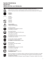
Symbol Definitions
Symboles
Definición De Los Simbolos
•
•
•
Please read the instructions for use prior to operating the machine for the first time.
Avant toute mise en service, lire attentivement la notice et se familiariser avec la machine.
Antes de la puesta en marcha, lea detenidamente las instrucciones y familiaricese con la máquina.
•
•
•
Mandatory
Obligatoire
Obligatorio
•
•
•
Indication
Indicazione
Indicación
•
•
•
Prohibition
Interdiction
Prohibición
•
•
•
Warning Triangle
Triangle d’advertissement
Triángwulo De Advertencia
•
•
•
Wear Eye Protection
Port obligatoire des lunettes de protection
Usar Gafas De Protección
•
•
•
Wear Head Protection
Port Obligatoire Du Casque Et Des Écouteurs
Usar Casco De Protección
•
•
•
Wear Breathing Protection
Port obligatoire d’un masque respiratoire protecteur
Usar Máscara De Protección
•
•
•
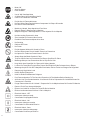
The Use Of Ear Protection Is Mandatory
Port obligatoire da casque antibruit
Es Obligatorio El Uso De Protección Auditiva
•
•
•
Wear a Hard Hat
Port Obligatoire Da Casque Antibruit
Usar Casco Duro
•
•
•
Wear Safety Shoes
Port obligatoire des chaussures de sécurité
Usar Zapatos De Seguridad
•
•
•
Wear Appropriate Clothing
Port obligatoire de la tenue appropriée
Usar Ropa Adecuada
•
•
Remove The Blade Prior To Hoisting, Loading, Unloading And Transporting The Machine On Jobsite.
Démontage Obligatoire Du Disque En Cas D’élingage, De Chargement, De Déchargement Et DeTransport Sur Le Chantier.
Desmontar El Disco Antes De Desplazar, Cargar, Descargar O Transportar La Máquina En La Obra.
•
•
•
•
Motor Off
Arrêt Du Moteur
Parar El Motor
•
•
•
Use In Well Ventilated Area
A Utiliser Dans Un Endroit Bien Ventilé
Usar En Una Área Bien Ventilada
•
•
•
Do Not Use In Flammable Areas
Ne Pas Utiliser Dans Des Ambiances Comportant Un Risque D’incendie
No Usar In Áreas Inflamables
•
•
•
Machinery Hazard, Keep Hands And Feet Clear.
Danger! Rester À Distance De La Machine
Máquina Peligrosa - Mantenga Manos Y Pies Alejados De La Máquina
•
•
•
No Non-working Personnel In Area
Zone Interdite Au Personnel Non-Ouvrier
Prohibido Para Personas Ajenas A La Obra
•
•
•
No Smoking
Défense De Fumer
No Fumar
•
•
•
Do Not Operate Without All Guards In Place
Ne Pas Utiliser Avant D’avoir Installé Toutes Les Protections
No Operar Sin Todas Las Protecciones In Su Sitio
•
•
•
Always Keep the Blade Guards In Place
Toujours Vérifier Que Les Protections De Disque Sont Bien En Place
Mantenga Siempre Las Protecciones De La Hoja En Su Sitio
•
•
•
Keep Work Area Clean/Well Lit, Remove All Safety Hazards
La Zone De Travail Doit Toujours Être Propre, Bien Éclairée Et Ne Présenter Aucun Risque
Mantenga Limpio El Sitio De Trabajo/Bien Iluminado, Elimine Todos Los Riesgos De Seguridad
•
•
•
Dangerously High Noise Level
Niveau De Bruit Dangereux
Nivel De Ruido Elevadamente Peligroso
•
•
•
Pay Extreme Attention To The Care And Protection Of The Machine Before Starting Up
Accorder Une Très Grande Attention Á La Sécurité Et À La Préparation De La Machine Avant De
Commencer À Travailler
Ponga Extrema Atención Al Cuidado Y Preparación De La Máquina Antes De Ponerla En Marcha
•
•
•
Remove Tools From Area and Machine
Enlever Les Outils De La Zone De Travail Et De La Machine
Elimine Las Herramientas Del Área Y De La Máquina
•
•
•
Electrical Switch - OFF
Interrupteur électrique-arrêt
Conmutador De Apagado Eléctrico
•
•
•
Electrical Switch - ON
Interrupteur électrique-marche
Conmutador De Encendido Eléctrico
•
•
•
Electrical Switch - Start
Interrupteur électrique-démarrage
Conmutador De Arranque Eléctrico
•
•
•
Repairs Are To Be Done By An Authorized Dealer Only
Les réparations ne peuvent être exécutées que par un distributeur agréé
Las Reparaciones Deben Ser Efectuadas Únicamente Por Un Distribuidor Autorizado
•
•
•
Diamond Blade
Disque diamanté
Sierra Diamantada
•
•
•
Blade Diameter
Diamètre De Disque
Diámetro De La Hoja
•
•
•
Pulley Diameter
Diamètre De Poulie
Diámetro De La Correa
•
•
•
Number of Revolutions Per Minute, Rotational Speed
Nombre De Tours/Minutes, Vitesse De Rotation
N° De Revoluciones Por Minuto, Velocidad De Rotación
•
•
•
Blade Flange Diameter
Diamètre Du Flasque De Disque
Diámetro De La Brida De La Hoja
•
•
•
Blade Cutting Depth
Profondeur De Coupe Du Disque
Profundidad De Corte De La Hoja
•
•
•
Machine Mass (lbs)
Poids De La Machine (en lbs)
Masa De La Máquina (lbs)
•
•
•
Electric Motor
Moteur Électrique
Motor eléctrico
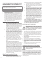
WARNING
HEARING HAZARD
DURING NORMAL USE OF THIS MACHINE, OPERATOR MAY BE EXPOSED TO A NOISE
LEVEL EQUAL OR SUPERIOR TO 85 dB (A)
ATTENZIONE!!!
RISCHIO DE LESIONE ALL’APPARATO UDITIVO
NELLE NORMALI CONDIZIONI DI UTILIZZO,
QUESTA MACCHINA PUÒ COMPORTARE PER L’OPERATORE ADDETTO UN ESPOSIZIONE
ACUSTICA DI LIVELLO PARI O SUPERIORE A
85 dB (A)
ATENCION
RIESGO DE DAÑO AUDITIVO
EN CONDICIONES NORMALES DE UTILIZACIÓN, EL OPERADOR DE ESTA MÁQUINA PUEDE
ESTAR EXPUESTO A UN NIVEL DE RUIDO IGUAL O SUPERIOR A 85 dB (A)
DUST WARNING
Cutting, especially when DRY cutting, generates dust that comes from the material being cut, which
frequently contains silica. Silica is a basic component of sand, quartz, brick clay, granite and numerous other
minerals and rocks. Exposure to excessive amount of such dust can cause:
•
•
•
Respiratory diseases (affecting your ability to breath), including chronic bronchitis, silicosis and pulmonary fibrosis from exposure to silica. These diseases may be fatal;
Skin irritation and rash; and
Cancer according to NTP* and IARC*
* National Toxicology Program, International Agency for Research on Cancer
Take precautionary steps
•
•
•
Avoid inhalation of and skin contact with dust, mist and fumes;
Wet cut when feasible, to minimize dust;
Wear and ensure that all bystanders wear appropriate respiratory protection such as dust masks designed to filter out microscopic particles. (See OSHA 29 CFR Part 1910.1200)
California Prop 65 Warning:
Use of this product can cause exposure to materials known to the State of California to cause cancer and/or birth
defects or other reproductive harm.
DECALS & LOCATIONS
ETIQUETAS Y SU UBICACIÓN
AUTOCOLLANTS ET LEURS EMPLACEMENTS
542 04 63-26*
Location: Motor Assembly
542 18 70-43*
Location: Top of Belt Guard
542 18 92-47*
Location: Elec. Motor
DECALS & LOCATIONS
ETIQUETAS Y SU UBICACIÓN
AUTOCOLLANTS ET LEURS EMPLACEMENTS
542 19 07-40 (x2)
Location: Both Sides of Pan
504 04 02-01 (x2)
Location: Front Top Corner of Blade Guard
542 19 07-36
Location: Rip Guide
542 19 07-39
Location: Front of Pan
P/N 542 04 63-27*
Location: Motor Assembly
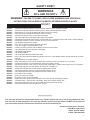
SAFETY FIRST!
WARNINGS
DO’s AND DO NOT’s
WARNING: FAILURE TO COMPLY WITH THESE WARNINGS AND OPERATING
INSTRUCTIONS COULD RESULT IN DEATH OR SERIOUS BODILY INJURY.
DO
DO
DO
DO
DO
DO
DO
DO
DO
DO
DO
DO
DO
DO
DO
DO
DO
DO
DO
DO
DO
DO
DO
DO
DO
DO
DO
DO
DO
DO
DO
DO
DO
DO
DO
DO
DO
DO
DO
DO
DO
DO
DO
DO
DO
read this entire operator’s manual before operating this machine. Understand all warnings, instructions, and controls.
keep all guards in place and in good condition.
wear safety approved hearing, eye, head and respiratory protection.
read and understand all warnings and instructions on the machine.
read and understand the symbol definitions contained in this manual.
keep all parts of your body away from the blade and all other moving parts.
know how to stop the machine quickly in case of emergency.
turn the “ON/OFF” switch to the “OFF” position prior to connecting the machine to the power source.
inspect the blade, flanges and shafts for damage before installing the blade.
use the blade flange size shown for each blade size.
use only the blade flanges supplied with the saw. Never use damaged or worn blade flanges.
use only blades marked with a maximum operating speed greater than the blade shaft speed. Verify speed by checking
blade shaft rpm and pulley diameters and blade flange diameters.
verify saw drive configuration by checking blade shaft RPM, pulley diameters, and blade flange diameter.
read all safety materials and instructions that accompany any blade used with this machine.
inspect each blade carefully before using it. If there are any signs of damage or unusual wear, DO NOT USE THE
BLADE.
mount the blade solidly and firmly. Wrench tighten the arbor nut.
make sure the blade and flanges are clean and free of dirt and debris before mounting the blade on the saw.
use the correct blade for the type of work being done. Check with blade manufacturer if you do not know if blade is correct.
use caution and follow the instructions when loading and unloading the machine.
operate this machine only in well ventilated areas.
instruct bystanders on where to stand while the machine is in operation.
establish a training program for all operators of this machine.
clear the work area of unnecessary people. Never allow anyone to stand in front of or behind the blade while the motor is
running.
make sure the blade is not contacting anything before starting the motor.
use caution when lifting and transporting this machine.
always tie down the machine when transporting.
use caution and follow instructions when setting up or transporting the machine.
have all service performed by competent service personnel.
make sure electric powered machines are plugged into a properly grounded circuit.
make sure power cords are the proper size and in good condition.
maintain a secure grip on the material being cut.
clean the water tray frequently.
verify the blade arbor hole matches the machine spindle before mounting the blade.
clean the machine after each day’s use.
follow all electrical codes in your area.
consider work area environment. Don’t expose power tools to rain. Don’t use power tools in wet locations.
use caution to guard against electric shock. Prevent body contact with grounded surfaces (i.e., pipes, radiators, ranges,
refrigerators).
use correct voltage and proper extension cords. Never carry tool by cord or yank it to disconnect it from receptacle. Keep
cord away from heat, oil and sharp edges.
always carry the machine with the motor stopped.
disconnect tools from power source when not in use, before servicing and when changing accessories.
carefully maintain and clean for better and safer performance. Follow instructions for changing accessories. Inspect tool
cords periodically and, if damaged, have repaired by authorized service facility.
only cut in a straight line.
only saw as deep as the job specifications require.
always give a copy of this manual to the equipment user. If you need extra copies, call TOLL FREE 1-800-288-5040.
SAFETY FIRST!
WARNINGS
DO’s AND DO NOT’s
WARNING: FAILURE TO COMPLY WITH THESE WARNINGS AND OPERATING
INSTRUCTIONS COULD RESULT IN DEATH OR SERIOUS BODILY INJURY.
DO NOT
DO NOT
DO NOT
DO NOT
DO NOT
DO NOT
DO NOT
DO NOT
DO NOT
DO NOT
DO NOT
DO NOT
DO NOT
DO NOT
DO NOT DO NOT DO NOT DO NOT
DO NOT
DO NOT
DO NOT
DO NOT
DO NOT
DO NOT
DO NOT
DO NOT
DO NOT
DO NOT
DO NOT
DO NOT
DO NOT
DO NOT
DO NOT
operate this machine unless you have read and understood this operator’s manual.
operate this machine without the blade guard, or other protective guards in place.
stand behind or in front of the blade path while the motor is running.
leave this machine unattended while the motor is running.
operate this machine when you are tired or fatigued.
use a wet blade without adequate water supply to the blade.
exceed maximum blade speed shown for each blade size. Excessive speed could result in blade breakage.
operate the machine if you are uncertain of how to run the machine.
use damaged equipment or blades.
touch or try to stop a moving blade with your hand.
cock, jam, wedge or twist the blade in a cut.
transport a cutting machine with the blade mounted on the machine.
use a blade that has been dropped or damaged.
use carbide tipped blades.
use abrasive blades.
use conventional abrasive blades with water.
touch a dry cutting diamond blade immediately after use. These blades require several minutes to cool after
each cut.
use damaged or worn blade flanges.
allow other persons to be near the machine when starting or when the machine is in operation.
operate this machine in an enclosed area unless it is properly vented.
operate this machine in the vicinity of anything that is flammable. Sparks could cause a fire or an explosion.
allow blade exposure from the guard to be more than 180 degrees.
operate this machine with the belt guard or blade guard removed.
operate this machine unless you are specifically trained to do so.
use a blade that has been over heated (Core has a bluish color).
jam material into the blade.
grind on the side of the blade.
lay power cords in or near the water.
replace the motor with any motor that does not have a special grounding connection.
cut deeper than 1” per pass with a dry blade. Step out to achieve deeper cuts.
start cutting with a saw until you have a clear work area and secure footing.
operate this machine while using drugs or alcohol.
*****************
This saw was designed for certain applications only. DO NOT modify this saw or use for any application other
than for which is it was designed. If you have any questions relative to its application, DO NOT use the saw until
you have written Husqvarna Construction Products and we have advised you.
Husqvarna Construction Products
17400 West 119th Street
Olathe, Kansas 66061
In USA 1-800-288-5040
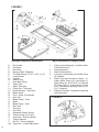
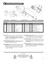
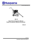
FIGURE 1
Assembly Component Identification
A.
B.
C.
D.
E.
F.
G.
H.
J.
K.
L.
L1.
L2.
M.
N.
O.
P.
Q.
R.
S.
T.
U. V.
W.
X.
Y.
Z.
AA.
10
Pan Guides
Pan Stops
Drain Plug
Bearing Cap & Fasteners
TIle Saw Wrench (15/16” x 9/16” x 1/2”)
Locking Knob
Lockbar
Water Pump
Hose Barb Fitting
Water Valve
Water Tube Assy
Fitting End - Tube Assy
Plastic Nozzles - Tube Assy
Blade Guard
Ports - Water Tube Nozzle
Arbor Nut
Blade Flange - Outer
Blade
Blade Flange - Inner
Rip Fench
Cart Stop
Set Collar
Adjustable Postion Limiter
Torsion Spring (W1 & W2)
Capscrew - Tension Adjuster
Tension Adjuster
Roll Pin - Tension Adjuster
Capscrew - Lockbar Adjustment
Major Assemblies in Shipping Carton
1.
2.
3.
4.
5.
6.
Cutting Head Assembly: Includes Water
Tube Assembly (L)}
Frame Assembly
Water Pan Assembly
Conveyor Cart Assembly (4) with Rip Fence
(S) included.
Water Pump and Accessory Carton: Includes Water Pump (H), Hose Barb (J),
Water Valve (K), 15/16”-9/16”-1/2” Wrench
(E), Drain Plug (C), Locking Knob (F) with
5/16” Flatwashers, Bearing Caps (D) w/
5/16” Fasteners.
Literature Envelope - Important to open and
read thoroughly.
FIGURE 2
I N S T R U C T I O N
INDICATION
INFORMATION
Use only blades marked with a maximum
operating speed greater than the blade shaft
speed.
Before starting up the machine, make sure
you read this entire manual and are familiar
with the operation of this machine.
PROHIBITION
WARNING
The working area must be completely clear,
well lit and all safety hazards removed.
These signs will give
advice for your safety
Before leaving our factory every machine is thoroughly
tested.
Follow our instructions strictly and your
machine will give you long service in normal
operating conditions.
1
Features
Use: Sawing of any kind of tile, up to 31” (787mm).
Diagonal on 22” x 22” (559 x 559mm) tile.
Tools: Rip Guide comes standard on all tile saws. See Tile Cutting Accessories on page 19.
(For information or availability of other accessories contact your Husqvarna supplier.)
Blade Capacity: Rim Ø 10” (254mm) - bore 5/8”
(15,9mm).
Profile Wheel: Rim Ø 6” (152mm) - bore 5/8”
(15,9mm).
Blade Rotation: Counter-Clockwise (CCW).
Depth of Cut: 3-3/4” (95mm) with 10” (254mm) blade.
Horsepower:
Voltage:
Hertz:
F.L. Amperages:
1-1/2
115
60
14.6
1-1/2
115/230
60
17.2/8.6
Blade Shaft RPM: 2760
3880
Weight: lb. (kg.)
105 (48)
110 (50)
Dimensions - L x W x H: in 51-1/4” x 26-7/16” x 225/4”
(mm) (1,302 x 671 x 575)
Conveyor Cart - L x W: in (mm) 16 x 16-1/2” (406 x
419)
Pan Holding Capacity: 12 gallons (46.1 liters)
Water Pump Output: 100 gal/hr. (378 l /hr.) Standard
300 gal/hr. (1135 i/hr.) Optional
The operator must wear
p r o t e c t i v e c l o t h i n g appropriate to the work he
is doing.
Any persons not involved in the work should
leave the area.
2
Benefits
•
The new, improved blade guard offers simplified blade
installation and removal - maximum 10” (254mm)
blade capacity. The external water tube assembly (L)
is removable for easy maintenance.
•
1-1/2 HP, High Torque (HT) 115V/60/1 motor on
standard saw.
•
The dependable, high volume, submersible coolant
pump features a screened intake.
•
The motor and pump power cords are securely
mounted directly into the motor housing.
•
The removable Drain Plug (C) at the front end of the
pan permits easy coolant draining and quick sludge
clean out. The Water Pan (2) is removable for easy
cleaning.
• The free-rolling Conveyor Cart (4) is aligned for
straight, smooth cuts. The Backstop with ruler allows
fast mounting and adjustment of the Rip Fence (S)
and optional accessories. The Cart comes standard
with a 5-1/4” end Extension for supporting longer
tile.
• Makes diagonal cuts on 22" x 22" (559 x 559 mm)
tile. Can make 31” (787mm) rip cuts.
•
Full-size belt shield and belt protection.
•
The adjustable Water Pan (2) allows the operator to
cut tile comfortably with a full view and control of work
3
Machine Set-Up
See Figure 1
•
Remove all items from the shipping carton and
identify:
1. Cutting Head Assembly (1): Includes Water Tube
Assembly (L)
2. Frame Assembly (1) with Lockbar (G) & Sprigassisted Plunge Assembly.
3. Water Pan Assembly (2)
4. Conveyor Cart Assembly {Cart Assembly (4) and
Rip Guide (S)}
5. Water Pump and Accessory Carton: Includes
Water Pump (H), Hose Barb (J), Water Valve
(K), 15/16” Wrench (E), Drain Plug (C), Locking
Knob (F) with 5/16” flatwasher, Bearing Caps (D) with 5/16” Capscrews & Flatwashers.
6. Literature Assembly Envelope
NOTE: Check the carton and all packing filler for loose
parts and optional accessories (if ordered).
11
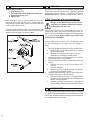
Assembly (L) from their carton. Thread the Hose Barb
(J) on the water pump outlet, hand tighten.
2. Slide the Control Valve (K) onto the flexible
plastic tubing and push the open end onto the
Hose Barb (J).
3. Set the Water Pump Assembly (5) in the deep
end of the pan beneath the belt guard. Note:
The water pump inlet screen must be submerged in order to properly pick up water.
4. Place the Water Tube Assembly (L) to the back
of the Blade Guard (M) and insert the two 1/4”
plastic nozzles (L2) into the two Ports (N) on the
side of the Blade Guard (J). Route water tubing
sa as to prevent interference with the Cart (4).
5. Insert the male plug into the Receptacle on the
motor. The Water Pump (H) will start when the
motor is turned on. For dry cutting, the water
pump should be unplugged or removed to prevent damage to the pump.
NOTE: THE MOTOR WATER PUMP OUTLET IS
NOT TO BE USED AS A GENERAL PURPOSE
CONVENIENCE OUTLET. USE FOR CONNECTION
OF THE SUPPLIED WATER PUMP ONLY.
IF ANY PARTS ARE MISSING OR DAMAGED, PLEASE
CONTACT YOUR Husqvarna CUSTOMER SERVICE
FOR INSTRUCTIONS.
CALL 1-800-288-5040
Tools required: Your new saw can be completely assembled with the Wrench (E) provided.
Qty Part Number Description
Size
1 542 16 16-41 Wrench
15/16” x 9/16” x 1/2”
•
•
Set the Frame Assembly (1) on a flat surface or on a
Husqvarna folding stand.
Install the Water Pan Assembly (2) between the four
Pan Guides (A) on the Frame Assembly (1). Locate
the Pan (2) with the Drain Plug (B) at the operating
end with the two Stops (C) located on the bottom of
the Pan (2) straddling the front leg of the Frame (1). The Water Pan Assembly (2) should slide freely back
and forth on the Guides (A) with little lateral movement. Adjust Guides if needed.
Install the Cutting Head Assembly (1):
1.
2.
3.
Set the Cutting Head Assembly (3) on the pivot
bar up between the Set Collar (U) and the adjustable Cutting Head Position Limiter (V). See
Figure 2. These components have been pre-set
at the factory to align the blade with the slot in
the center of the cart; this is adjustable.
See Alignment Procedures, section 8.
Using the 5/16” Capscrews and Lockwashers
provided, install the two Bearing Caps (D) to
the bottom of the Cutting Head (3). To secure
the Cutting Head (3) to the pivot bar, tighten the
Capscrews with a 1/2” wrench or use the Wrench
(E) provided. For plunge-cutting, leave the Bearing Caps (D) free enough to allow the Cutting
Head (3) limited movement up or down.
Insert the Locking Knob (F) with 5/16” flatwasher through the slotted Lockbar (G) into
the tapped hole in the belt guard. This is used
to set the cutting depth of the blade. See section 5.
Set-up with the Torsion Spring (W):
With the Cutting Head installed on the pivot bar,
rotate the Torsion Spring (W) until the inside
spring loop (W1) engages around the lower
edge of the motor platform. Loosen the 5/16”
Capscrew (X) in the spring Tension Adjuster
(Y) and move it to engage the Roll Pin (Z) into
the outside spring loop (W2). Set the desired
tension for your plunge cutting and tighten the
Capscrew (X) to secure the Tension Adjuster to
the pivot bar. Use the flats on the back of the
Tension Adjuster with a adjustable wrench if
extra tension is needed.
Water Pump Assembly (5) Set-up:
1.
12
Remove the Water Pump (H), Hose Barb (J),
the Water Control Valve (K) and Water Tube
WATER PUMP SAFETY GUIDELINES
Always plug the saw power cord into a GFCI
outlet when using. If a GFCI type outlet is not
available, use a plug-in type GFCI plugged
into a properly grounded outlet. Do not use
any temporary plug adapters.
•
•
•
•
•
•
•
The water pump is equipped with a ground electrical
plug, to reduce the risk of possible shock. Be sure
to connect to a properly grounded type receptacle.
Never pick the water pump up out of the water when
it is plugged in.
DO NOT EVER use the water pump to pump anything but water.
Never service the pump when it is still plugged in.
Never let the pump operate dry. It is self-cooled by
pumping water. Dry use will cause the pump to fail.
Maintain regularly and clean out debris from intake
screen.
Check the power cord for nicks or frays and never
try to alter the power cord in any way.
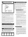
Installation & Removal of Cutting Blade:
Always set the Motor Switch to OFF prior to
mounting the blade.
Be sure you are using the correct blade for the material
being cut. For example, blades are available for cutting
materials such as wall tile, quarry tile, marble, slate and
similarly hard materials. For the best results, always
use genuine Husqvarna diamond blades. Contact your
nearest dealer to select the correct blade for your specific cutting needs.
1.
3.
4.
Raise the Blade Guard (M) to fully up and tighten
the wing nut on the side to hold it in the raised
position.
Remove the Arbor Nut (O) and the Outer Blade
Flange (P).
Check the Blade (Q) for Counter Clockwise
rotation (CCW) and install on the spindle shaft
against the Inner Blade Flange (R).
4
WARNING: Read the Operating Procedure
completely before operating your tile saw.
Take into account the working conditions
from the health and safety point of view.
Always pay extreme care and attention to the
preparation of the machine before starting.
Rotation direction is indicated by an arrow on
one side of the blade. Make sure the blade
contact surfaces are clean.
5.
6.
Install the Outer Flange (P) with the large diameter against the Blade (Q). Hand tighten
the Arbor Nut (O) with the 15/16” Wrench (E)
provided. Do not overtighten; hand tight is sufficient
Lower the Blade Guard (M) and retighten the
wing nut to securely hold the guard down in
place.
Remove all wrenches and tools from the
machine.
Always keeps blade guard in place.
•
Using the Bladeshaft Lock
An easy-to-use Bladeshaft Lock system can be used
to loosen the Arbor Nut (O). With one hand, push the
Bladeshaft lock Lever back toward the Motor while
rotating the Arbor Nut Counter Clockwise (CCW) with
the 15/16” wrench until the Lock engages the Bladeshaft. The Lock will then stay engaged, preventing
the Bladeshaft from turning while the Arbor Nut is
removed. The Lock will spring-return to the unlocked
position when Lever and Bladeshaft are released.
•
Install the Drain Plug (C) into the front end of the pan
and fill with clean water until inlet filter of water pump
is covered. See Features for capacity.
Adjust the Pan Assembly (2) to accommodate the size
of the tile to be cut and to obtain the most comfortable
position for the operator.
1. When cutting smaller tiles, adjust the pan all the
way to the rear. The operator has full view and
control of the work with minimum stretching.
2. For cutting intermediate sized tiles, such as 10”
or 12” tile, the pan can be placed somewhere
between the maximum forward and maximum
rear positions.
3. When cutting larger tiles, the pan should be
moved to the maximum forward position, thus
giving the operator the best and most comfortable position, even diagonal-cutting 22”.
4. When cutting smaller tile, adjust cart stop to
limit cart travel. When making extra long cuts
up to 31”, adjust cart stop to allow for extended
travel.
•
OPERATING PROCEDURE
•
Fill the Pan (2) with enough water to fully
submerge the water pump screen. It takes approximately 12 gallons (46 liters) to fill the Pan.
Before connecting the power cord:
*
Check the Blade Shaft Nut (O) to be sure it is
tight and that the Blade (Q) rotates freely.
WARNING: Check that the ON/OFF switch is in the
OFF position. Then connect the power cord
to a properly grounded outlet of the correct
voltage. See the decal near the power cord
for power requirements. If needed, use the
correct size three (3) conductor extension
cord to avoid excessive voltage drop. Never
use lamp cord type extensions. Refer to
the Recommended Extension Cords chart
below.
•
•
Turn the switch to ON. The blade should turn counterclockwise, when looking at the blade guard side. The
water pump will start automatically when the motor
starts. Adjustment of the water supply may be made
by means of the Control Valve(K).
Follow the blade manufacturer’s recommendations
for dry or wet cutting. Wet cutting blades can be
damaged or destroyed without sufficient water. Only
blades specifically designed for dry cutting can be
used without coolant.
The water supply should be adequate, with
water flowing on both sides of the blade. Keep
the water clean and make certain the WATER
LEVER IS ALWAYS ABOVE THE PUMP INLET.
Do not run the water pump dry!! Unplug for
dry cutting.
•
•
For straight cuts, position the tile squarely against the
back edge of the conveyor cart. Keep the cart clean
and free of cuttings. The standard Rip Guide (S) is
supplied for setting cutting lengths.
Move the conveyor cart slowly and carefully until the
blade is in contact with the tile. For best cutting, a
new blade needs a chance to “break-in” or “wear-in”
slightly. It may take several cuts to open (expose the
diamonds) of a new or closed blade.
13
5
8
ADJUSTABLE LOCKBAR WITH
DEPTH LINKING PROTECTION
ALIGNMENT PROCEDURES
Your tile saw is factory assembled and aligned prior
to shipment to ensure accurate cuts when your saw is
delivered. However, since Husqvarna cannot control
rough handling during shipping, it is suggested that the
alignment be checked. If the saw is found in need of
adjustment, refer to the appropriate section(s) below.
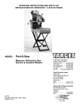
FIGURE 3
Locknut
There are two basic alignment checks for the tile saw and
any adjustments made must follow these procedures to
ensure that the unit functions freely.
A Lockbar (G) is used to set the blade depth during cutting.
The Lockbar has two (2) holes at the lower end which are
used in specific combination with the three holes in the
Frame (1). These are used as depth-limiting settings that,
if used with the correct blade diameter, will protect the
rolling cart from being cut by the blade.
Refer to the chart in Figure 3 for the correct use with a
10”, 8” or 6” blade.
The TS 250 XL is shipped standard set-up for a 10”
diameter blade. To change the setting, locate the capscrew
(AA) used as the pivot, loosen and remove the Lock Nut.
Set the Lockbar (G) to the proper holes for blade size.
Tighten the 5/16” fasteners so that the Lockbar (G) is snug
but free to pivot.
Check the setting by loosening the Knob (F) and lowering
the head fully down into the table slot. The blade segment
should be below the table surface, but not cutting into the
table. (See also Section 10, Plunge Cutting.)
6
RECOMMENDED EXTENSION
Good motor performance depends on proper
voltage. Extension cords that are too long and/
or too small in wire gauge reduce the voltage
to the motor under load. Use extension cords
no smaller than indicated below.
MOTOR F.L. AMPS 50’ Cord 75’ Cord 100’ Cord
HP RPM 115V 230V 115V 230V 115V 230V 115V 230V.
1-1/2 1725 14.6
1-1/2 3450 17.2
14
Cutting Head Adjustment (See Figure 1)
*
The Cutting Head Assembly (3) is positioned
with the Set Collar (U) against the left side of the
Motor platform and the Head Position Limiter
(V) against the inside.
*
Loosen the Set Collar (5/32” hex key), the
Position Limiter (9/16” wrench) and the four
(4) fasteners (1/2” wrench) of the Bearing Cap
(D).
*
Move the Head Assembly (3) along the Pivot Bar
of the Frame (1) until the Blade (Q) is centered
in the center slot. Locate the Set Collar (U)
against the outside of the Motor platform again
and retighten the set screw. Locate the Head
Position Limiter (V) against the inside wall of
the Motor platform, adjust to limit the Cutting
Head movement (See section 10) and tighten
the 3/8”-16 Bolt.
*
Check that the Blade is now in the center of the
middle slot. Tighten the four (4) fasteners of the
2.
Check the Parallel Alignment
*
The Conveyor Cart (4) should travel parallel to
the plane of the Blade (Q).
*
Place a Square rule against the backstop of the
Cart (4), lightly in contact with the Blade (Q). The
blade surface should be parallel to the square;
i.e., no gap between the blade and the square at
either the front or back edge of the blade. Next,
traverse the cart back and forth along the Rails.
The blade should remain parallel to the square,
staying slightly in contact with it throughout its
full travel. It should not move away from the
Blade nor should the Blade push the the Square
away. If the either happens, the Blade (Q) will
not cut straight and the Parallel Alignment must
be performed.
MANUAL THERMAL OVERLOAD
The motor is equipped with a manual overload protection
reset button. If the motors overheats, the red reset button
will “pop out” to open the motor circuit; stopping the motor
and water pump. If this occurs , the motor ON/OFF switch
must be set to OFF. After the motor cools, push in the reset
button. When it stays in, the motor can be restarted.
7
Adjustment tools required: Carpenter’s Square, two (2)
7/16” wrenches, and 5/32” hex key.
1.
Check the Blade in Slot Alignment
*
The Blade (Q) should be centered in the middle
slot of Conveyor Cart (4).
*
Set-up your saw as described above and move
the Conveyor Cart (4) back and forth from the
front to the rear of the Pan (2). If the Blade (Q)
contacts either side of the slot, the Cutting Head
Location Adjustment must be performed.
#12
8.6 #10
#10
#14 #10 #14
#8
.
#8
#14
Parallel Alignment for Sraight Cuts
The Rails determine the path the tile on the
Conveyor Cart (4) travels. For a straight cut,
the Cart must then travel ‘Parallel’ to the plane
(or side surface) of the Blade. The path of the
Conveyor Cart (4) must then be modified by
adjusting the Rails to agin be Parallel to the side
of the Blade. Slotted mounting holes in both ends
of the Water Pan (2) are provided to allow for
this adjustment.
Tip: Align only one Rail first; usually the Inner
Rail. After one Rail is aligned the other is easily
aligned using the Cart (4) as a guide. If moving
the one end of the Rail is not enough to provide
complete alignment, the other end can be moved
in the opposite direction to provide additional
Rail movement.
*
Slightly loosen all 1/4”-20 fasteners (7/16”
wrenches) locating the two Rails so that both
rails are free to move. Move one end of the
Inner Rail until the square remains flush with
the Blade while the cart is moved to and fro as
described above in Check Parallel Alignment.
Tighten the fasteners of this rail and recheck the
alignment.
*
Once alignment of one Rail has been made set
the second Rail parallel to the first. Traverse the
Cart (4) back and forth along the rails and use
it as a guide to locate the second rail parallel to
the first. Tighten the remaining 1/4”-20 fasteners
9
The TS 250 XL is designed for use with a Husqvarna® 6”
Profile Wheel, such as P/N 542 62 10-81* (3/8” Radius)
or 542 62 10‑82* (1/2” Radius).
•
•
•
10
Raise the blade guard. Remove the spindle nut
and outer flange. Remove the tile saw blade if one
has been installed. (Refer to Section 5, Adjustable
Lockbar, if needed)
Install the profile wheel onto the spindle shaft up
against the inner flange with the working surface to
the outside.
Secure into place by reversing the outer flange and
tightening the spindle nut. Lower the Blade Guard
(J) back down over the profile wheel.
Locate the material for profiling:
1. Set the edge of the part to be shaped parallel to
the wheel.
2. Locate the material under the wheel. Pull the
Conveyor Cart (4) with the material from under
the wheel to set proper cutting height.
3. Loosen the Locking Knob (F) and lower the
Cutting Head (1) so that the wheel just slightly
makes contact with the material.
4. Secure the Cutting Head (1) into position with
the Locking Knob (F) for cutting.
Note: Profiling usually takes several light passes
to produce the best results. Set lower each time
until the desire depth has been reached.
PLUNGE CUTTING
See Figures 1 & 2
Spring Force Adjustment:
Spring force can be adjusted by rotating Spring Tensioner
(Y). Loosen the 3/8”-16 Bolt (X) and rotate Spring Tensioner
(Y) to increase or decrease Spring Force. Tighten Bolt to
secure Tensioner to Pivot Shaft. It may be necessary to
slightly loosen the Bearing Caps (D) for proper and smooth
operation. By loosening Knob (F), Pivot Head can be
raised or lowered with minimal effort, depending on Spring
Force adjustment.
Limiting Cutting Head Movement:
An adjustable Head Position Limiter (V) is located on the
underside of the Head platform and is used to locate the
Blade in the center slot of the Cart and, along with the
Lockbar, as a raise and lower Position limiter for the Cutting
Head. See Cutting Head Adjustment; section 8.
11
MAINTENANCE PROCEDURES
Before performing any maintenance, ALWAYS
place the machine on a level surface with
the motor OFF and disconnect the electrical
current. Let the machine cool down!!
PROFILE WHEEL SET-UP AND USE
See Figure 1
•
5.
Your Husqvarna® tile saw is a ruggedly constructed
machine, engineered to give long, satisfactory performance.
Simple daily maintenance and care will add to the life and
productivity of your saw. After each day’s use: CLEAN
THE MACHINE!!
*
*
*
*
*
Turn off and unplug the saw before performing
any maintenance.
Keep the cart top clean and free for cuttings. To
clean it, flush the top surface and grooves with
water.
Drain, clean and refill the pan frequently. Flush
the coolant system with plenty of water, then
drain and refill the pan.
If the water flow stops, check the water pump
to see if the shaft and impeller turn freely. See
the WATER PUMP TROUBLE-SHOOTING
PROCEDURE section.
It is always good practice to clean your tile saw
after each day’s use. Drain the water and clean
out the pan. Clean the rails. Before storing, it is
good practice to wipe or spray rails with watersoluble oil (like, WD-40 or equivalent).
Entrust all repairs to your authorized dealer
only.
15
12
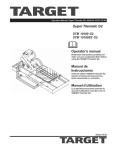
WATER PUMP TROUBLE-SHOOTING PROCEDURE
If Water Stops Flowing,
1. Stop Sawing, then
2. Disconnect Electrical Plug from Outlet, then
3. Remove the Pump, then
4. Back Flush.
Back flushing is done by forcing water into the pump
discharge and out through the screen. Most of the time
this procedure works, and the pump can be put back into
service. (See Figure below)
If the back flushing does not work, remove the screen and
turn the impeller manually, looking for and rinsing out the
impeller cavity of any dirt or foreign matter.
13
REPAIRS
We carry out all repairs in the shortest possible time
and at the most economical prices. (See front page for.
address and phone numbers) Contact your authorized
Husqvarna® dealer concerning maintenance and re-
V-Belt Tensioning with Cam Adjustment:
Always set the Motor Switch to OFF and unplug power cord before making any repairs
or adjustments to your saw.
This tile saw is belt driven. The standard unit uses a 6
groove Poly-V Belt. The tension is factory set, but on occasion it may be necessary to adjust the belt especially
if it is being replaced. Again, adjust only with the saw
turned off and unplugged.
Tools needed: One 3/8” wrench, two 1/2” wrenches, one
3/8” Drive Extension x 8” or longer, and a 12” Straight
Edge.
1.
Remove the Belt Guard to get access to the V-Belt.
a. Remove two 1/4”-20 Flange Bolts (3/8” wrench)
on top of Belt Guard.
b. Remove 5/16”-18 Bolt and Locknut (two 1/2” wrenches) on side flange of Belt Guard.
2. Loosen the four 5/16”-18 Flange Bolts (1/2” wrench)
that hold the Motor to the platform.
3. Remove the Belt Guard for full access to belt and
pulleys.
a. Remove the two 1/4”-20 Flange Bolts (3/8”
wrench)
from top of Guard.
b. Remove the 5/16”-18 fasteners (two 1/2” wrenches) from the side of Belt Guard.
4. Rotate the belt tensioning Cam (1/2” Drive Extension)
to tighten the belt(s) to proper tension.
d. WIth belt tensioned, use the 12” Straight Edge to
check for correct pulley alignment and tighten the
engine mounting screws.
e. Replace the Belt Guard before operating the.
tile saw. Always replace any guarding before start-
14
SPARE PARTS
For quick supply of spare parts and to avoid any lost time,
it is essential to quote the data on the manufacturers plate
fixed to the machine and the part number(s) and description
to be replaced with every order.
16
15
TILE CUTTING ACCESSORIES
ANGLE GUIDE
Parts List:
Diag.
Part No.
1
542 05 01-04*
PROTRACTOR
2
3
4
5
6
542 05 01-07*
542 05 01-05*
542 05 01-06*
542 05 01-03*
542 18 97-37*
Qty.
1
1
1
1
1
2
7
8
9
542 05 10-20*
542 18 97-37*
N/A
1
1
1
MITY MITRE GUIDE
Description
Frame, Miter
Bar, Locking
Clip, Stop
Spring
Knob
Knob, 1/4”-20 x 1”
Miter Assy, 45°
Knob, 1/4”-20 x 1”
Sector Plate
BULLNOSE
FOLDING STAND
Diag.
10
11
12
13
14
15
Part No.
N/A
542 02 00-11*
542 02 02-44*
542 18 97-37*
542 05 10-10*
542 02 05-98*
Qty.
1
1
1
1
1
1
Description
Arm, Protractor
Carriage Bolt, 1/4”-20 x 5/8”
Wing Nut, 1/4”-20 x 1”
Knob, 1/4”-20 x 1”
Protractor Assy
Screw, Thumb, 1/4”-20 x 1”
16
17
18
542 05 10-30*
542 05 10-41*
542 05 01-02*
1
1
1
Holder Assy, Bullnose
Stand, Tile Saw
Support Assy, Miter Frame
RIP GUIDE: P/N 542 05 10-00* - The Rip Guide is a
standard accessory supplied with every tile saw. It is
used to provide a repeatable position for rip cuts until
relocated. The Rip Guide clamps to the machined
backstop of the conveyor cart.
ADJUSTABLE PROTRACTOR: P/N 542 05 10-10* - The
Protractor can be used to rip cut known angles. The
protractor clamps to the backstop.
ANGLE GUIDE : P/N 542 05 10-20* - This is a nonadjustable miter used to quickly position the tile at
45 degrees; either on the left or right side. It is often
used for repeated diagonal rip cuts. The Angle Guide
clamps to the backstop.
BULLNOSE MITRE GUIDE: P/N 542 05 10-30* -This is a
fixed guide that positions the tile for a 45 degree miter
cut. The Mitering Guide clamps to the backstop.
MITY MITRE GUIDE: P/N 542 05 01-02* - This is a 45
degree fixture that has an adjustable clamp to hold
the tile while miter cutting. The Mitering Guide clamps
to the backstop.
FOLDING STAND: P/N 542 05 10-41* - This stable, one
piece stand brings a Husqvarna® tile saw to standing
level for ease of work. The stand conveniently folds
flat for storage and transporting.
The instructions for use and spare parts found in this document are for information only and are not binding. As part
of our product quality improvement policy, we reserve the right to make any and all technical modifications without
prior notice.
The manufacturer accepts no
responsibility caused by unsuitable
use or modifications.
17
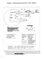
Diagram 1: Wiring Diagram 542 20 30-79, 1.5HP, 115V/60/1
NOTE: Motors used on this unit are manufactured by Baldor Electric Company. For any motor servicing or warranty
work, the motor must be taken to a Baldor Authorized Service Center. The Service Center nearest you can be
found on the Internet under www.balder.com/support/. If access to the Internet is not available, contact us at
the Customer Service listed on teh back cover of this manual.
18
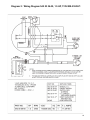
Diagram 2: Wiring Diagram 542 00 06-05, 1.5 HP, 115V/208-230/60/1
19
NOTES:
NOTAS:
REMARQUE :
20
Corporate Office
17400 West 119th Street
Olathe, Kansas 66061 USA
Customer Service: 800-288-5040
Customer Serv. Fax: 800-825-0028
Corporate Office: 913-928-1000
Corp. Office Fax: 913-438-7951
International
Customer Service: 913-928-1300
Customer Serv. Fax: 913-438-7938
www.husqvarna.com
Please record the Date of Purchase and the Serial Number, the Model Number of the equipment and the Date
of Purchase of your equipment in the space below. When ordering service items, please have this information
available.
Serial Number:
Model Number:
Date of Purchase:.
.
Where Purchased:
NOTE: Motors used on this unit are manufactured by Baldor Electric Company. For any motor servicing or warranty
work, the motor must be taken to a Baldor Authorized Service Center. The Service Center nearest you can
be found on the Internet under www.balder.com/support/. If access to the Internet is not available, contact
us at the Customer Service listed on teh back cover of this manual.
21
22