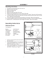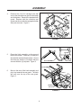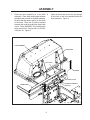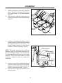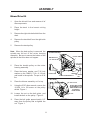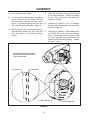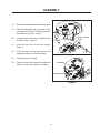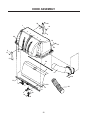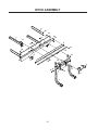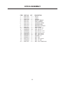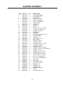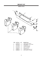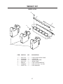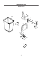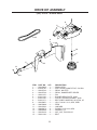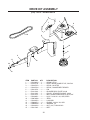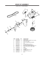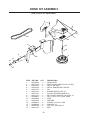
1
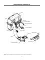
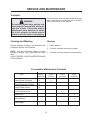
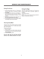
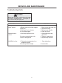
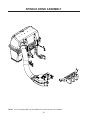
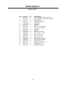
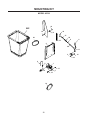
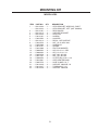
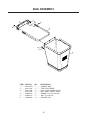
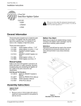
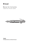
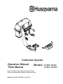
Collection System
Operators Manual
Parts Manual
Models: 111280 / HCS9
Please read these instructions carefully and make
sure you understand them before using the machine.
MANUAL NO. 539111288 REV 01 (03/31/05)
111281 / HCS13
©2005 Husqvarna. All Rights Reserved.
Beatrice, NE. Printed in U.S.A.
2
INDEX
Operators Guide
Features and Controls .............................................................. 4
General Information ................................................................. 5
Safety Procedures .................................................................... 5
Unpacking Instructions ............................................................. 7
Assembly Instructions .............................................................. 7
Collection System .............................................................. 7
Blower/Drive Kit ............................................................... 11
Operating the Collection System ........................................ 14
Maintenance and Service Instructions
Transport ................................................................................ 15
Cleaning and Washing ........................................................... 15
Storage ................................................................................... 15
Preventative Maintenance Schedule ...................................... 15
Caring for Vacuum Hoses ...................................................... 16
Cleaning Poly Mesh ............................................................... 16
Caring for Bags ...................................................................... 16
Troubleshooting Guide ........................................................... 17
Replacement Parts
Hood Assembly ...................................................................... 20
Hitch Assembly ....................................................................... 22
Blower Assembly .................................................................... 24
Weight Kit (Model HCS13) ..................................................... 26
Weight Kit (Model HCS9) ....................................................... 27
Mounting Kit (Model HCS13) ................................................. 28
Mounting Kit (Model HCS9) ................................................... 30
Bag Assembly ........................................................................ 32
Drive Kit (42” Deck) ................................................................ 33
Drive Kit (48” Deck) ................................................................ 34
Drive Kit (52” Deck) ................................................................ 35
Drive Kit (61” Deck) ................................................................ 36
WARNING: Engine exhaust, some of its constituents, and certain vehicle components contain or emit chemicals known to the State of California to cause cancer and birth defects or
other reproductive harm.
3
FEATURES & CONTROLS
HOOD
INLET
LATCH
SUPPORT LINKAGE
SUPPORT BRACKET
HITCH
HITCH BRACKET
REAR GUARD
BAG
WEIGHT BAR
DRIVE KIT
HOSE
CAST WEIGHT
BLOWER ASSEMBLY
NOTE: Your Front Weight Bar may look different from those shown in this diagram.
4
SAFETY RULES
Safety Procedures
General Information
This manual will assist you in the safe operation
and proper maintenance of your Husqvarna
equipment. Read it thoroughly before attempting
to operate the machine. Call your dealer or
Husqvarna if additional information is required.
1 - Training:
• Read the Operator’s manual. If the operator(s)
or mechanic(s) can not read English it is the
owner’s responsibility to explain this material to
them.
• Become familiar with the safe operation of the
equipment, operator’s controls, and safety
signs.
• All operators and mechanics should be trained.
The owner is responsible for training the users.
• Never let children or untrained people operate
or service the equipment. Local regulations may
restrict the age of the operator.
• The owner/user can prevent and is responsible
for accidents or injuries occurring to themselves,
other people, and/or property.
The following safety symbols are used throughout
the manual to alert you to information about unsafe
actions or situations:
DANGER indicates immediate hazards that
may result in severe injury or death.
WARNING indicates unsafe actions or
situations that may cause severe injury,
death, and/or major equipment or property
damage.
2 - Preparation:
• Wear appropriate clothing including hard hat,
safety glasses and ear protection. Long hair,
loose clothing or jewelry may get tangled in
moving parts.
• Inspect the area where the equipment is to be
used and remove all objects such as rocks, toys
and wire which can be thrown by the machine.
• Use extra care when handling gasoline and
other fuels. They are flammable and vapors
are explosive. Use only an approved container.
Never remove gas cap or add fuel with engine
running. Allow engine to cool before refueling.
Do not smoke while fueling or operating
equipment. Never refuel or drain the machine
indoors.
• Check that operator’s controls, safety switches,
hoses, and shields are securely attached and
functioning properly. Do not operate unless
they are functioning properly.
CAUTION indicates unsafe actions or
situations that may cause injury and/or
minor equipment or property damage.
This equipment should not be modified without the
manufacturer’s prior written authorization. Doing
so may not only affect the equipments’
performance and durability, but also create safety
hazards for the operator and the surroundings.
Warranty will be void if changes are made to the
equipment without the manufacturer’s prior written
authorization.
5
SAFETY RULES
3 - Operation
• Never run an engine in an enclosed area.
• Only operate in good light, keeping away from
holes and hidden hazards.
• Slow down and use extra care on hillsides.
Make turns gradually and at slow speed. Do
not operate across the sides of slopes. Operate
up and down slopes only. Do not operate on
steep slopes.
• Turf conditions can affect the machine’s stability.
Do not operate on wet grass where traction may
be reduced.
• Do not change the engine governor setting or
overspeed the engine.
• Stop equipment and inspect vacuum impeller
and hoses after striking objects or if an abnormal
vibration occurs. Make necessary repairs before
resuming operations.
• Look behind and down before backing up to
ensure a clear path.
• Slow down and use caution when making turns
and crossing roads and sidewalks. Stop vacuum
and mower blades if not mowing.
• Do not operate machine under the influence of
alcohol or drugs.
• Use care when loading or unloading the machine
into a trailer or truck.
• Use care when approaching blind corners,
shrubs, trees, or other objects that may obscure
vision.
4 - Maintenance and Storage:
• Stop engine and disconnect spark plug wire.
Wait for all movement to stop before adjusting,
cleaning, or repairing.
• Clean grass and debris from muffler and engine
to help prevent fires. Clean up oil or fuel
spillage.
• Let engine cool before storing and do not store
near sparks or open flame.
• Shut off fuel while storing. Do not store fuel
near flames or drain indoors.
• Never allow untrained personnel to service
machine.
• Keep hands and feet away from moving parts.
If possible, do not make adjustments with the
engine running.
• Keep all parts in good working condition and all
hardware tightened. Replace all worn or
damaged decals.
6
ASSEMBLY
Unpacking Instructions
1.
2.
3.
4.
5.
6.
7.
8.
Cut plastic tie securing the hitch to the crate top.
Remove the top of the crate.
Remove the plastic bag.
Remove the hose.
Remove the sides and ends of the crate.
Remove the mounting kit box from the corner of the crate.
Cut the two plastic ties that secure the hitch assembly to the pallet. Remove the hitch assembly.
Cut the two plastic ties that secure the back of the hood, and the two that secure the front of the
hood. Remove the hood assembly.
9. Cut and two plastic ties that secure the weight bar to the pallet. Remove the weight bar.
10. Cut the two plastic ties that secure the blower assembly to the pallet. Remove the blower assembly.
11. Remove the 1 x 4 that secures the cast weights to the pallet. Remove the weights.
SUPPORT BRACKET
Assembly Instructions
Collection System
Tools Required:
Ratchet
Torque Wrench
1/2" Wrench
1/2" Socket
9/16" Wrench
9/16" Socket
5/8" Socket
(2) 3/4" Wrench
3/4" Socket
Flat Screw Driver
5/32" Allen Wrench
Hacksaw
11/32" Drill Bit
Drill
HITCH BRACKET
LZ MODLES
1.
2.
3.
Open the mounting kit box and remove all of
the components.
Place the support bracket on the frame and
secure with (2) 990563, 3/8 x 1 bolts and (2)
976979, 3/8 nyloc nuts. Figure 1.
Place the hitch brackets on the frame and
secure with (3) 990622, 1/2 x 1 1/4 bolts and
(3) 101331, 1/2 nyloc nuts. Figure 1.
SUPPORT BRACKET
HITCH BRACKET
iZ MODLES
FIGURE 1
7
ASSEMBLY
4.
REAR GUARD
Remove the (10) 5/16 carriage bolts that
secure the standard rear guard to the straps
and skid plates. Remove the standard rear
guard. Replace with the collection rear
guard, and secure with the carriage bolts that
were just removed. Figure 2.
STRAP
FIGURE 2
LANYARD
5.
Place the hitch assembly on the ground
behind the mower. Place the (2) hitch pins
thru the hitch and the hitch brackets. Secure
the hitch pins with the (2) hairpins that are
secured with the (2) lanyards. Figure 3.
HITCH ASSEMBLY
HITCH PIN
HITCH ASSEMBLY
6.
Move to the rear of the hitch assembly and
pick it up towards the rear guard. The latch
will hook over the top of the rear guard.
Figure 3.
LATCH
LANYARD
HITCH PIN
FIGURE 3
8
ASSEMBLY
7.
Place the hood assembly on to the hitch 8.
assembly. Place both hood hinges between
the upper hitch mounts on the hitch assembly.
Be sure that the rubber seal is on the inside
of the hood. Place the (2) friction washers
between the hood hinge and the upper hitch
mount. Place (2)990563, 3/8 x 1 bolt thru the
hinge and mount. Secure with (2) 976979,
3/8 nyloc nut. Figure 4.
Open the hood and secure the (2) springs
to the bolts on the hood assembly and the
hitch assembly. Figure 4.
HOOD ASSEMBLY
HOOD HINGE
3/8 X 1 BOLT
SPRING
3/8 NYLOC NUT
UPPER HITCH MOUNT
RUBBER SEAL
HITCH PIN
FIGURE 4
9
ASSEMBLY
HOOD ASSEMBLY
9.
10.
With the hood open, secure the (3) bags in
place. The back of the bags will hook over
the mounting tabs on the hitch assembly.
Figure 5.
Close the hood, and latch the draw latch over
the draw latch keeper on the hitch assembly.
Figure 5.
DRAW
LATCH
MOUNT
TABS
DRAW LATCH
KEEPER
BAG
FIGURE 5
11.
Install the (2) linkage assemblies to the (2)
support brackets on hitch assembly and the
(2) support brackets on the frame. The
shorter linkage connects to the support
bracket on the hitch assembly. Figure 6.
SUPPORT BRACKET
NOTE: The linkage assemblies may need to be
adjusted. Using (2) 3/4" wrenches, loosen the 1/2"
jam nut on the longer linkage. Turn the turnbuckle
in the appropriate direction to shorten the linkage
assembly. Turn until the slop is taken out of the
linkages. Tighten the jam nut against the
turnbuckle.
TURNBUCKLE
LINKAGE ASSEMBLY
LANYARD
SUPPORT BRACKET
12.
13.
Secure the front of the linkage assemblies
using the hairpin secured by the lanyard.
Secure the rear of the linkages using the (2)
990654, cotter pins provided. Figure 6.
Place the hose on the inlet and secure with
the hose clamp.
FIGURE 6
10
ASSEMBLY
Blower/Drive Kit
1.
Open the drive kit box and remove all of
the components.
2.
Place the deck in the lowest cutting
height.
3.
Remove the right side belt shield from the
deck.
4.
Remove the deck belt from the right side
pulley.
5.
Remove the deck pulley.
Note: When the deck pulley is removed, the
spindle can fall out of the cutter housing
assembly. Be sure to secure the bottom of the
spindle so that this does not happen.
BLOWER ASSEMBLY
PULLEY SHIELD
WELDED STUD
3/8” NYLOC NUT
6.
Place the double pulley on the cutter
housing assembly.
7.
Place the heavy washer, and 7/16 lock
washer on the 108951, 7/16 x 2 1/2 bolt
and install in the spindle. Torque to 45 ft/
lbs.
8.
1/4” FLAT
WASHER
DECK PLATE
PIN
LANYARD
1/4” NYLOC
1/4 X 3/4 CARRIAGE BOLT
NUT
BELT GUIDE
Place the blower assembly on it’s top.
3/8” NYLOC NUT
9.
Using the 5/32" allen wrench, remove the
111229, 1/4 x 5/8 screw on the pulley
shield. Figure 1.
10.
Loosen the nut on the belt guide, and
install the belt on the pulley. Figure 2.
11.
Place the belt guide approximately 1/8"
away from the pulley and re-tighten the
nut. Figure 1.
11
ADJUST BELT GUIDE
APPROXIMATELY 1/8”
AWAY FROM PULLEY
AFTER BELT
INSTALLATION
PULLEY
FIGURE 1
ASSEMBLY
12.
Re-install the pulley shield.
13.
Cut the blower housing along the dashed
line to fit the 52" and 61" decks. Drill the
two small holes indicated with the 11/32"
drill bit. The blower housing will fit 42" and
48" units with no modifications. Figure 2.
14.
Remove the (4) 1/4 x 3/4 carriage bolts from
the deck plate, and the (4) 3/8" nyloc nuts
from the inside of the blower housing.
Figure 1.
15.
Place the deck plate on the welded studs
in the blower housing. Install and tighten
the (4) 3/8" nyloc nuts that were just
removed. Figure 1.
16.
Install the (4) 990074, 1/4 x 3/4 carriage
bolts thru the square holes in the deck plate
from the inside out.
17.
Place the (4) 990598, 1/4 flat washers and
(4) 108120, 1/4" nyloc nuts on the carriage
bolts. The lanyard must be placed on the
top front carriage bolt between the flat
washer and the blower housing. Tighten
the nuts. Figure 1.
CUT ALONG DASHED LINES PER DECK
SIZE AND DRILL CORRECT HOLES TO
11/32” PER DECK SIZE.
61” DECK HOLE
52” DECK HOLE
61” DECK TRIM LINE
FIGURE 2
12
52” DECK TRIM LINE
ASSEMBLY
18.
Remove the discharge chute from the deck.
19.
Place the deck plate pin in the tube on the
back edge of the deck. Rotate the blower
around and into place. Figure 3.
20.
Install the pin thru the tabs on both the deck
and the blower. Figure 3.
21.
Latch the idler arm in the idler keeper.
Figure 3.
22.
Install the belt on the deck pulley and
release the idler arm from the keeper.
23.
Install the new belt shield.
24.
Place the hose on the blower housing and
secure with the over center hose clamp.
DECK PLATE PIN
TUBE
ROTATE
IDLER ARM
IDLER KEEPER
FIGURE 3
13
OPERATION
Operating the Collection System
1.
NEVER USE THE COLLECTION SYSTEM
WITHOUT THE BLOWER ASSEMBLY
AND HOSES SECURELY ATTACHED.
2.
Make sure hoses are connected at both
ends. Inspect hoses prior to each use.
3.
Do not use the unit on slopes greater than
10 degrees.
4.
The mower must be running in order to
vacuum debris through the mower deck.
5.
In heavy grass it may be necessary to mow
and collect at a slower ground speed.
6.
Never attempt to unclog the collection system until the mower’s engine engine has
been shut off and all moving parts have come
to a complete stop.
7.
Do not stand behind the vent at the rear of
the collection system due to the potential for
small pieces of blowing debris to escape
through the vent.
8.
Wear eye and ear protection.
14
SERVICE AND MAINTENANCE
Transport
For best results, clean poly mesh inside hood regularly. Instructions for doing this can be found in
the Service section of this manual.
WARNING
The collection system bags must be completely empty or removed while driving forward onto a trailer. If the mower must be
loaded onto a trailer while there is still debris in the container, the mower must be
backed up onto the trailer to avoid tipping.
Cleaning and Washing
Storage
Regular cleaning, washing, and lubricating will
prolong the service of the machine.
1. Clean machine.
NOTE: Use care with power washers to avoid
damage to decals. Limit direct spray on these
items.
DO NOT EXCEED 1000 PSI WATER PRESSURE
FOR CLEANING.
2. Cover all scratches with touch-up paint.
3. Covered or indoor storage is recommended.
Preventative Maintenance Schedule
Item
Before
Each Use
Inspect/Clean Poly Mesh
X
Check/Tighten Nuts & Bolts
X
Check/Tighten Hoses
X
Every
5 Hours
Every
25 Hours
Every
50 Hours
X
Turn Hose End to End
X
Rotate Hose
X
Clean Machine
X
Inspect Bags
X
15
SERVICE AND MAINTENANCE
Caring For Hoses
Caring For Bags
1. Inspect hoses before each use. If hoses have
excessive wear, tears, or punctures, replace
immediately.
2. To prolong the life of the hose, periodically rotate hose and turn hose end to end. Refer to
Preventative Maintenance Schedule in this
manual.
3. Avoid twists and sharp turns in the hoses, as
they will increase wear on the hoses.
4. Avoid dragging the lower hose along the sides
of buildings or other hard surfaces.
Inspect the bags before each use. If bags have
excessive wear, tears or punctures, replace immediately.
Cleaning Instructions
NOTE: Under normal usage the bag material is
subject to deterioration and wear.
Cleaning Poly Mesh
The poly mesh on the collection system is located
inside the container hood. For best results, clean
poly mesh regularly.
Cleaning Instructions
1. Shut off engine.
2. Release the two (2) rubber latches under the
rear of the hood. Open hood and brush debris
off of both sides.
3. Close hood and re-latch.
DO NOT USE THE COLLECTION SYSTEM
WITHOUT POLY MESH SECURELY IN PLACE.
16
SERVICE AND MAINTENANCE
Troubleshooting Guide
DANGER
Before servicing unit, wait for all moving parts
to come to a complete stop. Turn engine off
and remove the spark plug wire.
PROBLEM
POSSIBLE CAUSE
CORRECTION
Loss of Vacuum.
1. Blower, hose or hood inlet clogged.
2. Bags full.
3. Fan blades bent or broken.
4. Poly mesh plugged.
1. Remove hose and clean inlet.
2. Inspect and empty.
3. Replace/repair impeller.
4. Clean poly mesh.
Unusual vibration
or noise.
1. Solid object jammed in unit.
1. Check and remove any
obstruction.
2. Tighten or replace bolts.
3. Replace/repair impleller.
2. Loose or missing bolts on unit.
3. Bent or damaged fan.
Unit difficult to close.
1. Obstructions keeping door from
completely closing.
2. Hood hinge bolts too tight.
17
1. Clear obstructions.
2. Loosen bolts.
SPINDLE DRIVE ASSEMBLY
NOTE: Your Front Weight Bar may look different from those shown in this diagram.
18
PARTS ILLUSTRATIONS
19
HOOD ASSEMBLY
14
18
1
14
15
4
24
19
13
23
5
17
23
23
5
22
9
6
16
23
7
20
20
11
3
10
10
12
2
8
20
21
19
HOOD ASSEMBLY
ITEM PART NO. QTY
DESCRIPTION
1 ......... 539111172 ....... 1 .......... HOOD
2 ......... 539111174 ....... 1 .......... HOOD SUPPORT
3 ......... 539111175 ....... 2 .......... SUPPORT, DRAW LATCH
4 ......... 539111177 ....... 2 .......... HOOD HINGE
5 ......... 539111181 ....... 2 .......... MOUNT PLATE
6 ......... 539111182 ....... 1 .......... INLET TUBE
7 ......... 539111260 ....... 1 .......... DECAL, VENTILATION
8 ......... 539200478 ...... 2 .......... DRAW LATCH, FLEXIBLE T-HANDLE
9 ......... 539111183 ....... 1 .......... MESH, POLY DIAMOND
10 ....... 539111186 ....... 6 .......... SCREW, #10-24 X 1 1/8, MACH.
11 ....... 539105408 ...... 21 ........ WASHER, #10
12 ....... 539976977 ...... 6 .......... NUT, #10-24, NYLOC
13 ....... 539976978 ...... 8 .......... NUT, 1/4C, NYLOC
14 ....... 539976979 ...... 8 .......... NUT, 3/8C, NYLOC
15 ....... 539990613 ...... 2 .......... NUT, 3/8C
16 ....... 539991003 ...... 8 .......... HCS, 1/4-20 X 1 3/4
17 ....... 539990645 ...... 6 .......... RHSNB, 3/8-16 X 1
18 ....... 539990730 ...... 2 .......... HCS, 3/8-16 X 1 3/4
19 ....... 539990598 ...... 16 ........ WASHER, 1/4
20 ....... 539102744 ...... 11 ........ RIVET, 3/16 X 1/4
21 ....... 539111287 ....... 1 .......... HOSE, 58”, MODEL HCS13
........... 539111314 ....... 1 .......... HOSE, 54”, MODEL HCS9
22 ....... 539111339 ....... 1 .......... HOOD SUPPORT, REAR
23 ....... 539200684 ...... 30 ........ RIVET, 1/4 STAVEX
24 ....... 539110033 ....... 8 .......... WASHER, #10
21
HITCH ASSEMBLY
6
20
10
16
19
11
7
11
5
15
14
15
9
15
8
4
11
13
15
2
18
17
11
12
15
3
1
22
HITCH ASSEMBLY
ITEM PART NO. QTY
DESCRIPTION
1 ......... 539111155 ....... 1 .......... HITCH
2 ......... 539111190 ....... 1 .......... LATCH
3 ......... 539977250 ...... 2 .......... SPRING
4 ......... 539111157 ....... 1 .......... MOUNT Z BRACE
5 ......... 539111167 ....... 1 .......... SEAL, RUBBER
6 ......... 539111158 ....... 2 .......... SUPPORT, OUTER
7 ......... 539111162 ....... 2 .......... SUPPORT ARM
8 ......... 539111267 ....... 2 .......... BRACKET, SUPPORT
9 ......... 539111171 ....... 1 .......... SEAL STRAP
10 ....... 539990580 ...... 3 .......... HCS, 1/4-20 X 3/4
11 ....... 539990563 ...... 20 ........ HCS, 3/8-16 X 1
12 ....... 539990655 ...... 2 .......... HCS, 3/8-16 X 1 1/2
13 ....... 539108369 ...... 2 .......... HCS, 1/2-13 X 1 1/4
14 ....... 539976978 ...... 3 .......... NUT, 1/4C, NYLOC
15 ....... 539976979 ...... 22 ........ NUT, 3/8C, NYLOC
16 ....... 539990254 ...... 4 .......... WASHER, 1/2
17 ....... 539990613 ...... 2 .......... NUT, 3/8C
18 ....... 539101331 ...... 2 .......... NUT, 1/2C, NYLOC
19 ....... 539990625 ...... 4 .......... NUT, 1/2, JAM
20 ....... 539111187 ....... 4 .......... NUT, 1/2-13, WHIZLOCK
23
BLOWER ASSEMBLY
7
LOCKING COLLAR
37
THIS SIDE UP
35
3
15
29
4
20
6
37
30
5
33
26
17
28
2
27
15
3
THIS SIDE DOWN
37
40
22
25
1
11
37
37
19
16
36
38
37
9
14
8
10
13
12
41
40
18
21
31
32
34
33
23
44
39
27
39
HUB DOWN
43
24
42
24
BLOWER ASSEMBLY
ITEM PART NO. QTY
DESCRIPTION
1 ......... 539111225 ....... 1 .......... FLOOR WELDMENT
2 ......... 539111227 ....... 1 .......... BEARING PLATE
3 ......... 539102691 ...... 5 .......... FLANGETTE
4 ......... 539105743 ...... 1 .......... DECAL, NO STEP
5 ......... 539105785 ...... 1 .......... DECAL, WARNING
6 ......... 539106741 ...... 1 .......... DECAL, SERVERING
7 ......... 539102535 ...... 1 .......... GREASE CAP
8 ......... 539916159 ...... 1 .......... SPRING
9 ......... 539111184 ....... 1 .......... BELT GUIDE
10 ....... 539106721 ...... 1 .......... IDLER
11 ....... 539100413 ...... 1 .......... RHSNB, 3/8-16 X 1 1/4, GR5
12 ....... 539200282 ...... 1 .......... NUT, 3/8-16, JAM NYLOC
13 ....... 539990122 ...... 1 .......... WASHER, 3/8, SAE
14 ....... 539111218 ....... 1 .......... IDLER ARM
15 ....... 539106786 ...... 2 .......... BEARING
16 ....... 539102244 ...... 3 .......... BUSHING, MACHINE, 18 GA
17 ....... 539111332 ....... 1 .......... FAN WELDMENT
18 ....... 539106713 ...... 1 .......... SHEAVE, 4”
19 ....... 539102067 ...... 1 .......... KEY, 1/4” SQ. X 3/4”
20 ....... 539111331 ....... 1 .......... FAN COVER
21 ....... 539106504 ...... 1 .......... WASHER, HEAVY
22 ....... 539111228 ....... 1 .......... PULLEY SHIELD
23 ....... 539110813 ....... 1 .......... RETAINER, 1/4C, “U” TYPE
24 ....... 539111220 ....... 1 .......... BLOWER HOUSING
25 ....... 539111265 ....... 1 .......... KEEPER, IDLER
26 ....... 539990074 ...... 6 .......... RHSNB, 1/4-20 X 3/4, GR2
27 ....... 539111229 ....... 3 .......... SCREW, 1/4-20 X 5/8, BTN, SKT HD
28 ....... 539880316 ...... 7 .......... RHSNB, 5/16 X 3/4
29 ....... 539990208 ...... 1 .......... RHSNB, 5/16-18 X 1, GR5
30 ....... 539100472 ...... 3 .......... RHSNB, 5/16C X 1 1/4
31 ....... 539101721 ...... 1 .......... HCS, 5/16-18 X 2 3/4, GR5
32 ....... 539100141 ...... 1 .......... HCS, 7/16-20 X 1 1/2, GR5
33 ....... 539108120 ...... 8 .......... NUT, 1/4C, THIN NYLOC
34 ....... 53999184 ........ 1 .......... NUT, 5/16C, CENTERLOCK
35 ....... 539990196 ...... 3 .......... NUT, 5/16C
36 ....... 539990585 ...... 1 .......... NUT, 5/16C
37 ....... 539990717 ...... 12 ........ NUT, 5/16C, NYLOC
38 ....... 539976979 ...... 4 .......... NUT, 3/8C, NYLOC
39 ....... 539990598 ...... 8 .......... WASHER, 1/4
40 ....... 539990692 ...... 2 .......... WASHER, 5/16
41 ....... 539990517 ...... 1 .......... WASHER, 3/8
42 ....... 539111340 ....... 1 .......... BLOWER SUPPORT
43 ....... 539102744 ...... 6 .......... RIVET
44 ....... 539990247 ...... 1 .......... LOCKWASHER, 7/16
25
WEIGHT KIT
MODEL HCS13
1
2
3
4
6
7
5
9
8
ITEM PART NO. QTY
DESCRIPTION
1 ......... 539020255 ...... 1 .......... WEIGHT BAR, FRONT
2 ......... 539111313 ....... 1 .......... HOLD DOWN, WEIGHT BAR
3 ......... 539102049 ...... 2 .......... CLEVIS PIN
4 ......... 539108096 ...... 2 .......... SPRING RETAINER
5 ......... 539111259 ....... 2 .......... WEIGHT KEEPER
6 ......... 539976979 ...... 4 .......... NUT, 3/8, NYLOC
7 ......... 539990517 ...... 4 .......... WASHER, 3/8
8 ...........539000019........ 3 .......... CAST COUNTERWEIGHT
9 ......... 539976941 ...... 4 .......... HCS, 3/8-16 X 1 1/4, GR5
26
WEIGHT KIT
MODEL HCS9
2
1
7
3
6
4
5
ITEM
PART NO.
QTY
DESCRIPTION
1 ......... 539111313 ....... 1 .......... HOLD DOWN, WEIGHT BAR
2 ......... 539102049 ...... 2 .......... CLEVIS PIN
3 ......... 539108096 ...... 2 .......... SPRING RETAINER
4 ......... 539111337 ....... 1 .......... WEIGHT BAR
5 ......... ER92531 ......... 3 .......... CAST COUNTERWEIGHT
6 ......... 539990627 ...... 4 .......... HCS, 5/16-18 X 1 1/4, GR5
7 ......... 539977778 ...... 1 .......... PAD, ABRASIVE
27
MOUNTING KIT
MODEL HCS13
14
11
REF.
12
16
19
20
9
10
2
4
8
21
3
18
12
14
6
9
1
5
7
13
17
28
15
MOUNTING KIT
MODEL HCS13
ITEM PART NO. QTY
DESCRIPTION
1 ......... 539111322 ....... 1 .......... HITCH BRACKET, RIGHT, W/DECAL
........... 539111199 ....... 1 .......... HITCH BRACKET, LEFT (NOT SHOWN)
2 ......... 539111197 ....... 1 .......... REAR GUARD
3 ......... 539111215 ....... 2 .......... SUPPORT BRACKET
4 ......... 539976989 ...... 2 .......... HAIRPIN #4
5 ......... 539111206 ....... 2 .......... HITCH PIN
6 ......... 539111192 ....... 2 .......... HAIRPIN
7 ......... 539111212 ....... 1 .......... DECAL, HOT SURFACE
8 ......... 539108736 ...... 2 .......... NUT, 1/2-20, HEX JAM
9 ......... 539102563 ...... 4 .......... LANYARD
10 ....... 539111191 ....... 2 .......... SPRING
11 ....... 539102998 ...... 2 .......... FRICTION WASHER
12 ....... 539990563 ...... 6 .......... HCS, 3/8-16 x 1, GR5
13 ....... 539990622 ...... 6 .......... HFS, 1/2-13 X 1 1/2
14 ....... 539976979 ...... 6 .......... NUT, 3/8C, NYLOC
15 ....... 539101331 ...... 6 .......... NUT, 1/2C, NYLOC
16 ....... 539990654 ...... 2 .......... COTTER PIN, 5/32 X 1 1/4
17 ....... 539109901 ...... 1 .......... OVER CENTER BAND
18 ....... 539097076 ...... 1 .......... HOSE CLAMP 6”-& 7”
19 ....... 539111208 ....... 2 .......... SUPPORT LINKAGE, LH
20 ....... 539111207 ....... 2 .......... TURNBUCKLE, 1/2”
21 ....... 539111210 ....... 2 .......... SUPPORT LINKAGE
29
MOUNTING KIT
MODEL HCS9
16
REF.
14
18
13
21
22
20
6
8
12
2
23
11
3
14
16
6
5
1
17
4
7
15
19
30
MOUNTING KIT
MODEL HCS9
ITEM PART NO. QTY
DESCRIPTION
1 ......... 539111294 ....... 1 .......... HITCH BRACKET W/DECALS, RIGHT
........... 539111203 ....... 1 .......... HITCH BRACKET, LEFT (NOT SHOWN)
2 ......... 539111195 ....... 1 .......... REAR GUARD
3 ......... 539111215 ....... 2 .......... SUPPORT BRACKET
4 ......... 539111206 ....... 2 .......... HITCH PIN
5 ......... 539111192 ....... 2 .......... HAIRPIN
6 ......... 539102563 ...... 4 .......... LANYARD
7 ......... 539111212 ....... 1 .......... DECAL, HOT SURFACE
8 ......... 539108736 ...... 2 .......... NUT, 1/2-20, HEX JAM
11 ....... 539976989 ...... 2 .......... HAIRPIN #4
12 ....... 539111191 ....... 2 .......... SPRING
13 ....... 539102998 ...... 2 .......... FRICTION WASHER
14 ....... 539990563 ...... 6 .......... HCS, 3/8-16 x 1, GR5
15 ....... 539990622 ...... 6 .......... HFS, 1/2-13 X 1 1/2
16 ....... 539976979 ...... 6 .......... NUT, 3/8C, NYLOC
17 ....... 539101331 ...... 6 .......... NUT, 1/2C, NYLOC
18 ....... 539990654 ...... 2 .......... COTTER PIN, 5/32 X 1 1/4
19 ....... 539109901 ...... 1 .......... OVER CENTER BAND
20 ....... 539097076 ...... 1 .......... HOSE CLAMP 6”-& 7”
21 ....... 539111208 ....... 2 .......... SUPPORT LINKAGE, LH
22 ....... 539111207 ....... 2 .......... TURNBUCKLE, 1/2”
23 ....... 539111209 ....... 2 .......... SUPPORT LINKAGE
31
BAG ASSEMBLY
1
5
4
4
2
6
5
3
ITEM PART NO. QTY
DESCRIPTION
1 ......... 539110063 ....... 1 .......... HANGER, BAG
2 ......... 539111166 ....... 1 .......... TUBE, BAG FRAME
3 ......... 539111168 ....... 1 .......... BAG, LARGE, MODEL HCS13
........... 539111300 ....... 1 .......... BAG, SMALL, MODEL HCS9
4 ......... 539990316 ...... 7 .......... RHSNB, 5/16-18 X 5/8, GR5
5 ......... 539990717 ...... 7 .......... NUT, 5/16, NYLOC
6 ......... 539990692 ...... 3 .......... WASHER, 5/16
32
DRIVE KIT ASSEMBLY
(539) 111275 - 42 INCH DECK
8
2
4
1
15
6
3
10
9
5
7
12
11
14
13
ITEM PART NO. QTY
DESCRIPTION
1 ......... 539109660 ...... 1 .......... DRAW LATCH
2 ......... 539110740 ....... 2 .......... RIVET, BLIND, DOME STYLE, 5/32 DIA.
3 ......... 539105743 ...... 1 .......... DECAL, NO STEP
4 ......... 539105744 ...... 1 .......... DECAL, DANGER BELT DRIVES
5 ......... 539111270 ....... 1 .......... PIN
6 ......... 539111236 ....... 1 .......... BLOWER DECK PLATE, 42/48
7 ......... 539111255 ....... 1 .......... PULLEY, STACKED DOUBLE, 42/48
8 ......... 539111271 ....... 1 .......... BELT SHIELD W/DECALS & LATCH, 42”
9 ......... 539108951 ...... 1 .......... HCS, 7/16-20 X 2 1/2, GR5, SPEC.
10 ....... 539976998 ...... 1 .......... ZERK
11 ....... 539102563 ...... 1 .......... LANYARD
12 ....... 539990074 ...... 4 .......... RHSNB, 1/4-20 X 3/4, GR2
13 ....... 539990598 ...... 4 .......... WASHER, 1/4
14 ....... 539108120 ...... 4 .......... NUT, 1/4C, THIN NYLOC
15 ....... 539111304 ....... 1 .......... BELT
33
DRIVE KIT ASSEMBLY
(539) 111276 - 48 INCH DECK
2
1
15
3
8
4
6
10
9
5
11
7
12
14
13
ITEM PART NO. QTY
DESCRIPTION
1 ......... 539109660 ...... 1 .......... DRAW LATCH
2 ......... 539110740 ....... 2 .......... RIVET, BLIND, DOME STYLE, 5/32 DIA.
3 ......... 539105743 ...... 1 .......... DECAL, NO STEP
4 ......... 539105744 ...... 1 .......... DECAL, DANGER BELT DRIVES
5 ......... 539111270 ....... 1 .......... PIN
6 ......... 539111236 ....... 1 .......... BLOWER DECK PLATE, 42/48
7 ......... 539111255 ....... 1 .......... PULLEY, STACKED DOUBLE, 42/48
8 ......... 539111272 ....... 1 .......... BELT SHIELD W/DECALS & LATCH, 48”
9 ......... 539108951 ...... 1 .......... HCS, 7/16-20 X 2 1/2, GR5, SPEC.
10 ....... 539976998 ...... 1 .......... ZERK
11 ....... 539102563 ...... 1 .......... LANYARD
12 ....... 539990074 ...... 4 .......... RHSNB, 1/4-20 X 3/4, GR2
13 ....... 539990598 ...... 4 .......... WASHER, 1/4
14 ....... 539108120 ...... 4 .......... NUT, 1/4C, THIN NYLOC
15 ....... 539111305 ....... 1 .......... BELT
34
DRIVE KIT ASSEMBLY
(539) 111277 - 52 INCH DECK
2
3
1
8
15
4
10
6
9
7
5
11
12
14
13
ITEM PART NO. QTY
DESCRIPTION
1 ......... 539109660 ...... 1 .......... DRAW LATCH
2 ......... 539110740 ....... 2 .......... RIVET, BLIND, DOME STYLE, 5/32 DIA.
3 ......... 539105743 ...... 1 .......... DECAL, NO STEP
4 ......... 539105744 ...... 1 .......... DECAL, DANGER BELT DRIVES
5 ......... 539111270 ....... 1 .......... PIN
6 ......... 539111264 ....... 1 .......... BLOWER DECK PLATE, 52
7 ......... 539111256 ....... 1 .......... PULLEY, STACKED DOUBLE, 52
8 ......... 539111273 ....... 1 .......... BELT SHIELD W/DECALS & LATCH, 52
9 ......... 539108951 ...... 1 .......... HCS, 7/16-20 X 2 1/2, GR5, SPEC.
10 ....... 539976998 ...... 1 .......... ZERK
11 ....... 539102563 ...... 1 .......... LANYARD
12 ....... 539990074 ...... 4 .......... RHSNB, 1/4-20 X 3/4, GR2
13 ....... 539990598 ...... 4 .......... WASHER, 1/4
14 ....... 539108120 ...... 4 .......... NUT, 1/4C, THIN NYLOC
15 ....... 539111306 ....... 1 .......... BELT
35
DRIVE KIT ASSEMBLY
(539) 111278 - 61 INCH DECK
2
1
8
15
3
4
6
10
9
5
7
12
11
14
13
ITEM PART NO. QTY
DESCRIPTION
1 ......... 539109660 ...... 1 .......... DRAW LATCH
2 ......... 539110740 ....... 2 .......... RIVET, BLIND, DOME STYLE, 5/32 DIA.
3 ......... 539105743 ...... 1 .......... DECAL, NO STEP
4 ......... 539105744 ...... 1 .......... DECAL, DANGER BELT DRIVES
5 ......... 539111270 ....... 1 .......... PIN
6 ......... 539111240 ....... 1 .......... BLOWER DECK PLATE, 61
7 ......... 539111257 ....... 1 .......... PULLEY, STACKED DOUBLE, 61
8 ......... 539111274 ....... 1 .......... BELT SHIELD W/DECALS & LATCH, 61
9 ......... 539108951 ...... 1 .......... HCS, 7/16-20 X 2 1/2, GR5, SPEC.
10 ....... 539976998 ...... 1 .......... ZERK
11 ....... 539102563 ...... 1 .......... LANYARD
12 ....... 539990074 ...... 4 .......... RHSNB, 1/4-20 X 3/4, GR2
13 ....... 539990598 ...... 4 .......... WASHER, 1/4
14 ....... 539108120 ...... 4 .......... NUT, 1/4C, THIN NYLOC
15 ....... 539111307 ....... 1 .......... BELT
36
37