1
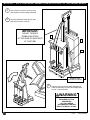
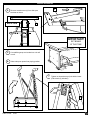
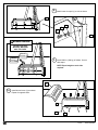
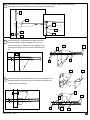
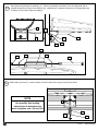
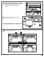
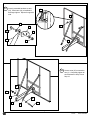
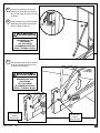
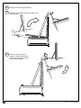
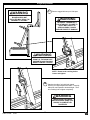
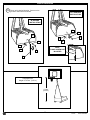
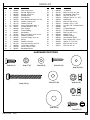
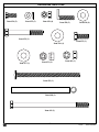
A Huffy Sports Company
Customer Service
N53 W24700 South Corporate Circle
Sussex, WI 53089
U.S.A.
WRITE IN YOUR MODEL NUMBER:
Portable Basketball System
Owners Manual
SAFETY INSTRUCTIONS
FAILURE TO FOLLOW THESE SAFETY INSTRUCTIONS MAY
RESULT IN SERIOUS INJURY,
PROPERTY DAMAGE AND WILL VOID WARRANTY.
NOTICE TO ASSEMBLERS
ALL Huffy Sports basketball Systems, including those
used for DISPLAYS, MUST be assembled and ballasted
with sand or water according to instructions. Failure to
follow instructions could result in SERIOUS INJURY. It is
NOT acceptable to devise a makeshift weight
system.
Owner must ensure that all players know and follow these
rules for safe operation of the unit.
To ensure safety, do not attempt to assemble this system without
following the instructions carefully. Check entire pallet and inside all
packing material for parts. Before beginning assembly, read the
instructions and identify parts using the hardware identifier and parts
list in this document. Proper and complete assembly, use and
supervision are essential for proper operation and to reduce the risk of
accident or injury. A high probability of serious injury exists if this
system is not installed, maintained, and operated properly.
• This equipment is intended for home recreational use only and NOT
excessive competitive play.
• Read and understand the warning label affixed to pole. Label is shown
on page 2.
• The life of your basketball pole depends on many conditions. The
climate, placement of unit, the location of unit, exposure to corrosives
such as pesticides, herbicides or salts are all important.
REQUIRED TOOLS AND
MATERIALS:
• During assembly, if using a ladder use extreme caution. Two people are
recommended for this operation.
• Climate, corrosion and excessive use or misuse could result in pole
failure.
• If technical assistance is required, contact Customer Service Center.
• Adult supervision is recommended when adjusting unit.
• Minimum operational height is 6’ 6” (2 m) to the bottom of backboard.
Most injuries are caused by misuse and/or not following instructions.
Use caution when using this unit.
IMPORTANT!
•
•
•
•
•
•
•
Two People
Carpenters Level
Wrench: 3/4” Or Small Adjustable
Combination Wrenches: (Two) 1/2”, 9/16”
Step Ladder 8 ft. (2.4 m)
Utility Knife
Reversible Drill with 3” Phillips and Standard
Screwdriver Tips
• Ballast (Sand or Dry Cement
480-640 lbs.(218-290 kg))
Have questions?...Don’t go back to the store!
We appreciate your purchasing one of our many fine products. We are sure that you will be very satisfied with your selection. Although
great care and effort have been taken, occasionally problems may occur. To ensure prompt and correct handling of any problems, or to
answer any questions, please contact our Toll-Free Customer Service Number listed below. Service will be quicker if you have your
Model Number (found on carton) and assembly instructions ready when calling. PLEASE WRITE YOUR MODEL NUMBER IN
THE SPACE PROVIDED ABOVE.
Toll-Free Customer Service Number for U.S: 1-800-558-5234 Canada Only: 1-800-284-8339
Internet Address: http://www.hydra-rib.com
printed on recycled paper
1
07/01
P/N 211550A
WARNING
FAILURE TO FOLLOW THESE
WARNINGS MAY RESULT IN SERIOUS
INJURY AND/OR PROPERTY DAMAGE.
Owner must ensure that all players know
and follow these rules for safe operation
of the unit.
· See instruction manual for proper installation
and maintenance.
· Use caution when performing dunk type
activities on this unit.
· Do not hang from any part of unit, including
backboard, support braces, rim or net.
· Do not slide, climb or play on base and/or
pole.
· Surface beneath the base must be smooth
and free of gravel.
· After assembly is complete, distribute ballast
and stake to the ground.
· Never leave unit in an upright position
·
·
·
·
·
·
·
·
·
without placing required amount of ballast in
base, as unit may tip over causing injury.
Keep organic material away from base.
Grass, litter, etc. could cause corrosion
and/or deterioration.
Check pole system for signs of corrosion
(rust, pitting, chipping) and repaint with
exterior enamel paint. If rust has penetrated
through steel anywhere, replace pole
immediately.
Check unit before each use for loose
hardware, excessive wear and signs of
corrosion and repair before using.
Check unit before each use for stability.
Do not use system during windy and/or
severe weather conditions, unit may tip over.
Place system in the storage position and/or
in an area protected from the wind and free
from personal property and/or overhead
power lines.
During play, use extreme caution to keep
player's face away from the backboard, rim
or net.
When adjusting height or moving unit, keep
hands and fingers away from moving parts.
Do not allow children to move or adjust unit.
During play, do not wear jewelry (rings,
watches, necklaces, etc.) Objects may
entangle in net.
In the U.S.: 1-800-558-5234
211411 1/98
P/N 211550A
07/01
2
211411i.eps
1/98
IMPORTANT! WRITE DOWN MODEL NUMBER FROM BOX ON PAGE 1 OF THIS OWNERS MANUAL
1.
2.
Use a fork lift to remove unit from truck
and carefully remove packing materials.
NG
WARNI
Remove backboard, lower pad (1) and
both shroud covers (2 and 3).
IMPORTANT!
BA
CK
DO NOT REMOVE
STABILIZING STRAP
AT THE REAR OF MAIN POST
AT THIS TIME!
3
BO
AR
D
2
1
G
WARNIN
REMOVE AND
DISCARD SCREWS
3.
Remove the three screws which hold base to
pallet and carefully lay unit base forward down
to floor. Discard screws.
WARNING
TWO PERSON MINIMUM
REQUIRED FOR THIS
PROCEDURE.
NOT FOLLOWING
RECOMMENDATION MAY
RESULT IN BODILY INJURY.
HERC01.EPS
211291
AVERTISSEMENT
ADVERTENCIA
3
HERC02.EPS
07/01
P/N 211550A
AVVERTENZA
Ballast Installation
4
Remove extension arm (4) from slide post
brackets as shown.
G
RNIN
E
CL
BACK VIEW
S
ND
HA
EP
KE
AR
4.
4
WA
IMPORTANT!
SET BRAKE
AT THIS TIME.
5.
6.
Cut stabilizing strap and set brake so unit will
not roll.
Raise main post upward into playing position.
HERC04.eps
211291
WARNING
7.
Tighten nut located at top of pole behind mast.
(Flat wrench (5) included.)
KEEP HANDS
CLEAR
5
P/N 211550A
07/01
4
HERC05.
211291
8.
Attach lower front pad (1) to unit as shown.
1
8
7
6
1
WARNING
WARNING
HERC08.EPS
211291
DO NOT USE UNIT
WITHOUT BALLAST
MAY TIP OVER.
AVERTISSEMENT
BALLAST
ADVERTENCIA
BALLAST
BALLAST
80 LB (36 KG)
80 LB (36 KG)
9.
AVVERTENZA
80BALLAST
LB (36 KG)
80 LB (36 KG)
Install 640 lbs. (290 kg) of ballast. Secure
with straps.
NOTE: Equal weight on each side
required.
ATENÇÃO
BALLAST
BALLAST
80BALLAST
LB (36 KG)
80 LB (36 KG)
BALLAST
80
LB (36 KG)
80 LB (36 KG)
WARNING
!WARNUNG
WAARSCHUWING
ADVARSEL
10.
3
HERC09.EPS
211291
Install shroud cover (3) as shown.
Repeat for opposite side.
ADVARSEL
VARNING
BALLAST
WARNNG.EPS
3
9
5
160BALLAST
LB (73 KG)
160 LB (73 KG)
BALLAST
BALLAST
160
LB (73 KG)
160 LB (73 KG)
10
07/01
P/N 211550A
HE
211
11.
Install carriage bolt (39) through rim (11), washers (27) and (36) as shown. Tighten nut (42) completely.
Place nylon lock nut (31) about half-way up carriage bolt (39) as shown.
39
11
31
36
27
42
39
36
12.
Attach bracket (37) to backboard and support structure
by inserting bolts (14) through washers (15) and top
holes in bracket (37), Tighten nuts (16) completely. Peel
and stick foam pad (12) to front of board, behind bracket
(37) .
37
14
15
12
15
16
38
37
13.
Insert inner bracket (38) into bracket (37) as shown. Insert bolts (14)
through washers (15) and top holes of inner bracket (38) as shown,
Tighten nuts (16) completely.
37
14
15
16
P/N 211550A
07/01
6
38
15
14.
Insert spacer (40) through rim assembly (11). Place rim assembly on bracket (37) so the cariage bolt (39) is
inserted through hole on top of inner bracket (38). Install bolt (41), washers (36) and nut (31) through top holes
on bracket (37) as shown.Tighten completely.
BOTTOM VIEW
11
36
40
11
37
39
38
40
31
15.
36
36
41
Install rubber grommet (17), concave washer (18) and center lock nut (19) to bolt (39) as shown.
NOTE
39
Do not over tighten as rim will not
flex properly. See leveling
instructions to determine how
much to tighten nuts (19) and (39).
17
19
7
18
07/01
P/N 211550A
16. RIM LEVELING INSTRUCTIONS:
11
Place level on rim (11) and adjust nut (31) until
level. Tighten nut (42) to set rim tension for
playing.
31
42
17.
20
Install cover plate (20) on rim (11) using self
tapping screws (21) as shown.
20
NOTE ORIENTATION OF COVER PLATE
37
21
18.
Secure net (32) to rim (11).
32
11
1
2
OUTSIDE VIEW
4
3
P/N 211550A
07/01
8
19.
Loosely assemble hardware to strut
(22). Mount strut (22) to backboard
and finger tighten. Repeat for opposite
side.
28
28
15
16
23
24
25
22
26
22
XHRC542A.EPS
211291
20.
Secure struts (22) to extension
arm (4). Completely tighten all
strut hardware in Step 15 and
Step 16.
30
31
22
30
4
22
29
9
07/01
P/N 211550A
21.
22.
Loosen nut located at top of post
behind pole mast (Refer to Steps 6
and 7) and carefully lower pole mast
as shown.
Insert extension arm and backboard
assembly into place and secure as
shown. (Refer to Step 4)
WARNING
TWO PERSON MINIMUM
REQUIRED FOR THIS
PROCEDURE.
NOT FOLLOWING
RECOMMENDATION MAY
RESULT IN BODILY INJURY.
AVERTISSEMENT
ADVERTENCIA
AVVERTENZA
23.
Lift backboard upward at an inclined
angle and position slip pin into slot
as shown for unfolding.
ATENÇÃO
!WARNUNG
WARNING
TWO PERSON MINIMUM
WAARSCHUWING
REQUIRED FOR THIS
PROCEDURE.
AVERTISSEMENT
NOT FOLLOWING
RECOMMENDATION
MAY
ADVARSEL
RESULT IN BODILY INJURY.
ADVERTENCIA
ADVARSEL
AVVERTENZA
VARNING
ATENÇÃO
G
NIN
WAR
G
NIN
WARNNG.EPS
WAR
!WARNUNG
FOR STORAGE:
Position
Slip Pin Here
WAARSCHUWING
P/N 211550A
ADVARSEL
07/01
10
XHRC545a.EPS
211291
TO UNFOLD:
Position
Slip Pin Here
XHRC5405.EPS
211291
Raise pole mast into playing position.
25.
Re-tighten nut located at top of post behind mast.
(Refer to Step 7)
26.
Remove bolt at end of post
brackets. Rotate extension arm
and up into playing position and
re-insert bolt to secure.
WARN
ING
24.
XVAR07.EPS
211492
NG
WARNI
11
07/01
XVAR06.EPS
211492
P/N 211550A
Height Adjustment
27.
WARNING
Remove tagged bolt at top of slide post.
DO NOT UNFOLD UNIT IF
BACKBOARD IS NOT
ELEVATED MAY RESULT IN
DAMAGE TO THE UNIT.
AVERTISSEMENT
WARNING
RE-INSERT TAGGED BOLT
FOR STORAGE! FAILURE TO
DO SO MAY RESULT IN
SERIOUS BODILY INJURY
.
AND/OR PROPERTY
DAMAGE.
7 6
ADVERTENCIA
AVERTISSEMENT
WARN
ING
AVVERTENZA
ADVERTENCIA
ATENÇÃO
AVVERTENZA
!WARNUNG
ATENÇÃO
.
7 0
WAARSCHUWING
!WARNUNG
ADVARSEL
WAARSCHUWING
ADVARSEL
VARNING
WARNNG.EPS
.
7 6
WARNING
DO NOT PLACE HANDS IN
FRONT OF THE MAIN POST.
SUPPORTS IN MOTION MAY
RESULT IN BODILY INJURY.
ADVARSEL
AVERTISSEMENT
ADVERTENCIA ADVARSEL
VARNING
NOTE: Rotate
hand cranking bolt to
AVVERTENZA
loosen and tighten.
HERC13g.EPS
211292
WARNNG.EPS
ATENÇÃO
.
7 0
!WARNUNG
28. Stand to the side of unit with both hands
securely on height adjustment handle. Carefully
slide pole mast upward to desired height. Then
turn cranking bolt to tighten completely.
WAARSCHUWING
ADVARSEL WARNING
WHEN HEIGHT HAS BEEN
ADVARSELADJUSTED
MAKE SURE THAT
AVERTISSEMENT
VARNING
HANDLE IS COMPLETLEY
TIGHTENED.
ADVERTENCIA
WARNNG.EPS
P/N 211550A
07/01
12
AVVERTENZA
Ground Installation
29.
Place unit in desired location. Secure unit to
ground or flat surface as shown.
FLAT SURFACE
INSTALLATION
IN-GROUND
INSTALLATION
33
30
33
35
31
30
30
31
30
NOTE:
FLOOR SCREW NOT
INCLUDED
35
HERC17.EPS
211291
34
HERC16.EPS
211291
Regulation Rim
Height is 10 Feet (3.05 m).
10 feet
(3.05 m)
13
10FT_VAR.EPS
07/01
P/N 211550A
211492
PARTS LIST
Item
Qty.
Part No.
Description
1
2
3
4
5
6
7
8
9
10
11
12
13
14
15
16
17
18
19
20
21
22
1
1
1
1
1
5
5
5
16
16
1
1
1
4
10
6
1
1
1
1
2
2
206597
206592
206593
206574
206556
206572
206143
201114
203415
206151
920263
206591
984001
201611
203218
203100
200484
220043
201124
960043
220140
206567
Pad, Lower Front
Shroud, Right Cover
Shroud, Left Cover
Extension Arm
Flat Wrench
Bolt, Slotted Pan Head, 1/4”-20
Washer, Locking 1/4”
Washer, Flat 1/4”
Screw, Php-Head, #10 x 1”
Fender Washer, 1” O.D.
Rim, Orange
Foam Padding
Backboard
Bolt, Hex Flange, 5/16”-18 x 3”
Washer, Flat 5/16”
Nut, Hex Flange, 5/16”-18
Spring
Washer, Concave
Nut, Hex Locking, 5/16”-18
Cover Plate, Orange
Screw, Tap 1/4” x 3/4”
Backboard Struts
Item
Qty.
Part No.
Description
23
24
25
26
27
28
29
30
31
32
33
34
35
36
37
38
39
40
41
42
2
2
2
4
1
2
1
4
4
1
1
1
1
4*
1
1
1
1
1
1
206585
203153
206116
203001
203474
205220
200514
203335
203063
204282
206557
203124
206252
203032
920262
920038
220065
220064
203439
203017
“L” Bracket
Bolt, Hex 5/16”-18 x 3/4”
Lockwasher, Split, 5/16”
Nut, Hex, 5/16”-18
Washer, Flat 1/2” x 1” O.D.
Weld Studs
Bolt, Hex 3/8”-16 x 3”
Washer, 3/8” x 1” O.D.
Lock Nut, 3/8”-16 Nylon Insert
Net
Tie Down Bracket
Tie Down Stake
Bolt, Hex 3/8”-16 x 1”
Washer, Flat
Bracket, Orange
Inner Bracket, Black
Bolt, Carriage 3/8” x 5 1/2”
Spacer, 5” x 1/2” O.D.
Bolt, Hex 3/8”-16 x 6”
Nut, Hex 3/8”-16
HARDWARE IDENTIFIER
Item #6 (5)
Item #7 (5)
72 slotted pin head, 1/4 x 3/4
206143
Item #8 (5)
Item #9 (16)
203415 Screw #10 x 1
Item #10 (16)
Tooth Washer
206151
Item #15 (10)
Item #14 (4)
Washer 1 O.D.
Item #16 (6)
Item #19 (1)
Item #18 (1)
P/N 211550A
07/01
14
Item #21 (2)
.2187
HARDWARE IDENTIFIER
Item #24 (2)
Item #25 (2)
Item #26 (4)
Item #28 (2)
206116/203305
203153 hex head bolt 5/16 x 3/4
Washer, Lock 9/16 O.D.
5/16 -18
Item #30 (4)
203335
Washer 1 O.D.
203160Weld Stud, rt. angle, 5/16 x 1-1/2
.4375
203001 Hex Head Locknut 5/16
Item #29 (1)
200514 hex head bolt 3/8-16 x 3
Item #35 (1)
Item #36 (4)
Item #27 (1)
Item #31 (4)
Item #42 (1)
Item #39 (1)
Item #40 (1)
Item #41 (1)
15
07/01
P/N 211550A