1
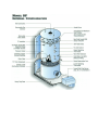
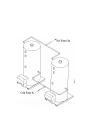
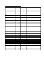
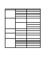
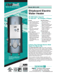
OPERATING AND MAINTENANCE MANUAL FOR
POWER BURNER SERIES FORCED DRAFT
COMMERCIAL WATER HEATER
ELECTRIC HEATER COMPANY
BASE MODEL “ DF ”
HUBBELL ELECTRIC HEATER COMPANY
P.O. BOX 288
STRATFORD, CT 06615
PHONE: (203) 378-2659
FAX:
(203) 378-3593
INTERNET: http://www.hubbellheaters.com/
-- IMPORTANT -Always reference the full model number and serial number when calling the factory.
WARNING / CAUTION
¾ Do not use or store gasoline or any other flammable vapors, liquids, or materials in the
vicinity of this or any other appliance.
¾ Due to the rigors of transportation, all connections should be checked for tightness before heater
is placed in operation.
¾ Safety relief valve must be installed in tapping provided.
¾ KEEP AWAY FROM LIVE ELECTRICAL CIRCUITS.
Do not perform any maintenance, make any adjustments, or replace any components inside the
control panel with the high voltage power supply turned on. Under certain circumstances,
dangerous potentials may exist even when the power supply is off. To avoid casualties, always
turn the power supply safety switch to off, turn the charge or ground the circuit before
performing any maintenance or adjustment procedure.
¾ Installation and service must be performed by a qualified installer, service agency or the gas
supplier. City, state, and national codes governing installation of commercial water heaters
must be followed and take precedence over recommendations in this manual.
¾ The manufacturer’s warranty on this water heater is in effect only when the water heater is
installed and operated in accordance with these instructions and local codes and ordinances or,
in the absence of local codes and ordinances, the National Fuel Gas Code (the latest ANSI
Z223.1). In Canada, installation should conform to the latest CAN/CGAB149 installation
codes and/or local codes. The manufacturer of this water heater will not be held liable for any
damage from failure to comply with these installation and operating instructions.
2
FOR YOUR SAFETY
WHAT TO DO IF YOU SMELL GAS
¾ DO NOT try to light any appliance.
¾ DO NOT touch any electrical switch.
¾ DO NOT use any phone in the building.
¾ Immediately call your gas supplier from a neighbor's phone. Follow the gas supplier's
instructions. If you cannot reach your gas supplier, call the fire department.
¾ WARNING: If these instructions are not followed exactly, a fire or explosion may result
causing property damage, personal injury or death.
PRECAUTIONS
TANK LINING - DAMAGE PREVENTION
The water heater lining has been electronically inspected for continuity prior to final assembly. It was
found to be free of defects. In order to protect the lining, do not apply heavy blows or weld to the
exterior pressure vessel. Damage to the interior lining will void the warranty and ASME HLW stamp.
TANK MAINTENANCE - REMOVAL OF SEDIMENT AND SCALE
To keep the water heater efficient and in good working condition, inspect and clean two weeks after
installation to remove any piping system debris that may have accumulated. Do not acidize this unit.
Monthly inspections should be performed to determine a time span for removing any sediment
within the unit. This should become the basis for a routine maintenance schedule. It is recommended
that high-pressure water be used to purge any accumulation of sediment through the drain valve
opening or the hand hole.
ANODE MAINTENANCE
The water heating industry knows that many water heaters are installed in areas where the water supply
can be abnormally corrosive due to low pH or an excessive amount of dissolved oxygen. Because of
our commitment to provide clear water in all areas, an anode has been provided to help counteract the
effects of these factors. Periodic inspection and, if necessary, replacement is required to assure the
anodes effectiveness.
WATER QUALITY - pH LEVEL
Materials used in the water heater to prevent corrosion have been selected for their compatibility with
most domestic water supplies. However, significantly alkaline water (pH 7.5 or higher) or acidic water
(pH 6.5 or lower) can result in abnormal scale formation or seriously attack these materials and cause
premature corrosion. If the pH of incoming supply water does not fall between 6.5 and 7.5, it must be
treated to prevent damage to internal water heater surfaces and other building plumbing components.
3
SAFETY TEMPERATURE AND PRESSURE RELIEF VALVE (T&P)
A listed and properly rated combination temperature and pressure relief valve shall be installed in the
opening provided and marked for this purpose at the time of installation. Local codes shall govern
installation of relief devices. The pressure rating of the relief valve must not exceed the working
pressure shown on the rating plate affixed to the front of the water heater. The BTU/H rating of the
relief valve must equal or exceed the water heater input shown on the rating plate. The relief valve
discharge line must terminate 6 inches above the floor drain or externally to building. The discharge
line must be able to withstand water temperature in excess of 210°F.
¾ DO NOT install a valve between tank and the relief valve.
¾ DO Install a discharge line directly to an adequate open drain. The discharge line must be
shielded, secured and plumbed to an appropriate drain to prevent scald injury.
¾ DO NOT install a reducing coupling or other restriction in the discharge line.
¾ DO NOT install the discharge line where it may be subject to blocking, plugging or freezing.
¾ DO NOT allow water from discharge line to contact any live electrical part.
Failure to install a listed and properly rated temperature and pressure relief valve could result in
hazard to life, bodily injury or property damage and will release the manufacturer of this water heater
from any claim which might result from excessive water temperature or pressure.
CAUTION
KEEP CLEAR OF DISCHARGE LINE OUTLET. It is hot enough to cause scald injury, is under
pressure and may splash.
IMPORTANT
¾ Periodically check combustion products to assure that carbon monoxide is kept below 0.02%
(200 PPM) or that the CO2 is kept between 9 & 9 ½%.
¾ Drain the water heater for 5 minutes every day to help prevent accumulation of sediment and
scale. Periodically check for the presence of scale and sediment. If present, physically
loosen and flush using high-pressure water.
¾ All startup, periodic tuning and service must be performed by a trained technician familiar
with the water heater and forced draft burner. It is mandatory that the startup test report,
contained in the burner installation and operation manual, be completed and a copy returned
to the factory. It is also important that an operating log be maintained to provide a history of
water heater performance.
4
TABLE OF CONTENTS
SECTION
TITLE
PAGE #
I
GENERAL DESCRIPTION
9
II
INSTALLATION
10
III
START UP AND OPERATION
16
IV
SCHEDULED MAINTENANCE AND SERVICING
18
V
TROUBLESHOOTING
25
VI
MISCELLANEOUS CHARTS AND FORMULAS
26
5
6
8
SECTION I - GENERAL DESCRIPTION
GENERAL DESCRIPTION
This is a commercial storage water heater designed and constructed in accordance with UL and
ASME requirements. Its thermal efficiency and standby loss exceed the levels established by
ASHRAE 90.1 and incorporated by federal EPACT legislation. Given a reasonable amount of
maintenance, this water heating product will perform reliably for many years. Its basic design is well
proven over time, and operating components have been selected for their reliability and widespread
use in the water heating industry. This philosophy also promotes availability of both parts and trained
service personnel. It is essential that all aspects of installation, maintenance, routine servicing,
troubleshooting and repair be planned with safety as the primary consideration. If the installer or
service technician has any questions about this water heater's operation, the factory should be
contacted immediately. It is also very important to properly maintain this water heater to obtain long
life and maintain its high efficiency.
9
SECTION II – INSTALLATION
WARNING / CAUTION
For protection against excessive pressures and temperatures, local codes require the installation of a
temperature-and-pressure (T&P) relief valve certified by a nationally recognized laboratory that
maintains periodic inspection of production of listed equipment of materials, as meeting the
requirements for Relief Valves and Automatic Gas Shutoff for Hot Water Supply Systems. ANSI
Z21.22-1971.
The National Fuel Gas Code, (ANSI Z223.1 and Can 1 -Bl 49.1 or Bl 49.2), expressly prohibits the
following:
1. Installation of water heater in a bathroom, bedroom, or any occupied room normally kept
closed.
2. Installation of a water heater in a garage unless the unit is installed so that the burner and
ignition devices are at least eighteen (18) inches above floor level and protected to avoid
damage by a moving vehicle.
If unit is painted or insulated on the job site, care should be taken not to paint or insulate over the
A.S.M.E. nameplate. This plate should be accessible and legible at all times to inspectors, and
information from this plate must be used when ordering parts from the factory.
HANDLING
Some models have been constructed with lifting lugs to permit lifting with a crane. Fork lift
movement (rear access only) is also acceptable.
To lift with a crane, remove flue outlet adapter and connect a lifting cable to the two lifting lugs
attached to the top tubesheet. Be sure lifting cable and crane can support the shipping weight as
shown on Bill of Lading.
The skids are compatible with the forks of most fork lift equipment. When moving a heater into
place, pick water heater up from rear (do not pick up from front or sides) with forks inside the skids.
Picking up heater on outside of skids may allow forks to puncture bottom of combustion chamber.
INSPECTION
Inspect the water heater and burner for possible damage that may have occurred in shipping or during
storage. Check rating plate on the water heater and burner for compliance with specifications. Be
sure the electrical supply, gas and/or oil supply lines are adequate for the installation.
10
LOCATION
NOTE: Do not run uninsulated water pipes in front of or directly above a fresh air opening. If an
exhaust fan is installed in the mechanical room, the combustion air inlet must allow for the fan's
exhaust air volume. An undersized opening may cause down drafts resulting in poor combustion,
sooting and carbon monoxide.
1. Position the water heater in a clean and dry location as close as possible to the greatest use of
hot water (and the oil storage tank if used). Minimum clearances for servicing are listed on a
label near the burner. Greater clearances may be required by local code.
2. An adequate uncontaminated air supply for combustion is needed. If air is directly obtained
from outdoors, a free area of 1 square foot per 1,000 CF/Hr1 of input is required. If air is
obtained from an adjacent indoor area, 1 square inch per 1,000 BTU/Hr of input is required.
If oil-fired, 1 gallon per hour equals 140,000 BTU/Hr. Combustion air inlets should be
located on an outside wall, away from prevailing winds, and be sized to accommodate all fuel
burning equipment located in the mechanical room. Combustion air calculations should
assume simultaneous operation of all fuel burning equipment in the equipment room.
3. The water heater should not be installed in an area where combustible liquids or vapors may
be present that could be ignited by the burner. The installation area should not contain air
contaminated with chlorinated hydrocarbons, perchlorethylene or any strong oxidizing agent.
Combustion air containing these agents will seriously damage the burner and vessel parts
thus voiding all warranties. If required, combustion air should be ducted from outside the
building to avoid such contaminants. Burners require special construction for outside
combustion air applications. Consult factory for details.
4. The water heater should be located on a pitched floor near a suitable drain, or other
provisions must be made to prevent damage to areas of the building subject to water damage
should the heater or plumbing leak. A drain is required for relief valve discharge as well as
routine cleaning and flushing of the tank. The heater must be installed in a level position.
Shim under skids if necessary.
WATER CONECTIONS
NOTE: The most effective means for preventing deterioration from accelerated corrosion due to
galvanic and stray current is the installation of dielectric fittings/unions. The installation of these
fittings is the responsibility of the installing contractor.
Water connections are made to the cold water inlet and hot water outlet as shown on the supplied
water heater drawing. Dielectric fittings are provided to minimize the formation of galvanic
corrosion (some jurisdictions require the use of dielectric fittings). Shut-off valves and unions should
1
1,000 CF/Hr of Gas = 1,000,000 BTU/Hr = 7.14 GPH of #2 fuel oil
11
be installed so the heater may be disconnected for servicing if necessary. Hot water and return
circulation lines should be insulated. The cold water supply line should be insulated if subjected to
freezing temperatures. When a check valve is installed in the cold water line to the water heater, a
diaphragm type expansion tank suitable for potable water shall be installed in the system.
PIPING MULTIPLE WATER HEATERS
A parallel connection, see the following diagram, allows heated water from multiple heaters to flow
into the system to serve peak loads that can occur in a short time period. Pressure drop is reduced
and total storage capacity is available for immediate use.
12
ELECTRICAL CONNECTIONS
Electrical connections to the water heater should conform to the National Electrical Code or the code
legally authorized in your locality. A fused disconnect switch should be used in the burner control
circuit. The contractor shall run the properly sized electrical service to the terminals indicated on
burner wiring diagram. Refer to burner manufacturer's manual for specific electrical requirements.
VENTING
This non-condensing water heater is designed to exhaust into its own independent vent or into an
existing vent system that serves other appliances. In all cases, a negative pressure must be
maintained within the venting system to prevent the leakage of combustion products.
Several basic venting rules must always be followed.
1. The vent must be independently supported so its weight does not bear on the water heater's
flue collector.
2. The vent must never be sized smaller than the flue collector outlet. It can be up to two sizes
larger but, in all cases, must be sized in accordance with National Fuel Gas Code
Requirements given the particular installations vent configuration and water heater input rate.
3. When a relatively high negative draft occurs in a vent, a draft regulator sized to the vent
diameter should be installed and adjusted to begin opening at a negative draft of -0.1 in.
W.C. A draft regulator should be installed no further than two feet away from the water
heater flue outlet.
4. A vent must never be welded to the flue collector outlet.
5. All vents must be constructed in accordance with the National Fuel Gas Code and terminated
on the outside of the building using a UL listed vent cap. Horizontal venting through an
outside wall is acceptable, but an induction blower may be needed to maintain a negative
draft in the vent.
If the water heater is vented into an existing overhead vent (or breaching), it is recommended the
vent be designed for positive pressure in case there is positive pressure in the overhead vent.
13
GAS CONNECTION PIPING FOR GAS AND COMBINATION GAS/OIL BURNERS
WARNING / CAUTION
LP UNITS; liquefied petroleum (L.P.) gas is heavier than air and will remain at floor level if there is
a leak. Basements, crawl spaces, closets and areas below ground level will serve as pockets for
accumulation of leaking L.P gas. Before operating the water heater, sniff at floor level. IF YOU
SMELL GAS, follow applicable instructions on cover page. DO NOT OPERATE APPLIANCE
UNTIL LEAKAGE IS CORRECTED AND AREA IS PURGED OF ANY GAS
ACCUMULATION.
Be sure gas supply lines have been cleaned of all debris which could enter the regulators or the
burner system and cause malfunctions or unsafe conditions. Pipe connection compounds must be
used AT ALL TIMES. DO NOT use Teflon tape as a thread sealant.
1. The gas supply line must be sized, considering pressure drop, to furnish gas at a pressure
necessary for the burner to develop rated capacity and the CFH to handle all fuel burning
equipment attached to the line. A drip leg should be installed ahead of the burner piping
connection. See burner manufacturer's manual for piping detail.
2. Piping or tubing from regulator vents shall be routed outside the building and must be the
same diameter as the regulator venting ports. Provide no traps in the vent lines and terminate
away from all doors, windows and air intakes serving HVAC equipment. Vent termination
shall face downward with a screen mesh cover to prevent insects and debris from entering. If
regulator vents are combined, use tubing or pipe equal to the total cross sectional area of the
individual vents. Normally open vent valves must be separately vented.
NOTE: High and low gas pressure switches must be vented separately from those of the main and
pilot regulators. Termination of vents shall be the same as for regulators.
3. Before gas is turned on, be sure the gas line has been checked for leaks. Check to see that
there are no open fittings and that the burner main manual valve and pilot manual valve are
closed.
OIL TANK AND PIPING
1. Tank construction and installation must meet all local codes and should meet the
specifications recommended by Underwriters Laboratories.
2. REFER TO YOUR BURNER STARTUP MANUAL FOR OIL PUMPING AND
PIPING DETAILS.
14
3. A Rule of Thumb to determine total suction for suction line sizing is to add 10% to suction
determined from the burner manufacturer's instruction manual.
4. It is good practice to size the oil pump return-line (to the tank) the same size as the selected
suction line.
PRESSURE AND TEMPERATURE SAFETY RELIEF VALVE
1. Install the combination temperature and pressure safety relief valve in the tapping provided.
Note that this is required by law for safety considerations.
Outlet to floor drain
Install into provided tapping
Manual Release
Lever
Temperature Probe
2. Install a relief valve overflow pipe to a nearby floor drain. CAUTION: No valve of any type
should be installed between the relief valve and tank or in the drain line.
15
SECTION III – START UP AND OPERATION
WARNING / CAUTION
Temperatures above 130ºF (54º C) can cause scalding. Scalding temperatures are especially
hazardous to young children, aged or handicapped persons. A serious or disabling injury can occur.
Note that a mixing valve installed at the hot water outlet can reduce the risk of scalding at such
points of use as lavatories, sinks and bathing facilities
Excessively hot water may suggest that the upper operating thermostat has failed. If you determine
an operating control thermostat has failed, it should be replaced IMMEDIATELY by a qualified
service technician.
If the burner turns on and off every 3 to 4 minutes on a regular basis, the lower control thermostat
setting may have to be decreased. Such a "short cycling" condition accelerates wear of burner
components which can lead to early failure.
IMPORTANT
THE MANUFACTURER'S START UP REPORT MUST BE COMPLETED AND
RETURNED. FAILURE TO DO SO WILL VOID THE WARRANTY.
ALWAYS CONTACT A TRAINED SERVICE TECHNICIAN TO PERFORM START UP.
SHOULD FACTORY ASSISTANCE BE REQUIRED, PLEASE HAVE THE WATER
HEATER SERIAL NUMBER AVAILABLE.
Combination gas/oil burners require a supply of oil for oil pump lubrication even when operating on
gas.
Some oil burners require a supply of either natural or L.P gas to operate the pilot. Check burner
construction for the presence of gas pilot tubing and a pilot gas pressure regulator.
START UP
1. Fill water heater and drain to remove any residue that may have accumulated during the
installation process. Remove hand hole cover and remove any material not flushed through
drain. Reinstall hand hole cover, fill with water and open a nearby hot water faucet to bleed out
any entrapped air. Be sure all tank connections are tight. Leaking water causes corrosion and
insulation damage.
16
2. The burner manufacturer's installation and operation manual, included with this manual,
contains a detailed start up procedure that should be studied and followed precisely.
NOTE: Rated gas input for this water heater can be established by adjusting manifold gas pressure
to the value listed on the burner data plate. Rated oil input can be established by adjusting oil
pressure to the burner at 300 psi (pressure may have to be slightly reduced to obtain clean, smokefree combustion).
TEMPERATURE ADJUSTMENT
The upper operating control thermostat shuts off the burner when its temperature setting is reached.
The lower operating control thermostat can be adjusted to vary the temperature that activates the
burner. The unit is also equipped with a high limit safety control preset at 180°F. For energy efficient
operation of your water heater, the recommended upper temperature setting is approximately 130°F.
Facilities with small children or invalids may require a 120°F or lower temperature setting to reduce
the risk of scald injury. Some states require a lower temperature setting. Check with your gas
supplier for local requirements governing the temperature setting.
Remember that no water heating system will provide an exact temperature at all times. Allow a few
days of operation to determine the correct temperature setting consistent with your needs.
A lower temperature setting can cause condensation, but that does not mean your tank is leaking.
Many reported tank leaks on installation are proven to be condensation. To avoid unnecessary
inconvenience and expense, make sure the tank is leaking before calling a service person.
17
SECTION IV - SCHEDULED MAINTENANCE AND SERVICING
WARNING / CAUTION
Before performing any maintenance procedure, turn off the water heater main disconnect switch
before performing any cleaning or service. Also close both the pilot and main manual shutoff valves.
Keep the equipment room clean. Clean the burner at regular intervals. The blower inlet can collect
dust and debris from the air during operation. Clean blower wheel and flame scanner when
necessary. The burner should be cleaned each year according to the burner manufacturer's
recommended procedures. A DIRTY BLOWER WHEEL WILL REDUCE EFFICIENCY AND
MAY CAUSE POOR COMBUSTION, SOOTING OR THE PRODUCTION OF CARBON
MONOXIDE.
IMPORTANT
A preventive maintenance program should be established to help assure a long, trouble-free water
heater life. AN ANNUAL INSPECTION SHOULD BE PERFORMED AND DOCUMENTED.
A COPY OF THE INSPECTION REPORT MUST BE FORWARDED TO THE
MANUFACTURER. FAILURE TO DO SO WILL VOID THE WARRANTY.
18
RECOMMENDED PERIODIC INSPECTION
DAILY
1. Inspect area around water heater for moisture. If present, determine if cause is condensation
or leakage.
a. If cause is condensation - May be due to very cold incoming water. Consider
installation of intra-tank circulator; contact manufacturer for details.
b. If cause is leakage - May be due to leaking fitting; repair as soon as possible. If tank
leak is suspected, contact manufacturer.
2. Inspect vent for corrosion. If present, replace corroded vent section as soon as possible.
Determine if cause is low temperature of combustion products (less than 280º F net flue
temperature), or the presence of contaminated combustion air. Correct either condition
immediately.
MONTHLY
1. Drain heater, remove hand hole cover and inspect for sediment accumulation. Remove any
sediment and inspect more frequently to determine an appropriate schedule for sediment
removal. NOTE: FAILURE OF THE WATER HEATER DUE TO SEDIMENT OR
SCALE ACCUMULATION IS NOT COVERED BY THE WARRANTY.
2. Test combustion products for the presence of carbon monoxide (CO) above a 200 ppm
concentration. If necessary, adjust burner to reduce CO concentration.
19
RECOMMENDED PERIODIC TESTING
TESTING
ITEM
Gauges, monitors and operating log
Instrument and equipment settings
HOW
OFTEN
COMPLETED
BY
REMARKS
Daily
Daily
Operator
Operator
Weekly
Semiannually
Annually
Monthly
Operator
Service Tech
Service Tech
Operator
Igniter
Weekly
Operator
Fuel valves: pilot and main
(primary and secondary)
Weekly
Operator
Pilot and main gas or oil train
Combustion safety controls (flame
failure)
Annually
Weekly
Service Tech
Operator
Flame signal strength
Weekly
Operator
Pilot turndown test
As required /
annually
Service Tech
Low-water fuel cutoff and alarm
Daily/weekly
Semiannually
Annually
Annually
Monthly
Operator
Firing rate
Flue, vent, stack or outlet dampers
High limit safety thermostat control
Operating thermostat control
Vent draft fan, and air pressure
switches
High and low gas pressure interlocks
Monthly
High and low oil pressure interlocks
Monthly
Fuel valve interlock switch
Annually
Low fire start interlock
Annually
Automatic changeover control (dual
At least
fuel)
annually
As required
T&P valves
Inspect Burner Components
20
Semiannually
Service Tech
Service Tech
Operator
Make visual inspection and record readings
Make visual check against recommended
specifications
Verify factory settings
Verify factory settings
Check with combustion test
Make visual inspection of linkage; check for
proper operation
Make visual inspection, check flame signal
strength if meter-fitted (see "Combustion Safety
Controls")
Operate burner. Using a manometer or pressure
gauge, check pressure to the burner as required
on rating label.
Perform leakage tests - refer to instructions
Close manual fuel supply for the pilot and main
fuel valve(s); check safety shutdown timing; log
result.
With flame signal meter installed, read and log
for both pilot and main flames. Notify service
organization if readings are very high, very low
or fluctuating. Refer to instructions for nominal
values
Required after any adjustment to flame scanner
mount or pilot burner; verify annually - refer to
instructions.
Refer to instructions and perform a slow drain
test.
Refer to instructions
Refer to instructions
Refer to instructions
Operator
Operator
Operator
Operator
Service Tech
Refer to instructions
Refer to instructions
Refer to instructions
Refer to instructions
Under supervision of gas utility
Operator
Operator
In accordance with procedure in Section VI
ASME Boiler and Pressure Vessel Code,
Recommended Rules for Care and Operation of
Heating Boilers.
Refer to burner instructions
BURNER SERVICE
IMPORTANT
IT IS HIGHLY RECOMMENDED THAT REPLACEMENT PARTS OR ASSEMBLIES BE
OBTAINED FROM THE WATER HEATER OR BURNER MANUFACTURER.
The enclosed burner installation and operation manual contains a service suggestion
(troubleshooting) section and a periodic checklist that recommends a variety of component tests
designed to help maintain the water heater's reliable, efficient and safe operation.
For additional assistance, contact the burner manufacturer's customer service department.
Availability of spare parts varies from area to area. The burner material list provides the part number
you require for obtaining replacements. If the item is not available locally, contact the service
department at the location listed on the cover page.
WATER HEATER SERVICE
Serviceable water heater components include the control and high limit thermostats, the temperature
and pressure relief valve(s), the drain valve and , low water cut off. Optional components such as a
temperature and pressure gauge may also be installed. Replacement instructions for some of these
items are listed below.
For additional assistance, contact the water heater manufacturer's customer service department.
22
RELIEF VALVE
1. Disconnect power from unit.
2. Shut off incoming water and boiler water supply.
3. Lift test lever on relief valve to relieve pressure in tank.
4. Disconnect overflow piping.
5. Unscrew relief valve, remove assembly and replace with new one.
6. Connect overflow piping.
7. Turn on incoming water supply and check for leaks.
8. Turn safety switch to ON position.
Test Lever
Overflow Piping Outlet
Tank Connection
Temperature Probe
23
IMMERSION TEMPERATURE HIGH LIMIT CUT-OFF, HIGH, OR LOW THERMOSTAT
1. Disconnect power from unit.
2. Remove access cover.
3. Remove high limit cover screw and cover.
Cover
Cover Screw
Reset Tab (High Limit Only)
4. Disconnect the two (2) 14 gauge wires.
Wires
Capillary Tube
5. Remove capillary tube and bulb from
thermowell
6. Remove two (2) mounting screws.
Mounting Screws
7. Remove control and install new high limit switch by performing above steps in
reverse order. (Note: Be sure to place capillary tube into slot in base prior to installing cover.)
24
SECTION V – TROUBLESHOOTING
(See separate component O&M for additional details.)
Symptom
No hot water.
Probable Cause
Flame safeguard locked out.
Manual gas valve closed.
Blown control circuit.
No power.
Water not hot enough.
Gas pressure too high or too
low.
Operating control thermostat
set too low.
Recovery rate too low for
demand.
Water temperature too hot.
Water leaks.
Gas odors.
Operating control thermostat
failed.
Operating control thermostat
set too high.
Temperature and pressure
safety relief valve not closed.
If leakage source cannot be
determined.
Possible gas leak.
Improper combustion.
Blower wheel dirty.
Down draft in vent.
Gas train vents not vented
outdoors.
Blower wheel running
backward.
Corrective Action / Remedy
Reset flame safeguard.
Open gas valve and reset flame
safeguard.
Replace fuse.
Reset circuit breaker.
Reset gas pressure switch and reset
flame safeguard.
Increase control thermostat setting to
a higher temperature. Note: Higher
water temperatures increase the
danger of scalding.
Input rate too low/not operating at
peak efficiency.
Call serviceman to check input rate
and efficiency.
Check firetubes for soot. Inspect and
clean for scale and sediment build-up.
Call serviceman to replace control
thermostat.
Adjust operating control thermostat to
lower temperature.
Replace valve.
Shut off fuel and electrical supply,
close cold water inlet valve, and call
serviceman.
Shut off gas supply and call the gas
company.
Call serviceman.
Call serviceman.
Call serviceman.
Call serviceman.
Call serviceman.
25
SECTION VI – MISCELLANEOUS CHARTS AND FORMULAS
TORQUE VALUES
BOLT SIZE
18-8 S/S
IN.-LBS.
BRASS
IN.-LBS.
4-40
4-48
5-40
5-44
6-32
5.2
6.6
7.7
9.4
9.6
4.3
5.4
6.3
7.7
7.9
26
SILICON
BRONZE
IN.-LBS.
4.8
6.1
7.1
8.7
8.9
ALUMINUM
316 S/S
2024-T4
IN.-LBS.
IN.-LBS.
2.9
5.5
3.6
6.9
4.2
8.1
5.1
9.8
5.3
10.1
MONEL
IN.-LBS.
5.3
6.7
7.8
9.6
9.8
METRIC CONVERSIONS
27