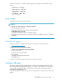
1
HP StorageWorks
XP12000 Disk Array Owner's Guide
Part number: AE002-96039
Twelfth edition: March 2008
Legal and notice information
© Copyright 2004-2005, 2008 Hewlett-Packard Development Company, L.P., all rights reserved.
Confidential computer software. Valid license from HP required for possession, use or copying. Consistent with FAR 12.211
and 12.212, Commercial Computer Software, Computer Software Documentation, and Technical Data for Commercial Items
are licensed to the U.S. Government under vendor's standard commercial license.
The information contained herein is subject to change without notice. The only warranties for HP products and services are set
forth in the express warranty statements accompanying such products and services. Nothing herein should be construed as
constituting an additional warranty. HP shall not be liable for technical or editorial errors or omissions contained herein.
Hitachi and Universal Replicator are registered trademarks of Hitachi, Ltd.
Microsoft and Windows are U.S. registered trademarks of Microsoft Corporation.
Oracle is a registered U.S. trademark of Oracle Corporation, Redwood City, California.
ShadowImage and TrueCopy are registered trademarks of Hitachi, Ltd. and Hitachi Data Systems Corporation.
UNIX is a registered trademark of The Open Group.
Contents
About this guide ................................................................................... 7
Intended audience ...................................................................................................................... 7
Related documentation ................................................................................................................ 7
Document conventions and symbols ............................................................................................... 7
Conventions for storage capacity values ........................................................................................ 8
Rack stability .............................................................................................................................. 9
HP technical support ................................................................................................................... 9
Customer self repair .................................................................................................................... 9
Product warranties .................................................................................................................... 10
Subscription service .................................................................................................................. 10
HP websites ............................................................................................................................. 10
1 Overview of the HP XP12000 Disk Array ............................................ 11
Continuous data availability .......................................................................................................
Nondisruptive service and upgrades ...........................................................................................
Connectivity .............................................................................................................................
Scalability ...............................................................................................................................
Data integrity and high availability .............................................................................................
HP XP12000 product contents ....................................................................................................
Included components ..........................................................................................................
Required additional components ..........................................................................................
Optional components .........................................................................................................
HP XP12000 supported features .................................................................................................
HP XP12000 specifications .................................................................................................
Supported operating systems ...............................................................................................
Supported external storage ..................................................................................................
Web-based array management ............................................................................................
HP StorageWorks XP Continuous Track ..................................................................................
HP XP12000 Software ..............................................................................................................
Storage management software .............................................................................................
Performance management software ......................................................................................
Data protection and recovery software ..................................................................................
Mainframe software ...........................................................................................................
11
11
12
12
12
13
13
13
13
13
14
15
15
16
16
16
16
17
17
17
2 HP XP12000 hardware components ................................................... 19
Hardware overview ...................................................................................................................
Disk control frame .....................................................................................................................
Control panel ....................................................................................................................
Unit emergency power off switch ..........................................................................................
Service processor (SVP) .......................................................................................................
Disk drives ........................................................................................................................
Disk array frames ......................................................................................................................
Disk drives ........................................................................................................................
Backup batteries .......................................................................................................................
XP12000 Disk Array Owner's Guide
19
20
20
24
24
24
24
25
25
3
Optional management server ..................................................................................................... 26
3 HP XP12000 operations ................................................................... 27
General safety guidelines ..........................................................................................................
Powering down the disk array ....................................................................................................
Planned power off ..............................................................................................................
Emergency power off ..........................................................................................................
To power off the disk array in an emergency: ..................................................................
Recovering from an unplanned power outage ...............................................................................
Manual restart after power is restored ...................................................................................
To restart the disk array manually: ..................................................................................
Automatic restart when power is restored ...............................................................................
Operating specifications ............................................................................................................
Temperature ......................................................................................................................
Humidity ...........................................................................................................................
Mechanical vibration ..........................................................................................................
AC line voltage requirements ...............................................................................................
27
28
29
29
29
30
30
30
31
32
32
32
32
33
4 HP XP12000 Troubleshooting ............................................................ 35
Service information messages ..................................................................................................... 35
Failure detection and reporting process ....................................................................................... 35
5 Regulatory statements ....................................................................... 37
FCC EMC statement (USA) .........................................................................................................
IEC statement (worldwide) ..........................................................................................................
EMC statement (Canada) ...........................................................................................................
Spécification ATI Classe A (France) .............................................................................................
VCCI EMC statement (Japan) .....................................................................................................
BSMI EMC statement (Taiwan) ....................................................................................................
RRL EMC statement (Korea) ........................................................................................................
Harmonics conformance (Japan) .................................................................................................
German noise declaration ..........................................................................................................
Laser safety ..............................................................................................................................
Japan DENAN law cordset caution .............................................................................................
European WEEE statements ........................................................................................................
37
37
37
37
38
38
38
38
38
38
39
39
Glossary ............................................................................................ 47
Index ................................................................................................. 53
4
Figures
1 Fully configured HP XP12000 Disk Array .................................................................. 20
2 Control panel ........................................................................................................ 21
3 Backup power sequence .......................................................................................... 25
4 Optional HP XP Command View Advanced Edition Software configuration ..................... 26
5 Failure detection and reporting process ...................................................................... 35
XP12000 Disk Array Owner's Guide
5
Tables
1 Document conventions ............................................................................................... 7
2 HP XP12000 Disk Array specifications ...................................................................... 14
3 Control panel functions ............................................................................................ 21
4 Temperature specifications ....................................................................................... 32
5 Humidity specifications ............................................................................................ 32
6 50-amp, 50 or 60 Hz single-phase DKC AC voltage specifications ................................ 33
7 30-amp, 50 or 60 Hz, single-phase DKC AC voltage specifications ............................... 33
8 30-amp, 50 or 60 Hz, three-phase DKC AC voltage specifications ................................ 33
9 50-amp, 50 or 60 Hz, single-phase DKU AC voltage specifications ............................... 34
10 30-amp, 50 or 60 Hz, single-phase DKU AC voltage specifications ............................... 34
11 30-amp, 50 or 60 Hz, three-phase DKU AC voltage specifications ................................ 34
12 Failure detection and reporting process ...................................................................... 35
6
About this guide
This guide provides information about owning and operating the HP XP12000 Disk Array.
Unless otherwise noted, the term disk array in this guide refers to the HP StorageWorks XP12000
Disk Array.
Intended audience
This guide is intended for system administrators with knowledge of:
• the host hardware
• the operating system
• RAID technology
Related documentation
The following documents provide related information:
• HP StorageWorks XP12000 Disk Array Site Preparation Guide
• HP StorageWorks XP Remote Web Console user guide for XP12000/XP10000 Disk Arrays and
SVS 200
• HP StorageWorks XP disk array configuration guides for host operating systems
You can find these documents from the Manuals page of the HP Business Support Center website:
http://www.hp.com/support/manuals
In the Storage section, click Disk Storage Systems and then select the XP12000 disk array product
under XP Disk Arrays.
Document conventions and symbols
Table 1 Document conventions
Convention
Element
Blue text: Document conventions and symbols
Cross-reference links and e-mail addresses
Blue, underlined text: http://www.hp.com
Website addresses
• Keys that are pressed
Bold text
• Text typed into a GUI element, such as a
box
• GUI elements that are clicked or selected,
such as menu and list items, buttons, tabs,
and check boxes
XP12000 Disk Array Owner's Guide
7
Convention
Element
Italic text
Text emphasis
• File and directory names
• System output
Monospace text
• Code
• Commands, their arguments, and
argument values
Monospace, italic
Monospace, bold
text
text
• Code variables
• Command variables
Emphasized monospace text
WARNING!
Indicates that failure to follow directions could result in bodily harm or death.
CAUTION:
Indicates that failure to follow directions could result in damage to equipment or data.
IMPORTANT:
Provides clarifying information or specific instructions.
NOTE:
Provides additional information.
TIP:
Provides helpful hints and shortcuts.
Conventions for storage capacity values
Use the following values to calculate physical storage capacity (hard disk drives) for HP XP storage
systems:
• 1 KB (kilobyte) = 1,000 bytes
• 1 MB (megabyte) = 1,0002 bytes
• 1 GB (gigabyte) = 1,0003 bytes
• 1 TB (terabyte) = 1,0004 bytes
8
About this guide
Use the following values to calculate logical storage capacity (logical devices) for HP XP storage
systems:
• 1 KB (kilobyte) = 1,024 bytes
• 1 MB (megabyte) = 1,0242 bytes
• 1 GB (gigabyte) = 1,0243 bytes
• 1 TB (terabyte) = 1,0244 bytes
• 1 block = 512 bytes
Rack stability
Rack stability protects personnel and equipment.
WARNING!
To reduce the risk of personal injury or damage to equipment:
•
•
•
•
•
Extend leveling jacks to the floor.
Ensure that the full weight of the rack rests on the leveling jacks.
Install stabilizing feet on the rack.
In multiple-rack installations, fasten racks together securely.
Extend only one rack component at a time. Racks can become unstable if more than one component
is extended.
HP technical support
Telephone numbers for worldwide technical support are listed on the HP support website:
http://www.hp.com/support/
Collect the following information before calling:
•
•
•
•
•
•
Technical support registration number (if applicable)
Product serial numbers
Product model names and numbers
Error messages
Operating system type and revision level
Detailed questions
For continuous quality improvement, calls may be recorded or monitored.
Customer self repair
HP customer self repair (CSR) programs allow you to repair your StorageWorks product. If a CSR
part needs replacing, HP ships the part directly to you so that you can install it at your convenience.
Some parts do not qualify for CSR. Your HP-authorized service provider will determine whether a
repair can be accomplished by CSR.
For more information about CSR, contact your local service provider. For North America, see the CSR
website:
XP12000 Disk Array Owner's Guide
9
http://www.hp.com/go/selfrepair
This product has no customer replaceable components.
Product warranties
For information about HP StorageWorks product warranties, see the warranty information website:
http://www.hp.com/go/storagewarranty
Subscription service
HP strongly recommends that customers register online using the Subscriber's Choice website:
http://www.hp.com/go/e-updates
Subscribing to this service provides you with e-mail updates on the latest product enhancements,
newest driver versions, and firmware documentation updates as well as instant access to numerous
other product resources.
After subscribing, locate your products by selecting Business support and then Storage under Product
Category.
HP websites
For additional information, see the following HP websites:
•
•
•
•
•
10
http://www.hp.com
http://www.hp.com/go/storage
http://www.hp.com/service_locator
http://www.hp.com/support/manuals
http://www.hp.com/support/downloads
About this guide
1 Overview of the HP XP12000 Disk Array
This disk array is part of the HP StorageWorks XP series of high-performance RAID-capable disk arrays
used to store large quantities of data in an efficient and secure manner. XP disk arrays support multiple
operating systems, platforms, and RAID groups. Advantages include:
•
•
•
•
•
Continuous data availability
Nondisruptive service and upgrades
Connectivity
Scalability
Data integrity and high availability
Continuous data availability
The HP StorageWorks Disk Array XP series includes the first RAID disk arrays to provide truly continuous
data availability. XP disk arrays are designed for nonstop operation and continuous access to all user
data.
Continuous data availability features include:
• No single point of component failure, which enables uninterrupted access to data
• Component and function redundancy, providing full fault tolerance for disk array microprocessors,
control storage, cache, control and data buses, power supplies, and cooling fans
Although the failure of a key component can cause a temporary reduction in performance, the disk
array can sustain multiple component failures and still continue to provide full access to stored data.
Nondisruptive service and upgrades
Without disrupting normal disk array operations (if alternate pathing is used), an HP support
representative can:
• Remove, service, repair, or replace hardware subassemblies
• Use the built-in service processor (SVP) to upgrade microcode
Alternate paths can be established using host failover software, alternate Fibre Channel paths, or
both.
CAUTION:
The disk array has no user-serviceable components. The SVP does not include a keyboard or monitor and
is not a customer-accessible component. Only an HP support representative should open the cabinets.
HP StorageWorks XP Continuous Track monitoring software detects internal hardware component
problems and automatically reports them to the HP Storage Technology Center (STC) before they are
noticed by operators and users. An HP support representative can verify the problem and perform
XP12000 Disk Array Owner's Guide
11
the appropriate maintenance activity, without interruption to applications or hosts. For more information,
see “HP StorageWorks XP Continuous Track” on page 16.
Connectivity
The system can be configured to provide the following types of host connections:
•
•
•
•
•
Fibre Channel: Open Systems; FC-AL or Fabric; 1, 2, or 4 Gbps, single or multimode; LC-Duplex
ESCON: mainframe, serial
FICON: mainframe, LC-Duplex, single or multimode, 1, 2, or 4 Gbps
iSCSI: 8 ports per adapter, 1 Gbps
NAS: 8 ports per adapter, 1 Gbps
Scalability
The disk array is scalable to accommodate your current and future storage capacity needs.
The minimum XP12000 configuration includes one disk controller (DKC) containing 9 to 128 disk
drives. You can expand the disk array to include one to four disk units (DKUs), each containing up
to 256 disk drives. The maximum array configuration can contain 1152 disk drives providing up to
332 TB of raw storage capacity in a single array.
An HP support representative is required to add DKUs and disk drives. DKUs and disk drives can be
added online without interruption to applications or hosts.
Data integrity and high availability
To provide the highest levels of data integrity and availability, the HP StorageWorks XP Disk Array
family uses RAID technologies and redundant hardware throughout the disk arrays, including:
•
•
•
•
•
•
•
•
RAID1, RAID5, RAID6 (mixing RAID levels is allowed)
Mirrored write cache
Dual channel adapters (CHAs) and array control processors (ACPs)
Dual and concurrently active data and control paths through the array
Split power domains on internal data paths
Hot-pluggable boards
Hot-pluggable fans, power supplies, and controllers
Online upgradable firmware
The following features and products help ensure the disk array meets your requirements for high
availability:
• Capability to report errrors by modem or Internet to the HP Storage Technology Center (STC) using
the HP StorageWorks XP Continuous Track (see
“HP StorageWorks XP Continuous Track” on page 16)
• Advanced remote diagnostics
• Full solution (host-SAN-storage) support
• Full software and solution integration enabled by HP software products
12
Overview of the HP XP12000 Disk Array
HP XP12000 product contents
The HP XP10000 disk array product includes hardware, software, services, and support. Some
additional components are required and others are optional, as described in this section. For the most
current product information, visit the HP website:
http://h18006.www1.hp.com/storage/enterprisestorage.html
Included components
The HP XP12000 base product includes the following hardware, software, services, and support:
• One HP XP12000 DKC
• Basic redundant power supplies and base batteries for up to 64 GB of cache and up to 64 disk
drives
• HP microcode
• Modem
• This owner's guide
• An XP operating system configuration guides CD
• RAID Manager library
• Site preparation services
• Installation and configuration services
• Proactive 24 support for one year
• Reactive hardware support, 24x7, for two years
• Software support for one year (included with software title)
Required additional components
•
•
•
•
•
•
•
Cache memory
Shared memory
ACP pair
CHIP pair
Hard disk drives
HP StorageWorks XP Remote Web Console
HP StorageWorks LUN Configuration and Security Manager XP
Optional components
HP offers an extensive list of optional products and services tailored for XP disk arrays, including a
full suite of software products. HP StorageWorks Command View XP or Command View XP Advanced
Edition are among these options. For more information, see “HP XP12000 Software” on page 16 or
contact your HP support representative.
HP XP12000 supported features
This section summarizes basic features of the disk array.
XP12000 Disk Array Owner's Guide
13
HP XP12000 specifications
See Table 2 for the power, disk drives, memory, RAID levels, and number of LUNs supported by the
disk array.
Table 2 HP XP12000 Disk Array specifications
Feature
Specification
Power
Single-phase or 3-phase
DKC/DKU
One XP12000 DKC, zero to four XP12000 DKUs
Maximum hard disk drives
1152
Maximum spare disk drives
40
Maximum parity groups/subsystem
280
Maximum disk drive capacity
332 TB
Maximum cache
256 GB
73 GB 15000 RPM FC
Available hard disk drives
146 GB 10000 or 15000 RPM FC
300 GB 10000 or 15000 RPM FC
400 GB 10000 or 15000 RPM FC
Maximum shared memory
12 GB (Available shared memory depends on the configuration)
ACP pairs
1 to 4 (Each CHIP pair above 4 reduces ACP slots by 1)
CHIP pairs (FC, ESCON, FICON, NAS, or
iSCI)
1 to 7 (Each CHIP pair above 4 reduces ACP slots by 1)
Configuration disk
XP12000-specific
SVP code
XP12000-specific
High-availability secondary SVP
Optionally available
RAID 1 (2D+2D)
RAID 1 (4D+4D)
1
RAID level
RAID 5 (3D+1P)
RAID 5 (7D+1P)
RAID 6 (6D+2P)
Maximum LDEVs
16,384 for OPEN systems; 65,536 for mainframes (OPEN
system LDEVS must be in first 16K; mainframe LDEVS may
occupy any part of the available range.)
Available LUNs
229,376
Maximum LUNs per port
1024
14
Overview of the HP XP12000 Disk Array
Feature
Specification
Fibre Channel: 224 ports
ESCON: 112 ports
Maximum ports
FICON: 112 ports
NAS: 32 ports
iSCSI: 56 ports
1
Mixed RAID levels are supported in a disk unit.
Specifications are subject to change without notice. Contact HP for the firmware required to achieve
the maximum number of LDEVs.
Supported operating systems
The disk array supports the following operating systems:
•
•
•
•
•
•
•
•
•
•
•
•
•
HP-UX
Linux
Windows
HP OpenVMS
HP Tru64
Sun Solaris
IBM AIX
MPE/iX
Novell NetWare
SGI IRIX64
Guardian for HP NonStop servers
VMware
z/OS
The disk array also supports various mainframe operating systems through ESCON and FICON host
interconnections. For the latest information on supported operating systems and versions, contact your
HP support representative or visit the HP website:
www.hp.com
Supported external storage
The disk array connects to the following external storage systems and can provide access to and
management of external volumes:
•
•
•
•
HP StorageWorks XP48, XP128, XP256, XP512, XP1024, XP10000, and XP12000 disk arrays
HP StorageWorks Modular Smart Array MSA1000 and MSA1500
HP StorageWorks EVA3000, EVA4000, EVA5000, EVA6000, and EVA8000 disk arrays
Specific disk array models of other manufacturers. Consult your HP representative for details.
For more information about HP external storage, see the HP StorageWorks XP External Storage for
XP12000/XP10000 Disk Arrays and SVS 200.
XP12000 Disk Array Owner's Guide
15
Web-based array management
The disk array comes with HP StorageWorks XP Remote Web Console, a browser-based interface
that runs on the SVP and enables you to manage one disk array. For managing multiple arrays, the
optional HP StorageWorks Command View XP Advanced Edition Software runs on a single
Windows-based Device Manager server and can be accessed using remote web-based clients.
HP StorageWorks XP Continuous Track
HP XP Continuous Track (C-Track) is a remote support solution that detects and reports problems even
before they are noticed by operators and users. C-Track transmits heartbeats, system information
messages (SIMs), and configuration information to HP Storage Technology Centers (STCs) for remote
data collection and monitoring. C-Track also enables the STC to remotely diagnose issues and perform
maintenance, if you permit remote access.
The C-Track solution offers Internet and modem-based connectivity options. If you choose the
Internet-based remote support, additional infrastructure and site preparation are required. Additional
preparation may include server and router requirements with implementation responsibilities shared
by you and HP. For more information about the C-Track Internet-based solution, consult your HP
representative.
You can configure C-Track to enable remote data collection and monitoring with or without remote
diagnosis and maintenance.
HP XP12000 Software
HP offers a full suite of software for the HP StorageWorks XP disk arrays. Sophisticated software
packages enable you to:
•
•
•
•
•
•
Manage the disk array configuration
Monitor array performance
Optimize your disk array and IT resources
Improve overall storage availability
Simplify disaster recovery
Improve data security
The following topics summarize the types of available software. To learn about specific XP software
products, visit the HP website and navigate to XP storage software:
http://www.hp.com
Storage management software
HP includes versatile Java-based management software with the XP disk array and offers a range of
additional management tools. Among the additional management tools are volume and security
management packages, cache and memory management software, external storage management
tools, data management packages, and SAN management software.
Storage management software products include:
• HP StorageWorks XP Remote Web Console
• HP StorageWorks XP LUN Configuration and Security Manager
• HP StorageWorks LUN Security XP Extension
16
Overview of the HP XP12000 Disk Array
•
•
•
•
•
•
•
•
HP
HP
HP
HP
HP
HP
HP
HP
StorageWorks XP Cache LUN
StorageWorks XP Data Shredder
StorageWorks XP Data Integrity Check
StorageWorks Command View XP Advanced Edition Software
StorageWorks XP Provisioning Manager Software
StorageWorks XP External Storage Software
StorageWorks XP Disk/Cache Partition Software
Storage Essentials
Performance management software
XP performance management software allows you to monitor and set thresholds for disk usage, define
policies for allocating storage to hosts, and automatically migrate impacted data volumes to lower
usage LUNs.
Performance management software products for XP disk arrays include:
•
•
•
•
HP
HP
HP
HP
StorageWorks
StorageWorks
StorageWorks
StorageWorks
XP
XP
XP
XP
Auto LUN Software
Performance Control Software
Performance Advisor Software
Tiered Storage Manager Software
Data protection and recovery software
HP offers both array-based and host-based replication software for XP arrays. Make point-in-time
copies or snapshots or mirror your data at a remote site for disaster recovery, testing, application
development, reporting, and other uses with HP storage replication solutions.
XP data protection and recovery software products include:
•
•
•
•
•
•
•
HP
HP
HP
HP
HP
HP
HP
StorageWorks
StorageWorks
StorageWorks
StorageWorks
StorageWorks
StorageWorks
StorageWorks
XP Business Copy Software
XP Snapshot Software
XP Continuous Access Software (Synchronous and Asynchronous)
XP Continuous Access Journal Software
XP RAID Manager
XP Replication Monitor Software
XP Cluster Extension Software
Mainframe software
HP offers a wide range of mainframe software, including disaster recovery applications, point-in-time
copy solutions, backup applications, and migration solutions. HP mainframe applications merge open
systems and mainframe storage with the HP XP family of arrays for maximum flexibility, scalability,
and ease of management.
XP mainframe software products include:
•
•
•
•
•
HP
HP
HP
HP
HP
StorageWorks
StorageWorks
StorageWorks
StorageWorks
StorageWorks
XP
XP
XP
XP
XP
Cache Residency Manager
for Business Continuity Manager Software
for Compatible Parallel Access Software
for FlashCopy Mirroring Software
for Compatible Extended Remote Copy (XRC) Software
XP12000 Disk Array Owner's Guide
17
•
•
•
•
•
•
18
HP StorageWorks Dataset Replication Manager (Logcial Volume Divider)
HP StorageWorks XP Data Exchange
Hitachi Cache Manager
Hitachi ShadowImage™ for z/OS
Hitachi TrueCopy™ for z/OS
Hitachi Universal Replicator™ for z/OS
Overview of the HP XP12000 Disk Array
2 HP XP12000 hardware components
There are no single points of failure in the disk arrays. They include redundant logic assemblies,
controllers, disk drives, and power supplies, all of which can be removed or replaced without
interrupting access to data. This chapter describes the physical components of the disk array.
CAUTION:
Only your HP support representative can remove or replace hardware.
Hardware overview
The disk array includes the following major hardware components:
• One disk control frame (DKC)
• Zero to four disk array frames (DKUs)
• One service processor (SVP)
A Command View XP Advanced Edition Device Manager server for monitoring and managing the
disk array is optional.
Figure 1 shows the disk array with the maximum of four DKUs. The DKC alone constitutes the minimum
configuration.
XP12000 Disk Array Owner's Guide
19
Figure 1 Fully configured HP XP12000 Disk Array
Disk control frame
The DKC controls the disk array. It contains the control panel, connection hardware, power supplies,
SVP, and control boards for the disk array. It also contains 9 to 128 disk drives.
Control panel
Once the disk array is powered on and running normally, no user operations are required at the
control panel, except when instructed by your HP support representative.
Figure 2 shows the control panel location and layout. Table 3 explains the control panel functions.
20
HP XP12000 hardware components
Figure 2 Control panel
Table 3 Control panel functions
Item
Label
Indicator
Description
During normal operation, this LED should be on.
1
SUB-SYSTEM READY
LED (Green)
ON: Input/output operation on the channel interface is
enabled.
OFF: The system is not accepting data.
XP12000 Disk Array Owner's Guide
21
Item
Label
Indicator
Description
During normal operation, this LED should be off.
ON: One or more of the following:
The DC is under the voltage of the DKC part. The DC is
over current.
The temperature is abnormally high.
2
SUB-SYSTEM ALARM
LED (Red)
An unrecoverable failure has occurred. If the disk array is
set up to report errors to STC, your HP support
representative is notified automatically. If the remote support
solution is not set up with C-Track remote support, place a
service call to HP to have the message evaluated to
determine if any action is required.
BLINKING: The DC is under the voltage of the DKU part.
During normal operation, this LED should be off.
3
SUB-SYSTEM
MESSAGE
LED (Amber)
ON: A service information message (SIM) has been issued
from either storage cluster. If the disk array is set up to
report errors to STC, your HP support representative is
notified automatically. If C-Track remote support is not set
up, place a service call to HP to have the message
evaluated to determine if any action is required.
BLINKING: An SVP failure has occurred. The disk array will
continue to operate normally. Place a service call to HP to
ensure notification. SVP failures might not be reported
automatically to STC.
4
5
SUB-SYSTEM RESTART
REMOTE
MAINTENANCE
PROCESSING
Switch
LED (Amber)
If a blocked path occurs between a host and a disk drive,
this switch is used to unfence the fenced drive path and to
release Write Inhibit. During normal operation, this switch
should be in the upper position. Restarting the subsystem
performs a soft reset to try to recover. If the system restart
does not unblock the path, an HP support representative
will be notified. Do not change the switch position unless
directed to do so by HP service personnel.
During normal operation, this LED may be on if remote
maintenance is allowed (the REMOTE MAINTENANCE
ENABLE/DISABLE switch is in the ENABLE position).
ON: Remote maintenance is in progress. An HP support
representative is probably working on the system, but the
system is online and accepting data.
Used to permit remote service maintenance. During normal
operation, this switch should be in the ENABLE position.
6
REMOTE
MAINTENANCE
ENABLE/DISABLE
Switch
DISABLE: No one can provide remote maintenance.
ENABLE: An HP support representative can provide remote
maintenance.Do not change the switch position unless
directed to do so by HP service personnel.
During normal operation, this LED should be on.
7
BS-ON
LED (Amber)
ON: The disk array is plugged in and receiving power from
the primary AC outlet. The SVP is receiving power from the
outlet.
OFF: The disk array is not receiving power from the primary
AC outlet. Check the electrical outlets in your building.
22
HP XP12000 hardware components
Item
Label
Indicator
Description
During normal operation, this LED should be on.
8
PS-ON
LED (Green)
ON: The PS ON/OFF switch is on. If the SUB-SYSTEM
READY light (1) is also on, the disk array is ready to receive
data.
OFF: The PS ON/OFF switch is off and the disk array is
not ready to receive data.
Used to enable the PS ON/OFF switch (10). During normal
operation, this switch should be in the “Disable” position
(opposite the ENABLE position).
9
PS ENABLE
Switch
ENABLE: The PS ON/OFF switch can be used.
DISABLE: The PS ON/OFF switch cannot be used. Do not
change the switch position unless directed to do so by HP
service personnel.
Used to power on/off the disk array. During normal
operation, this switch should be in the ON position.
The switch functions only if:
10
PS ON/OFF
Switch
The PS ENABLE switch (9) is in the ENABLE position.
AND
The PS REMOTE/LOCAL switch (13) is in the LOCAL
position. Do not change the switch position unless directed
to do so by HP service personnel.
During normal operation, this LED should be on.
ON:
11
EMERGENCY
LED (Red)
The UNIT EMERGENCY POWER OFF switch on the back
of the disk array cabinet is in the ON position.
OFF:
The UNIT EMERGENCY POWER OFF switch is in the OFF
position. Place a service call to HP to have an HP support
representative reset the switch.
Used to enable the automatic power on restart feature,
which specifies how the disk array is powered on when
the AC power is turned on or restored after a power
outage.
12
AUTO PS-ON
ENABLE/
DISABLE
Switch
ENABLE: When the AC power is turned on, the disk array
is powered on automatically.As with all sophisticated
electronic equipment, unstable power conditions during a
restart can cause problems. This switch should be in the
ENABLE position only if the power to the disk array is
subject to power conditioning equipment, such as a UPS,
to ensure that the power restored to the disk array is stable.
If your site does not have a UPS, keep this switch in the
DISABLE position. After a power outage, follow the manual
restart procedure only after power has been restored and
verified to be stable.
DISABLE: The disk array must be powered on manually,
using the PS ON/OFF switch (10) or the host power control
interface (PCI) (mainframe only).Do not change the switch
position unless directed to do so by HP service personnel.
XP12000 Disk Array Owner's Guide
23
Item
Label
Indicator
Description
Determines how the disk array is powered on or off. During
normal operation, this switch may be in either position,
depending on your operating environment.
13
PS REMOTE/
LOCAL
Switch
REMOTE: Disk array is powered on/off by the instructions
of the host PCI (mainframe only).
LOCAL: Disk array is powered on/off by the PS ON/OFF
switch (10). Do not change the switch position unless
directed to do so by HP service personnel.
14
LED TEST/CHK RST
Switch
Used by an HP support representative to test the functioning
of the LEDs on the control panel or to reset various alarms.
During normal operations, this switch should be in the
middle position between LED TEST and CHK RST. Do not
change the switch position unless directed to do so by HP
service personnel.
Unit emergency power off switch
The UNIT EMERGENCY POWER OFF switch is located on the back of the DKC cabinet. For more
information about this switch, see “Emergency power off” on page 29.
Service processor (SVP)
The Service Processor inside the controller performs these functions:
• Collects performance data on the system for diagnostic testing and analysis
• Provides your HP support representative with access to the system
• Hosts system management software
Your HP support representative uses the SVP to configure, maintain, and upgrade the system software
and hardware. The SVP is not a customer-accessible component.
To protect your security, the SVP does not have access to any user data stored on array disks.
If you have extreme availability requirements, an optional second SVP is available.
Disk drives
The DKC must contain at least nine hard disk drives and can contain up to 128. For more information
about disk drives, see the following section about disk drives in the DKUs.
Disk array frames
DKUs are optional cabinets that allow you to expand the disk array's storage capacity. DKUs contain
physical disk drives. The disk array can include up to four DKUs. Four DKUs fully populated with disk
drives provide up to 332 TB of raw storage capacity.
24
HP XP12000 hardware components
Disk drives
Each DKU can contain up to 256 hard disk drives. The disk array automatically detects and corrects
disk errors, and an HP support representative can replace any of the disk drives without disrupting
user activity.
The disk array must contain at least one spare disk drive and can contain up to 40. Any of the spare
disk drives can back up any other disk drive of equal rotational speed and equal or lesser capacity,
in any DKU, even if the failed disk and the spare disk are in different array domains.
The XP12000 disk array supports 73 GB, 146 GB, 300 GB and 400 GB Fibre Channel disk drives.
Fibre Channel drives are intended as a high capacity, high performance storage option for high
priority applications such as OLTP, Oracle, SAP, and Exchange.
Backup batteries
In each frame (DKC and DKU), internal nickel-metal-hydride batteries provide backup power for the
cache memory, shared memory, ACPs, CHIPs, and disk drives. If AC input power is lost, the backup
batteries enable the disk array to continue normal operations for up to one minute. If power is not
restored within one minute, the disk array executes either the De-Stage or Backup battery operation
mode.
1. If power is restored during destaging, the disk array continues destaging data and powers off.
2. If power is restored during battery backup, the disk array either automatically restarts or must be restarted
manually, depending on the settting of the AUO PS-ON ENABLE/DISABLE
Figure 3 Backup power sequence
HP representatives will help you determine the best battery mode for your configuration, and will
configure the selected mode during installation.
XP12000 Disk Array Owner's Guide
25
Optional management server
HP XP Remote Web Console allows browser-based management of a single disk array. The optional
HP Command View XP Advanced Edition software may be installed on a Device Manager server to
enable additional management capabilities, including the ability to manage multiple arrays. Other
HP StorageWorks XP software may also be installed on this host; see “HP XP12000 Software” on page
16 for information about optional HP software products.
To protect your security, Remote Web Console and HP Command View XP Advanced Edition do not
have access to user data stored on the disk array.
You may use an existing host (such as your storage administrator's PC) as the Device Manager server
provided that it meets system requirements for the software you plan to deploy.
The Device Manager server connects to the disk array(s) using an Ethernet LAN connection, as shown
in Figure 4.
1. Host computer
2. Host connection: Fibre channel, ESCON, FICON, NAS, or iSCSI
3. DKC
4. Ethernet LAN
5. Device Manager server
Figure 4 Optional HP XP Command View Advanced Edition Software configuration
26
HP XP12000 hardware components
3 HP XP12000 operations
During normal operations, the disk array does not require your intervention and you should not attempt
to open the disk array cabinets.
The disk array reports any service information messages (SIMs) to the SVP and the Device Manager
server. If the array is set up for remote support, the SVP automatically reports SIMs to the HP Storage
Technology Center (STC). For more information about SIMs, see
“Service information messages” on page 35.
This chapter describes the procedure for the rare event that you need to power down or restart the
disk array. General operating specifications appear at the end of this chapter.
General safety guidelines
Carefully read these safety guidelines and follow them when working with the disk array.
• Fully understand and follow all hazard warnings in this guide and on warning labels on the disk
array. These hazard warnings help you to prevent or reduce the risk of death, personal injury, or
product damage. Hazard warnings include alert headings consisting of an alert symbol and the
word Caution or Warning.
CAUTION:
This indicates a hazardous situation which, if not avoided, will or can result in serious product
damage or loss of data.
WARNING!
This indicates a potentially hazardous situation which, if not avoided, can result in death or serious
injury.
• Replace any warning label that becomes dirty or starts peeling off.
• Keep in mind that the hazard warnings in this guide and on the disk array cannot cover every
possible hazard because it is impossible to predict and evaluate all potentially hazardous
circumstances. Be alert and use common sense. If you have any questions, contact your HP support
representative.
• Follow the safety guidelines and procedures in all documentation for this and related products.
CAUTION:
Disk array maintenance must be done only by trained and qualified HP support representatives.
Only an HP support representative can power off the disk array, except in an emergency.
XP12000 Disk Array Owner's Guide
27
CAUTION:
Do not perform any procedures not described in this guide. If you have any questions or concerns,
contact your HP support representative.
WARNING!
Do not touch areas marked HAZARDOUS, even with the power off. These areas contain
high-voltage power.
CAUTION:
If you detect any abnormal noise, smell, or smoke coming from the disk array, immediately power
off the disk array by following the emergency power off procedure later in this chapter. For routine
power off in non-emergency situations, contact your HP support representative.
CAUTION:
Do not power off the system unless it is an emergency situation and you follow the procedure for
Emergency power off.
CAUTION:
Keep the front and rear doors closed at all times.
CAUTION:
Keep the tops and sides of the cabinets clear to allow air to flow properly.
CAUTION:
Use the supplied power cord. The power cord may not be used with other products.
Powering down the disk array
Two situations may arise when you need to power down the system:
• Planned power off
• Emergency power off
28
HP XP12000 operations
Planned power off
Occasionally, you may need to plan a site power outage, such as during alterations to the data
center, inspections, or work by the electric company. If a scheduled power outage will affect the disk
array, contact your HP support representative to schedule a planned power off.
CAUTION:
Only a trained HP support representative can shut down and power off the disk array.
Do not attempt to power down the disk array other than during an emergency.
Emergency power off
In an emergency, it is critical to remove power to the disk array as quickly as possible.
CAUTION:
Performing the emergency power off procedure immediately shuts down the disk array, neglecting the
array's normal power off sequence. Jobs in process are aborted and their integrity after recovery is not
guaranteed. Use this power off method only in an emergency. Only a qualified HP support representative
can reset the switch and restore power to the disk array.
Emergency situations in which you should consider performing the emergency power off procedure
are:
• A physical location catastrophe such as a flood, hurricane, tornado, or earthquake
• Any circumstance that presents the threat of injury or death to a person
• You detect any smoke, abnormal loud noise, or smell coming from the disk array
To power off the disk array in an emergency:
1.
Locate the UNIT EMERGENCY POWER OFF switch on the back side of the DKC. Its location is
shown in the following figure.
XP12000 Disk Array Owner's Guide
29
2.
Pull the switch up and then out towards you.
The disk array shuts down immediately. The UNIT EMERGENCY POWER OFF switch mechanically
locks itself in the off position to prevent anyone from restoring power in a potentially hazardous
situation.
WARNING!
The UNIT EMERGENCY POWER OFF switch provides only partial power off capability. AC input
power remains present at the primary circuit.
3.
When the emergency situation is over, call the HP support center. Only a qualified HP support
representative can reset the switch and restore power to the disk array.
Recovering from an unplanned power outage
Unplanned power outages occur when the primary building power is lost due to electrical blackouts,
thunderstorm activity, or similar occurrences, and input AC power is not received by the disk array.
The disk array will maintain its state and recover when power is restored.
The disk array cache is powered by backup batteries that will maintain the array state for up to 48
hours, depending on the selected battery operation mode. For more information, see
“Backup batteries” on page 25.
Manual restart after power is restored
CAUTION:
After power is restored to your site and before restoring power to the disk array, HP recommends that you
have an electrician verify the power to ensure that all phases are restored and input power to the disk is
stable.
Contact your HP representative for help recovering from a power outage.
To restart the disk array manually:
1.
30
Move the PS ENABLE switch to the ENABLE position.
HP XP12000 operations
2.
Move the PS ON/OFF switch to the ON position.
The following LED power sequence occurs:
BS-ON turns amber.
PS-ON turns green.
SUB-SYSTEM MESSAGE may turn amber if the disk array is not configured for remote support,
signifying a SIM was generated because of the power outage.
SUB-SYSTEM READY turns green, indicating the system is ready.
CAUTION:
Powering on the disk array can take up to 10 minutes, depending on the number of disks
installed in the disk array. Power on is complete only when the SUB-SYSTEM READY LED
turns green.
Move the PS ENABLE switch to “DISABLE” (opposite ENABLE).
Automatic restart when power is restored
CAUTION:
As with all sophisticated electronic equipment, unstable power conditions during a restart can cause
problems. HP recommends automatic power on restart only if the power to the disk array is subject to
power conditioning equipment, such as a UPS, to ensure that the power restored to the disk array is stable.
If your site does not have a UPS, HP recommends that the disk array be configured for manual restart,
meaning the POWER ENABLE switch on the control panel is in the DISABLE position. After a power outage,
follow the manual restart procedure only after power has been restored and verified stable.
With automatic restart enabled, the disk array automatically restarts and returns to service when
power is restored.
During the automatic restart, the following LED power sequence occurs:
• BS-ON turns amber.
• PS-ON turns green.
• SUB-SYSTEM MESSAGE may turn amber if the disk array is not configured for remote support,
signifying a SIM was generated because of the power outage.
• SUB-SYSTEM READY turns green, signifying the system is ready.
CAUTION:
Powering on the disk array can take up to 10 minutes and is complete only when the SUB-SYSTEM
READY LED turns green.
To enable automatic restart:
•
Move the AUTO PS-ON ENABLE/DISABLE switch to the ENABLE position.
XP12000 Disk Array Owner's Guide
31
Operating specifications
This section provides some general specifications. For complete specifications, see the system site
preparation guide, available on the HP XP Disk Array website:
http://h18006.www1.hp.com/storage/xparrays.html
Temperature
Table 4 Temperature specifications
Temperature range type
Range
Recommended operating temperature range
21 to 24 degrees C, 70 to 75 degrees F
Operating temperature
16 to 32 degrees C, 61 to 89 degrees F
Nonoperating temperature range
–10 to +43 degrees C, 14 to 109 degrees F
Shipping and storage temperature (product
packed in factory packing)
–25 to +60 degrees C, –13 to +140 degrees F
Temperature shock immunity (maximum rate of
temperature change)
10 degrees C per hour, 18 degrees F per hour
Over-temperature warning
At 40 degrees C, 104 degrees F
Over-temperature shutdown
At 60 degrees C, 140 degrees F
Humidity
Protect the disk array from excessive humidity. You should not observe condensation in or around the
product under any conditions. There is no procedure for recovery from moisture condensation.
Table 5 Humidity specifications
Humidity range type
Noncondensing relative humidity
(RH)
Recommended operating humidity range at 22 degrees C (71
degrees F)
50% to 55%
Operating humidity range at 22 degrees C (71 F)
20% to 80%
Nonoperating humidity range
8% to 90%
Shipping and storage humidity range (product packed in factory
packing)
5% to 95%
Mechanical vibration
Maximum operating acceleration is 0.05G at a frequency range of 10 to 300 Hz.
32
HP XP12000 operations
AC line voltage requirements
This section lists the AC power recommendations for each power cord. Each DKC or DKU has two
or four power cords. In case of a failure of the power source for one cord, the power requirements,
and therefore the current requirement for the remaining power cord, will double.
For details on electrical specifications, cabling, and connectors, see the HP StorageWorks XP12000
Disk Array Site Preparation Guide.
Table 6 50-amp, 50 or 60 Hz single-phase DKC AC voltage specifications
Parameter
Rated line current per power cord
(amps RMS)
Number of power cords
Recommended circuit breakers
Number of circuit breakers
200 VAC
208 VAC 60 Hz
only
220 VAC
230 VAC
240 VAC
22.6
21.7
20.5
19.6
18.8
2
2
2
2
2
50A
50A
50A
50A
50A
2
2
2
2
2
Table 7 30-amp, 50 or 60 Hz, single-phase DKC AC voltage specifications
Parameter
Rated line current per power cord
(amps RMS)
Number of power cords
Recommended circuit breakers
Number of circuit breakers. Units with
only two power cords require only
two circuit breakers.
200 VAC
208 VAC 60 Hz
only
220 VAC
230 VAC
240 VAC
11.3
10.9
10.3
9.8
9.4
4
4
4
4
4
30A
30A
30A
30A
30A
4
4
4
4
4
Table 8 30-amp, 50 or 60 Hz, three-phase DKC AC voltage specifications
200
VAC
208 VAC 60 Hz
only
220
VAC
230
VAC
240
VAC
380
VAC
400
VAC
415
VAC
Rated line current
per power cord
(amps RMS)
13
12.5
11.9
11.3
10.9
6.9
6.5
6.3
Number of power
cords
2
2
2
2
2
2
2
2
30A
30A
30A
30A
30A
30A
30A
30A
Parameter
Recommended
circuit breakers
XP12000 Disk Array Owner's Guide
33
Parameter
200
VAC
208 VAC 60 Hz
only
220
VAC
230
VAC
240
VAC
380
VAC
400
VAC
415
VAC
2
2
2
2
2
2
2
2
Number of circuit
breakers
Table 9 50-amp, 50 or 60 Hz, single-phase DKU AC voltage specifications
Parameter
Rated line current per power cord
(amps RMS)
Number of power cords
Recommended circuit breakers
Number of circuit breakers
200 VAC
208 VAC 60 Hz
only
220 VAC
230 VAC
240 VAC
18
17.3
16.4
15.7
15
2
2
2
2
2
50A
50A
50A
50A
50A
2
2
2
2
2
Table 10 30-amp, 50 or 60 Hz, single-phase DKU AC voltage specifications
200 VAC
208 VAC 60 Hz
only
220 VAC
230 VAC
240 VAC
Rated line current per power cord
(amps RMS)
9
8.7
8.2
7.8
7.5
Number of power cords
4
4
4
4
4
30A
30A
30A
30A
30A
4
4
4
4
4
Parameter
Recommended circuit breakers
Number of circuit breakers.
Units with only two power cords
require only two circuit breakers.
Table 11 30-amp, 50 or 60 Hz, three-phase DKU AC voltage specifications
Parameter
200
VAC
208 VAC 60 Hz
only
220
VAC
230
VAC
240
VAC
380
VAC
400
VAC
415
VAC
Rated line current
per power cord
(amps RMS)
10.4
10
9.4
9
8.7
5.5
5.2
5
Number of power
cords
2
2
2
2
2
2
2
2
30A
30A
30A
30A
30A
30A
30A
30A
2
2
2
2
2
2
2
2
Recommended
circuit breakers
Number of circuit
breakers
34
HP XP12000 operations
4 HP XP12000 Troubleshooting
Service information messages
The system generates service information messages (SIMs) to identify normal operations, service
requirements, and failures. SIMs are generated by the SVP and the system microprocessors. Your HP
support representative uses the SIMs to monitor and troubleshoot the system. You can view SIMs using
the system's management software.
Failure detection and reporting process
If a failure occurs in the system, the failure is detected and reported to the system log, the SIM log,
and the HP STC, as shown in Figure 5 and Table 12.
Figure 5 Failure detection and reporting process
Table 12 Failure detection and reporting process
Item
Description
1
A failure is detected in the system.
2
The failure is reported to the system.
3
The system stores the failure information in the system log.
4
The generated SIMs are stored on the system for use by HP support representatives, and logged
on the Device Manager server as remote SIMs (R-SIMs).If the system is not set up for remote
support, when a SIM is generated, the amber message LED on the system control panel turns on.
Call HP to determine the reason for the message.
XP12000 Disk Array Owner's Guide
35
Item
5
36
Description
If remote support is set up, HP XP Continuous Track reports the SIMs to STC through a dedicated
dialup or Internet connection.SIMs are classified according to severity: service, moderate, serious,
or acute. Service and moderate levels do not require immediate attention and are addressed
during routine maintenance. These failures are often corrected before the failure becomes
apparent. Serious and acute levels are reported immediately to STC to ensure that the problem
is addressed as soon as possible.
HP XP12000 Troubleshooting
5 Regulatory statements
FCC EMC statement (USA)
This equipment has been tested and found to comply with the limits for a Class A digital device,
pursuant to Part 15 of the FCC rules. These limits are designed to provide reasonable protection
against harmful interference when the equipment is operated in a commercial environment. This
equipment generates, uses, and can radiate radio frequency energy and, if not installed and used in
accordance with the instruction manual, may cause harmful interference to radio communications.
Operation of this equipment in a residential area is likely to cause harmful interference, in which case
the user will be required to correct the interference at his or her own expense. The end user of this
product should be aware that any changes or modifications made to this equipment without the
approval of Hewlett-Packard could result in the product not meeting the Class A limits, in which case
the FCC could void the user's authority to operate the equipment.
Hewlett-Packard's device certification tests were conducted with HP computer systems and HP shielded
cables, such as those you received with your product. Changes or modifications not expressly approved
by Hewlett-Packard could void the user's authority to operate the equipment. Cables used with this
device must be properly shielded to comply with the requirements of the FCC.
IEC statement (worldwide)
This is a Class A product. In a domestic environment this product may cause radio interference, in
which case the user may be required to take adequate measures.
EMC statement (Canada)
This Class A digital apparatus meets all requirements of the Canadian Interference-Causing Equipment
Regulations.
Cet appareil numérique de la Classe A respecte toutes les exigences du Règlement sur le matériel
brouilleur du Canada.
Spécification ATI Classe A (France)
DECLARATION D'INSTALLATION ET DE MISE EN EXPLOITATION d'un matériel de traitement de
l'information (ATI), classé A en fonction des niveaux de perturbations radioélectriques émis, définis
dans la norme européenne EN 55022 concernant la Compatibilité Electromagnétique.
XP12000 Disk Array Owner's Guide
37
VCCI EMC statement (Japan)
BSMI EMC statement (Taiwan)
RRL EMC statement (Korea)
Harmonics conformance (Japan)
German noise declaration
XP12000: Schalldruckpegel Lp = 70 dB(A)
Am Arbeitsplatz (operator position)
Normaler Betrieb (normal operation)
Nach ISO 7779:1988 / EN 27779:1991 (Typprüfung)
Laser safety
When equipped with native Fibre Channel adapters, this product contains a laser internal to the
Optical Link Module (OLM) contained on the 8-port Fibre Channel Adapter board and 8-port FICON
38
Regulatory statements
board, and on the 16-port Fibre Channel Adapter board and 16-port FICON board for connection
to a fibre communications network.
In the USA, the OLM is certified as a Class 1 laser product conforming to the PRT requirements
contained in the Department of Health and Human Services (DHHS) regulation 21 CFR, Subchapter
J. The certification is indicated by a label on the plastic OLM housing. Outside the USA, the OLM is
certified as a Class 1 laser product conforming to the requirements contained in IEC 825-1:1993
and EN 60825-1:1994, including Amendment 11:1996.
The following figure shows the Class 1 information label that appears on the plastic housing of the
OLM.
CLASS 1 LASER PRODUCT
Complies with
21 CFR 1040.10 and 1040.11
Each communications port consists of a transmitter and receiver optical subassembly. The transmitter
subassembly contains an internal semiconductor laser diode in the wavelength range of 770 to 850
nanometers. In the event of a break anywhere in the fibre path, the OLM control system prevents laser
emissions from exceeding Class 1 levels. Class 1 laser products are not considered hazardous.
WARNING!
There are no user maintenance operations, service operations, or adjustments to be performed on the
Optical Link Module.
Japan DENAN law cordset caution
Please use the supplied power cord. The power cord may not be used with other products.
European WEEE statements
Czech
Danish
XP12000 Disk Array Owner's Guide
39
Dutch
English
Estonian
40
Regulatory statements
Finnish
French
German
XP12000 Disk Array Owner's Guide
41
Greek
Hungarian
Italian
42
Regulatory statements
Latvian
Lithuanian
Polish
XP12000 Disk Array Owner's Guide
43
Portuguese
Slovak
Slovenian
44
Regulatory statements
Spanish
Swedish
XP12000 Disk Array Owner's Guide
45
46
Regulatory statements
Glossary
ACP
Array control processor. On some XP models, such as the XP12000, the ACP
handles the passing of data between the cache and the physical drives. On other
XP models, such as the XP10000, this function is handled by the disk adapter
on the MIX board.
AL
Arbitrated loop.
AL-PA
Arbitrated loop physical address.
allocation
The ratio of allocated storage capacity versus total capacity as a percentage.
“Allocated storage” refers to those LDEVs that have paths assigned to them. The
allocated storage capacity is the sum of the storage of these LDEVs. Total capacity
refers to the sum of the capacity of all LDEVs on the disk array.
array group
A group of 4 or 8 physical hard disk drives (HDDs) installed in an XP disk array
and assigned a common RAID level. RAID1 array groups consist of 4 (2D+2D)
or 8 HDDs (4D+4D). RAID5 array groups include a parity disk but also consist
of 4 (3D+1P) or 8 HDDs (7D+1P). All RAID6 array groups are made up of 8
HDDs (6D+2P).
BC
The HP StorageWorks Business Copy XP software program, which enables you
to maintain up to nine internal copies of logical volumes on the disk array.
C-Track
The HP StorageWorks XP Continuous Track software program, which detects
internal hardware component problems on a disk array and automatically reports
them to the HP STC.
Continuous Access
The HP StorageWorks Continuous Access program, which enables you to replicate
data stored on a local disk array to a remote disk array.
cache
Very high speed memory that is used to speed I/O transaction time. All reads
and writes to the XP array family are sent to the cache. The data is buffered there
until the transfer to/from physical disks (with slower data throughput) is complete.
The benefit of cache memory is that it speeds I/O throughput to the application.
The larger the cache size, the greater the amount of data buffering that can occur
and the greater throughput to the applications.
XP arrays support a range of cache memory. In the event of power loss, battery
power holds up the contents of cache for up to 36 hours.
channel adapter
(CHA)
The channel adapter (CHA) provides the interface between the disk array and
the external host system. Occasionally this term is used synonymously with the
term channel host interface processor (CHIP).
channel host
interface processor
(CHIP)
Synonymous with the term channel adapter (CHA).
XP12000 Disk Array Owner's Guide
47
channel processor
(CHP)
The processors located on the channel adapter (CHA). Synonymous with CHIP.
command device
A volume on the disk array that accepts Continuous Access or Business Copy
control operations which are then executed by the disk array.
control unit
To organize the storage space attached to the DKC, you can group similarly
configured logical devices (LDEVs) with unique control unit images (CUs). CUs
are numbered sequentially. The disk array supports a certain number of CUs,
depending on the disk array model. Each CU can manage multiple LDEVs.
Therefore, to uniquely identify a particular LDEV requires both the CU number
and the LDEV number.
CU
Control unit.
CVS
Custom volume size. CVS devices (OPEN-x CVS) are custom volumes configured
using array management software to be smaller than normal fixed-size OPEN
system volumes. Synonymous with volume size customization (VSC).
disk adapter (DKA)
Synonymous with the term ACP.
disk controller
(DKC)
The array hardware that houses the channel adapters and service processor
(SVP).
disk group
The physical disk locations associated with a parity group.
disk recovery and
restore unit (DRR)
The unit responsible for data recovery and restoration in the event of a cache
failure.
disk type
The manufacturing label burned into the physical disk controller firmware. In
most cases, the disk type is identical to the disk model number.
disk unit (DKU)
The array hardware that houses the disk array physical disks.
emulation modes
The logical devices (LDEVs) associated with each RAID group are assigned an
emulation mode that makes them operate like OPEN system disk drives. The
emulation mode determines the size of an LDEV.
OPEN-3: 2.46 GB
OPEN-8: 7.38 GB
OPEN-9: 7.42 GB
OPEN-E: 13.56 GB
OPEN-K: Not available on this array
OPEN-L: 36 GB
OPEN-M Not available on this array
OPEN-V: User-defined custom size
EPO
Emergency power off.
ESCON
Enterprise System Connection (the IBM trademark for optical channels).
expanded LUN
A LUN is normally associated with only a single LDEV. The LUSE feature allows
a LUN to be associated with 1 to 36 LDEVs. Essentially, LUSE makes it possible
for applications to access a single large pool of storage. The LUSE feature is
available when the HP StorageWorks LUN Configuration Manager product is
installed.
ExSA
Extended serial adapter.
48
Glossary
failover
Disconnecting a failed unit or path and replacing it with an alternative unit or
path in order to continue functioning.
FC
Fibre Channel.
FC-AL
Fibre Channel arbitrated loop.
FCP
Fibre Channel Protocol.
fence level
A level for selecting rejection of a write I/O request from the host according to
the condition of mirroring consistency.
FICON
IBM mainframe Fiber Optic Connection.
GB
Gigabytes.
GLM
Gigabyte link module.
HA
High availability.
HBA
Host bus adapter. A built-in function or a card installed in a PC or other host
computer to enable connection of the host to the SAN.
host mode
Each port can be configured for a particular host type. These modes are
represented as two-digit hexadecimal numbers. For example, host mode 08
represents an HP-UX host.
hot standby
Using two or more servers as a standby in case of a primary server failure.
HP
Hewlett-Packard Development Company.
I/O
Input/output (applies to an operation or device).
LAN
Local area network.
LD, LDEV
Logical device. An LDEV is created when a RAID group is carved into pieces
according to the selected host emulation mode (that is, OPEN-3, OPEN-8,
OPEN-9). The number of resulting LDEVs depends on the selected emulation
mode. The term LDEV is often used synonymously with the term volume.
LED
Light emitting diode.
local disk
A disk in the host.
LU
Logical unit.
LUN
Logical unit number. A LUN results from mapping a SCSI logical unit number,
port ID, and LDEV ID to a RAID group. The size of the LUN is determined by the
emulation mode of the LDEV, and the number of LDEVs associated with the LUN.
For example, a LUN associated with two OPEN-3 LDEVs has a size of 4,693
MB.
LUSE
Logical unit size expansion. See also Expanded LUN.
m
Meters.
MB
Megabytes.
MCU
Main control unit.
XP12000 Disk Array Owner's Guide
49
MIX
A circuit board in the disk control unit that includes disk adapters and channel
adapters for interfacing disk drives and the host to cache memory.
mirroring
consistency
The consistency (usability) of data in a volume (for example, S-VOL).
mm
Millimeters.
MR
Magnetoresistive.
ms, msec
Milliseconds.
mutual hot
standby system
Two servers that are poised to cover for each other if necessary.
NAS
Network attached storage.
node
Logically speaking, an environment where instances can be executed. Physically,
a processor, which is an element of a cluster system.
NVS
Nonvolatile storage.
OFC
Open Fibre Control.
OLM
Optical link module.
OS
Operating system.
PA
Physical address.
parity group
A parity group is a disk configuration in which multiple disks work together to
provide redundancy. Synonymous with “array group.”
partition
Dividing a specific physical disk into two or more areas as if there are two or
more physical disks.
path
Paths are created by associating a port, a target, and a LUN ID with one or
more LDEVs.
PCI
Power control interface or peripheral component interconnect.
port
A physical connection that allows data to pass between a host and the disk
array. The number of ports on an XP disk array depends on the number of
supported I/O slots and the number of ports available per I/O adapter. The XP
family of disk arrays supports Fibre Channel (FC) ports as well as other port
types. Ports are named by port group and port letter, such as CL1-A. CL1 is the
group, and A is the port letter.
P-P
Point-to-point.
PS
Power supply.
RS
Russellstoll®,, a brand of electrical plugs and receptacles manufactured by
Thomas & Betts Corporation
RAID
Redundant array of independent disks.
RAID group
See array group.
50
Glossary
RAID level
A RAID Level is one of the ways that disk drives are grouped together to improve
performance, data availability/reliability or both. RAID levels are defined from
RAID0 to RAID6. HP StorageWorks Disk Arrays in the XP product family support
RAID1, RAID5 and RAID6. Not all of these RAID levels are supported by all XP
family members. Consult the owner's guide or your HP representative for the
details of which RAID levels are supported by your specific XP disk array.
RAM
Random access memory.
RM
HP StorageWorks RAID Manager XP, a command line interface for managing
XP arrays.
R-SIM
Remote service information message.
R/W, r/w
Read/write.
script file
A file containing a shell script.
SCSI
Small computer system interface.
shell script
A command sequence executed by a UNIX shell.
sidefile
An area of cache used to store the data sequence number, record location,
record length, and queued control information.
SIM
Service information message.
SMI-S
Storage Management Initiative Specification.
SMS
System managed storage.
SNMP
Simple Network Management Protocol.
SSID
Storage subsystem identification.
STC
HP Storage Technology Center.
SVP
Service processor, which is the PC built into the disk controller. The SVP provides
a direct interface into the disk array. SVP use is reserved for HP support
representatives only.
TB
Terabyte.
TCP/IP
Transmission control protocol/Internet protocol
TID
Target ID.
VSC
Volume size customization. Synonymous with CVS.
VOLID
Volume ID.
volume
Synonymous with LDEV.
XP12000 Disk Array Owner's Guide
51
52
Glossary
Index
A
AC line voltage, 33
AC power cords, 33
array management, 16
audience, 7
automatic restart, 23, 31
B
backup battery operation mode, 25
batteries, backup, 25, 30
C
cache battery backup, 25
Command View XP Advanced Edition, 16, 26
components
hardware, 19
included, 13
optional, 13
required additional, 13
connectivity, 12
control panel, 20
conventions
document, 7
storage capacity values, 8
text symbols, 8
customer self repair, 9
D
data availability, 11
data integrity, 12
data protection and recovery software, 17
destage battery operation mode, 25
Device Manager server (also management
server), 26
disk array features
connectivity, 12
continuous data availability, 11
data integrity, 12
hardware, 13
high availability, 12
nondisruptive service and upgrades, 11
scalability, 12
software, 12, 13
summary of, 13
disk array frame. See DKU, 24
disk control frame. See DKC, 20
disk drives, 24, 25
DKC, 19, 20
DKU, 19, 24
document
related documentation, 7
document conventions, 7
documentation
HP website, 7
E
emergency power off, 28, 29
emergency power off switch, 24
environmental specifications, 32
external storage, 15
F
failure detection and reporting process, 35
features
data integrity, 12
high availability, 12
software, 12
XP12000 Disk Array Owner's Guide
53
H
R
hardware
control panel, 20
disk array frame, 24
disk control frame, 20
disk drives, 24, 25
features, 13
normal operations, 27
physical components, 19
RAID options, 15
service processor. See SVP, 24
specifications, 15, 32
hazard warnings, 27
help
obtaining, 9
high availability, 12
HP
Subscriber's choice website, 10
technical support, 9
HP Storage Technology Center. See STC, 12
humidity specifications, 32
rack stability
warning, 9
RAID levels, 12
RAID options, 15
recovering from a power outage, 30, 31
regulatory statements, 37, 39
related documentation, 7
remote maintenance, 22
remote support, 12, 22, 35
See also XP Continuous Track, 22
restart
automatic, 31
manual, 30
L
line voltage, 33
M
mainframe software, 18
maintenance, remote, 22
management server, 19
management server (also Device Manager
server), 26
manual restart, 30
mechanical vibration specifications, 32
N
normal operations, 27
O
operating systems, 15
P
physical components. See hardware, 19
power cords, 33
power off
emergency, 28, 29
planned, 29
recovery from unplanned, 30, 31
unplanned, 25
powering down, 28, 28
54
S
safety guidelines, 27
scalability, 12
service, 11
service information messages, 35
service processor. See SVP, 24
software
and solution integration, 12
data protection and recovery, 17
features, 12, 13
mainframe, 18
products for XP disk arrays, 16
storage management, 17
storage replication, 17
specifications, 32
specifications, hardware, 15
STC, 12, 12, 22, 35
storage capacity values
conventions, 8
storage management software, 17
storage replication software, 17
Storage Technology Center. See STC, 12
Subscriber's choice, HP, 10
SVP, 19, 24, 35
symbols in text, 8
T
technical support, 12
HP, 9
service locator website, 10
temperature specifications, 32
text symbols, 8
U
unit emergency power off switch, 23, 24, 28
upgrades, 11
V
vibration specifications, 32
W
warning
rack stability, 9
websites
customer self repair, 9
HP, 10
HP Subscriber's choice, 10
product manuals, 7
X
XP Continuous Track, 12, 12, 16, 36
XP Remote Web Console, 26
XP12000 Disk Array Owner's Guide
55
56