1
HP-UX
HP StorageWorks Disk Array XP
operating system
configuration guide
XP128
XP1024
XP10000
XP12000
sixth edition (July 2005)
part number: A5951-96015
This guide describes the requirements and procedures for connecting the XP family of disk
arrays to an HP-UX system and configuring the new disk array for operation with HP-UX.
Copyright © 2003-2005, Hewlett-Packard Development Company, L.P. All rights reserved.
Hewlett-Packard Company makes no warranty of any kind with regard to this material, including, but not limited
to, the implied warranties of merchantability and fitness for a particular purpose. Hewlett-Packard shall not be
liable for errors contained herein or for incidental or consequential damages in connection with the furnishing,
performance, or use of this material.
This document contains proprietary information, which is protected by copyright. No part of this document may be
photocopied, reproduced, or translated into another language without the prior written consent of Hewlett-Packard.
The information contained in this document is subject to change without notice.
HP-UX is a registered trademark of Hewlett-Packard Company.
All other product names mentioned herein may be trademarks of their respective companies.
Hewlett-Packard Company shall not be liable for technical or editorial errors or omissions contained herein. The
information is provided “as is” without warranty of any kind and is subject to change without notice. The warranties
for Hewlett-Packard Company products are set forth in the express limited warranty statements accompanying such
products. Nothing herein should be construed as constituting an additional warranty.
Printed in the U.S.A.
HP StorageWorks Disk Array XP Operating System Configuration Guide: HP-UX
sixth edition (July 2005)
part number: A5951-96015
2
HP StorageWorks Disk Array XP Operating System Configuration Guide: HP-UX
Contents
About this guide 7
Intended audience 7
Prerequisites 7
Disk arrays 7
Related documentation 8
HP storage website 8
HP sales and authorized resellers
HP technical support 9
Document conventions 10
Revision history 11
Warranty statement 12
1
Contents
8
Installation 15
Features and requirements 16
Fibre Channel interface 17
Device emulation types 18
Failover 18
SNMP configuration 19
RAID Manager command devices 19
Installation procedures 20
Install and configure the disk array 21
Setting the host mode for the disk array ports 21
Setting the System Option Modes 23
Configuring the Fibre Channel ports 24
Install and configure the host 26
Loading the OS and software 26
Installing and configuring the HBAs 26
Clustering and fabric zoning 27
Fabric zoning and LUN security for multiple operating systems
28
3
Connect the disk array 29
Defining the paths 29
Verifying HBA installation 31
Verifying device recognition 32
Configure disk array devices 35
Verifying the device files and drivers 36
Creating the device files 38
Creating the physical volumes 41
Creating new volume groups 42
Creating logical volumes 45
Creating the file systems 47
Setting the I/O timeout parameter 49
Creating the mount directories 50
Mounting and verifying the file systems 51
Setting and verifying the auto-mount parameters
2
Troubleshooting 55
Error conditions 56
Calling the HP support center
Worksheets 61
Path worksheet
62
B
Disk array device emulations 63
Supported emulations 64
Device type specifications 65
LUSE device parameters 68
SCSI TID map for Fibre Channel adapters
71
Reference information for SAM 73
Configuring the devices using SAM 74
Setting the maximum number of volume groups using SAM
Glossary
Index
4
59
A
C
52
76
77
81
HP StorageWorks Disk Array XP Operating System Configuration Guide: HP-UX
About this guide
This guide provides information about:
• Requirements and procedures for connecting an XP disk array to a
host system
• Configuring the disk array for use with the HP-UX operating system
Intended audience
This guide is intended for system administrators with knowledge of the host
server, the operating system, and XP disk arrays.
Prerequisites
Prerequisites for installing and configuring this product include knowledge
of:
• Disk arrays and RAID technology
• Operating system commands and utilities
Disk arrays
Unless otherwise noted, the term disk array refers to these disk arrays:
HP StorageWorks Disk ArrayXP 128
HP StorageWorks Disk Array XP1024
HP StorageWorks XP10000 Disk Array
HP StorageWorks XP12000 Disk Array
About this guide
7
Related documentation
HP provides these related documents:
• HP StorageWorks Disk Array XP128: Owner’s Guide
• HP StorageWorks Disk Array XP1024: Owner’s Guide
• HP StorageWorks XP10000 Disk Array: Owner’s Guide
• HP StorageWorks XP12000 Disk Array: Owner’s Guide
To locate these documents, to learn more about HP software products, or to
obtain software updates, visit the HP web site:
http://h18006.www1.hp.com/storage/xparrays.html.
HP storage website
For the most current information about HP StorageWorks XP products,
visit: http://h18006.www1.hp.com/storage/arraysystems.html.
For information about product availability, configuration, and connectivity,
contact your HP support representative.
HP sales and authorized resellers
To reach HP sales or find a local authorized reseller of HP products, call
1-800-282-6672 or visit the HP How To Buy web site:
http://welcome.hp.com/country/us/en/howtobuy.html
You can also find HP sales and resellers at http://www.hp.com. Click
Contact HP.
8
HP StorageWorks Disk Array XP Operating System Configuration Guide: HP-UX
HP technical support
In North America, call technical support at 1-800-633-3600, available 24
hours a day, 7 days a week.
Outside North America, call technical support at the location nearest you.
The HP web site lists telephone numbers for worldwide technical support
at: http://www.hp.com/support. From this web site, select your country.
Collect the following information before calling:
• Technical support registration number (if applicable)
• Product serial numbers
• Product model names and numbers
• Applicable error messages
• Operating system type and revision level
• Detailed questions
For continuous quality improvement, calls may be recorded or monitored.
HP strongly recommends that customers sign up online using the
Subscriber’s choice web site at http://www.hp.com/go/e-updates.
Subscribing to this service provides you with email updates on the latest
product enhancements, newest drivers, and firmware documentation
updates as well as instant access to numerous other product resources.
About this guide
9
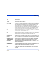
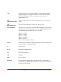
Document conventions
Convention
Element
Blue text (Figure 1)
Blue text represents a cross-reference. In the online version of this guide,
the reference is linked to the target.
Bold
Bold text represents application names, file names, menu items, dialog
box titles, buttons, key names, field names, and literal values that you
type exactly as shown.
Italics
Italic type indicates that you must supply a value. Italic type is also used
for manual titles.
Blue underlined sans serif
font (www.hp.com)
Underlined, blue text represents a website on the Internet. In the online
version of this guide, the reference is linked to the target.
monospace font
Monospace font denotes user input and system responses, such as output
and messages.
Example
The word “example” in italics denotes an example of input or output.
[]
Square brackets indicate an optional parameter.
{}
Braces indicate that you must specify at least one of the listed options.
|
A vertical bar separates alternatives in a list of options.
10
HP StorageWorks Disk Array XP Operating System Configuration Guide: HP-UX
Revision history
About this guide
September 1999
Open-8 emulation added.
January 2000
Content extensively revised and reorganized.
June 2000
Added support for XP512.
Content reorganized and revised.
February 2001
Added appendixes C, D, E, and F.
Added glossary.
April 2003
Changed brand name to StorageWorks.
Added support for OPEN-L and OPEN-V.
Changed CVS to VCS.
November 2003
Revised I/O timeout procedure. Minor update.
August 2004
Updated for XP12000.
July 2005
Updated to include XP10000, Command View XP
Advanced Edition, and Remote Web Console XP.
11
Warranty statement
HP warrants that for a period of ninety calendar days from the date of
purchase, as evidenced by a copy of the invoice, the media on which the
Software is furnished (if any) will be free of defects in materials and
workmanship under normal use.
DISCLAIMER. EXCEPT FOR THE FOREGOING AND TO THE
EXTENT ALLOWED BY LOCAL LAW, THIS SOFTWARE IS
PROVIDED TO YOU “AS IS” WITHOUT WARRANTIES OF ANY
KIND, WHETHER ORAL OR WRITTEN, EXPRESS OR IMPLIED.
HP SPECIFICALLY DISCLAIMS ANY IMPLIED WARRANTIES
OR CONDITIONS OF MERCHANTABILITY, SATISFACTORY
QUALITY, NON-INFRINGEMENT, TITLE, ACCURACY OF
INFORMATIONAL CONTENT, AND FITNESS FOR A
PARTICULAR PURPOSE. Some jurisdictions do not allow exclusions
of implied warranties or conditions, so the above exclusion may not apply
to you to the extent prohibited by such local laws. You may have other
rights that vary from country to country, state to state, or province to
province.
WARNING! YOU EXPRESSLY ACKNOWLEDGE AND AGREE
THAT USE OF THE SOFTWARE IS AT YOUR SOLE RISK. HP
DOES NOT WARRANT THAT THE FUNCTIONS CONTAINED IN
THE SOFTWARE WILL MEET YOUR REQUIREMENTS, OR THAT
THE OPERATION OF THE SOFTWARE WILL BE UNINTERRUPTED,
VIRUS-FREE OR ERROR-FREE, OR THAT DEFECTS IN THE
SOFTWARE WILL BE CORRECTED. THE ENTIRE RISK AS TO THE
RESULTS AND PERFORMANCE OF THE SOFTWARE IS ASSUMED
BY YOU. HP DOES NOT WARRANT OR MAKE ANY
REPRESENTATIONS REGARDING THE USE OR THE RESULTS OF
THE USE OF THE SOFTWARE OR RELATED DOCUMENTATION IN
TERMS OF THEIR CORRECTNESS, ACCURACY, RELIABILITY,
CURRENTNESS, OR OTHERWISE. NO ORAL OR WRITTEN
INFORMATION OR ADVICE GIVEN BY HP OR HP’S AUTHORIZED
REPRESENTATIVES SHALL CREATE A WARRANTY.
12
HP StorageWorks Disk Array XP Operating System Configuration Guide: HP-UX
LIMITATION OF LIABILITY. EXCEPT TO THE EXTENT
PROHIBITED BY LOCAL LAW, IN NO EVENT INCLUDING
NEGLIGENCE WILL HP OR ITS SUBSIDIARIES, AFFILIATES,
DIRECTORS, OFFICERS, EMPLOYEES, AGENTS OR
SUPPLIERS BE LIABLE FOR DIRECT, INDIRECT, SPECIAL,
INCIDENTAL, CONSEQUENTIAL, PUNITIVE OR OTHER
DAMAGES (INCLUDING LOST PROFIT, LOST DATA, OR
DOWNTIME COSTS), ARISING OUT OF THE USE, INABILITY
TO USE, OR THE RESULTS OF USE OF THE SOFTWARE,
WHETHER BASED IN WARRANTY, CONTRACT, TORT OR
OTHER LEGAL THEORY, AND WHETHER OR NOT ADVISED
OF THE POSSIBILITY OF SUCH DAMAGES. Your use of the
Software is entirely at your own risk. Should the Software prove defective,
you assume the entire cost of all service, repair or correction. Some
jurisdictions do not allow the exclusion or limitation of liability for
incidental or consequential damages, so the above limitation may not apply
to you to the extent prohibited by such local laws.
NOTE. EXCEPT TO THE EXTENT ALLOWED BY LOCAL LAW,
THESE WARRANTY TERMS DO NOT EXCLUDE, RESTRICT OR
MODIFY, AND ARE IN ADDITION TO, THE MANDATORY
STATUTORY RIGHTS APPLICABLE TO THE LICENSE OF THE
SOFTWARE TO YOU; PROVIDED, HOWEVER, THAT THE
CONVENTION ON CONTRACTS FOR THE INTERNATIONAL
SALE OF GOODS IS SPECIFICALLY DISCLAIMED AND SHALL
NOT GOVERN OR APPLY TO THE SOFTWARE PROVIDED IN
CONNECTION WITH THIS WARRANTY STATEMENT.
About this guide
13
14
HP StorageWorks Disk Array XP Operating System Configuration Guide: HP-UX
1
Installation
You and your HP service representative each play a role in installation.
Your HP service representative is responsible for installing the disk array
and formatting the disk devices. You are responsible for configuring the
host server for the new devices with assistance from your HP service
representative.
Installation
15
Features and requirements
Ask your HP service representative about the latest supported hardware and
software.
The disk array and host have the following features:
• Storage capacity. The storage capacity for each model is listed
below:
XP128: From 8 to 128 drives for up to 18 TB, 48 FC ports
XP1024: From 8 to 1024 drives for up to 149 TB, 64 FC ports
XP10000: Up to 240 drives for up to 69.2 TB, 48 FC ports
XP12000: Up to 1152 drives for up to 165 TB, 128 FC ports
• Server support. HP-UX-supported processor
• Operating system support. HP-UX, version 10.20, 11.0, or 11i v2
with the latest patches (if any)
Before installing the disk array, ensure the environment conforms to these
requirements:
• Host Bus Adapters (HBAs) Install HBAs and all utilities and
drivers. Refer to the adapter documentation for installation details.
• (Recommended) HP StorageWorks Remote Web Console XP,
Command View XP Advanced Edition or Command View XP with
LUN management feature for configuring disk array ports and
paths
• (Recommended) HP StorageWorks LUN Configuration and
Security Manager XP
16
HP StorageWorks Disk Array XP Operating System Configuration Guide: HP-UX
• (Optional) Other available XP software (some may not be
supported by your array:
HP StorageWorks Business Copy XP
HP StorageWorks Continuous Access XP
HP StorageWorks Continuous Access Extension XP
HP StorageWorks Auto LUN XP
HP StorageWorks Data Exchange XP
HP StorageWorks Resource Manager XP
HP StorageWorks RAID Manager XP
HP StorageWorks Cache LUN XP
HP StorageWorks Auto Path XP
HP StorageWorks Cluster Extension XP
HP StorageWorks Performance Advisor XP
Fibre Channel interface
The XP family of disk arrays supports these Fibre Channel elements:
• Connection speed of 1 Gbps and 2 Gbps
• Short-wave non-OFC (open fiber control) optical interface
• Multimode optical cables with SC or LC connectors
• Public or private arbitrated loop (FC-AL) or direct fabric attach
• Fibre Channel switches
Even though the interface is Fibre Channel, this guide uses the term “SCSI
disk” because disk array devices are defined to the host as SCSI disks.
Installation
17
Device emulation types
The XP family of disk arrays supports these device emulation types:
• OPEN-K/3/8/9/E devices: OPEN-x logical units represent disk
devices. Except for OPEN-V, these devices are based on fixed
sizes. OPEN-V is a user-defined size. Supported emulations
include OPEN-3, OPEN-8, OPEN-9, OPEN-E, OPEN-L, and
OPEN-V devices.
• LUSE devices (OPEN-x*n): Logical Unit Size Expansion (LUSE)
devices combine 2 to 36 OPEN-x devices to create expanded
LDEVs larger than standard OPEN-K/3/8/9/E disk devices. For
example, an OPEN-x LUSE volume created from ten OPEN-x
volumes is designated as OPEN-x*10.
• CVS devices (OPEN-x CVS): Volume Size Configuration (VSC)
defines custom volumes (CVS) that are smaller than normal
fixed-sized logical disk devices (volumes). (OPEN-V is a
CVS-based custom disk size that you determine. OPEN-L does not
support CVS.)
• LUSE (expanded) CVS devices (OPEN-x*n CVS): LUSE CVS
combines CVS devices to create an expanded device. This is done
by first creating CVS custom-sized devices and then using LUSE
to combine from 2 to 36 CVS devices. For example, if three
OPEN-9 CVS volumes are combined to create an expanded device,
this device is designated as OPEN-9*3-CVS.
Failover
The XP family of disk arrays supports many standard software products
that provide host, application, or I/O path failover and management.
The following are supported for HP-UX:
• HP Multi-Computer/ServiceGuard (MC/ServiceGuard) software for
application failover
• Alternate link for I/O path failover (included in HP-UX)
• Logical volume management (included in HP-UX)
18
HP StorageWorks Disk Array XP Operating System Configuration Guide: HP-UX
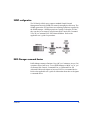
SNMP configuration
The XP family of disk arrays supports standard Simple Network
Management Protocol (SNMP) for remotely managing the disk array. The
SNMP agent on the SVP performs error-reporting operations requested by
the SNMP manager. SNMP properties are usually set from the SVP but
they can also be set remotely using Remote Web Console XP, Command
View XP, or Command View XP Advanced Edition. Refer to the
applicable user’s guide for procedures.
RAID Manager command devices
RAID Manager manages Business Copy (BC) or Continuous Access (CA)
operations from a host server. To use RAID Manager with BC or CA, you
use Remote Web Console, Command View, or Command View XP
Advanced Edition to designate at least one LDEV as a command device.
Refer to the applicable user’s guide for information about how to designate
a command device.
Installation
19
Installation procedures
Perform these actions to install and configure the disk array:
1. Install and configure the disk array (see page 21)
• Setting the host mode for the disk array ports
• Setting the System Option Modes
• Configuring the Fibre Channel ports
2. Install and configure the host (see page 26)
• Loading the OS and software
• Installing and configuring the HBAs
• Clustering and fabric zoning
• Fabric zoning and LUN security for multiple operating systems
3. Connect the disk array (see page 29)
• Defining the paths
• Verifying HBA installation
• Verifying device recognition
4. Configure disk array devices (see page 35)
• Verifying the device files and drivers
• Creating the device files
• Creating the physical volumes
• Creating new volume groups
• Creating logical volumes
• Creating the file systems
• Setting the I/O timeout parameter
• Creating the mount directories
• Mounting and verifying the file systems
• Setting and verifying the auto-mount parameters
20
HP StorageWorks Disk Array XP Operating System Configuration Guide: HP-UX
Install and configure the disk array
The HP service representative performs these tasks:
• Assembling hardware and installing software
• Loading the microcode updates
• Installing the channel adapters (CHAs) and cabling
• Installing and formatting devices
After these tasks are finished, you will use Remote Web Console,
Command View, Command View XP Advanced Edition, or LUN
Configuration and Security Manager to complete the remaining tasks listed
below. If you do not have these programs, your HP service representative
can perform these tasks for you.
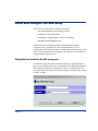
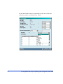
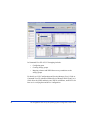
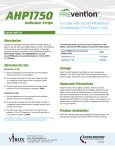
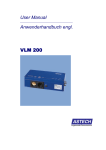
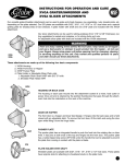
Setting the host mode for the disk array ports
The disk array ports have host modes that must be set depending on the
host you use. After the disk array is installed use LUN Manager in Remote
Web Console XP (shown), Command View XP, or Command View XP
Advanced Edition to set the host mode for each port. The host mode setting
for HP-UX is 08.
Installation
21
For the XP1024/XP128 arrays, the host mode can also be set at the port
information window in Command View XP AE.
22
HP StorageWorks Disk Array XP Operating System Configuration Guide: HP-UX
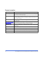
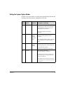
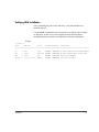
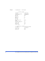
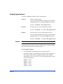
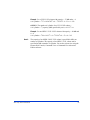
Setting the System Option Modes
The HP service representative sets the System Option Mode(s) based on the
operating system and software configuration of the host.
Mode
Level
HA
Software
140
Optional
None
Description and Usage
ON: Response to the Inquiry command is
changed, and the volume can be used from
VeritasNetBackUP in heterogeneous OS
configuration, such as HP-UX.
OFF: Normal response to the Inquiry
command.
186
254
Mandatory
Optional
Veritas
Database
Editions/
Advanced
Cluster
ON: Mandatory setting when VERITAS
Database Editions/Advanced Cluster is
connected.
Veritas
Database
Editions
Change the response of reserve conflict status
to Read Capacity, Verify, and Start Stop Unit.
OFF: VERITAS Database Editions/Advanced
Cluster should not be connected with this
setting.
ON: Normal end is reported.
OFF: Reserve conflict status is reported.
280
Optional
HP-UX Ghost LUN Remove
OS version: HP-UX 11.0 and later.
ON: When the host scans the LUNS on the
port, the disk array is not represented in the
device list for HP-UX.
OFF: When the host scans the LUNS on the
port, the disk array is represented in the device
list for HP-UX.
Installation
23
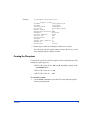
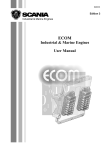
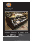
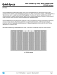
Configuring the Fibre Channel ports
Configure the disk array Fibre Channel ports by using Remote Web
Console (shown), Command View, or Command View XP AE. Select the
settings for each port based on your storage area network topology. Use
switch zoning if you connect different types of hosts to the array through
the same switch.
Fibre Address
In fabric environments, the port addresses are assigned automatically. In
arbitrated loop environments, set the port addresses by selecting a unique
arbitrated loop physical address (AL-PA) or loop ID for each port.
24
HP StorageWorks Disk Array XP Operating System Configuration Guide: HP-UX
Fabric and Connection parameter settings
Set each array port to FABRIC ON or OFF with connections of
POINT-TO-POINT or FC-AL as shown in the following table and figures.
For detailed topology information, refer to the HP StorageWorks SAN
Design Reference Guide on the hp.com website.
Installation
Fabric
Connection
parameter parameter
Provides
ON
FC-AL
Not supported
ON
Direct Fabric Attach
F-port (fabric port)
OFF
FC-AL
AL-port (private arbitrated loop)
OFF
Direct Fabric Attach
Not supported
25
Install and configure the host
This section explains how to install and configure the host and host bus
adapters (HBAs) that connect the host to the disk array.
Loading the OS and software
Follow the manufacturer’s instructions to load the operating system and
software onto the host. Load all OS patches and configuration utilities
supported by HP and the HBA manufacturer.
Installing and configuring the HBAs
Install and configure the host bus adapters using the HBA manufacturer’s
instructions.
26
HP StorageWorks Disk Array XP Operating System Configuration Guide: HP-UX
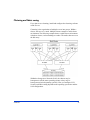
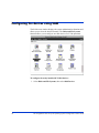
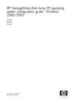
Clustering and fabric zoning
If you plan to use clustering, install and configure the clustering software
on the servers.
Clustering is the organization of multiple servers into groups. Within a
cluster, each server is a node. Multiple clusters compose a multi-cluster
environment. The following example shows a multi-cluster environment
with three clusters, each containing two nodes. The nodes share access to
the disk array.
Within the Storage Area Network (SAN), the clusters may be
homogeneous (all the same operating system) or they may be
heterogeneous (mixed operating systems). How you configure LUN
Security and fabric zoning depends on the operating system mix and the
SAN configuration.
Installation
27
Fabric zoning and LUN security for multiple operating systems
You can connect multiple clusters of various operating systems to the same
switch and fabric using appropriate zoning and LUN security as follows:
• Host zones must contain only homogeneous operating systems.
• Storage port zones may overlap if more than one operating system
needs to share an array port.
• Heterogeneous operating systems may share an XP array port if you
use Secure Manager and set the appropriate host group and mode.
All others must connect to a dedicated XP array port.
• Use Secure Manager for LUN isolation when multiple hosts connect
through a shared array port. Secure Manager provides LUN
security by allowing you to restrict which LUNs each host can
access.
Environment
Standalone SAN
(non-clustered)
Clustered SAN
Multi-Cluster
SAN
28
OS Mix
homogeneous (a single OS
type present in the SAN)
heterogeneous (more than one
OS type present in the SAN)
homogeneous (a single OS
type present in the SAN)
heterogeneous (more than one
OS type present in the SAN)
homogeneous (a single OS
type present in the SAN)
heterogeneous (more than one
OS type present in the SAN)
Fabric Zoning
Not required
Required
Not required
Required
Not required
Required
LUN Security
Must be used when multiple
hosts connect through a
shared port
Must be used when multiple
cluster nodes connect through
a shared port
Must be used when multiple
cluster nodes connect through
a shared port
HP StorageWorks Disk Array XP Operating System Configuration Guide: HP-UX
Connect the disk array
The HP service representative connects the disk array to the host by:
1. Verifying operational status of the disk array channel adapters, LDEVs,
and paths.
2. Connecting the Fibre Channel cables between the disk array and the
fabric switch or host.
3. Verifying the ready status of the disk array and peripherals.
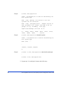
Defining the paths
Use Remote Web Console (shown), Command View, or Command View
XP AE to define paths (LUNs) between hosts and volumes in the disk
array.
This process is also called “LUN mapping.” In Remote Web Console and
Command View, LUN mapping includes:
• Configuring ports
• Setting LUN security
• Creating host groups
• Assigning host bus adapter WWNs to host groups
• Mapping volumes to host groups (by assigning LUNs)
Installation
29
In Command View XP AE, LUN mapping includes:
• Configuring ports
• Creating storage groups
• Mapping volumes and WWN/host access permissions to the
storage groups
For details see LUN Configuration and Security Manager User’s Guide or
Command View XP Advanced Edition Device Manager Web Client User’s
Guide. Note the LUNS and their ports, WWNs, nicknames, and LDEVs for
later use in verifying host and device configuration.
30
HP StorageWorks Disk Array XP Operating System Configuration Guide: HP-UX
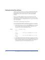
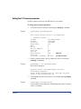
Verifying HBA installation
After configuring the ports on the disk array, verify that the HBAs are
installed properly.
Use the ioscan –f command, and verify that the rows shown in the example
are displayed. If these rows are not displayed, check the host adapter
installation (hardware and driver installation) or the host configuration.
Example
# ioscan -f
Class
I
H/W Path
Driver
S/W State H/W Type
Description
===============================================================================================
...
fc
0
8/12
fcT1
CLAIMED
INTERFACE
HP Fibre Channel Mass Storage Adapter
lan
1
8/12.5
fcT1_cntl CLAIMED
INTERFACE
HP Fibre Channel Mass Storage Cntl
fcp
0
8/12.8
fcp
CLAIMED
INTERFACE
FCP Protocol Adapter
ext_bus
2
8/12.8.0.255.0
fcpdev
CLAIMED
INTERFACE
FCP Device Interface
...
Installation
31
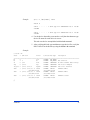
Verifying device recognition
Verify that the HP-UX system recognizes the new devices on the disk
array.
If the SCSI paths were defined after the system is powered on, you must
halt and restart the system to allow the system to recognize the new
devices.
To verify device recognition:
1. Log in to the system as root.
2. Display the device data to verify that the system recognizes the newly
installed devices on the disk array. Use the ioscan –fn command to
display the device data.
On a system with a large LUN configuration, HP-UX may not build
device files on all LUNs. Enter insf –e to build all missing device files.
Example
# ioscan -fn
class
I H/W Path
Driver
S/W State H/W Type
Description
==========================================================================
bc
fc
lan
fcp
ext_bus
target
disk
disk
ext_bus
target
ctl
6
1
2
1
6
9
4
5
7
10
5
14
14/12
14/12.5
14/12.8
14/12.8.0.0.0
14/12.8.0.0.0.0
14/12.8.0.0.0.0.0
14/12.8.0.0.0.0.1
14/12.8.0.255.0
14/12.8.0.255.0.0
14/12.8.0.255.0.0.0
ccio
fcT1
fcT1_cntl
fcp
fcpmux
tgt
sdisk
sdisk
fcpdev
tgt
sctl
CLAIMED
CLAIMED
CLAIMED
CLAIMED
CLAIMED
CLAIMED
CLAIMED
CLAIMED
CLAIMED
CLAIMED
CLAIMED
BUS_NEXUS
INTERFACE
INTERFACE
INTERFACE
INTERFACE
DEVICE
DEVICE
DEVICE
INTERFACE
DEVICE
DEVICE
I/O Adapter HP Fibre Channel Mass
Storage Adapter HP Fibre Channel Mass
Storage Cntl /dev/fcms2
FCP Protocol Adapter HP A3308 FCP-SCSI MUX
Interface
HP OPEN-9 /dev/dsk/c6t0d0/dev/rdsk/c6t0d0
HP OPEN-9*2 /dev/dsk/c6t0d1 /dev/rdsk/c6t0d1
FCP Device Interface
HP HPA3308 /dev/rscsi/c7t0d0
In the example:
HP OPEN-9 device: SCSI bus number = 14/12, bus instance = 6, SCSI
target ID = 0, LUN = 0.
HP OPEN-9*2 device: SCSI bus number = 14/12, bus instance = 6,
SCSI target ID = 0, LUN = 1.
If UNKNOWN is displayed for a disk, the HP 9000 system may not be
configured properly. Refer to the HP documentation or contact HP
32
HP StorageWorks Disk Array XP Operating System Configuration Guide: HP-UX
customer support for assistance with the HP 9000 system or the
HP-UX operating system.
3. Enter the device data for each disk array device in a table. See “Path
worksheet” on page 62.
4. Construct the device file name for each device, using the device
information, and enter the file names in your table. Use the following
formula to construct the device file name:
cxtydz
where
x = SCSI bus instance number
y = SCSI target ID
z = LUN
c stands for controller, t stands for target ID, and d stands for device.
The numbers x, y, and z are hexadecimal.
Example
SCSI bus
instance number
Hardware path SCSI TID
LUN
File name
00
14/12.6.0
6
0
c6t0d0
00
14/12.6.1
6
1
c6t0d1
5. Verify that the SCSI TIDs correspond to the assigned port address for
all connected ports (see mapping tables on page 63 in Appendix B, for
values). If so, the logical devices are recognized properly.
If the logical devices are not recognized properly:
• Check the AL-PA for each port using the LUN Manager software.
• If the same port address is set for multiple ports on the same loop
(AL with HUB), all port addresses except one changed to another
value, and the relationship between AL-PA and TID does not
correspond to the mapping given in Appendix B (page 63), set a
Installation
33
different address for each port, reboot the server, and then verify
new device recognition again.
• If unused device information remains, the TID-to-AL-PA mapping
will not correspond to the mapping given in Appendix B (page 63).
Renew the device information, and then verify new device
recognition again.
34
HP StorageWorks Disk Array XP Operating System Configuration Guide: HP-UX
Configure disk array devices
Disk arrays are configured using the same procedure for configuring any
new disk on the host. This includes the following procedures:
1. Verifying the device files and drivers (see page 36)
2. Creating the device files (see page 38)
3. Creating the physical volumes (see page 41)
4. Creating new volume groups (see page 42)
5. Creating logical volumes (see page 45)
6. Creating the file systems (see page 47)
7. Setting the I/O timeout parameter (see page 49)
8. Creating the mount directories (see page 50)
9. Mounting and verifying the file systems (see page 51)
10. Setting and verifying the auto-mount parameters (see page 52)
The HP-UX system uses the Logical Volume Manager (LVM) to manage
the OPEN-x devices on the disk array. The instructions in this section do
not explicitly cover all LVM configuration issues. For further information
on LVM configuration, see the HP-UX user documentation.
HP System Administrator Manager (SAM) can be used instead of UNIX
commands to configure SCSI disk devices. See appendix C (page 73) for
further information.
Installation
35
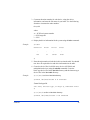
Verifying the device files and drivers
The device files for new devices are usually created automatically during
HP-UX startup. Each device must have a block-type device file in the
/dev/dsk directory and a character-type device file in the /dev/rdsk
directory.
However, some HP-compatible systems do not create the device files
automatically. If verification shows that the device files were not created,
follow the instructions in “Creating the device files” (page 38) to create the
device files manually.
This procedure verifies both types of device files.
To verify that the device files for the disk array devices were created:
1. Display the block-type device files in the /dev/dsk directory using the
ls –l command with the output piped to more. Verify there is one
block-type device file for each disk array device.
Example
# ls –l /dev/dsk | more
Total 0
brw-r - - - - - 1 bin sys 28 0x006000 Dec 6 15:08
c6t0d0
brw-r - - - - - 1 bin sys 280 0x06100 Dec 6 15:08
c6t0d1
2. Verify that the block-type device file name for each device is correct.
3. Display the character-type device files in the /dev/rdsk directory using
the ls –l command with the output piped to more. Verify that there is
one character-type device file for each disk array device.
36
HP StorageWorks Disk Array XP Operating System Configuration Guide: HP-UX
Example
# ls –l /dev/rdsk | more
Total 0
crw-r - - - - c6t0d0
1 bin sys 177 0x006000 Dec 6 15:08
crw-r - - - - c6t0d1
1 bin sys 177 0x006100 Dec 6 15:08
4. Use the device data table you created to verify that the character-type
device file name for each device is correct.
This task can also be accomplished with the lssf command.
5. After verifying the block-type and character-type device files, verify the
HP-UX driver for the disk array using the ioscan –fn command.
Example
# ioscan -fn
Class
I
H/W Path
Driver
S/W State H/W Type
Description
=============================================================================================
bc
0
root
CLAIMED
BUS_NEXUS
bc
1
8
bc
CLAIMED
BUS_NEXUS
Bus Converter
fc
0
8/12
fcT1
CLAIMED
INTERFACE
HP Fibre Channel Mass Storage
fcp
0
8/12.8
fcp
CLAIMED
INTERFACE
FCP Protocol Adapter
ext_bus
2
8/12.8.0.255.0
fcpdev
CLAIMED
INTERFACE
FCP Device Interface
disk
3
8/12.8.8.255.0.6.0
sdisk
CLAIMED
DEVICE
HITACHI OPEN-9
/dev/dsk/c2t6d0
disk
4
8/12.8.8.255.0.6.1
sdisk
/dev/dsk/c2t6d1
disk
5
8/12.8.8.255.0.8.0
sdisk
/dev/dsk/c2t8d0
/dev/rdsk/c2t6d0
CLAIMED
DEVICE
HITACHI OPEN-9
/dev/rdsk/c2t6d1
CLAIMED
DEVICE
HITACHI 3390*3B
/dev/rdsk/c2t8d0
:
#
Installation
37
Creating the device files
If the device files were not created automatically when the system was
restarted, use the insf –e command in the /dev directory to create the device
files. After this command is executed, repeat the procedures in the previous
section (page 36) to verify new device recognition and the device files and
driver.
Example
# insf -e
insf: Installing special files for mux2 instance 0
address 8/0/0
:
:
:
:
:
:
:
:
#
Failure of the insf –e command indicates a SAN problem.
If the device files for the new disk array devices cannot be created
automatically, you must create the device files manually using the mknod
command as follows:
1. Retrieve the device information you recorded earlier.
2. Construct the device file name for each device, using the device
information, and enter the file names in your table. Use the following
formula to construct the device file name:
cxtydz
where
x = SCSI bus instance number
y = SCSI target ID
z = LUN
c stands for controller, t stands for target ID, and d stands for device.
The numbers x, y, and z are hexadecimal.
38
HP StorageWorks Disk Array XP Operating System Configuration Guide: HP-UX
3. Construct the minor number for each device, using the device
information, and enter the file names in your table. Use the following
formula to construct the minor number:
0xxxyz00
where
xx = SCSI bus instance number
y = SCSI target ID
z = LUN
4. Display the driver information for the system using the lsdev command.
Example
# lsdev
Character
Block
:
:
188
31
Driver
Class
:
sdisk
:
disk
#
5. Enter the major numbers for the device drivers into the table. You should
now have all required device and driver information in the table.
6. Create the device files for all disk array devices (SCSI disk and
multiplatform devices) using the mknod command. Create the
block-type device files in the /dev/dsk directory and the character-type
device files in the /dev/rdsk directory.
Example
# cd /dev/dskGo to /dev/dsk directory.
# mknod /dev/dsk/c2t6d0 b 31 0x026000
Create block-type file.
File name, b=block-type, 31=major #, 0x026000= minor
#
# cd /dev/rdskGo to /dev/rdsk directory.
# mknod /dev/rdsk/c2t6d0 c 188 0x026000
Installation
39
Create character-type file.
File name, c=character-type, 177=major #,
0x026000=minor #
:
#
The character-type device file is required for volumes used as raw
devices (for example, 3390-3A/B/C). The block-type device file is not
required for volumes used as raw devices.
If you need to delete a device file, use the rm –i command.
Example of a completed device data table
Bus
no.
Instance Disk
(XX)
no.
H/W path
Driver
Device
type
TID
(Y)
Major # Major #
for char. for block
LUN Device
Minor #
files
files
(Z)
file
0xXXYZ00
8/12
02
3
8/12.8.8.255.0.6.0 sdisk
OPEN-9 6
0
c2t6d0
0x026000
188
31
8/12
02
4
8/12.8.8.255.0.6.1 sdisk
OPEN-9 6
1
c2t6d1
0x026100
188
31
8/12
02
5
8/12.8.8.255.0.8.0 sdisk
3390-3B 8
0
c2t8d0
0x028000
188
31
40
HP StorageWorks Disk Array XP Operating System Configuration Guide: HP-UX
Creating the physical volumes
A physical volume must be created for each new SCSI disk device.
To create the physical volumes:
1. Use the pvcreate command to create the physical volumes with the
character-type device file as the argument. Specify the /dev/rdsk
directory.
Example
# pvcreate /dev/rdsk/c6t0d0
Physical volume "/dev/rdsk/c6t0d0" has been
successfully created.
:
# pvcreate /dev/rdsk/c6t0d1
Physical volume "/dev/rdsk/c6t0d1" has been
successfully created.
Do not use the –f option with the pvcreate command. This option
creates a new physical volume forcibly and overwrites the existing
volume. If you accidentally enter the character-type device file for an
existing volume, you will lose the data on that volume.
2. Repeat step 1 for each OPEN-x device on the disk array.
Installation
41
Creating new volume groups
You must create new volume groups for the new physical volumes. If
desired, you can also add any of the volumes on the disk array to existing
volume groups using the vgextend command. The physical volumes that
make up one volume group can be located either in the same disk array or
in other disk arrays.
To allow more volume groups to be created, use SAM to modify the
HP-UX system kernel configuration. See appendix C (page 73) for details.
To create volume groups:
1. Use the vgdisplay command to display the existing volume groups.
2. Choose a unique name for the new volume group (for example: vg06).
3. Create the directory for the new volume group.
Example
# mkdir /dev/vg06
4. Use the ls –l command (with the output piped to grep to display only
the files containing “group”) to display the minor numbers for the
existing group files.
Example
# ls –1 /dev/vg* | grep group
crw-rw-rw 1 root root 64
group
0x0000000
Nov7 08:13
:
5. Choose a unique minor number for the new group file in sequential order
(for example, when existing volume groups are vg00-vg05 and the next
group name is vg06, use minor number 06 for the vg06 group file).
The minor numbers are hexadecimal (for example, the 10th minor
number is 0x0a0000).
6. Use mknod to create the group file for the new directory. Specify the
volume group name, major number, and minor number. The major
number for all group files is 64.
42
HP StorageWorks Disk Array XP Operating System Configuration Guide: HP-UX
Example
In this example: group name = vg06, major number of group file = 64,
minor number of existing group file = 06 (which must be unique for
each volume group), and c = character.
# mknod /dev/vg06/group c 64 0x060000
:
7. Create the volume group.
To allocate more than one physical volume to the new volume group,
add the other physical volumes, separated by a space.
Example
# vgcreate /dev/vg06 /dev/dsk/c6t0d0
Volume group "/dev/vg06" has been successfully
created.
Volume group configuration for /dev/vg06 has been
saved in /etc/1vmconf/vg06.conf.
For Logical Unit Size Expansion (LUSE) volumes that contain more
than 17 OPEN-8/9 LDEVs or more than 7043 MB
(OPEN-8/9*n-CVS), use the –s and –e physical extent (PE)
parameters of the vgcreate command. See “LUSE device parameters”
(page 68).
If you need to delete a volume group, use the vgremove command (for
example, vgremove /dev/vgnn). If the vgremove command does not
work because the volume group is not active, use the vgexport
command (for example, vgexport /dev/vgnn).
8. Use the vgdisplay command to verify that the new directory was
created.
9. Use vgdisplay –v to verify that the volume group was created correctly.
The –v option displays the detailed volume group information.
Installation
43
Example
# vgdisplay –v /dev/vg06
- - -
Volume groups
VG Name
VG Write Access
VG Status
Max LV
Cur LV
Open LV
Max PV
Cur PV
Act PV
Max PE per PV
VGDA
PE Size (Mbytes)
Total PE
Alloc PE
Free PE
Total PVG
- - /dev/vg06
read/write
available
255
0
0
16
1
1
1016
2
4
586
0
586
0
- - Physical Volumes - - PV Name
/dev/dsk/c6t0d0
PV Status
available
Total PE
586
Free PE
586
44
HP StorageWorks Disk Array XP Operating System Configuration Guide: HP-UX
Creating logical volumes
Use these commands for logical volume configuration:
lvremove
Deletes a logical volume.
Any file system attached to the logical volume must be
unmounted before executing the lvremove command.
Example: lvremove /dev/vgnn/lvolx
lvextend
Increases the size of an existing logical volume.
Example: lvextend –L size /dev/vgnn/lvolx
lvreduce
Decreases the size of an existing logical volume.
Any file system attached to the logical volume must be
unmounted before executing the lvreduce command.
Example: lvreduce –L size /dev/vgnn/lvolx
Caution
Data within the file system can be lost after execution of lvreduce.
Create logical volumes after you create volume groups. A logical volume
must be created for each new SCSI disk device
To create logical volumes:
1. Use the lvcreate –L command to create a logical volume.
Specify the volume size (in megabytes) and the volume group for the
new logical volume. HP-UX assigns the logical volume numbers
automatically (lvol1, lvol2, lvol3). Use the following capacity values
for the size parameter:
OPEN-K = 1740
OPEN-3 = 2344
OPEN-8 = 7004
OPEN-9 = 7004
OPEN-E = 13888
Installation
45
OPEN-L = 34756
OPEN-V = 61432
To calculate S1 for CVS, LUSE, and CVS LUSE volumes, first use
the vgdisplay command to display the physical extent size (PE Size)
and usable number of physical extents (Free PE) for the volume.
Calculate the maximum size value (in MB) as follows:
S1 = (PE Size) × (Free PE)
Logical volumes can span multiple physical volumes. Use the
diskinfo command for extended LUNs.
Example
Create an OPEN-3 logical volume the size of the physical volume,
using 2344 for the size parameter. An OPEN-9 volume uses 7040 for
the size parameter to create a logical volume the size of the physical
volume.
# lvcreate –L 2344 /dev/vg06
Logical volume "/dev/vg06/lvol1" has been
successfully created with character device
"/dev/vg06/rlvol1".
Logical volume "/dev/vg06/lvol1" has been
successfully extended.
Volume Group configuration for /dev/vg06 has been
saved in /etc/1vmconf/vg06.cof.
2. Use the lvdisplay command to verify that the logical volume was
created correctly.
46
HP StorageWorks Disk Array XP Operating System Configuration Guide: HP-UX
Example
# lvdisplay /dev/vg06/lvol1
- - - Logical volume - - LV Name
/dev/vg06/lvol1
VG Name
/dev/vg06
LV Permission
read/write
LV Status
available/syncd
Mirror copies
0
Consistency Recovery MWC
Schedule
parallel
LV Size (Mbytes)
2344
Current LE
586
Allocated PE
586
Stripes
0
Stripe Size (Kbytes) 0
Bad block
on
Allocation
strict
3. Repeat steps 1 and 2 for each logical volume to be created.
You can create only one logical volume at a time. However, you can
verify multiple logical volumes at a time.
Creating the file systems
Create the file system for each new logical volume on the disk array. The
default file system types are:
• HP-UX OS version 10.20 = hfs or vxfs, depending on entry in the
/etc/defaults/fs file
• HP-UX OS version 11.0 = vxfs
• HP-UX OS version 11.i = vxfs
To create file systems:
1. Use the newfs command to create the file system using the logical
volume as the argument.
Installation
47
Example
# newfs /dev/vg06/rlvol1
newfs: /etc/default/fs is used for determining the
file system type
mkfs (hfs): Warning -272 sectors in the last
cylinder are not allocated.
mkfs (hfs): /dev/vg06/rlvol1 - 2400256 sectors in
3847 cylinders of 16 tracks, 2547.9MB in 241 cyl
groups (16 c/g, 10.22Mb/g, 1600 ig/g)
Super block backups (for fsck -b) at:
16,
10040, 20064, 30038, 40112, 50136,
70184, 80208, 90232, . . . 2396176
Example
60160,
# newfs /dev/vg06/rlvol1Create file system
newfs: / etc/default/fs is used for determining the
file system type
mkfs (hfs): ...
:
7188496, 7198520, 7208544
#
Example
# newfs -F vxfs /dev/vg06/rlvol1Specify file system type
:
# newfs -F hfs /dev/vg06/rlvol2
2. Repeat step 1 for each logical volume on the disk array.
48
HP StorageWorks Disk Array XP Operating System Configuration Guide: HP-UX
Setting the I/O timeout parameter
Set the I/O timeout value for each disk device to 30 seconds.
To change the I/O timeout parameter:
1. Verify the current I/O timeout value using the pvdisplay command:
Example
# pvdisplay /dev/dsk/c0t6d0
This causes current values to be displayed:
--- Physical volumes --PV Name
/dev/dsk/c0t6d0
VG Name
/dev/vg06
PV Status
available
Allocatable
yes
VGDA
2
Cur LV
1
PE Size (Mbytes)
4
Total PE
586
Free PE
0
Allocated PE
586
[OPEN-9]
Stale PE
0
IO Timeout (Seconds) default
[I/O timeout value]
2. If the I/O timeout value is not 30, change the value to 30 using the
pvchange -t command:
Example
# pvchange -t 30 /dev/dsk/c0t6d0
This result is displayed:
Physical volume "/dev/dsk/c0t6d0" has been
successfully changed.
Volume Group configuration for /dev/vg06 has been
saved in /etc/lvmconf/vg06.cof
3. Verify that the new I/O timeout value is 30 seconds using the pvdisplay
command:
Example
# pvdisplay /dev/dsk/c0t6d0
Current values are now displayed, confirming that the new I/O timeout
value is 30 seconds:
Installation
49
--- Physical volumes --PV Name
/dev/dsk/c0t6d0
VG Name
/dev/vg06
PV Status
available
:
Stale PE
0
IO Timeout (Seconds) 30
[New I/O timeout value]
4. Repeat the above steps for each new disk that is connected to the system.
Creating the mount directories
Create a mount directory for each logical volume. Choose a unique name
for each mount directory that identifies the logical volume.
Example
The following example shows the root directory as the location for the
mount directories.
To create a mount directory for each logical volume:
1. Use mkdir with the new mount directory name as the argument to create
the mount directory.
# mkdir /AHPMD-LU00
2. Use the ls –x command to verify the new mount directory.
# ls -x
AHPMD-LU00
floppy
bin
home
dev
hstsboof
device
kadb
etc
export
kernel
lib
3. Repeat steps 1 and 2 for each logical volume on the disk array.
50
HP StorageWorks Disk Array XP Operating System Configuration Guide: HP-UX
Mounting and verifying the file systems
After the mount directories have been created, mount and verify the file
system for each logical volume.
To mount and verify the file systems:
1. Use mount to mount the file system for the volume.
Example
# mount /dev/vg06/lvol1
/AHPMD-LU00
2. Repeat step 1 for each logical volume on the disk array.
If you need to unmount a file system, use the unmount command.
3. Use the bdf command to verify that the file systems are correct. The
capacity is listed under Kbytes.
Example
# bdf
Filesystem
Kbytes used avail %used Mounted on
/ldev/vg00/lvol1 59797 59364
0 100% /
:
/ldev/vg06/lvol1 2348177
9 2113350
0% /AHPMD-LU00
4. As a final verification, perform some basic UNIX operations (for
example file creation, copying, and deletion) on each logical device to
make sure that the devices on the disk array are fully operational.
Example
#cd /AHPMD-LU00
#cp /bin/vi /AHPMD-LU00/vi.back1
#ls -l
drwxr-xr-t
2 root
11:35 lost+found
root
-rwxr-xr-x
1
11:41 vi.back1
sys
root
8192 Mar
15
217088 Mar
15
#cp vi.back1 vi.back2
#ls -l
Installation
51
drwxr-xr-t
2 root
11:35 lost+found
root
8192 Mar
15
-rwxr-xr-x
1
11:41 vi.back1
root
sys
217088 Mar
15
-rwxr-xr-x
1
11:52 vi.back2
root
sys
217088 Mar
15
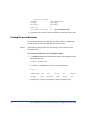
Setting and verifying the auto-mount parameters
Set up and verify the auto-mount parameters for each new volume. The
/etc/checklist file (which can also be called the /etc/fstab file) contains the
auto-mount parameters for the logical volumes.
To set up and verify the auto-mount parameters:
1. Edit the /etc/checklist (/etc/fstab) file to add a line for each
OPEN-x device on the disk array. This example and the following table
show the auto-mount parameters.
Example
#cp -ip /etc/checklist /etc/checklist.standard
#vi /etc/checklist
/dev/vg00/lvol1
/
hfs
rw
/dev/vg00/lvol2
swap
ignore
rw
:
/dev/vg06/lvol1
/AHPMD-LU00
hfs
defaults
/dev/vg06/lvol2
/AHPMD-LU01
hfs
defaults
P1
52
P2
P3
P4
0
0
1
0
#
#
root
primary swap
0
0
2
2
#
#
AHPMD-LU00
AHPMD-LU01
P5
P6
P7
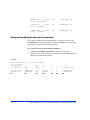
HP StorageWorks Disk Array XP Operating System Configuration Guide: HP-UX
Parameter Name
Enter
P1
Device to mount
Block-type device file name
P2
Mount point
Mount directory name
File system
Type of file system (for example,
hfs, vxfs)
Mount options
“defaults” or other appropriate
mount options
P5
Enhance
0
P6
File system check Order for performing file system
(fsck pass)
checks
P7
Comments
P3
P4
Comment statement
2. Reboot the system.
3. Use the bdf command to verify the file system again.
Installation
53
54
HP StorageWorks Disk Array XP Operating System Configuration Guide: HP-UX
2
Troubleshooting
This section includes resolutions for various error conditions you may
encounter.
If you are unable to resolve an error condition, ask your HP support
representative for assistance. See “Calling the HP support center” on
page 59.
Troubleshooting
55
Error conditions
Depending on your system configuration, you may be able to view error
messages as follows:
• In Remote Web Console (Status tab)
• In Command View Advanced Edition (“Alerts” panel).
• In Command View (Event History or Event Notification panels).
Error Condition
Recommended Action
The logical devices are not
recognized by the host.
Verify that the READY indicator lights on the disk array are ON.
Verify that fiber cables are correctly installed and firmly connected.
Verify that the target IDs are properly configured. The LUNs for each
TID must start at 0 and continue sequentially without skipping any
numbers.
Verify that the TIDs/WWNs on each bus are unique. Do not install two
devices with the same ID on the same bus.
Recheck the buses for new devices.
Verify that LUSE devices are not intermixed with normal LUNs on the
same port.
Verify that the maximum number of LUSE devices per port has not
been exceeded.
Verify that the disk array host mode is set correctly.
The host does not reboot
If you power off the host without executing the shutdown process, wait
properly after hard shutdown. three minutes to allow the disk array’s internal timeout process to
purge queued commands. If the host restarts while the disk array is
processing queued commands, the host may not reboot successfully.
56
HP StorageWorks Disk Array XP Operating System Configuration Guide: HP-UX
Error Condition
Recommended Action
Physical volumes cannot be
created (pvcreate).
Verify that the disk array logical devices are correctly formatted.
Verify that the character-type device file exists.
Verify that the correct character-type device file name is used with
pvcreate (for example, /dev/rdsk/...).
Volume group cannot be
created (vgcreate).
Verify that the directory for the new volume group exists.
Verify that the control file exists.
Verify that the correct major number (64) and minor number are used
with mknod.
Verify that the block-type device file exists and is entered correctly
with vgcreate.
Verify that the physical volume is not already allocated to another
volume group.
Logical volumes cannot be
created (lvcreate).
Verify that the volume capacity for OPEN-x volumes is not greater
than the maximum capacity allowed. See the Device Emulations
Appendix.
Verify that the capacity of the volume group is not less than the total
capacity of the partitioned logical volume.
The file system cannot be
created (newfs command).
Verify that the character-type device file is entered correctly with
newfs (for example, /dev/vg01/r/vo/x).
A file system is not mounted Verify that the host was restarted correctly.
after rebooting.
Verify that the file system attributes are correct.
Verify that the auto-mount information in the /etc/checklist
(/etc/fstab) file is correct.
Troubleshooting
57
Error Condition
Recommended Action
The disk array performs a
Reboot the host.
self reboot because the disk
array was busy or it logged a
panic message.
The disk array responds “Not Contact HP.
Ready” or the disk array has
displayed “Not Ready” and
timed out.
The host detects a parity
error.
Check the HBA and make sure it was installed properly.
Reboot the host.
The host hangs or devices are Make sure there are no duplicate disk array TIDs and that disk array
declared and the host hangs. TIDs do not conflict with any host TIDs.
58
HP StorageWorks Disk Array XP Operating System Configuration Guide: HP-UX
Calling the HP support center
If you are unable to resolve an error condition, contact the HP support
center for assistance.
Contact Information
In North America, call technical support at 1-800-633-3600, available 24
hours a day, 7 days a week.
Outside North America, call technical support at the location nearest you.
The HP web site lists telephone numbers for worldwide technical support
at: http://www.hp.com/support. From this web site, select your country.
Before you call
Be sure to have the following information available:
• Technical support registration number (if applicable)
• Product serial numbers
• Product model names and numbers
• Applicable error messages
• Operating system type and revision level
• Detailed, specific questions
Troubleshooting
59
60
HP StorageWorks Disk Array XP Operating System Configuration Guide: HP-UX
A
Worksheets
Worksheets
61
Path worksheet
Bus
no.
62
Instance Disk H/W path
(XX)
no.
Driver Device TID
type
(Y)
LUN Device Minor #
Major # Major #
(Z) file
0xXXYZ00 for char. for block
files
files
HP StorageWorks Disk Array XP Operating System Configuration Guide: HP-UX
B
Disk array device emulations
This appendix provides information about supported emulations and device
type specifications. Some parameters may not be relevant to your array.
Consult your HP representative for information about supported
configurations for your system.
Disk array device emulations
63
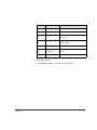
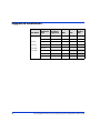
Supported emulations
OPEN
Emulation
Type
OPEN
Emulation
Supported
LUSE
CVS
LUSE &
CVS
OPEN-3
Yes
Yes
Yes
Yes
OPEN-8
Yes
Yes
Yes
Yes
XP128
OPEN-9
Yes
Yes
Yes
Yes
XP1024
OPEN-E
Yes
Yes
Yes
Yes
XP10000
OPEN-K
XP12000
OPEN-L
Yes
Yes
Yes
Yes
XP Model
OPEN-M
OPEN-V
64
HP StorageWorks Disk Array XP Operating System Configuration Guide: HP-UX
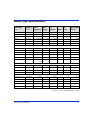
Device type specifications
Device Type
(Note 1)
Category
(Note 2)
Blocks
(512 bytes )
Sector
Size
(bytes)
# of
Cylinders
Heads
Sectors
per
Track
Capacity MB*
(Note 3)
OPEN-3
SCSI disk
4806720
512
3338
15
96
2347
OPEN-8
SCSI disk
14351040
512
9966
15
96
7007
OPEN-9
SCSI disk
14423040
512
10016
15
96
7042
OPEN-E
SCSI disk
28452960
512
19759
15
96
13893
OPEN-L
SCSI disk
71192160
512
49439
15
96
34761
OPEN-V
SCSI disk
max=125827200
512
Note 5
15
128
Note 6
OPEN-3*n
SCSI disk
4806720*n
512
3338*n
15
96
2347*n
OPEN-8*n
SCSI disk
14351040*n
512
9966*n
15
96
7007*n
OPEN-9*n
SCSI disk
14423040*n
512
10016*n
15
96
7042*n
OPEN-E*n
SCSI disk
28452960*n
512
19759*n
15
96
13893*n
OPEN-L*n
SCSI disk
71192160*n
512
49439*n
15
96
34761*n
OPEN-V*n
SCSI disk
max=125827200
Note 4
512
Note 5
15
128
Note 6
OPEN-3 CVS
SCSI disk
Note 4
512
Note 5
15
96
Note 6
OPEN-8 CVS
SCSI disk
Note 4
512
Note 5
15
96
Note 6
OPEN-9 CVS
SCSI disk
Note 4
512
Note 5
15
96
Note 6
OPEN-E CVS
SCSI disk
Note 4
512
Note 5
15
96
Note 6
OPEN-3*n CVS
SCSI disk
Note 4
512
Note 5
15
96
Note 6
OPEN-8*n CVS
SCSI disk
Note 4
512
Note 5
15
96
Note 6
OPEN-9*n CVS
SCSI disk
Note 4
512
Note 5
15
96
Note 6
OPEN-E*n CVS
SCSI disk
Note 4
512
Note 5
15
96
Note 6
OPEN-V*n
SCSI disk
Note 4
512
Note 5
15
128
Note 6
LUSE
CVS
CVS LUSE
*Capacity = (512 x number of blocks) ÷ 10242
Disk array device emulations
65
Note 1:
The availability of a disk type depends on the disk array.
Note 2:
The devices are defined to the host as SCSI disk devices, even though the
interface is Fibre Channel.
Note 3:
The device capacity can sometimes be changed by the BIOS or host adapter
board. This may make actual capacity different from that listed in the table.
Note 4:
The number of blocks for a CVS volume is calculated as follows:
# of blocks = (# of cylinders) × (# of heads) × (# of sectors per track)
Example 1: For an OPEN-3 CVS volume with capacity = 37 MB:
# of blocks = (53 cylinders–see Note 5) × (15 heads) × (96 sectors per
track) = 76320
Example 2: For an OPEN-V CVS volume with capacity = 49 MB:
# of blocks = (53 cylinders–see Note 5) × (15 heads) × (128 sectors per
track) = 101760
Note 5:
The number of cylinders for a CVS volume is calculated as follows (↑…↑
means that the value should be rounded up to the next integer):
OPEN-3/8/9/E: The number of cylinders for a CVS volume =
# of cylinders = ↑ (capacity (MB) specified by user) × 1024/720 ↑
Example: For an OPEN-3 CVS volume with capacity = 37 MB:
# of cylinders = ↑37 × 1024/720↑ = ↑52.62↑ (rounded up to next integer) =
53 cylinders
OPEN-V: The number of cylinders for a CVS volume =
# of cylinders = ↑ (capacity (MB) specified by user) × 16/15 ↑
Example: For an OPEN-V CVS volume with capacity = 49 MB:
# of cylinders = ↑49 × 16/15↑ = ↑52.26↑ (rounded up to next integer) = 53
cylinders
OPEN-3/8/9/E: The number of cylinders for a CVS LUSE volume =
# of cylinders = ↑ (capacity (MB) specified by user) × 1024/720 ↑ × n
66
HP StorageWorks Disk Array XP Operating System Configuration Guide: HP-UX
Example: For a CVS LUSE volume with capacity = 37 MB and n = 4
# of cylinders = ↑37 × 1024/720↑ × 4 = ↑52.62↑× 4 = 53 × 4 = 212
OPEN-V: The number of cylinders for a CVS LUSE volume =
# of cylinders = ↑ (capacity (MB) specified by user) × 16/15 ↑ × n
Example: For an OPEN-V CVS LUSE volume with capacity = 49 MB and
n=4
# of cylinders = ↑49 × 16/15↑ × 4 = ↑52.26↑× 4 = 53 × 4 = 212
Note 6:
Disk array device emulations
The capacity of an OPEN-3/8/9/E CVS volume is specified in MB, not
number of cylinders. The capacity of an OPEN-V CVS volume can be
specified in MB or number of cylinders. You set the volume size using the
Remote Web Console, Command View or Command View Advanced
Edition software.
67
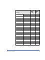
LUSE device parameters
Physical
extent
size (PE)
Max
physical
extent size
(MPE)
OPEN-K/3/8/9/E
OPEN-3/K*n (n= 2 to 36)
OPEN-3/K-CVS
OPEN-3/K*n-CVS (n = 2 to 36)
default
default
OPEN-8/9*n
n = 2 to 17
default
default
n = 18
8
15845
n = 19
8
16725
n = 20
8
17606
n = 21
8
18486
n = 22
8
19366
n = 23
8
20247
n = 24
8
21127
n = 25
8
22007
n = 26
8
22888
n = 27
8
23768
n = 28
8
24648
n = 29
8
25529
n = 30
8
26409
n = 31
8
27289
n = 32
8
28170
n = 33
8
29050
n = 34
8
29930
n = 35
8
30810
n = 36
8
31691
Device type
68
HP StorageWorks Disk Array XP Operating System Configuration Guide: HP-UX
Physical
extent
size (PE)
Max
physical
extent size
(MPE)
n = 2 to 9
default
default
n = 10
8
17366
n = 11
8
19102
n = 12
8
20839
n = 13
8
22576
n = 14
8
24312
n = 15
8
26049
n = 16
8
27786
n = 17
8
29522
n = 18
8
31259
n = 19
8
32995
n = 20
8
34732
n = 21
8
36469
n = 22
8
38205
n = 23
8
39942
n = 24
8
41679
n = 25
8
43415
n = 26
8
45152
n = 27
8
46889
n = 28
8
48625
n = 29
8
50362
n = 30
8
52098
n = 31
8
53835
n = 32
8
55572
Device type
OPEN-E*n
Disk array device emulations
69
Physical
extent
size (PE)
Max
physical
extent size
(MPE)
n = 33
8
57308
n = 34
8
59045
n = 35
8
60782
n = 36
8
62518
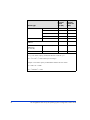
n = 2 to 3
default
default
default
default
70 to 119731(MB) × N1
8
default
119732 to (MB) × N1
8
N2
Device type
OPEN-L*n
OPEN-8/9/E-CVS
OPEN-V
OPEN-8/9/E*n-CVS
OPEN-V*n
(n = 2 to 36)
N1 = [ VCS volume capacity (in MB) from Remote Console PC ] × n
N2 = ↑ N1 / PE ↑ (↑ means round up to next integer)
Example: CVS volume capacity is 6000 MB for OPEN-9*22-CVS volume:
N1 = 6000 × 22 = 132000
N2 = ↑ 132000/8 ↑ = 16500
70
HP StorageWorks Disk Array XP Operating System Configuration Guide: HP-UX
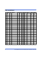
SCSI TID map for Fibre Channel adapters
When an arbitrated loop (AL) is established or reestablished, the port
addresses are assigned automatically to prevent duplicate TIDs. With the
SCSI over Fibre Channel protocol (FCP), there is no longer a need for
target IDs in the traditional sense.
SCSI is a bus-oriented protocol requiring each device to have a unique
address since all commands go to all devices. For Fibre Channel, the
AL-PA is used instead of the TID to direct packets to the desired
destination.
Unlike traditional SCSI, when control of the loop is acquired, a
point-to-point connection is established from initiator to target. To enable
transparent use of FCP, the operating system maps a TID to each AL-PA.
The host maps SCSI protocol to Fibre Channel protocol and detects and
accesses Fibre Channel-connected devices using device files
(/dev/dsk/c*t*d* and /dev/rdsk/c*t*d*) in the same way as for
SCSI-connected devices. The device files for Fibre Channel-connected
devices are configured in a different way from SCSI-connected devices,
because Fibre Channel supports 126 addresses per path while SCSI
supports 16 TIDs per path.
The following table identifies the fixed mappings between the TID (drive)
values assigned by the operating system and the Fibre Channel native
addresses (AL_PA/SEL_ID) for Fibre Channel adapters. The controller
number (the dks value in /dev/dsk/dks*d*l*s*) depends on the server
configuration, and a different value is assigned per each column.
Disk array device emulations
71
The mapping cannot be done when these conditions exist:
• disk array devices and other types of devices are connected in the
same loop
• information for unused devices remains in the server system
• multiple ports participate in the same arbitrated loop
ALPA
t
ALvalue PA
t
ALvalue PA
t
ALvalue PA
t
ALvalue PA
t
ALvalue PA
t
ALvalue PA
t
ALvalue PA
t
value
EF
0
CD
0
B2
0
98
0
72
0
55
0
3A
0
25
0
E8
1
CC
1
B1
1
97
1
71
1
54
1
39
1
23
1
E4
2
CB
2
AE
2
90
2
6E
2
53
2
36
2
1F
2
E2
3
CA
3
AD
3
8F
3
6D
3
52
3
35
3
1E
3
E1
4
C9
4
AC
4
88
4
6C
4
51
4
34
4
1D
4
E0
5
C7
5
AB
5
84
5
6B
4
4E
5
33
5
1B
5
DC
6
C6
6
AA
6
82
6
6A
6
4D
6
32
6
18
6
DA
7
C5
7
A9
7
81
7
69
7
4C
7
31
7
17
7
D9
8
C3
8
A7
8
80
8
67
8
4B
8
2E
8
10
8
D6
9
BC
9
A6
9
7C
9
66
9
4A
9
2D
9
0F
9
D5
10
BA
10
A5
10
7A
10
65
10
49
10
2C
10
08
10
D4
11
B9
11
A3
11
79
11
63
11
47
11
2B
11
04
11
D3
12
B6
12
9F
12
76
12
5C
12
46
12
2A
12
02
12
D2
13
B5
13
9E
13
75
13
5A
13
45
13
29
13
01
13
D1
14
B4
14
9D
14
74
14
59
14
43
14
27
14
00
–
CE
15
B3
15
9B
15
73
15
56
15
3C
15
26
15
72
HP StorageWorks Disk Array XP Operating System Configuration Guide: HP-UX
C
Reference information for SAM
The HP System Administrator Manager (SAM) is used to perform HP-UX
system administration functions, including:
• setting up users and groups
• configuring the disks and file systems
• performing auditing and security activities
• editing the system kernel configuration
This appendix provides instructions for:
• using SAM to configure the disk devices
• using SAM to set the maximum number of volume groups
Reference information for SAM
73
Configuring the devices using SAM
The SAM Areas window displays the system administration functions and
allows you to select the desired function. The Disks and File Systems
function allows you to configure new disk devices for LVM operations.
To configure the newly installed SCSI disk devices:
1. Select Disks and File Systems, then select Disk Devices.
74
HP StorageWorks Disk Array XP Operating System Configuration Guide: HP-UX
2. Verify that the new disk array devices are displayed in the Disk Devices
window.
3. Select the device to configure, select the Actions menu, select Add, and
then select Using the Logical Volume Manager.
4. In the Add a Disk Using LVM window, select Create... or Extend a
Volume Group.
5. In the Create a Volume Group window, enter the name of the new or
existing volume group to assign the new device to, and then click OK
twice. The Add a Disk Using LVM window now displays the volume
group name.
6. Select Add New Logical Volume to open the Create New Logical
Volumes window.
7. In the Create New Logical Volumes window, enter the name, size in
megabytes, and mount directory for the new logical volume. Select
Add, and then click OK twice.
8. Repeat steps 3 through 7 for each new disk device on the disk array.
Reference information for SAM
75
Setting the maximum number of volume groups
using SAM
The HP-UX kernel specifies the maximum number of volume groups that
can be created. The default is 10. You may need to change this number to
accommodate new devices on the disk array. To change this number, use
the Kernel Configuration function.
To change the maximum number of volume groups:
1. Select the Kernel Configuration function, then select Configurable
Parameters.
2. In the Configurable Parameters window, select the maxvgs
parameter, select the Actions menu, and then select Modify
Configurable Parameter.
3. In the Modify Configurable Parameter window, enter the desired
maximum number of volume groups in the Formula/Value field, and
then click OK.
4. In the Configurable Parameters window, make sure that none of the
parameters are selected. Then select the Actions menu, and select
Create New Kernel.
5. When the configuration window opens, click Yes to create the new
kernel (or click No to return to the Configurable Parameters window.)
6. When the Reboot the System window opens, click OK to move the
new kernel into place and reboot the system.
76
HP StorageWorks Disk Array XP Operating System Configuration Guide: HP-UX
Glossary
AL
Arbitrated loop.
AL-PA
Arbitrated loop physical address.
array group
A group of 4 or 8 physical hard disk drives (HDDs) installed in an XP disk
array and assigned a common RAID level. RAID1 array groups are made
up of 4 HDDs (2D+2D). A RAID1 group is two 4 HDD array groups
concatenated together (4D+4D). RAID5 array groups are made up of 4 or 8
HDDs, depending on whether they are RAID5 3D+1P or RAID5 7D+1P,
respectively. All RAID6 array groups are made up of 8 HDDs (6D+2P).
BC
HP StorageWorks Business Copy XP. BC lets you maintain up to nine local
copies of logical volumes on the disk array.
CA
HP StorageWorks Continuous Access XP. CA lets you create and maintain
duplicate copies of local logical volumes on a remote disk array.
Command View
(CVXP)
HP StorageWorks Command View XP, a software product for managing XP
arrays. Command View runs on a Windows-based management workstation.
Command View XP
Advanced Edition
(CVXP AE)
HP StorageWorks Command View XP Advanced Edition, installs on the
user-provided Device Manager server and provides a browser-based
platform from which you can manage the XP family of disk arrays—even
globally distributed arrays.
command device
A volume on the disk array that accepts Continuous Access or Business Copy
control operations which are then executed by the disk array.
CU
Control Unit. Contains LDEVs and is approximately equivalent to SCSI
Target ID.
Glossary
77
CVS
Custom volume size. CVS devices (OPEN-x CVS) are custom volumes
configured using array management software to be smaller than normal
fixed-size OPEN system volumes. Synonymous with volume size
customization (VSC).
DKC
(disk controller unit)
The array cabinet that houses the channel adapters and service processor
(SVP).
DKU
(disk cabinet unit)
The array cabinets that house the disk array physical disks.
emulation modes
The logical devices (LDEVs) associated with each RAID group are assigned
an emulation mode that makes them operate like OPEN system disk drives.
The emulation mode determines the size of an LDEV:
OPEN-3: 2.46 GB
OPEN-8: 7.38 GB
OPEN-9: 7.42 GB
OPEN-E: 13.56 GB
OPEN-L: 36 GB
OPEN-V: User-defined custom size
failover
Disconnecting a failed unit or path and replacing it with an alternative unit
or path in order to continue functioning.
FC
Fibre Channel.
FC-AL
Fibre Channel arbitrated loop.
FCP
Fibre Channel Protocol.
GB
Gigabytes
HBA
Host bus adapter.
host mode
Each port can be configured for a particular host type. These modes are
represented as two-digit hexadecimal numbers. For example, host mode 08
represents an HP-UX host.
78
HP StorageWorks Disk Array XP Operating System Configuration Guide: HP-UX
LDEV
Logical device. An LDEV is created when a RAID group is carved into pieces
according to the selected host emulation mode (that is, OPEN-3, OPEN-8,
OPEN-L). The number of resulting LDEVs depends on the selected
emulation mode. The term LDEV is often used synonymously with the term
volume.
LUN
Logical unit number. A LUN results from mapping a SCSI logical unit
number, port ID, and LDEV ID to a RAID group. The size of the LUN is
determined by the emulation mode of the LDEV and the number of LDEVs
associated with the LUN. For example, a LUN associated with two OPEN3 LDEVs has a size of 4,693 MB.
LUSE
A LUN is normally associated with only a single LDEV. The LUSE feature
allows a LUN to be associated with 1 to 36 LDEVs. Essentially, LUSE makes
it possible for applications to access a single large pool of storage. The LUSE
feature is available when the HP StorageWorks LUN Configuration Manager
product is installed.
OFC
Open Fibre Control.
OPEN-x
A general term describing any one of the supported OPEN emulation
modes (for example, OPEN-L).
OS
Operating system.
PA
Physical address.
path
“Path” and “LUN” are synonymous. Paths are created by associating a port,
a target, and a LUN ID with one or more LDEVs.
port
A physical connection that allows data to pass between a host and the disk
array. The number of ports on an XP disk array depends on the number of
supported I/O slots and the number of ports available per I/O adapter. The
XP family of disk arrays supports Fibre Channel (FC) ports as well as other
port types. Ports are named by port group and port letter, such as CL1-A.
CL1 is the group, and A is the port letter.
RAID
Redundant array of independent disks.
remote console PC
The PC running HP StorageWorks Remote Control XP.
Glossary
79
Remote Control (RC)
HP StorageWorks Remote Control XP. A software product used for
managing XP arrays.
Remote Web Console
(RWC)
HP StorageWorks XP Remote Web Console. A browser-based program
installed on the SVP that allows you to configure and manage the disk array.
R-SIM
Remote service information message.
SCSI
Small computer system interface.
SIM
Service information message.
SNMP
Simple Network Management Protocol.
SVP
Service processor, which is the PC built into the disk controller. The SVP
provides a direct interface into the disk array. SVP use is reserved for HP
support representatives only.
TB
Terabyte.
TID
Target ID.
Volume
On the XP array, a volume is a uniquely identified virtual storage device
composed of a control unit (CU) component and a logical device (LDEV)
component separated by a colon. For example 00:00 and 01:00 are two
uniquely identified volumes; one is identified as CU = 00 and LDEV = 00,
and the other as CU = 01 and LDEV = 00; they are two unique separate virtual
storage devices within the XP array.
VSC
Volume size customization. Synonymous with CVS.
WWN
World Wide Name. A unique identifier assigned to a Fibre Channel device.
80
HP StorageWorks Disk Array XP Operating System Configuration Guide: HP-UX
Index
A
arbitrated-loop physical address 24
authorized resellers 8
Auto LUN XP 17
Auto Path XP 17
auto-mount parameters, setting 52
B
Business Copy XP 17, 19
C
Cache LUN XP 17
Cluster Extension XP 17
clustering 27, 28
command device(s)
designate at least one LDEV as a 19
RAID Manager 19
Command View 16, 19, 21, 24
Command View XP Advanced Edition 16, 19,
21, 24, 30
configuration
device 35
emulation types 18
recognition 32
using SAM 74
Fibre Channel ports 24
HBAs 26
Index
host 26
host mode, setting 21
I/O timeout parameter 49
mount directories, creating 50
port 24
System Option Mode 23
Continuous Access Extension XP 17
Continuous Access XP 17, 19
D
Data Exchange XP 17
device(s)
configuration 35
using SAM 74
emulations 18
files
creating 38
verifying 36
logical, not recognized by host 56
LUSE device parameters 68
recognition 32
specifications 65
type specifications 65
verifying 32
directories, mount 50
disk array(s)
connecting 29
81
device types 65
features 16
installation overview 20
not ready message 58
operating system versions 16
requirements 16
self reboot 58
server support 16
storage capacity 16
supported 7
times out 58
documentation
related 8
E
emulation(s)
device emulation types 18
supported 64
error conditions 56
F
fabric environment
parameter settings 25
port addresses 24
zoning 27, 28
failover 18
Fibre Channel
adapters, SCSI TID map 71
connection speed 17
parameter settings 25
ports, configuring 24
supported elements 17
topology example 25
file system(s)
cannot be created 57
for logical volumes 47
mounting 51
82
not mounted after rebooting 57
verifying 36, 51
G
glossary 77
H
HBA(s)
configuring 26
installation, verifying 31
host
configuration 26
doesn’t reboot properly after hard
shutdown 56
hangs up 58
logical devices not recognized 56
parity error 58
host bus adapters, see "HBAs"
host mode, setting 21
HP
service representative tasks 21
technical support 59
HP-UX, supported versions 16
I
I/O timeout parameter, setting 49
installation
connecting disk array 29
HBA, verifying 31
HP service representative tasks 21
overview 20
L
LDEV(s)
designate at least one as a command
device 19
logical volume(s)
auto-mount parameters 52
HP StorageWorks Disk Array XP Operating System Configuration Guide: HP-UX
cannot be created 57
creating 45
file systems 47, 51
LUN Configuration and Security Manager
XP 16, 21, 29, 30
LUN(s)
creating 29
mapping 29
security 27
LUSE device parameters 68
M
mount directories, creating 50
multi-cluster environment 27
O
operating system(s)
loading 26
LUN security for 28
multiple, fabric zoning for 28
supported versions of HP-UX 16
P
parity error 58
path(s)
defining 29
worksheet 62
Performance Advisor XP 17
physical volume(s)
cannot be created 57
creating 41
creating groups 42
port(s)
address 24
Fibre Channel 24
host mode, setting 21
Index
R
RAID Manager command devices 19
RAID Manager XP 17
Remote Web Console 16, 19, 21, 24
resellers, authorized 8
Resource Manager XP 17
S
SAM (HP System Administrator Manager)
configuring devices using 74
reference information 73
volume groups, setting maximum
number 76
SCSI disk, Fibre Channel interface and term
"SCSI disk" 17
SCSI TIP map 71
Secure Manager XP 28
security, LUN 27, 28
server support 16
SNMP configuration 19
software, optional 17
storage capacity 16
StorageWorks, supported arrays 7
system administrator, required knowledge 7
System Option Mode, setting 23
T
technical support 9, 59
topology, fabric 25
troubleshooting 55
error conditions 56
technical support 59
U
Unix, supported versions HP-UX 16
V
volume(s)
83
groups
cannot be created 57
creating 42
setting maximum number 76
logical
auto-mount parameters 52
cannot be created 57
creating 45
file systems 47, 51
physical
cannot be created 57
creating 41
creating groups 42
W
warranty 12
web site
HP storage 8
worksheet, path 62
X
XP family
optional software 17
storage capacity 16
Z
zoning, fabric 27, 28
84
HP StorageWorks Disk Array XP Operating System Configuration Guide: HP-UX