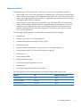
1
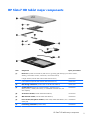
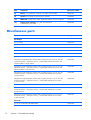
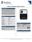
HP Slate10 HD and HP Slate7 HD
Maintenance and Service Guide
IMPORTANT! This document is intended for
HP authorized service providers only.
© Copyright 2013 Hewlett-Packard
Development Company, L.P.
Bluetooth is a trademark owned by its
proprietor and used by Hewlett-Packard
Company under license. SD Logo is a
trademark of its proprietor.
The information contained herein is subject
to change without notice. The only
warranties for HP products and services are
set forth in the express warranty statements
accompanying such products and services.
Nothing herein should be construed as
constituting an additional warranty. HP shall
not be liable for technical or editorial errors
or omissions contained herein.
First Edition: October 2013
Document Part Number: 741959-001
Product notice
This guide describes features that are
common to most models. Some features may
not be available on your computer.
Software terms
By installing, copying, downloading, or
otherwise using any software product
preinstalled on this tablet, you agree to be
bound by the terms of the HP End User
License Agreement (EULA). If you do not
accept these license terms, your sole remedy
is to return the entire unused product
(hardware and software) within 14 days for
a refund subject to the refund policy of your
place of purchase.
For any further information or to request a
full refund of the tablet, please contact your
local point of sale (the seller).
Safety warning notice
WARNING! To reduce the possibility of heat-related injuries or of overheating the device, do not
place the device directly on your lap or obstruct the device air vents. Use the device only on a hard, flat
surface. Do not allow another hard surface, such as an adjoining optional printer, or a soft surface,
such as pillows or rugs or clothing, to block airflow. Also, do not allow the AC adapter to contact
the skin or a soft surface, such as pillows or rugs or clothing, during operation. The device and the AC
adapter comply with the user-accessible surface temperature limits defined by the International
Standard for Safety of Information Technology Equipment (IEC 60950).
iii
iv
Safety warning notice
Table of contents
1 Product description ........................................................................................................... 1
2 External component identification ..................................................................................... 4
HP Slate10 HD ........................................................................................................................ 4
HP Slate7 HD .......................................................................................................................... 5
3 Illustrated parts catalog .................................................................................................... 6
Locating the serial number, product number, and model number .................................................... 6
HP Slate10 HD tablet major components ..................................................................................... 7
HP Slate7 HD tablet major components ....................................................................................... 9
Miscellaneous parts ................................................................................................................ 10
Sequential part number listing .................................................................................................. 11
4 Removal and replacement preliminary requirements ...................................................... 14
Tools required ........................................................................................................................ 14
Service considerations ............................................................................................................ 14
Plastic parts ............................................................................................................ 14
Cables and connectors ............................................................................................ 14
Grounding guidelines ............................................................................................................. 15
Electrostatic discharge damage ................................................................................. 15
Packaging and transporting guidelines ....................................................... 16
Workstation guidelines .............................................................. 16
5 Removal and replacement procedures ............................................................................ 18
Tablet component replacement procedures ................................................................................ 18
HP Slate10 HD ...................................................................................................................... 18
Back cover ............................................................................................................. 18
Sensor module ........................................................................................................ 19
Battery ................................................................................................................... 20
Power button board ................................................................................................. 22
Volume button board ............................................................................................... 23
v
Microphone ............................................................................................................ 24
Rear-facing webcamera ........................................................................................... 26
Audio board ........................................................................................................... 27
Card reader board .................................................................................................. 28
Speakers ................................................................................................................ 29
USB board ............................................................................................................. 30
System board ......................................................................................................... 32
Front-facing webcamera ........................................................................................... 35
HP Slate7 HD ........................................................................................................................ 37
Back cover ............................................................................................................. 37
Battery ................................................................................................................... 38
Rear-facing webcamera ........................................................................................... 39
Speakers ................................................................................................................ 40
USB board ............................................................................................................. 42
System board ......................................................................................................... 43
Antenna modules .................................................................................................... 46
Power button/microphone module ............................................................................. 47
Front-facing webcamera ........................................................................................... 49
6 Specifications ................................................................................................................. 51
HP Slate10 HD ...................................................................................................................... 51
HP Slate7 HD ........................................................................................................................ 52
7 Power cord set requirements .......................................................................................... 53
Requirements for all countries .................................................................................................. 53
Requirements for specific countries and regions ......................................................................... 53
8 Recycling ........................................................................................................................ 55
Index ................................................................................................................................. 56
vi
1
Product description
Category
Description
Product Name
HP Slate10 HD
HP Slate10 HD
x
HP Slate7 HD
x
Processor
Marvel® PXA986 1.20-GHz dual core soldered
on-chip (SOC) processor
x
Panel
10.0-in, (1280×800), a-Si, TFT, TouchScreen
display panel with liquid crystal display (LCD), 24bit color depth, 16:10 Ultra Wide Aspect Ratio;
WXGA: ≥ 75/75/75/75 viewing angle, singlelink low-voltage differential signalling (LVDS)
interface, traditional capacitive multi-touch
(>5 fingers)
x
7.0-in, (1280×800), a-Si, TFT, TouchScreen
display panel with liquid crystal display (LCD), 24bit color depth, 16:10 Ultra Wide Aspect Ratio;
WXGA: ≥ 75/75/75/75 viewing angle, singlelink low-voltage differential signalling (LVDS)
interface, traditional capacitive multi-touch
(>5 fingers)
HP Slate7 HD
x
x
1
Category
Description
Graphics
3D and 2d GPU
HP Slate10 HD
HP Slate7 HD
x
x
2D hardware acceleration include DirectFB and
alpha blending
Supports OpenGL ES 2.0/1.1 and OpenVG 1.1
Supports the following video decode formats:
●
1080p/30fps
●
720p/60fps
●
H.263
●
H.264
●
MPEG-4
●
MPEG 2
●
DivX
●
WMV
Supports the following video encode formats:
●
1080p/24fps
●
720p/30fps
●
H.263
●
H.264 BP
●
MPEG-4
Memory
Supports 1-GB DDR3 up to 1600-MHz
x
x
Mass storage
Supports a 16.0-GB embedded MultiMedia Card
(eMMC) solid-state drive v. 4..4.1
x
x
Audio and video
Integrated stereo speakers (2), 1.0-W per channel
x
x
x
x
One digital microphone
Support Beats Audio
5.0-MP, 1080p, autofocus rear-facing webcamera
2.0-MP, 720p front-facing webcamera
Sensors
Accelerometer
Ambient light sensor
e-Compass
Gyro position
Proximity
2
Chapter 1 Product description
Category
Description
Wireless networking
Integrated WiFi option: WiFi 802.11abgn;
Bluetooth and WiFi antenna support both 2.4G
and 5G bands
HP Slate10 HD
HP Slate7 HD
x
x
Integrated GPS option: Supports both A-GPS
and standalone GPS
Integrated Bluetooth option: Bluetooth
3.0+HS Class 2 (10m+ range)
Integrated WiDi option:
●
GSM–850/900/1800/1900
●
WCDMA–850/900/1700/1900/2100
External expansion
Integrated micro SD Card Reader expandable to
32-GB
x
x
Ports
Audio: 3.5-mm headphone/microphone combo
jack (supports North American-type headset only)
x
x
Micro USB 2.0 type AB connector (supports OTG
and charging)
Power requirements
Battery: supports a 3.7-V, 7000-mAh, 25.9WHr, Li-ion battery (non-removable), USB
charging battery
x
AC adapter: supports a 10-W AC adapter
with DC plug and localized cable plug support
Battery: supports a 3.7-V, 4000-mAh, 14.8WHr, Li-ion battery (non-removable), USB
charging battery
x
AC adapter: supports a 10-W AC adapter
with DC plug and localized cable plug support
Security
Software-based trusted platform module
(TPM) solution
x
x
Operating system
Preinstalled: Android 4.2
x
x
Serviceability
End user replaceable part: AC adapter
x
x
3
2
External component identification
HP Slate10 HD
4
Item
Component
Item
Component
(1)
Audio-out (headphone)/Audio-in
(microphone) jack
(6)
Volume control buttons (2)
(2)
Rear-facing webcamera
(7)
Speakers (2)
(3)
Microphone
(8)
Micro USB 2.0 port
(4)
Power button
(9)
Micro SIM slot
(5)
Front-facing webcamera
(10)
Micro SD Card Reader slot
Chapter 2 External component identification
HP Slate7 HD
Item
Component
Item
Component
(1)
Rear-facing webcamera
(6)
Speakers (2)
(2)
Microphone
(7)
Audio-out (headphone)/Audio-in
(microphone) jack
(3)
Power button
(8)
Micro USB 2.0 port
(4)
Front-facing webcamera
(9)
Micro SD Card Reader slot
(5)
Volume control buttons (2)
(10)
Micro SIM slot
HP Slate7 HD
5
3
Illustrated parts catalog
Locating the serial number, product number, and
model number
The serial number and product number of your tablet are located on the bottom edge of the tablet. You
may need this information when you travel internationally or when you contact support.
6
Chapter 3 Illustrated parts catalog
HP Slate10 HD tablet major components
Item
Component
Spare part number
(1)
Back cover (includes media card slot, power button actuator, SIM slot cover, speaker grilles, volume button
actuator, and webcamera lens)
For use only on tablet models equipped with WWAN capability in bright red finish
(includes WWAN antenna cable and transceivers)
748791-001
For use only on tablet models equipped with WWAN capability in silver slate finish
(includes WWAN antenna cable and transceivers)
748790-001
For use only on tablet models equipped with WiFi capability in bright red finish
(includes WiFi antenna cable and transceivers)
744532-001
For use only on tablet models equipped with WiFi capability in silver slate finish
(includes WiFi antenna cable and transceivers)
743082-001
(2)
Sensor module (includes double-sided adhesive)
744539-001
(3)
Power button board (includes cable, double-sided adhesive, and rubber pad)
744538-001
HP Slate10 HD tablet major components
7
8
Item
Component
Spare part number
(4)
Microphone (includes cable and double-sided adhesive)
744533-001
(5)
Rear-facing webcamera (includes cable and double-sided adhesive)
744545-001
(6)
Audio board (includes audio jack and bracket)
744537-001
(7)
Volume button board (includes cable, double-sided adhesive, and rubber pad)
744541-001
(8)
Card reader board (includes cable, micro SIM slot, and micro
SD Card Reader slot)
744540-001
(9)
System board equipped with a Marvel PXA986 1.20-GHz dual core (SOC) processor, 1.0-GB system memory,
and a 16-GB eMMC solid-state drive:
Equipped with WWAN capability
744058-001
Equipped with WiFi capability
744057-001
(10)
Battery, 3.7-V, 7000-mAh, 25.9-WHr, Li-ion (includes cable)
743896-001
(11)
Speakers (includes left and right speakers and cables)
744543-001
(12)
USB board (includes bracket, cable, micro USB port, and rubber pad)
744536-001
(13)
Front-facing webcamera (includes cable)
744544-001
(14)
Display panel assembly, 10.0-in, LCD, TFT, TouchScreen
(includes display panel cable)
743084-001
Chapter 3 Illustrated parts catalog
HP Slate7 HD tablet major components
Item
Component
Spare part number
(1)
Back cover (includes card reader slot, SIM slot cover, grounding pads and tape, power button actuator,
shielding, volume button actuator, webcam lens, and wireless antenna)
In bright red finish (includes WiFi antenna cable and transceivers)
744579-001
In silver slate finish (includes WiFi antenna cable and transceivers)
743041-001
(2)
Rear-facing webcamera (includes cable and double-sided adhesive)
743051-001
(3)
System board equipped with a Marvel PXA986 1.20-GHz dual core
(SOC) processor, 1.0-GB system memory, a 16-GB eMMC solid-state drive, and
WiFi capability
743049-001
(4)
3G antenna module (includes double-sided adhesive)
747947-001
(5)
WiFi antenna module (includes double-sided adhesive)
743045-001
(6)
Power button/microphone module (includes cable, double-sided adhesive, and
rubber pad)
744580-001
(7)
Front-facing webcamera (includes cable)
743050-001
HP Slate7 HD tablet major components
9
Item
Component
Spare part number
(8)
Battery, 3.7-V, 4000-mAh, 14.8-WHr, Li-ion battery (includes cable)
743895-001
(9)
Speakers (includes left and right speakers and cables)
743048-001
(10)
USB board (includes bracket, cable, double-sided adhesive, and micro USB port)
743044-001
(11)
Display panel assembly, 7.0-in, LCD, TFT, TouchScreen
(includes display panel cable)
743046-001
Miscellaneous parts
Component
Spare part number
AC adapter:
For use in Brazil
744423-012
For use in Europe and South Korea
744423-009
For use in MERCO
744423-001
For use in North America
744423-008
For use in the United Kingdom and Singapore
744423-003
HP Slate10 HD tablet:
Equipped with a Marvel PXA986 1.20-GHz dual core (SOC) processor, a 10.0-in, LCD, TFT,
TouchScreen display, 1.0-GB system memory, a 16-GB eMMC solid-state drive, WiFi, and
WWAN capability in bright red finish
744535-001
Equipped with a Marvel PXA986 1.20-GHz dual core (SOC) processor, a 10.0-in, LCD, TFT,
TouchScreen display, 1.0-GB system memory, a 16-GB eMMC solid-state drive, WiFi, and
WWAN capability in slate silver finish
744056-001
Equipped with a Marvel PXA986 1.20-GHz dual core (SOC) processor, a 10.0-in, LCD, TFT,
TouchScreen display, 1.0-GB system memory, a 16-GB eMMC solid-state drive, and WiFi
in bright red finish
744534-001
Equipped with a Marvel PXA986 1.20-GHz dual core (SOC) processor, a 10.0-in, LCD, TFT,
TouchScreen display, 1.0-GB system memory, a 16-GB eMMC solid-state drive, and WiFi
in slate silver finish
743083-001
HP Slate7 HD tablet:
Equipped with a Marvel PXA986 1.20-GHz dual core (SOC) processor, a 7.0-in, LCD, TFT,
TouchScreen display, 1.0-GB system memory, a 16-GB eMMC solid-state drive, and WiFi
in bright red finish
744581-001
Equipped with a Marvel PXA986 1.20-GHz dual core (SOC) processor, a 7.0-in, LCD, TFT,
TouchScreen display, 1.0-GB system memory, a 16-GB eMMC solid-state drive, and WiFi
in slate silver finish
743043-001
Screw Kit:
For use only on HP Slate10 HD tablet models
10
Chapter 3 Illustrated parts catalog
744542-001
Component
Spare part number
For use only on HP Slate7 HD tablet models
743047-001
USB extension cable
751600-001
Sequential part number listing
Spare part number
Description
743041-001
Back cover in silver slate finish for use only on HP Slate7 HD tablet models (includes card reader
slot, SIM slot cover, grounding pads and tape, power button actuator, shielding, volume button
actuator, webcam lens, and wireless antenna)
743043-001
HP Slate7 HD tablet equipped with a Marvel PXA986 1.20-GHz dual core (SOC) processor, a 7.0in, LCD, TFT, TouchScreen display, 1.0-GB system memory, a 16-GB eMMC solid-state drive, and
WiFi in silver slate finish
743044-001
USB board for use only on HP Slate7 HD tablet models (includes bracket, cable, double-sided
adhesive, and micro USB port)
743045-001
WiFi antenna module for use only on HP Slate7 HD tablet models (includes double-sided adhesive)
743046-001
7.0-in, LCD, TFT, TouchScreen display panel assembly for use only on HP Slate7 HD tablet models
(includes display panel cable)
743047-001
Screw Kit for use only on HP Slate7 HD tablet models
743048-001
Speaker Kit for use only on HP Slate7 HD tablet models
743049-001
System board equipped with a Marvel PXA986 1.20-GHz dual core (SOC) processor, 1.0-GB
system memory, a 16-GB eMMC solid-state drive, and WiFi for use only on HP Slate7 HD
tablet models
743050-001
Front-facing webcamera for use only on HP Slate7 HD tablet models (includes cable)
743051-001
Rear-facing webcamera for use only on HP Slate7 HD tablet models (includes cable and doublesided adhesive)
743082-001
Back cover in silver slate finish for use only on HP Slate10 HD tablet models equipped with WiFi
(includes media card slot, power button actuator, SIM slot cover, speaker grilles, volume button
actuator, and webcamera lens)
743083-001
HP Slate10 HD tablet equipped with a Marvel PXA986 1.20-GHz dual core (SOC) processor, a
10.0-in, LCD, TFT, TouchScreen display, 1.0-GB system memory, a 16-GB eMMC solid-state drive,
and WiFi in silver slate finish
743084-001
10.0-in, LCD, TFT, TouchScreen display panel assembly for use only on HP Slate10 HD tablet
models (includes display panel cable)
743895-001
Battery, 3.7-V, 4000-mAh, 14.8-WHr, Li-ion for use only on HP Slate7 HD tablet models
(includes cable)
743896-001
Battery, 3.7-V, 7000-mAh, 25.9-WHr, Li-ion for use only on HP Slate10 HD tablet models
(includes cable)
744056-001
HP Slate10 HD tablet equipped with a Marvel PXA986 1.20-GHz dual core (SOC) processor, a
10.0-in, LCD, TFT, TouchScreen display, 1.0-GB system memory, a 16-GB eMMC solid-state drive,
WiFi, and WWAN capability in silver slate finish
Sequential part number listing
11
12
Spare part number
Description
744057-001
System board equipped with a Marvel PXA986 1.20-GHz dual core (SOC) processor, 1.0-GB
system memory, a 16-GB eMMC solid-state drive, and WiFi for use only on
HP Slate10 HD tablet models
744058-001
System board equipped with a Marvel PXA986 1.20-GHz dual core (SOC) processor, 1.0-GB
system memory, a 16-GB eMMC solid-state drive, WiFi, and WWAN capability for use only on
HP Slate10 HD tablet models
744423-001
10-W USB duck-head AC adapter for use in MERCO
744423-003
10-W USB duck-head AC adapter for use in the United Kingdom and Singapore
744423-008
10-W USB duck-head AC adapter for use in North America
744423-009
10-W USB duck-head AC adapter for use in Europe and South Korea
744423-012
10-W USB duck-head AC adapter for use in Brazil
744532-001
Back cover in bright red finish for use only on HP Slate10 HD tablet models equipped with WiFi
(includes media card slot, power button actuator, SIM slot cover, speaker grilles, volume button
actuator, and webcamera lens)
744533-001
Microphone for use only on HP Slate10 HD tablet models (includes cable and doublesided adhesive)
744534-001
HP Slate10 HD tablet equipped with a Marvel PXA986 1.20-GHz dual core (SOC) processor, a
10.0-in, LCD, TFT, TouchScreen display, 1.0-GB system memory, a 16-GB eMMC solid-state drive,
and WiFi in bright red finish
744535-001
HP Slate10 HD tablet equipped with a Marvel PXA986 1.20-GHz dual core (SOC) processor, a
10.0-in, LCD, TFT, TouchScreen display, 1.0-GB system memory, a 16-GB eMMC solid-state drive,
WiFi, and WWAN capability in bright red finish
744536-001
USB board for use only on HP Slate10 HD tablet models (includes bracket, cable, micro USB port,
and rubber pad)
744537-001
Audio board for use only on HP Slate10 HD tablet models (includes audio jack and bracket)
744538-001
Power button board for use only on HP Slate10 HD tablet models (includes cable, double-sided
adhesive, and rubber pad)
744539-001
Sensor module for use only on HP Slate10 HD tablet models (includes double-sided adhesive)
744540-001
Card reader board for use only on HP Slate10 HD tablet models (includes cable, micro SIM slot,
and micro SD Card Reader slot)
744541-001
Volume button board for use only on HP Slate10 HD tablet models (includes cable, double-sided
adhesive, and rubber pad)
744542-001
Screw Kit for use only on HP Slate10 HD tablet models
744543-001
Speaker Kit for use only on HP Slate10 HD tablet models (includes left and right speakers
and cables)
744544-001
Front-facing webcamera for use only on HP Slate10 HD tablet models (includes cable and doublesided adhesive)
744545-001
Rear-facing webcamera for use only on HP Slate10 HD tablet models (includes cable)
744579-001
Back cover in bright red finish for use only on HP Slate7 HD tablet models (includes card reader
slot, SIM slot cover, grounding pads and tape, power button actuator, shielding, volume button
actuator, webcam lens, and wireless antenna)
Chapter 3 Illustrated parts catalog
Spare part number
Description
744580-001
Power button/microphone module for use only on HP Slate7 HD tablet models (includes cable,
double-sided adhesive, and rubber pad)
744581-001
HP Slate7 HD tablet equipped with a Marvel PXA986 1.20-GHz dual core (SOC) processor, a 7.0in, LCD, TFT, TouchScreen display, 1.0-GB system memory, a 16-GB eMMC solid-state drive, and
WiFi in bright red finish
747947-001
3G antenna module for use only on HP Slate7 HD tablet models (includes double-sided adhesive)
748790-001
Back cover in silver slate finish for use only on HP Slate10 HD tablet models equipped with
WWAN capability (includes media card slot, power button actuator, SIM slot cover, speaker
grilles, volume button actuator, and webcamera lens)
748791-001
Back cover in bright red finish for use only on HP Slate10 HD tablet models equipped with WWAN
capability (includes media card slot, power button actuator, SIM slot cover, speaker grilles, volume
button actuator, and webcamera lens)
751600-001
USB extension cable
Sequential part number listing
13
4
Removal and replacement
preliminary requirements
Tools required
You will need the following tools to complete the removal and replacement procedures:
●
Magnetic screw driver
●
Phillips P0 screw driver
●
Plastic case utility tool
Service considerations
The following sections include some of the considerations that you must keep in mind during
disassembly and assembly procedures.
NOTE: As you remove each subassembly from the tablet, place the subassembly (and all
accompanying screws) away from the work area to prevent damage.
Plastic parts
CAUTION: Using excessive force during disassembly and reassembly can damage plastic parts.
Use care when handling the plastic parts. Apply pressure only at the points designated in the
maintenance instructions.
Cables and connectors
CAUTION: When servicing the tablet, be sure that cables are placed in their proper locations during
the reassembly process. Improper cable placement can damage the tablet.
Cables must be handled with extreme care to avoid damage. Apply only the tension required to unseat
or seat the cables during removal and insertion. Handle cables by the connector whenever possible. In
all cases, avoid bending, twisting, or tearing cables. Be sure that cables are routed in such a way that
they cannot be caught or snagged by parts being removed or replaced. Handle flex cables with
extreme care; these cables tear easily.
14
Chapter 4 Removal and replacement preliminary requirements
Grounding guidelines
Electrostatic discharge damage
Electronic components are sensitive to electrostatic discharge (ESD). Circuitry design and structure
determine the degree of sensitivity. Networks built into many integrated circuits provide some
protection, but in many cases, ESD contains enough power to alter device parameters or melt
silicon junctions.
A discharge of static electricity from a finger or other conductor can destroy static-sensitive devices or
microcircuitry. Even if the spark is neither felt nor heard, damage may have occurred.
An electronic device exposed to ESD may not be affected at all and can work perfectly throughout a
normal cycle. Or the device may function normally for a while, then degrade in the internal layers,
reducing its life expectancy.
CAUTION: To prevent damage to the tablet when you are removing or installing internal
components, observe these precautions:
Keep components in their electrostatic-safe containers until you are ready to install them.
Before touching an electronic component, discharge static electricity by using the guidelines described
in this section.
Avoid touching pins, leads, and circuitry. Handle electronic components as little as possible.
If you remove a component, place it in an electrostatic-safe container.
The following table shows how humidity affects the electrostatic voltage levels generated by
different activities.
CAUTION: A product can be degraded by as little as 700 V.
Typical electrostatic voltage levels
Relative humidity
Event
10%
40%
55%
Walking across carpet
35,000 V
15,000 V
7,500 V
Walking across vinyl floor
12,000 V
5,000 V
3,000 V
Motions of bench worker
6,000 V
800 V
400 V
Removing DIPS from plastic tube
2,000 V
700 V
400 V
Removing DIPS from vinyl tray
11,500 V
4,000 V
2,000 V
Removing DIPS from Styrofoam
14,500 V
5,000 V
3,500 V
Removing bubble pack from PCB
26,500 V
20,000 V
7,000 V
Packing PCBs in foam-lined box
21,000 V
11,000 V
5,000 V
Grounding guidelines
15
Packaging and transporting guidelines
Follow these grounding guidelines when packaging and transporting equipment:
●
To avoid hand contact, transport products in static-safe tubes, bags, or boxes.
●
Protect ESD-sensitive parts and assemblies with conductive or approved containers or packaging.
●
Keep ESD-sensitive parts in their containers until the parts arrive at static-free workstations.
●
Place items on a grounded surface before removing items from their containers.
●
Always be properly grounded when touching a component or assembly.
●
Store reusable ESD-sensitive parts from assemblies in protective packaging or
nonconductive foam.
●
Use transporters and conveyors made of antistatic belts and roller bushings. Be sure that
mechanized equipment used for moving materials is wired to ground and that proper materials
are selected to avoid static charging. When grounding is not possible, use an ionizer to dissipate
electric charges.
Workstation guidelines
Follow these grounding workstation guidelines:
16
●
Cover the workstation with approved static-shielding material.
●
Use a wrist strap connected to a properly grounded work surface and use properly grounded tools
and equipment.
●
Use conductive field service tools, such as cutters, screw drivers, and vacuums.
●
When fixtures must directly contact dissipative surfaces, use fixtures made only of staticsafe materials.
●
Keep the work area free of nonconductive materials, such as ordinary plastic assembly aids
and Styrofoam.
●
Handle ESD-sensitive components, parts, and assemblies by the case or PCM laminate. Handle
these items only at static-free workstations.
●
Avoid contact with pins, leads, or circuitry.
●
Turn off power and input signals before inserting or removing connectors or test equipment.
Chapter 4 Removal and replacement preliminary requirements
Equipment guidelines
Grounding equipment must include either a wrist strap or a foot strap at a grounded workstation.
●
When seated, wear a wrist strap connected to a grounded system. Wrist straps are flexible straps
with a minimum of one megohm ±10% resistance in the ground cords. To provide proper ground,
wear a strap snugly against the skin at all times. On grounded mats with banana-plug connectors,
use alligator clips to connect a wrist strap.
●
When standing, use foot straps and a grounded floor mat. Foot straps (heel, toe, or boot straps)
can be used at standing workstations and are compatible with most types of shoes or boots. On
conductive floors or dissipative floor mats, use foot straps on both feet with a minimum of one
megohm resistance between the operator and ground. To be effective, the conductive must be
worn in contact with the skin.
The following grounding equipment is recommended to prevent electrostatic damage:
●
Antistatic tape
●
Antistatic smocks, aprons, and sleeve protectors
●
Conductive bins and other assembly or soldering aids
●
Nonconductive foam
●
Conductive tabletop workstations with ground cords of one megohm resistance
●
Static-dissipative tables or floor mats with hard ties to the ground
●
Field service kits
●
Static awareness labels
●
Material-handling packages
●
Nonconductive plastic bags, tubes, or boxes
●
Metal tote boxes
●
Electrostatic voltage levels and protective materials
The following table lists the shielding protection provided by antistatic bags and floor mats.
Material
Use
Voltage protection level
Antistatic plastics
Bags
1,500 V
Carbon-loaded plastic
Floor mats
7,500 V
Metallized laminate
Floor mats
5,000 V
Grounding guidelines
17
5
Removal and replacement
procedures
Tablet component replacement procedures
CAUTION: Tablet components described in this chapter should only be accessed by an authorized
service provider. Accessing these parts can damage the tablet and void the warranty.
This chapter provides removal and replacement procedures for authorized service provider only parts.
HP Slate10 HD
There are as many as 22 screws that must be removed, replaced, and/or loosened when servicing
the HP Slate10 HD tablet. Make special note of each screw size and location during removal
and replacement.
Back cover
Description
Spare part number
Back cover (includes media card slot, power button actuator, SIM slot cover, speaker grilles, volume button actuator, and
webcamera lens)
For use only on tablet models equipped with WWAN capability in bright red finish (includes
WWAN antenna cable and transceivers)
748791-001
For use only on tablet models equipped with WWAN capability in silver slate finish (includes
WWAN antenna cable and transceivers)
748790-001
Display panel assembly, 10.0-in, LCD, TFT, TouchScreen (includes display panel cable)
743084-001
Before disassembling the HP Slate10 HD, follow these steps:
18
1.
Turn off the tablet. If you are unsure whether the tablet is off or in Hibernation, turn the tablet on,
and then shut it down through the operating system.
2.
Disconnect the power from the tablet by unplugging the power cord from the tablet.
3.
Disconnect all external devices from the tablet.
Chapter 5 Removal and replacement procedures
Remove the back cover:
1.
Place the tablet on a flat surface, display panel side up, with the speakers and the micro USB port
toward you.
2.
Insert a case utility tool (1) or similar thin, plastic tool between the back cover and the display
panel assembly. The first insertion point should be in the top edge of the tablet near the
audio jack (2).
3.
Lift the top edge of the back cover (3) until it separates from the display panel assembly.
4.
Lift the left (4) and the right sides (5) of the back cover until they detach from the
display panel assembly.
5.
Remove the back cover (6).
Reverse this procedure to install the back cover.
Sensor module
Description
Spare part number
Sensor module
744539-001
Before removing the sensor module, follow these steps:
1.
Turn off the tablet. If you are unsure whether the tablet is off or in Hibernation, turn the tablet on,
and then shut it down through the operating system.
2.
Disconnect the power from the tablet by unplugging the power cord from the tablet.
3.
Disconnect all external devices from the tablet.
4.
Remove the back cover (see Back cover on page 18).
HP Slate10 HD
19
Remove the sensor module:
1.
Turn the back cover upside down with the bottom edge toward you.
2.
Detach the sensor module (1) from the back cover. (The sensor module is attached to the back
cover with double-sided adhesive.)
3.
Remove the sensor module (2).
Reverse this procedure to install the sensor module.
Battery
Description
Spare part number
Battery, 3.7-V, 7000-mAh, 25.9-WHr, LI (includes cable)
743896-001
Before removing the battery, follow these steps:
1.
Turn off the tablet. If you are unsure whether the tablet is off or in Hibernation, turn the tablet on,
and then shut it down through the operating system.
2.
Disconnect the power from the tablet by unplugging the power cord from the tablet.
3.
Disconnect all external devices from the tablet.
4.
Remove the back cover (see Back cover on page 18).
WARNING! To reduce potential safety issues, use only the battery provided with the tablet, a
replacement battery provided by HP, or a compatible battery purchased from HP.
20
Chapter 5 Removal and replacement procedures
CAUTION: Removing a battery that is the sole power source for the tablet can cause loss of
information. To prevent loss of information, save your work or shut down the tablet through Windows
before removing the battery.
Remove the battery:
CAUTION: Before turning the display panel assembly upside down, make sure the work surface is
clear of tools, screws, and any other foreign objects. Failure to follow this caution can result in damage
to the display panel assembly.
1.
Place the tablet on a flat surface, display panel side down, with the speakers and the micro USB
port toward you.
2.
Disconnect the battery cable (1) from the system board.
3.
Remove the rubber pads (2) that protect the mini-USB board zero insertion force (ZIF) connector
and the display panel cable ZIF connector.
4.
Release the ZIF connector (3) to which the mini-USB board cable is attached, and then disconnect
the mini-USB board cable from the system board.
5.
Release the ZIF connector (4) to which the display panel cable is attached, and then disconnect
the display panel cable from the system board.
6.
Detach the mini-USB board cable (5) and the display panel cable from the battery. (The mini-USB
board cable and the display panel cable are attached to the battery with double-sided adhesive.)
HP Slate10 HD
21
7.
Remove the six Phillips PM2.0×2.75 screws (1) that secure the battery to the
display panel assembly.
8.
Lift the top edge of the battery (2) and swing it up and back to release it.
9.
Remove the battery (3).
Reverse this procedure to install the battery.
Power button board
Description
Spare part number
Power button board (includes cable, double-sided adhesive, and rubber pad)
744538-001
Before removing the power button board, follow these steps:
22
1.
Turn off the tablet. If you are unsure whether the tablet is off or in Hibernation, turn the tablet on,
and then shut it down through the operating system.
2.
Disconnect the power from the tablet by unplugging the power cord from the tablet.
3.
Disconnect all external devices from the tablet.
4.
Remove the back cover (see Back cover on page 18).
5.
Disconnect the battery cable from the system board (see Battery on page 20).
Chapter 5 Removal and replacement procedures
Remove the power button board:
1.
Remove the rubber pad (1) that protects the power button board cable ZIF connector.
2.
Release the ZIF connector (2) to which the power button board cable is attached, and then
disconnect the power button board cable from the system board.
3.
Detach the power button board (3) from the display panel assembly. (The power button board is
attached to the display panel assembly with double-sided adhesive.)
4.
Remove the power button board and cable.
Reverse this procedure to install the power button board and cable.
Volume button board
Description
Spare part number
Volume button board (includes cable, double-sided adhesive, and rubber pad)
744541-001
Before removing the volume button board, follow these steps:
1.
Turn off the tablet. If you are unsure whether the tablet is off or in Hibernation, turn the tablet on,
and then shut it down through the operating system.
2.
Disconnect the power from the tablet by unplugging the power cord from the tablet.
3.
Disconnect all external devices from the tablet.
HP Slate10 HD
23
4.
Remove the back cover (see Back cover on page 18).
5.
Disconnect the battery cable from the system board (see Battery on page 20).
Remove the volume button board:
1.
Remove the rubber pad (1) that protects the volume button board cable ZIF connector.
2.
Release the ZIF connector (2) to which the volume button board cable is attached, and then
disconnect the volume button board cable from the system board.
3.
Detach the volume button board (3) from the display panel assembly. (The volume button board is
attached to the display panel assembly with double-sided adhesive.)
4.
Remove the volume button board and cable.
Reverse this procedure to install the volume button board.
Microphone
Description
Spare part number
Microphone (includes cable)
744533-001
Before removing the microphone, follow these steps:
24
1.
Turn off the tablet. If you are unsure whether the tablet is off or in Hibernation, turn the tablet on,
and then shut it down through the operating system.
2.
Disconnect the power from the tablet by unplugging the power cord from the tablet.
Chapter 5 Removal and replacement procedures
3.
Disconnect all external devices from the tablet.
4.
Remove the back cover (see Back cover on page 18).
5.
Disconnect the battery cable from the system board (see Battery on page 20).
Remove the microphone:
1.
Release the ZIF connector (1) to which the microphone cable is attached, and then disconnect the
microphone cable from the system board.
2.
Detach the microphone (2) from the display panel assembly. (The microphone is attached to the
display panel assembly with double-sided adhesive.)
3.
Remove the microphone and cable.
Reverse this procedure to install the microphone.
HP Slate10 HD
25
Rear-facing webcamera
Description
Spare part number
Rear-facing webcamera (includes cable)
744545-001
Before removing the rear-facing webcamera, follow these steps:
1.
Turn off the tablet. If you are unsure whether the tablet is off or in Hibernation, turn the tablet on,
and then shut it down through the operating system.
2.
Disconnect the power from the tablet by unplugging the power cord from the tablet.
3.
Disconnect all external devices from the tablet.
4.
Remove the back cover (see Back cover on page 18).
5.
Disconnect the battery cable from the system board (see Battery on page 20).
Remove the rear-facing webcamera:
1.
Disconnect the rear-facing webcamera cable (1) from the system board.
2.
Detach the rear-facing webcamera (2) from the display panel assembly. (The rear-facing
webcamera is attached to the display panel assembly with double-sided adhesive.)
3.
Remove the rear-facing webcamera and cable.
Reverse this procedure to install the rear-facing webcamera.
26
Chapter 5 Removal and replacement procedures
Audio board
Description
Spare part number
Audio board (includes audio jack and bracket)
744537-001
Before removing the audio board, follow these steps:
1.
Turn off the tablet. If you are unsure whether the tablet is off or in Hibernation, turn the tablet on,
and then shut it down through the operating system.
2.
Disconnect the power from the tablet by unplugging the power cord from the tablet.
3.
Disconnect all external devices from the tablet.
4.
Remove the back cover (see Back cover on page 18).
5.
Disconnect the battery cable from the system board (see Battery on page 20).
Remove the audio board:
1.
Release the ZIF connector (1) to which the card reader board cable is attached, and then
disconnect the card reader board cable from the audio board.
2.
Remove the two Phillips PM2.0×2.75 screws (2) that secure the audio board and bracket to the
display panel assembly.
3.
Remove the audio board bracket (3) and the audio board (4).
HP Slate10 HD
27
Reverse this procedure to install the audio board.
Card reader board
Description
Spare part number
Card reader board (includes cable, micro SIM slot, and micro SD Card Reader slot)
744540-001
Before removing the card reader board, follow these steps:
1.
Turn off the tablet. If you are unsure whether the tablet is off or in Hibernation, turn the tablet on,
and then shut it down through the operating system.
2.
Disconnect the power from the tablet by unplugging the power cord from the tablet.
3.
Disconnect all external devices from the tablet.
4.
Remove the back cover (see Back cover on page 18).
5.
Disconnect the battery cable from the system board (see Battery on page 20).
Remove the audio board:
28
1.
Release the ZIF connector (1) to which the card reader board cable is attached, and then
disconnect the card reader board cable from the audio board.
2.
Release the ZIF connector (2) to which the card reader board cable is attached, and then
disconnect the card reader board cable from the system board.
3.
Remove the two Phillips PM2.0×2.75 screws (3) that secure the card reader board to the
display panel assembly.
Chapter 5 Removal and replacement procedures
4.
Remove the card reader board (4).
Reverse this procedure to install the card reader board.
Speakers
Description
Spare part number
Speaker Kit (includes left and right speakers and cables)
744543-001
Before removing the speakers, follow these steps:
1.
Turn off the tablet. If you are unsure whether the tablet is off or in Hibernation, turn the tablet on,
and then shut it down through the operating system.
2.
Disconnect the power from the tablet by unplugging the power cord from the tablet.
3.
Disconnect all external devices from the tablet.
4.
Remove the back cover (see Back cover on page 18).
5.
Disconnect the battery cable from the system board (see Battery on page 20).
Remove the speakers:
1.
Disconnect the speaker cables (1) from the system board.
2.
Release the speaker cables from the retention clips (2) and channels built into the
display panel assembly.
HP Slate10 HD
29
3.
Remove the four Phillips PM2.0×2.75 screws (3) that secure the speakers to the
display panel assembly.
4.
Remove the speakers (4).
Reverse this procedure to install the speakers.
USB board
Description
Spare part number
USB board (includes bracket, cable, micro USB port, and rubber pad)
744536-001
Before removing the USB board, follow these steps:
30
1.
Turn off the tablet. If you are unsure whether the tablet is off or in Hibernation, turn the tablet on,
and then shut it down through the operating system.
2.
Disconnect the power from the tablet by unplugging the power cord from the tablet.
3.
Disconnect all external devices from the tablet.
4.
Remove the back cover (see Back cover on page 18).
5.
Disconnect the battery cable from the system board (see Battery on page 20).
Chapter 5 Removal and replacement procedures
Remove the USB board:
1.
Remove the rubber pad (1) that protects the USB board cable ZIF connector.
2.
Release the ZIF connector (2) to which the USB board cable is attached, and then disconnect the
USB board cable from the system board.
3.
Detach the USB board cable (3) from the display panel assembly. (The USB board cable is
attached to the display panel assembly with double-sided adhesive.)
4.
Remove the two Phillips PM2.0×2.0 broad head screws (4) that secure the USB board to the
display panel assembly.
5.
Remove the USB board bracket (5) and the USB board (6).
Reverse this procedure to install the USB board.
HP Slate10 HD
31
System board
NOTE: The system board spare part kit is equipped with a Marvel PXA986 1.20-GHz dual core
(SOC) processor, 1.0-GB system memory, and a 16-GB eMMC solid-state drive.
Description
Spare part number
Equipped with WWAN capability
744058-001
Equipped with WiFi capability
744057-001
Before removing the system board, follow these steps:
32
1.
Turn off the tablet. If you are unsure whether the tablet is off or in Hibernation, turn the tablet on,
and then shut it down through the operating system.
2.
Disconnect the power from the tablet by unplugging the power cord from the tablet.
3.
Disconnect all external devices from the tablet.
4.
Remove the back cover (see Back cover on page 18).
5.
Disconnect the battery cable from the system board (see Battery on page 20).
Chapter 5 Removal and replacement procedures
Remove the system board:
1.
Disconnect the following cables from the system board:
(1) Left speaker cable
(2) Power button board ZIF connector and cable
(3) Volume button board ZIF connector and cable
(4) TouchScreen module ZIF connector and cable
(5) USB board ZIF connector and cable
(6) Display panel cable ZIF connector and cable
HP Slate10 HD
33
2.
Disconnect the following cables from the system board:
(1) Microphone ZIF connector and cable
(2) Rear-facing webcamera cable
(3) Card reader board ZIF connector and cable
(4) Right speaker cable
3.
34
Remove the three Phillips PM2.0×2.75 screws (1) and the three Phillips PM2.0×2.0 broad head
screws (2) that secure the system board to the display panel assembly.
Chapter 5 Removal and replacement procedures
4.
Remove the system board (3).
Reverse this procedure to install the system board.
Front-facing webcamera
Description
Spare part number
Front-facing webcamera (includes cable)
744544-001
Before removing the front-facing webcamera, follow these steps:
1.
Turn off the tablet. If you are unsure whether the tablet is off or in Hibernation, turn the tablet on,
and then shut it down through the operating system.
2.
Disconnect the power from the tablet by unplugging the power cord from the tablet.
3.
Disconnect all external devices from the tablet.
4.
Remove the back cover (see Back cover on page 18).
5.
Disconnect the battery cable from the system board (see Battery on page 20).
6.
Remove the system board (see System board on page 32).
HP Slate10 HD
35
Remove the front-facing webcamera:
1.
Turn the system board upside down, with the bottom edge toward you.
2.
Release the ZIF connector (1) to which the front-facing webcamera cable is attached, and then
disconnect the front-facing webcamera cable from the system board.
3.
Remove the front-facing webcamera (2) and cable.
Reverse this procedure to install the front-facing webcamera.
36
Chapter 5 Removal and replacement procedures
HP Slate7 HD
There are as many as 16 screws that must be removed, replaced, and/or loosened when servicing
the HP Slate7 HD tablet. Make special note of each screw size and location during removal
and replacement.
Back cover
Description
Spare part number
Back cover (includes card reader slot, SIM slot cover, grounding pads and tape, power button actuator, shielding, volume
button actuator, webcam lens, and wireless antenna)
In bright red finish (includes WiFi antenna cable and transceivers)
744579-001
In silver slate finish (includes WiFi antenna cable and transceivers)
743041-001
Display panel assembly, 7.0-in, LCD, TFT, TouchScreen (includes display panel cable)
743046-001
Before disassembling the HP Slate7 HD tablet, follow these steps:
1.
Turn off the tablet. If you are unsure whether the tablet is off or in Hibernation, turn the tablet on,
and then shut it down through the operating system.
2.
Disconnect the power from the tablet by unplugging the power cord from the tablet.
3.
Disconnect all external devices from the tablet.
Remove the back cover:
1.
Place the tablet on a flat surface, display panel side up, with the micro SD Card Reader slot and
micro SIM slot toward you.
2.
Insert a case utility tool (1) or similar thin, plastic tool between the back cover and the display
panel assembly. The first insertion point should be in the left side of the tablet near the micro SD
Card Reader slot (2).
3.
Lift the left side of the back cover (3) until it separates from the display panel assembly.
4.
Lift the top (4) and the bottom edges (5) of the back cover until they detach from the
display panel assembly.
HP Slate7 HD
37
5.
Remove the back cover (6).
Reverse this procedure to install the back cover.
Battery
Description
Spare part number
Battery, 3.7-V, 4000-mAh, 14.8-WHr, Li-ion (includes cable)
743895-001
Before removing the battery, follow these steps:
1.
Turn off the tablet. If you are unsure whether the tablet is off or in Hibernation, turn the tablet on,
and then shut it down through the operating system.
2.
Disconnect the power from the tablet by unplugging the power cord from the tablet.
3.
Disconnect all external devices from the tablet.
4.
Remove the back cover (see Back cover on page 37).
WARNING! To reduce potential safety issues, use only the battery provided with the tablet, a
replacement battery provided by HP, or a compatible battery purchased from HP.
CAUTION: Removing a battery that is the sole power source for the tablet can cause loss of
information. To prevent loss of information, save your work or shut down the tablet through Windows
before removing the battery.
Remove the battery:
CAUTION: Before turning the display panel assembly upside down, make sure the work surface is
clear of tools, screws, and any other foreign objects. Failure to follow this caution can result in damage
to the display panel assembly.
38
1.
Place the tablet on a flat surface, display panel side down, with the volume control buttons
toward you.
2.
Disconnect the battery cable (1) from the system board.
Chapter 5 Removal and replacement procedures
3.
Release the tape (2) that secures the TouchScreen cable to the battery.
4.
Release the speaker cables from the retention clips (3) built into the battery.
5.
Remove the three Phillips PM2.0×2.75 screws (4) that secure the battery to the
display panel assembly.
6.
Remove the battery (5).
Reverse this procedure to install the battery.
Rear-facing webcamera
Description
Spare part number
Rear-facing webcamera (includes cable and double-sided adhesive)
743051-001
Before removing the rear-facing webcamera, follow these steps:
1.
Turn off the tablet. If you are unsure whether the tablet is off or in Hibernation, turn the tablet on,
and then shut it down through the operating system.
2.
Disconnect the power from the tablet by unplugging the power cord from the tablet.
3.
Disconnect all external devices from the tablet.
HP Slate7 HD
39
4.
Remove the back cover (see Back cover on page 37).
5.
Disconnect the battery cable from the system board (see Battery on page 38).
Remove the rear-facing webcamera:
1.
Disconnect the rear-facing webcamera cable (1) from the system board.
2.
Detach the rear-facing webcamera (2) from the display panel assembly. (The rear-facing
webcamera is attached to the display panel assembly with double-sided adhesive.)
3.
Remove the rear-facing webcamera and cable.
Reverse this procedure to install the rear-facing webcamera.
Speakers
Description
Spare part number
Speaker Kit (includes left and right speakers and cables)
743048-001
Before removing the speakers, follow these steps:
40
1.
Turn off the tablet. If you are unsure whether the tablet is off or in Hibernation, turn the tablet on,
and then shut it down through the operating system.
2.
Disconnect the power from the tablet by unplugging the power cord from the tablet.
3.
Disconnect all external devices from the tablet.
Chapter 5 Removal and replacement procedures
4.
Remove the back cover (see Back cover on page 37).
5.
Disconnect the battery cable from the system board (see Battery on page 38).
Remove the speakers:
1.
Disconnect the speaker cable (1) from the system board.
2.
Release the ZIF connector (2) to which the TouchScreen module cable is attached, and then
disconnect the TouchScreen module cable from the system board.
3.
Detach the TouchScreen module cable (3) from the battery. (The TouchScreen module cable is
attached to the battery with double-sided adhesive.)
4.
Remove the four Phillips PM2.0×2.75 screws (4) that secure the speakers to the
display panel assembly.
5.
Remove the speakers (5).
Reverse this procedure to install the speakers.
HP Slate7 HD
41
USB board
Description
Spare part number
USB board (includes bracket, cable, double-sided adhesive, and micro USB port)
743044-001
Before removing the USB board, follow these steps:
1.
Turn off the tablet. If you are unsure whether the tablet is off or in Hibernation, turn the tablet on,
and then shut it down through the operating system.
2.
Disconnect the power from the tablet by unplugging the power cord from the tablet.
3.
Disconnect all external devices from the tablet.
4.
Remove the back cover (see Back cover on page 37).
5.
Disconnect the battery cable from the system board (see Battery on page 38).
Remove the USB board:
1.
Release the ZIF connector (1) to which the USB board cable is attached, and then disconnect the
USB board cable from the system board.
2.
Remove the USB board bracket (2).
3.
Detach the USB board (3) from the display panel assembly. (The USB board is attached to the
display panel assembly with double-sided adhesive.)
4.
Remove the USB board and cable.
Reverse this procedure to install the USB board.
42
Chapter 5 Removal and replacement procedures
System board
Description
Spare part number
Equipped with a Marvel PXA986 1.20-GHz dual core (SOC) processor, 1.0-GB system memory, a
16-GB eMMC solid-state drive, and WiFi capability
743049-001
Before removing the system board, follow these steps:
1.
Turn off the tablet. If you are unsure whether the tablet is off or in Hibernation, turn the tablet on,
and then shut it down through the operating system.
2.
Disconnect the power from the tablet by unplugging the power cord from the tablet.
3.
Disconnect all external devices from the tablet.
4.
Remove the back cover (see Back cover on page 37).
5.
Disconnect the battery cable from the system board (see Battery on page 38).
HP Slate7 HD
43
Remove the system board:
1.
Disconnect the following cables from the system board:
(1) Rear-facing webcamera cable
(2) Front-facing webcamera cable
(3) Power button/microphone module cable
(4) Volume button board cable
(5) Display panel cable ZIF connector and cable
44
Chapter 5 Removal and replacement procedures
2.
Disconnect the following cables from the system board:
(1) USB board ZIF connector and cable
(2) Speaker cable
(3) TouchScreen module cable
3.
Remove the following screws that secure the system board to the display panel assembly:
(1) One Phillips PM1.4×4.1 screw
(2) Two Phillips PM2.0×3.5 screws
(3) Three Phillips PM2.0×2.75 screws
HP Slate7 HD
45
4.
Remove the system board (4).
Reverse this procedure to install the system board.
Antenna modules
Description
Spare part number
3G antenna module
747947-001
WiFi antenna module
743045-001
Before removing the antenna modules, follow these steps:
46
1.
Turn off the tablet. If you are unsure whether the tablet is off or in Hibernation, turn the tablet on,
and then shut it down through the operating system.
2.
Disconnect the power from the tablet by unplugging the power cord from the tablet.
3.
Disconnect all external devices from the tablet.
4.
Remove the back cover (see Back cover on page 37).
5.
Remove the battery (see Battery on page 38).
6.
Remove the system board (see System board on page 43).
Chapter 5 Removal and replacement procedures
Remove the antenna modules:
1.
Remove the three Phillips PM2.0×2.75 screws (1) that secure the antenna modules to the
display panel assembly.
2.
Detach the 3G antenna module (2) from the display panel assembly. (The 3G antenna module is
attached to the display panel assembly with double-sided adhesive.)
3.
Detach the WiFi antenna module (3) from the display panel assembly. (The WiFi antenna module
is attached to the display panel assembly with double-sided adhesive.)
4.
Remove the antenna modules.
Reverse this procedure to install the antenna modules.
Power button/microphone module
Description
Spare part number
Power button/microphone module (includes cable, double-sided adhesive, and rubber pad)
744580-001
Before removing the power button/microphone module, follow these steps:
1.
Turn off the tablet. If you are unsure whether the tablet is off or in Hibernation, turn the tablet on,
and then shut it down through the operating system.
2.
Disconnect the power from the tablet by unplugging the power cord from the tablet.
HP Slate7 HD
47
3.
Disconnect all external devices from the tablet.
4.
Remove the back cover (see Back cover on page 37), and then remove the following components:
a.
Battery (see Battery on page 38)
b.
System board (see System board on page 43)
c.
3G antenna module (see Antenna modules on page 46)
Remove the power button/microphone module:
48
1.
Turn the 3G antenna module upside down with the bottom toward you.
2.
Detach the power button/microphone module from the rear surface of the 3G antenna module.
(The power button/microphone module is attached to the 3G antenna module with doublesided adhesive.)
3.
Turn the 3G antenna module right side up with the bottom toward you.
Chapter 5 Removal and replacement procedures
4.
Detach the power button/microphone module base plate from the 3G antenna module. (The
power button/microphone module is attached to the 3G antenna module with doublesided adhesive.)
5.
Remove the power button/microphone module and cable.
Reverse this procedure to install the power button/microphone module.
Front-facing webcamera
Description
Spare part number
Front-facing webcamera (includes cable)
743050-001
Before removing the front-facing webcamera, follow these steps:
1.
Turn off the tablet. If you are unsure whether the tablet is off or in Hibernation, turn the tablet on,
and then shut it down through the operating system.
2.
Disconnect the power from the tablet by unplugging the power cord from the tablet.
HP Slate7 HD
49
3.
Disconnect all external devices from the tablet.
4.
Remove the back cover (see Back cover on page 37), and then remove the following components:
a.
Battery (see Battery on page 38)
b.
System board (see System board on page 43)
c.
3G antenna module (see Antenna modules on page 46)
Remove the front-facing webcamera:
1.
Turn the 3G antenna module upside down with the bottom toward you.
2.
Release the front-facing webcamera from the retention molding built into the 3G antenna module.
3.
Remove the front-facing webcamera and cable.
Reverse this procedure to install the front-facing webcamera.
50
Chapter 5 Removal and replacement procedures
6
Specifications
HP Slate10 HD
Metric
U.S.
Width
17.80 cm
7.01 in
Depth
0.97 cm
0.38 in
Height
25.90 cm
10.19 in
Weight (lowest weight configuration)
0.63 kg
1.38 lb
Dimensions
Input power
The tablet operates on DC power, which can be supplied by an AC or a DC power source. The AC power source must be
rated at 100—240 V, 50/60 Hz.
NOTE: The tablet can operate on DC power using an industry-standard micro-A or micro-B USB cable. The HP 5V 2A
adapter included with your tablet is recommended for charging the tablet.
Temperature
Operating
5°C to 35°C
41°F to 95°F
Nonoperating
-20°C to 60°C
-4°F to 140°F
Relative humidity (non-condensing)
Operating
10% to 90%
Nonoperating
5% to 95%
Maximum altitude (unpressurized)
Operating
-15 m to 3,048 m
-50 ft to 10,000 ft
Nonoperating
-15 m to 12,192 m
-50 ft to 40,000 ft
NOTE: Applicable product safety standards specify thermal limits for plastic surfaces. The device operates well within this
range of temperatures.
HP Slate10 HD
51
HP Slate7 HD
Metric
U.S.
Width
20.13 cm
7.93 in
Depth
0.99 cm
0.39 in
Height
11.98 cm
4.72 in
Weight
0.33 kg
0.72 lb
Dimensions
Input power
The tablet operates on DC power, which can be supplied by an AC or a DC power source. The AC power source must be
rated at 100—240 V, 50/60 Hz.
NOTE: The tablet can operate on DC power using an industry-standard micro-A or micro-B USB cable. The HP 5V 2A
adapter included with your tablet is recommended for charging the tablet.
Temperature
Operating
5°C to 35°C
41°F to 95°F
Nonoperating
-20°C to 60°C
-4°F to 140°F
Relative humidity (non-condensing)
Operating
10% to 90%
Nonoperating
5% to 95%
Maximum altitude (unpressurized)
Operating
-15 m to 3,048 m
-50 ft to 10,000 ft
Nonoperating
-15 m to 12,192 m
-50 ft to 40,000 ft
NOTE: Applicable product safety standards specify thermal limits for plastic surfaces. The device operates well within this
range of temperatures.
52
Chapter 6 Specifications
7
Power cord set requirements
The wide-range input feature of the tablet permits it to operate from any line voltage from 100 to 120
volts AC, or from 220 to 240 volts AC.
The 3-conductor power cord set included with the tablet meets the requirements for use in the country or
region where the equipment is purchased.
Power cord sets for use in other countries and regions must meet the requirements of the country or
region where the tablet is used.
Requirements for all countries
The following requirements are applicable to all countries and regions:
●
The length of the power cord set must be at least 1.0 m (3.3 ft) and no more than 2.0 m (6.5 ft).
●
All power cord sets must be approved by an acceptable accredited agency responsible for
evaluation in the country or region where the power cord set will be used.
●
The power cord sets must have a minimum current capacity of 10 amps and a nominal voltage
rating of 125 or 250 V AC, as required by the power system of each country or region.
●
The appliance coupler must meet the mechanical configuration of an EN 60 320/IEC 320
Standard Sheet C13 connector for mating with the appliance inlet on the back of the tablet.
Requirements for specific countries and regions
Country/region
Accredited agency
Applicable note number
Australia
EANSW
1
Austria
OVE
1
Belgium
CEBC
1
Canada
CSA
2
Denmark
DEMKO
1
Finland
FIMKO
1
France
UTE
1
Requirements for all countries
53
54
Country/region
Accredited agency
Applicable note number
Germany
VDE
1
Italy
IMQ
1
Japan
METI
3
The Netherlands
KEMA
1
Norway
NEMKO
1
The People's Republic of China
COC
5
South Korea
EK
4
Sweden
CEMKO
1
Switzerland
SEV
1
Taiwan
BSMI
4
The United Kingdom
BSI
1
The United States
UL
2
1.
The flexible cord must be Type HO5VV-F, 3-conductor, 1.0-mm² conductor size. Power cord set fittings (appliance coupler
and wall plug) must bear the certification mark of the agency responsible for evaluation in the country or region where it
will be used.
2.
The flexible cord must be Type SPT-3 or equivalent, No. 18 AWG, 3-conductor. The wall plug must be a two-pole
grounding type with a NEMA 5-15P (15 A, 125 V) or NEMA 6-15P (15 A, 250 V) configuration.
3.
The appliance coupler, flexible cord, and wall plug must bear a “T” mark and registration number in accordance with the
Japanese Dentori Law. The flexible cord must be Type VCT or VCTF, 3-conductor, 1.00-mm² conductor size. The wall plug
must be a two-pole grounding type with a Japanese Industrial Standard C8303 (7 A, 125 V) configuration.
4.
The flexible cord must be Type RVV, 3-conductor, 0.75-mm² conductor size. Power cord set fittings (appliance coupler
and wall plug) must bear the certification mark of the agency responsible for evaluation in the country or region where it
will be used.
5.
The flexible cord must be Type VCTF, 3-conductor, 0.75-mm² conductor size. Power cord set fittings (appliance coupler
and wall plug) must bear the certification mark of the agency responsible for evaluation in the country or region where it
will be used.
Chapter 7 Power cord set requirements
8
Recycling
When a non-rechargeable or rechargeable battery has reached the end of its useful life, do not dispose
of the battery in general household waste. Follow the local laws and regulations in your area for
battery disposal.
HP encourages customers to recycle used electronic hardware, HP original print cartridges, and
rechargeable batteries. For more information about recycling programs, see the HP Web site at
http://www.hp.com/recycle.
55
Index
Symbols/Numerics
3G antenna module
removal 46
spare part number 9, 13, 46
A
AC adapter, spare part numbers
10, 12
antenna
removal 46
spare part numbers 9, 11, 13,
46
audio board
removal 27
spare part number 8, 12, 27
audio, product description 2
audio-in jack 4, 5
audio-out jack 4, 5
B
back cover
removal 18, 37
spare part numbers 7, 9, 11,
12, 13, 18, 37
battery
removal 20, 38
spare part numbers 8, 10, 11,
20, 38
buttons
power 4, 5
volume control 4, 5
C
cables, service considerations 14
card reader board
removal 28
spare part number 8, 12, 28
Card Reader slot 4, 5
56
Index
connectors, service
considerations 14
D
display panel assembly, spare part
numbers 8, 10, 11, 18, 37
display panel, product
description 1
E
electrostatic discharge 15
equipment guidelines 17
external expansion, product
description 3
F
front-facing webcamera
location 4, 5
removal 35, 49
spare part numbers 8, 9, 11,
12, 35, 49
G
graphics, product description 2
grounding guidelines 15
guidelines
equipment 17
grounding 15
packaging 16
transporting 16
workstation 16
H
headphone jack 4, 5
J
jacks
audio-in 4, 5
audio-out 4, 5
headphone 4, 5
microphone 4, 5
M
mass storage device, product
description 2
memory module, product
description 2
microphone
location 4, 5
product description 2
removal 24
spare part number 8, 12, 24
microphone jack 4, 5
model name 1
O
operating system, product
description 3
P
packaging guidelines 16
plastic parts, service
considerations 14
ports
product description 3
USB 2.0 4, 5
power button 4, 5
power button board
removal 22
spare part number 7, 12, 22
power button/microphone module
removal 47
spare part number 9, 13, 47
power cord, set requirements 53
power requirements, product
description 3
processor, product description 1
product description
audio 2
display panel 1
external expansion 3
graphics 2
mass storage 2
memory module 2
microphone 2
operating system 3
ports 3
power requirements 3
processors 1
product name 1
security 3
sensor 2
serviceability 3
video 2
wireless networking 3
product name 1
R
rear-facing webcamera
location 4, 5
removal 26, 39
spare part numbers 8, 9, 11,
12, 26, 39
S
Screw Kit, spare part numbers
10, 11, 12
security, product description 3
sensor module
removal 19
spare part number 7, 12, 19
sensor, product description 2
service considerations
cables 14
connectors 14
plastic parts 14
serviceability, product description
3
SIM slot 4, 5
Speaker Kit, spare part numbers
8, 10, 11, 12, 29, 40
speakers
location 4, 5
removal 29, 40
spare part numbers 8, 10, 11,
12, 29, 40
system board
removal 32, 43
spare part numbers 8, 9, 11,
12, 32, 43
T
tablet
major components 7, 9
spare part numbers 10, 11,
12, 13
specifications 51, 52
tools required 14
transporting guidelines 16
U
USB 2.0 port 4, 5
USB board
removal 30, 42
spare part numbers 8, 10, 11,
12, 30, 42
USB extension cable, spare part
number 11, 13
V
video, product description 2
volume button board
removal 23
spare part number 8, 12, 23
volume control buttons 4, 5
W
webcamera
removal 26, 35, 39, 49
spare part numbers 8, 9, 11,
12, 26, 35, 39, 49
WiFi antenna module
removal 46
spare part number 9, 11, 46
wireless networking, product
description 3
workstation guidelines 16
Index
57