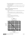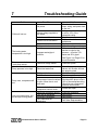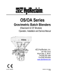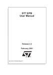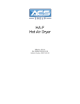
1
PS-025 QuarterHorse Series 0.25 hp Portable Chiller Operation and Installation Manual AEC, Inc./Application Engineering is committed to a continuing program of product improvement. Specifications, appearance, and dimensions described in this manual are subject to change without notice. © Copyright AEC/Application Engineering and AEC, Inc. 2002 All rights reserved. Effective 9/24/02 Page 2 PS QuarterHorse Series Chillers Safety Considerations PS Series Chillers are designed to provide safe and reliable operation when installed and operated within design specifications, following national and local safety codes. To avoid possible personnel injury or equipment damage when installing, operating or maintaining this equipment, use good judgment and follow these safe practices: ; Follow all SAFETY CODES. ; Wear SAFETY GLASSES and WORK GLOVES. ; Use care when LOADING, UNLOADING, RIGGING, or MOVING this equipment. ; Operate this equipment within design specifications. ; OPEN, TAG, and LOCK ALL DISCONNECTS before working on equipment. It is a good idea to remove the fuses and carry them with you. ; Make sure the chiller is properly GROUNDED before switching power on. ; When welding or brazing in or around this equipment, be sure VENTILATION is ADEQUATE. PROTECT adjacent materials from flame or sparks by shielding with sheet metal. An approved FIRE EXTINGUISHER should be close at hand and ready for use if needed. ; The refrigeration system can develop refrigerant pressures in excess of 500 psi (3,450 kPa). DO NOT CUT into the system without first relieving pressure. ; Do not jump or bypass any electrical safety control. ; Do not restore power until all tools, test equipment etc. have been removed and the panels replaced. ; Only PROPERLY TRAINED personnel familiar with the information within this manual should work on this equipment. PS QuarterHorse Series Chillers Page 3 Table of Contents 1 General Information ................................................. 7 1-1 1-2 1-3 1-4 1-5 1-6 1-7 1-8 1-9 2 Chiller Installation................................................... 11 2-1 2-2 2-3 2-4 2-5 3 Electrical Connections Process Water Connections PS Condenser Air Supply Water Reservoir Overhead Process Considerations Sequence of Operation .......................................... 15 3-1 3-2 Page 4 Introduction Necessary Documents Models Covered Available Options Uncrating Your New Chiller In the Event of Shipping Damages If the Shipment is Not Complete If the Shipment is Incorrect Returns Chilled Water Circuit Refrigeration Circuit PS QuarterHorse Series Chillers Table of Contents 4 Startup Checklists .................................................. 17 4-1 4-2 4-3 5 Microprocessor Control......................................... 19 5-1 5-2 5-3 6 Introduction Setting the Process Water Temperature Power Switch Routine Maintenance ............................................. 21 6-1 6-2 7 Introduction PS Pre-Startup Checklist PS Startup Checklist Lubrication Condenser Maintenance Troubleshooting Guide .......................................... 23 PS QuarterHorse Series Chillers Page 5 Charts and Figures 1 2 3 4 Page 6 PS050A Process Pump Curves 10 PS Series Chiller Specifications 10 Ethylene Glycol Curve 13 Overhead Piping 14 PS QuarterHorse Series Chillers 1 1-1 General Information Introduction PS Series Water Chillers are reliable, accurate, and easy-to-use air cooled chillers designed for use with water/glycol. Standard range of operation is 50°F to 70°F (10°C to 21°C). This PS chiller is a ¼ hp (187 W) model and has an internal one gallon (3.8 liter) reservoir. It is self contained, fully assembled, and shipped ready to use. A properly installed, operated, and maintained PS Series Chiller will provide many years of reliable operation. To get the most satisfaction from your new chiller, read and follow the instructions in this manual. 1-2 Necessary Documents The following documents are necessary for the operation, installation and maintenance PS Series Chillers. Additional copies are available from Application Engineering. Familiarize the appropriate personnel with these documents: ; This manual. ; The electrical schematic and connection diagram. ; The operation and installation manuals for installed accessories and options. 1-3 Models Covered This manual provides operation, installation, and maintenance instructions for PS-025 QuarterHorse Series chillers. Model numbers are on the serial tag. Please know the model number, serial number and operating voltage of your chiller if you need to contact Application Engineering. The PS QuarterHorse Series chiller model is designated by approximate compressor horsepower. An PS025 chiller has a ¼ hp (187 W) compressor. PS QuarterHorse Series Chillers Page 7 1-4 Available Options PS Series chillers are available with options that tailor the unit to your requirements. Some are factory installed, some can be retrofitted in the field. Consult your local Application Engineering Sales Representative. Some of these options are: Power Cord A 6 foot (1.8 m) power cord is available to speed PS installation. Feet Four leveling feet are mounted to the base of the PS unit. 1-5 Uncrating Your New Chiller PS Series chillers are shipped mounted on a skid, enclosed in a plastic wrapper, and open crated on all four sides and top. ; Pry the crating away from the skid and remove. Use a pry bar to remove the blocks securing the unit to the skid. ; Lift the unit off the skid with a fork truck. Insert forks between skid and chiller from the side until they protrude beyond the opposite side of the unit. The forks must be equidistant from the center line of the unit and the unit must be balanced on the forks. ; Lift slowly and only high enough to clear the skid. Use a pry bar if necessary to remove the skid from the unit. ; Lower slowly. The unit will land on its feet or casters and can be moved into position. Page 8 PS QuarterHorse Series Chillers 1-6 In the Event of Shipping Damages Important! According to the contract terms and conditions of the Carrier, the responsibility of the Shipper ends at the time and place of shipment. ; Notify the transportation company’s local agent. ; Hold the damaged goods and packing material for the examining agent’s inspection. Do not return any goods to Application Engineering before the transportation company's inspection and authorization. ; File a claim against the transportation company. Substantiate the claim by referring to the agent’s report. A certified copy of our invoice is available upon request. The original Bill of Lading is attached to our original invoice. If the shipment was prepaid, write us for a receipted transportation bill. 1-7 If the Shipment is Not Complete Check the packing list. The apparent shortage may be intentional. Back-ordered items are noted on the packing list. You should have: ; ; ; ; PS Series Chiller Bill of Lading Packing list Operating and Installation packet Re-inspect the container and packing material to see if smaller items have been missed during unpacking. Determine that the item was not taken from the area before the shipment was checked in. Notify Application Engineering immediately of the shortage. 1-8 If the Shipment is Incorrect ; If the shipment is not what you ordered, contact Application Engineering immediately. Include the order number and item. ; Hold the items until shipping instructions are received. PS QuarterHorse Series Chillers Page 9 1-9 Returns Important! Do not return any damaged or incorrect items until you receive shipping instructions from Application Engineering. Figure 1 PS025 Process Pump Curve PS025 - PROCES S PUMP S SELECTION TOTAL HEAD MTRS PSI FEET 49 69 160 37 52 120 24 35 80 12 18 40 U. S. GALLONS PER MINUTE LITRES PER MINUTE 60 HERTZ PUMP CURVE 0.4 0.8 1.2 1.6 2.0 2.4 2.8 3.2 3.6 4.0 4.4 4.8 1.5 3.0 4.5 6.1 7.6 9.1 10. 6 12. 1 13. 6 15. 1 16. 7 18. 2 CURVES REPRESENT PUMP DISCHARG E ADJUSTED FOR INTERNAL BY-P ASS Do not extrapolate pump curves. Figure 2 PS Series Chiller Specifications PS Cap. @ Quarter- 65°F lwt, Nominal Horse 90°F chilled Series ambient water Compressor PS-025 BTUH gpm hp American standards 2,213 2 ¼ PS Cap. @ Quarter- 18°C lwt, Nominal Horse 24°C chilled Series ambient water Compressor PS-025 watts lpm watts Metric standards Page 10 64.8 7.6 187 Pump 1/3 hp, 2 gpm @ 50 psig Pump 224 watts, 7.6 lpm @ 345 kPa Amp Process draw Dimensions connection 230/1/60 inches inches NPT running L W H ½ 6.7 A 20 26 34 Amp Process draw Dimensions connection 230/1/60 cm inches NPT running L W H ½ 6.7 A 48 32 66 Oper. weight lbs. Ship. weight lbs. 100 100 Oper. weight kg Ship. weight kg 46 46 PS QuarterHorse Series Chillers 2 2-1 Chiller Installation Electrical Connections Check serial tag voltage and amperage requirements and make sure your electrical service conforms. See Figure 2 on Page 10 for total running amps. ; Electrical connections must comply with all applicable electrical codes. ; The chiller must be grounded in accordance with NEC Article 250. ; Voltage must be within 10% of the chiller’s nameplate rating. 2-2 Process Water Connections ; All external chilled water connections to the process must be of adequate size. ; See Figure 4 on Page 14 for sizing recommendations. ; The largest possible openings and passages should be provided for the flow of chilled water through platens, dies, molds or other pieces of equipment. Important! Keep any pressure drop in external process piping to an absolute minimum for optimum unit operation. To Process Connect the TO PROCESS chilled water supply outlet to the process being cooled. From Process Connect the FROM PROCESS chilled water return inlet to the return from the process back into the chiller for cooling and recirculation. ; This chiller model has a strainer on the FROM PROCESS return line. PS QuarterHorse Series Chillers Page 11 Process Water Bypass All PS chillers have an internal bypass device. If the process flow becomes blocked during chiller operation, this component allows water to flow through the chiller. This protects the chiller from freeze-up, excessive pressures, and pump damage, and allows other safety features to remain effective. 2-3 PS Condenser Air Supply PS chillers use the surrounding air to cool the condenser. ; Condenser air entering the PS unit should be at least 65°F (18°C). Operation with air below 65°F (18°C) can cause the chiller to have low refrigerant pressure. ; Install the chiller in an area where there is free passage of air for condensing. ; Provide 18” (46 cm) or more clearance for the chiller’s air intake. ; Make provisions to exhaust the heated air discharged from the chiller. ; Do not put the PS unit where steam, hot air or fume exhausts will be drawn into the condenser. ; Air-cooled condensers must be cleaned frequently. Neglect reduces capacity, increases operating costs, and leads to possible chiller failure. See Chapter 6 on Page 21 for cleaning instructions. ; Normal condensing pressure with 95°F (35°C) air is approximately 180 psi (1,241 kPa). PS Ambient Temperature Ranges Ambient temperature range Operation Storage 2-4 Minimum temperature 65°F (18°C) 40°F (4°C) Maximum temperature 100°F (38°C) 120°F (49°C) Water Reservoir During startup and when additional solution is required, see Figure 3 on Page 14 for the recommended ethylene glycol/water solution. This chart shows the proportions needed to provide freeze protection to 20°F/11°C below the desired process set point. ; Add a pre-mixed solution to provide freeze protection to a temperature 20° F/11°C below the normal operating temperature of the chiller. ; Use industrial quality (not automotive) ethylene glycol. ; A corrosion inhibitor suitable for the materials in the system should be added to the glycol/water solution. Page 12 PS QuarterHorse Series Chillers ; If you want to use straight water, contact Application Engineering’s, Engineering Department. ; The 1 gallon (3.8 liter) reservoir is not designed to withstand water pressure above 5 psi (34 kPa). ; The fill opening and vent line must be vented to the atmosphere for proper operation. Properly Venting and Filling the Reservoir Tank To properly vent and fill the tank: • Remove the side panel, then remove the bushing installed on the top of the tank. • Install a pipe nipple and tee to the ¾” coupling on top of the tank. • Use one side of the tee for the vent line and the other side for the fill line. • Fill the tank. • Remove the fittings and re-install the bushing • Extend the vent line from the tank to a proper drain. • Re-install the side panel. Figure 3 Ethylene Glycol Curve Ethylene glycol required for evaporator freeze protection 30% Ethylene glycol percent by volume 20% 10% 0% 0º 30º 40º 50º 60º Chilled water operating temperature °F (set point) Normal operating range is between 30°F and 70°F PS QuarterHorse Series Chillers 70º Page 13 2-5 Overhead Process Considerations If your application has chilled water or process piping above the reservoir fill and vent level, install a standpipe to a point 1’ (30 cm) above the highest point in the system. In applications where the process or its piping is 15 feet (4.6 m) or more above the reservoir, you must take steps to prevent over-pressurization of the reservoir. This condition can occur on system shutdown when the water in the system drains into the reservoir. To prevent this, install a check valve in the unit TO PROCESS line and a vacuum breaker at the high point of the return FROM PROCESS line. See Figure 4 below for more information. Note: The reserve capacity of the reservoir can hold a volume equal to 20 feet (6.1 m) of 1-inch (2.5 cm) pipe. Figure 4 Overhead Piping Vent The reservoir vent & fill line to be piped 12" above the highest point of the system. The vent line must remain open to the atmosphere. Vacuum Breaker Assembly Cap 12" Check Valve 1/8" Hole 1/4" 6" Min. Process Return Strainer Process Supply Add check valve if system piping extends 15 feet above reservoir. Indicates end of Application Engineering piping Page 14 PS QuarterHorse Series Chillers 3 Sequence of Operation Important! The PS unit has a leaving water temperature range of 50°F to 70°F (10°C to 18°C). Do not attempt to run the PS unit outside this temperature range or damage to the unit may occur. 3-1 Chilled Water Circuit ; Process cooling water supply and return connections are made at the pipe stubs at the rear of the chiller. ; Warm water returns from the process, passes through the strainer, and enters the reservoir tank. ; The process water is pumped through the evaporator where it is cooled. ; The coolant flows to the process and returns to repeat the cycle. ; A chilled water bypass assembly between the supply and return lines guarantees a constant flow through the evaporator during intermittent low or no-flow conditions. 3-2 Refrigeration Circuit Liquid refrigerant passes through the thermal expansion valve which allows the refrigerant to expand and cool the inside of the heat exchanger. The refrigerant flows through the suction line to the compressor. The refrigerant gives up its heat as it re-condenses to a liquid in the condenser and the cycle starts over again. PS QuarterHorse Series Chillers Page 15 - Notes - Page 16 PS QuarterHorse Series Chillers PS-025 QuarterHorse Series 0.25 hp Portable Chiller Operation and Installation Manual - Notes - Page 18 PS QuarterHorse Series Chillers 5 5-1 Microprocessor Control Introduction Standard PS Series chillers use a microprocessor based controller. The controller is a modular, self-contained unit that can slide from its mounting housing. It is factory set and adjusted; no field adjustment to the internal controls is necessary. 5-2 5-3 Setting the Process Water Temperature • Press and hold the star key. • While holding down the star key, press the arrow up or arrow down key to raise or lower the process water temperature set point. Power Switch POWER This switch energizes the control circuit; it also turns off the chiller. PS QuarterHorse Series Chillers Page 19 - Notes - Page 20 PS QuarterHorse Series Chillers 6 6-1 Routine Maintenance Lubrication Every three months, grease all fan motors and pump motors that do not have permanently sealed bearings. Remove grease relief plug (motors only) before adding grease. Failure to do so may result in dislodging the bearing grease retainer, eventually causing bearing failure. Compressors are hermetically sealed; no oiling is required. 6-2 Condenser Maintenance Dirty condenser heat exchange surfaces reduce system capacity. Brush or vacuum light dirt accumulations. Avoid bending or damaging the fins. Heavy soil accumulations on the coil require professional steam cleaning; washing from the outside only makes matters worse. PS QuarterHorse Series Chillers Page 21 - Notes - Page 22 PS QuarterHorse Series Chillers 7 Troubleshooting Guide Problem Possible cause No power. Chiller will not run. Wrong voltage supplied to the chiller. Defective on/off switch. Control circuit fuse blown. Defective control transformer. Refrigerant is low. The leaving water temperature is too high. Improper water/glycol solution. Solution Check main disconnect fuses, wiring, and power lead to the unit. Voltage must be within plus or minus 10% of the nameplate rating. Replace. Replace, check the transformer. Replace. Check the refrigerant charge. Make sure that the coolant solution is right for the process — must be 75% water and 25% glycol. See Figure 3 on Page 13 for more information. Pump pressure is low (see pump curve). Check for foreign matter. Pump pressure is too high. Restricted water flow. Refrigerant is low. Defective fan motor. Pump runs, compressor will not. Unit runs continuously, but not enough cooling power. Compressor internal overload is open. Allow time to cool and reset. Broken wire in the compressor control circuit. Restricted condenser airflow. Unit low on refrigerant. Inefficient compressor. Unit undersized for application. PS QuarterHorse Series Chillers Clean the system. Check for partially closed valves, etc. Be sure all lines are properly sized. Check the refrigerant charge. Repair or replace. Check for high/low voltage. Must be within plus or minus 10% of the nameplate rating. Check for poor compressor electrical connections. Locate and repair. Clean the condenser. Call Service. Call Service. Call Sales Representative. Page 23 Service Notes Page 24 PS QuarterHorse Series Chillers Service Notes PS QuarterHorse Series Chillers Page 25 Parts Department Call toll-free 7am–6pm CST [800] 423-3183 or call [847] 273-7700 The AEC/Application Engineering Parts Department at AEC, Inc. is ready to provide the parts to keep your systems up and running. AEC/Application Engineering replacement parts ensure operation at design specifications. Please have the model and serial number of your equipment when you call. Consult the Customer Parts List included in your information packet for replacement part numbers. Service Department Call toll-free 8am–5pm CST [800] 233-4819 or call [847] 273-7700 Emergencies after 5pm CST, call [847] 439-5655 AEC/Application Engineering has a qualified service department ready to help. Service contracts are available for most AEC/Application Engineering products. Sales Department Call [847] 273-7700 Monday –Friday, 8am-5pm CST AEC/Application Engineering products are sold by a world-wide network of independent sales representatives. Contact our Sales Department for the name of the sales representative nearest you. Contract Department Call [847] 273-7700 Monday–Friday, 8am–5pm CST Let AEC/Application Engineering install your system. The Contract Department offers any or all of these services: project planning; system packages including drawings; equipment, labor, and construction materials; and union or non-union installations. AEC, Inc. 1100 E. Woodfield Road, Suite 588 Schaumburg, IL 60713 Page 26 PS QuarterHorse Series Chillers Warranty AEC, Inc. warrants all equipment manufactured by it to be free from defects in workmanship and material when used under recommended conditions. The Company’s obligation is limited to repair or replace FOB the factory any parts that are returned prepaid within one year of equipment shipment to the original purchaser, and which, in the Company’s opinion, are defective. Any replacement part assumes the unused portion of this warranty. This parts warranty does not cover any labor charges for replacement of parts, adjustment repairs, or any other work. This warranty does not apply to any equipment which, in the Company’s opinion, has been subjected to misuse, negligence, or operation in excess of recommended limits, including freezing or which has been repaired or altered without the Company’s express authorization. If the serial number has been defaced or removed from the component, the warranty on that component is void. Defective parts become the property of the warrantor and are to be returned. The Company is not liable for any incidental, consequential, or special damages or expenses. The Company’s obligation for parts not furnished as components of its manufactured equipment is limited to the warranty of the manufacturers of said parts. Any sales, use, excise, or other tax incident to the replacement of parts under this warranty is the responsibility of the purchaser. The company neither assumes nor authorizes any other persons to assume for it any liability in connection with the sale of its equipment not expressed in this warranty. Many types of AEC, Inc. equipment carry an additional one-year service policy. Consult your AEC sales representative for specific details. 801 AEC Drive • Wood Dale, Illinois 60191-1198 USA Phone (630) 595-1060 • Fax (630) 595-6641 http://www.aecinternet.com 801 AEC Drive • Wood Dale, IL 60191-1198 USA (630) 595-1060 • Fax (630) 595-6641 http://www.aecinternet.com