1
3Com® OfficeConnect®
Gigabit VPN Firewall (3CREVF100-73)
User Guide
ii
OfficeConnect VPN Firewall User’s Manual
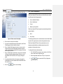
Introduction
Table of Contents
1
Introduction .......................... 12
2
1.1
OfficeConnect Gigabit VPN Firewall ............................ 12
1.2
System Requirements ................................................... 12
1.3
Using this Document ..................................................... 12
1.3.1
Notational conventions ....................................... 12
1.3.2
Typographical conventions .................................. 2
1.3.3
Special messages ................................................. 2
Getting to Know the
OfficeConnect Gigabit VPN
3
2.4.1.3
Defense against DoS Attacks.................. 5
2.4.1.4
Application Command Filtering ............... 5
2.4.1.5
Application Level Gateway (ALG) ........... 6
2.4.1.6
Local Content Filtering ............................. 6
2.4.1.7
Log and Alerts........................................... 6
2.4.2
VPN ........................................................................ 6
2.4.3
WAN Failover & Load Balancing ......................... 7
2.4.4
QoS and Bandwidth Management ...................... 7
2.4.5
Virtual LAN Interfaces (VLAN) ............................. 7
Quick Start Guide .................. 9
3.1
Part 1 — Connecting the Hardware ............................... 9
Firewall .................................. 3
3.1.1
Step 1. Connect an ADSL or a cable
2.1
Parts List........................................................................... 3
3.1.2
Step 2. Connect computers or a LAN.................. 9
2.2
Front Panel ....................................................................... 3
3.1.3
Step 3. Attach the power adapter. ....................... 9
2.3
Rear Panel ....................................................................... 3
3.1.4
Step 4. Turn on the OfficeConnect Gigabit
2.4
Major Features ................................................................. 4
modem. .................................................................. 9
VPN Firewall, the ADSL or cable modem
and power up your computers. .......................... 10
2.4.1
Firewall Features................................................... 4
2.4.1.1
Address Sharing and Management ........ 4
2.4.1.1
ACL (Access Control List)........................ 4
2.4.1.2
Stateful Packet Inspection ....................... 5
3.2
Part 2 — Rack Mounting Instructions........................... 10
3.3
Part 3 — Configuring Your Computers ........................ 11
3.3.1
Before you begin ................................................. 12
3.3.2
Windows® XP PCs: ............................................ 12
OfficeConnect VPN Firewall User’s Manual
Chapter 1.Introduction
3.4
3.3.3
Windows® 2000 PCs: ........................................ 12
5.2
3.3.4
Windows® 95, 98, and Me PCs......................... 13
5.2.1
What is DHCP? ................................................... 26
3.3.5
Windows® NT 4.0 workstations: ........................ 13
5.2.2
Why use DHCP? ................................................. 27
3.3.6
Assigning static IP addresses to your PCs ....... 14
5.2.3
Configuring DHCP Server .................................. 27
5.2.4
Viewing Current DHCP Address
Part 4 — Quick Configuration of the
DHCP (Dynamic Host Control Protocol) ...................... 26
OfficeConnect Gigabit VPN Firewall ............................ 14
3.4.1
Assignments ........................................................ 29
Setting Up the OfficeConnect Gigabit VPN
5.3
Firewall ................................................................. 14
4
3.4.2
Testing Your Setup ............................................. 18
3.4.3
Default Router Settings....................................... 18
5.4
Configuration Manager ........ 21
Log into Configuration Manager ................................... 21
4.2
Functional Layout .......................................................... 21
4.2.1
4.3
5
Commonly Used Buttons and Icons .................. 22
6
Overview of System Configuration ............................... 22
Configuring LAN Settings .... 25
5.1
LAN IP Address ............................................................. 25
5.1.1
LAN IP Configuration Parameters ..................... 25
5.1.2
Configuring the LAN IP Address ........................ 25
5.3.1
Manually add a Fixed DHCP Lease. ................. 29
5.3.2
Import Discovered LAN Hosts as Fixed
DHCP Entries ...................................................... 29
Getting Started with the
4.1
Configuring Fixed DHCP Leases ................................. 29
2
DNS ................................................................................ 30
5.4.1
About DNS........................................................... 30
5.4.2
Assigning DNS Addresses ................................. 30
5.4.3
Configuring DNS Relay ...................................... 30
5.5
Configuring the Port Settings ........................................ 31
5.6
Viewing LAN Statistics .................................................. 32
Configuring VLAN Settings .. 33
6.1
VLAN Overview ............................................................. 33
6.2
VLAN Configuration Parameters .................................. 33
6.3
Configuring the VLAN settings ..................................... 33
OfficeConnect VPN Firewall User’s Manual
7
Chapter 1. Introduction
8.5.2
Configuring Spanning Tree
8.6
Settings ................................ 35
7.1
Spanning Tree Overview .............................................. 35
7.2
Spanning Tree Configuration Parameters ................... 35
7.3
Configuring the Spanning Tree settings....................... 36
7.4
Viewing the Spanning Tree Status ............................... 37
9
Viewing WAN Statistics ................................................. 43
Configuring Routes .............. 45
9.1
Overview of IP Routes................................................... 45
9.1.1
9.2
8
Dynamic Routing using RIP (Routing Information
9.2.1
9.3
WAN Connection Mode ................................................ 39
8.2
PPPoE ............................................................................ 39
8.3
8.4
8.2.1
WAN PPPoE Configuration Parameters ........... 39
8.2.2
Configuring PPPoE for WAN ............................. 40
Do I need to define IP routes? ........................... 45
Protocol) ......................................................................... 45
Configuring WAN Settings ... 39
8.1
Configuring Static IP for WAN ............................ 42
Enabling/Disabling RIP ....................................... 46
Static Routing ................................................................. 46
9.3.1
Static Route Configuration Parameters ............. 46
9.3.2
Adding Static Routes .......................................... 47
9.3.3
Deleting Static Routes ........................................ 47
9.3.4
Viewing the Static Routing Table ....................... 47
PPTP .............................................................................. 40
8.3.1
WAN PPTP Configuration Parameters ............. 40
8.3.2
Configuring PPTP for WAN ................................ 40
10
Dynamic IP ..................................................................... 41
8.4.1
WAN Dynamic IP Configuration
Configuring DDNS ............... 49
10.1
DDNS Configuration Parameters ................................. 49
10.2
Access DDNS Configuration Page............................... 50
10.3
Configuring HTTP DDNS Client ................................... 50
Parameters .......................................................... 41
8.4.2
8.5
11
Configuring Dynamic IP for WAN ...................... 41
Static IP .......................................................................... 42
8.5.1
Configuring Firewall/NAT
Settings ................................ 51
WAN Static IP Configuration Parameters ......... 42
3
OfficeConnect VPN Firewall User’s Manual
Chapter 1.Introduction
11.1
Firewall Overview .......................................................... 51
11.1.1
Stateful Packet Inspection .................................. 51
11.1.2
DoS (Denial of Service) Protection .................... 51
11.1.3
Firewall and Access Control List (ACL) ............. 51
11.4.1
Outbound ACL Rule Configuration
Parameters .......................................................... 57
11.4.2
Access Outbound ACL Rule Configuration
Page ..................................................................... 59
11.1.3.1
Priority Order of ACL Rule ..................... 51
11.1.3.2
Tracking Connection State .................... 52
11.1.4
11.4.3
Modify Outbound ACL Rules ............................. 59
11.4.4
Delete Outbound ACL Rules.............................. 60
11.4.5
Display Outbound ACL Rules ............................ 60
Default ACL Rules .............................................. 52
11.5
11.2
11.2.1
Static (or One-to-One) NAT ............................... 52
11.2.2
NAPT (or One-to-Many NAT)............................. 53
11.2.3
Reverse Static NAT ............................................ 53
11.2.4
Virtual Server (or Reverse NAPT) ..................... 53
11.3
11.5.1
Content Filter Configuration Parameters ........... 60
11.5.2
Access Content Filter Configuration Page ........ 60
11.5.3
Add an Content Filter Rule ................................. 61
11.5.4
Modify an Content Filter Rule............................. 61
11.5.5
Delete an Content Filter Rule ............................. 61
11.5.6
View Configured Content Filter Rules ............... 61
11.5.7
Content Filter Rule Example .............................. 61
Configuring Inbound ACL Rules ................................... 53
11.3.1
Inbound ACL Rule Configuration
Parameters .......................................................... 54
11.3.2
11.6
Access Inbound ACL Rule Configuration
Page ..................................................................... 55
11.3.3
Add Inbound ACL Rules ..................................... 56
11.3.4
Modify Inbound ACL Rules ................................ 57
11.3.5
Delete Inbound ACL Rules................................. 57
11.3.6
Display Inbound ACL Rules ............................... 57
11.4
Configuring Content Filter ............................................. 60
NAT Overview ................................................................ 52
Configuring Advanced Firewall Features ..................... 62
11.6.1
Configuring Self Access Rules........................... 62
11.6.1.1
Self Access Configuration
Parameters ............................................. 62
Configuring Outbound ACL Rules ................................ 57
4
11.6.1.2
Access Self Access Rule Table ............ 64
11.6.1.3
Add a Self Access Rule ......................... 64
11.6.1.4
Modify a Self Access Rule ..................... 64
11.6.1.5
Delete a Self Access Rule ..................... 64
OfficeConnect VPN Firewall User’s Manual
11.6.1.6
Chapter 1. Introduction
View Configured Self Access
11.6.5
Rules ....................................................... 64
11.6.2
Configuring Service List ...................................... 65
11.6.2.1
Service List Configuration
Configuring IP/MAC Binding .............................. 70
11.6.5.1
Adding an IP/MAC binding rule ............. 70
11.6.5.2
Editing an IP/MAC binding rule ............. 71
11.6.5.3
Removing an existing IP/MAC
Parameters ............................................. 65
11.6.2.2
binding rule ............................................. 71
Access Service List Configuration
11.6.6
Configuring Port-Triggering ................................ 71
Page ........................................................ 65
11.6.6.1
11.6.2.3
Add a Service ......................................... 65
11.6.2.4
Modify a Service ..................................... 66
11.6.2.5
Delete a Service ..................................... 66
11.6.2.6
View Configured Services ..................... 66
11.6.3
Port-Triggering feature ........................... 71
Configuring DoS Settings ................................... 66
11.6.3.1
11.6.6.2
Adding an Port-Triggering Rule............. 72
11.6.6.3
Editing an Port-Triggering Rule ............. 72
11.6.6.4
Removing Port-Triggering Rules ........... 73
11.6.7
DoS Protection Configuration
Configuring P2P Service Prevention ................. 73
11.6.7.1
Parameters ............................................. 66
11.6.3.2
Access DoS Configuration Page........... 68
11.6.3.3
Configuring DoS Settings ...................... 68
11.6.4
11.6.7.2
Editing a P2P Service Prevention
Rule ......................................................... 73
11.6.7.3
Removing a P2P Service
Prevention Rule ...................................... 73
Schedule Configuration
Parameters ............................................. 69
11.6.4.2
Adding a P2P Service Prevention
Rule ......................................................... 73
Configuring Schedule ......................................... 68
11.6.4.1
Configuration parameters for the
11.6.8
Access Schedule Configuration
12
Page ........................................................ 69
Configuring Session Limit ................................... 74
Configuring Quality of Service75
11.6.4.3
Add a Schedule ...................................... 69
12.1
Overview ........................................................................ 75
11.6.4.4
Schedule Example ................................. 70
12.2
Define the Maximum Bandwidth................................... 75
5
OfficeConnect VPN Firewall User’s Manual
Chapter 1.Introduction
13
12.3
Defining the QoS Class Object ..................................... 76
12.4
Traffic Classification....................................................... 77
14.3.4
14.4
VPN Connection Examples .......................................... 89
14.4.1
Configuring WAN Load-
Display VPN Rules.............................................. 89
Intranet Scenario – firewall + VPN and no
NAT for VPN traffic ............................................. 89
Balancing & Failover ............ 79
14.4.1.1
Configure Rules on OfficeConnect
Gigabit VPN Firewall 1 (ISR1) ............... 89
14
13.1
Introduction..................................................................... 79
13.2
Configuring WAN Failover ............................................ 79
13.3
Configuring WAN Load-Balancing ............................... 81
14.4.1.2
Gigabit VPN Firewall 2 (ISR2) ............... 91
14.4.1.3
14.5
Configuring IPSec VPN ....... 83
14.1
VPN Tunnel Configuration Parameters ....................... 83
14.2
Establish VPN Connection Using Automatic
15
Keying............................................................................. 85
14.2.1
Configure Rules on OfficeConnect
Add a Rule for VPN Connection Using
Establish Tunnel and Verify ................... 92
Managing VPN User Account ....................................... 92
Configuring L2TP Server ..... 95
15.1
Introduction..................................................................... 95
15.2
L2TP Server Configuration Parameters ....................... 95
15.3
Configuring L2TP Server .............................................. 96
15.4
Viewing Active L2TP Session ....................................... 96
Pre-shared Key ................................................... 86
14.2.2
Modify VPN Rules ............................................... 87
14.2.3
Delete VPN Rules ............................................... 87
14.2.4
Display VPN Rules.............................................. 87
14.3
16
Establish VPN Connection Using Manual Keys .......... 87
14.3.1
Add a Rule for VPN Connection Using
Configuring PPTP Server .... 97
16.1
Introduction..................................................................... 97
16.2
PPTP Server Configuration Parameters ...................... 97
16.3
Configuring PPTP Server.............................................. 98
16.4
Viewing Active PPTP Session ...................................... 98
Manual Key.......................................................... 88
14.3.2
Modify VPN Rules ............................................... 88
14.3.3
Delete VPN Rules ............................................... 88
17
6
System Management......... 101
OfficeConnect VPN Firewall User’s Manual
Chapter 1. Introduction
17.1
Configure Port Mirroring ..............................................101
19.2
Network classes........................................................... 111
17.2
Change the Login Password ......................................101
19.3
Subnet masks .............................................................. 112
17.3
Configuring the Management Interface ..................... 103
17.4
Modify System Information .........................................103
17.5
Setup Date and Time ..................................................104
17.5.1
17.6
20
20.1
View the System Date and Time ..................... 104
System Configuration Management........................... 104
17.6.1
Reset System Configuration ............................ 104
17.6.2
Backup System Configuration.......................... 105
17.6.3
Restore System Configuration ......................... 105
Troubleshooting ................. 115
21
Diagnosing Problem using IP Utilities ........................ 116
20.1.1
ping.....................................................................116
20.1.2
nslookup ............................................................ 117
SAFETY INFORMATION .. 119
Important Safety Information ....................................................119
Wichtige Sicherheitshinweise...................................................119
17.7
Upgrade Firmware ....................................................... 105
17.8
Reset the OfficeConnect Gigabit VPN Firewall .........106
17.9
Logout Configuration Manager ...................................106
Consignes importantes de sécurité .........................................120
22
17.10 Configuring Logging ....................................................106
OBTAINING SUPPORT FOR
YOUR PRODUCT ............. 121
17.11 Configuring SNMP ....................................................... 107
18
ALG Configuration ............. 109
19
IP Addresses, Network Masks,
Register Your Product to Gain Service Benefits.....................121
Troubleshoot Online .................................................................121
Purchase Extended Warranty and Professional Services .....121
Access Software Downloads ...................................................121
and Subnets....................... 111
19.1
Contact Us .................................................................................122
Telephone Technical Support and Repair .............................. 122
IP Addresses ................................................................ 111
19.1.1
Structure of an IP address ................................ 111
7
OfficeConnect VPN Firewall User’s Manual
Chapter 1.Introduction
23
Figure 3.6 System Time Configuration Page ..................................................... 16
END USER SOFTWARE
Figure 3.7 IP Setup Configuration Page ............................................................. 16
LICENCE AGREEMENT ... 129
24
25
Figure 3.8 DHCP Server Configuration Page .................................................... 16
Figure 3.9 WAN PPPoE Configuration Page ..................................................... 17
Regulatory Notices ............ 130
Figure 3.10 WAN Dynamic IP Configuration Page ............................................ 17
24.1.1.1
FCC STATEMENT ............................... 130
Figure 3.11 WAN Static IP Configuration Page ................................................. 18
24.1.1.2
INFORMATION TO THE USER .........130
Figure 4.1 Configuration Manager Login Screen ............................................... 21
24.1.1.3
ICES STATEMENT .............................. 130
Figure 4.2 Typical Configuration Manager Page ............................................... 22
24.1.1.4
CE STATEMENT (EUROPE)..............130
Figure 4.3 Device Summary Page ...................................................................... 23
Glossary............................. 131
Figure 5.1 Interface List........................................................................................ 26
Figure 5.2 IP Setup Configuration Page ............................................................. 26
26
Index .................................. 137
Figure 5.3 DHCP Configuration Page................................................................. 27
Figure 5.4 Host Discovery Configuration Page .................................................. 30
Figure 5.5 Port Setup Configuration Page.......................................................... 31
List of Figures
Figure 5.6 Port Selection...................................................................................... 32
Figure 2.1 Front Panel LEDs ................................................................................. 3
Figure 5.7 LAN Statistics Page............................................................................ 32
Figure 2.2 Rear Panel Connections ...................................................................... 4
Figure 6.1 VLAN Configuration Summary Page ................................................ 34
Figure 3.1 Overview of Hardware Connections ................................................. 10
Figure 6.2 VLAN Configuration Page.................................................................. 34
Figure 3.2 Assembling the rack mount kit .......................................................... 11
Figure 6.3 Select a VLAN Membership Type ..................................................... 34
Figure 3.3 Rack Mounting .................................................................................... 11
Figure 6.4 VLAN Membership assignment ........................................................ 34
Figure 3.4 Login Screen ....................................................................................... 15
Figure 7.1 Spanning Tree Configuration Page................................................... 36
Figure 3.5 System Access Configuration Page ................................................. 15
Figure 7.2 RSTP/STP Status Page..................................................................... 37
8
OfficeConnect VPN Firewall User’s Manual
Chapter 1. Introduction
Figure 8.1 WAN Connection Type Configuration ............................................... 39
Figure 11.14. Schedule Example – Create a Schedule .................................... 70
Figure 8.2 WAN Dynamic IP (DHCP client) Configuration Page ...................... 42
Figure 11.15. Schedule Example – Deny FTP Access for MISgroup1 During
OfficeHours ................................................................................................... 70
Figure 8.3 WAN Static IP Configuration Page ................................................... 42
Figure 11.16 IP/MAC Binding Configuration Page ............................................ 71
Figure 8.4 WAN Statistics Page .......................................................................... 43
Figure 11.17 Port-Triggering Configuration Page .............................................. 72
Figure 9.1 Routing Configuration Page ............................................................. 45
Figure 12.1 Interface Settings List Table ............................................................ 75
Figure 9.2 RIP Configuration Page ..................................................................... 46
Figure 12.2 Maximum Interface Bandwidth Configuration Page ...................... 76
Figure 9.3 Viewing Routing Table ...................................................................... 47
Figure 12.3 QoS Configuration Page .................................................................. 76
Figure 10.1 Network Diagram for HTTP DDNS ................................................. 49
Figure 12.4 QoS Class Definition Page .............................................................. 76
Figure 10.2 HTTP DDNS Configuration Page ................................................... 50
Figure 12.5 Add a new QoS Class Object .......................................................... 77
Figure 11.1 One-to-One NAT and One-to-Many NAT ....................................... 53
Figure 12.6 QoS Policy Configuration Page....................................................... 78
Figure 11.2. Inbound ACL Configuration Page .................................................. 54
Figure 13.1 WAN Link Mgmt Configuration Page .............................................. 80
Figure 11.3 ACL Rule List Table ......................................................................... 56
Figure 13.2 Enable the WAN Failover ................................................................ 80
Figure 11.4 Tab Buttons for Different Traffic Types ........................................... 56
Figure 14.1. IPSec VPN Policy List Table .......................................................... 86
Figure 11.5. Inbound ACL Configuration Example ............................................ 56
Figure 14.2. VPN Tunnel Configuration Page – Pre-shared Key Mode........... 87
Figure 11.6. Outbound ACL Configuration Page ............................................... 57
Figure 14.3. VPN Tunnel Configuration Page – Manual Key Mode ................. 88
Figure 11.7 Outbound ACL Configuration Example .......................................... 59
Figure 14.4. Typical Intranet Network Diagram .................................................. 89
Figure 11.8. Content Filter Configuration Page .................................................. 61
Figure 14.5. Intranet VPN Policy Configuration on ISR1 ................................... 90
Figure 11.9. Content filter Rule Example ............................................................ 62
Figure 14.6. Intranet VPN Policy Configuration on ISR2 ................................... 91
Figure 11.10. Self Access Rule Table Page....................................................... 62
Figure 14.7 VPN User Account Configuration Page.......................................... 93
Figure 11.11. Service List Configuration Page ................................................... 65
Figure 14.8 Configuring VPN User Account ....................................................... 93
Figure 11.12. DoS Configuration Page ............................................................... 68
Figure 14.9 Editing an existing VPN User .......................................................... 93
Figure 11.13. Schedule Configuration Page ...................................................... 69
9
OfficeConnect VPN Firewall User’s Manual
Chapter 1.Introduction
Figure 14.10 VPN User Group Configuration Page ........................................... 94
List of Tables
Figure 14.11 Configuring a User Group.............................................................. 94
Table 2.1 Front Panel Label and LEDs................................................................. 3
Figure 15.1. L2TP Server Configuration Page ................................................... 96
Table 2.2 Rear Panel Labels and LEDs ............................................................... 4
Figure 15.2. Viewing Active L2TP Sessions....................................................... 96
Table 2.3 DoS Attacks ........................................................................................... 5
Figure 16.1. PPTP Server Configuration Page .................................................. 97
Table 2.4 VPN Features of the OfficeConnect Gigabit VPN Firewall ................. 6
Figure 16.2. Viewing Active PPTP Sessions ...................................................... 98
Table 3.1 LED Indicators ..................................................................................... 10
Figure 17.1 Port Mirroring Configuration Page.................................................101
Table 3.2 Default Settings Summary .................................................................. 19
Figure 17.2. System Access Account Configuration Page.............................. 102
Table 4.1 Description of Commonly Used Buttons and Icons .......................... 22
Figure 17.3 Management Interface Configuration Page .................................103
Table 5.1 LAN IP Configuration Parameters ...................................................... 25
Figure 17.4. System Information Configuration Page ......................................103
Table 5.2 DHCP Configuration Parameters ....................................................... 27
Figure 17.5. Date and Time Configuration Page .............................................104
Table 5.3 DHCP Address Assignment ............................................................... 29
Figure 17.6. Default Setting Configuration Page..............................................105
Table 6.1 VLAN Configuration Parameters ........................................................ 33
Figure 17.7. Windows File Browser ..................................................................105
Table 7.1 Spanning Tree Configuration Parameters ......................................... 35
Figure 17.8. Firmware Upgrade Page .............................................................. 106
Table 8.1 WAN PPPoE Configuration Parameters ............................................ 39
Figure 17.9. Confirmation for Closing Browser (IE) .........................................106
Table 8.2 WAN PPTP Configuration Parameters .............................................. 40
Figure 17.10 Logging Configuration Page ........................................................ 107
Table 8.3 WAN Dynamic IP Configuration Parameters .................................... 41
Figure 17.11 SNMP Community Configuration Page ......................................108
Table 8.4 WAN Static IP Configuration Parameters .......................................... 42
Figure 17.12 SNMP Trap Configuration Page .................................................108
Table 9.1 Static Route Configuration Parameters ............................................. 46
Figure 20.1. Using the ping Utility......................................................................117
Table 10.1 DDNS Configuration Parameters ..................................................... 49
Figure 20.2. Using the nslookup Utility ............................................................. 118
Table 11.1. Inbound ACL Rule Configuration Parameters ................................ 54
Table 11.2. Outbound ACL Rule Configuration Parameters ............................. 57
10
OfficeConnect VPN Firewall User’s Manual
Chapter 1. Introduction
Table 11.3. Content Filter Configuration Parameters ........................................ 60
Table 11.4. Self Access Configuration Parameters ........................................... 62
Table 11.5. Service List configuration parameters ............................................. 65
Table 11.6. DoS Protection Configuration Parameters ..................................... 66
Table 11.7. Schedule Configuration Parameters ............................................... 69
Table 11.8 Port-Triggering Configuration Parameters ....................................... 71
Table 11.9 P2P Service Prevention Configuration Parameters ........................ 73
Table 11.10 Session Limit Configuration Parameters ....................................... 74
Table 13.1 WAN Failover Configuration Parameters ........................................ 79
Table 14.1. VPNTtunnel Configuration Parameter ............................................ 83
Table 14.2. Outbound Un-translated Firewall Rule for VPN Packets on ISR1 90
Table 14.3. Inbound Un-translated Firewall Rule for VPN Packets on ISR1 ... 90
Table 14.4. Outbound Un-translated Firewall Rule for VPN Packets on ISR1 92
Table 14.5. Inbound Un-translated Firewall Rule for VPN Packets on ISR1 ... 92
Table 15.1. L2TP Server Configuration Parameters.......................................... 95
Table 16.1. PPTP Server Configuration Parameters ......................................... 97
Table 17.1 System Access Account Configuration Parameters ..................... 102
Table 18.1. Supported ALG ...............................................................................109
Table 19.1. IP Address structure .......................................................................111
11
OfficeConnect VPN Firewall User’s Manual
Chapter 1.Introduction
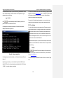
using Stateful Packet Inspection (SPI), web content filtering, logging and
1
reporting.
Introduction
1.2
System Requirements
Welcome to the world of networking with 3Com. In the modern business
environment, communication and sharing information is crucial. Computer
In order to use the OfficeConnect Gigabit VPN Firewall for Internet access, you
networks have proved to be one of the fastest modes of communication but, until
must have the following:
recently, only large businesses could afford the networking advantage. The
OfficeConnect product range from 3Com has changed all this, bringing networks
ADSL or cable modem and the corresponding service up and running, with
at least one public Internet address assigned to your WAN
to the small office.
The products that compose the OfficeConnect line give you, the small office
One or more computers each containing an Ethernet 10Base-T/100BaseT/1000Base-T network interface card (NIC)
user, the same power, flexibility, and protection that has been available only to
large corporations. Now, you can network the computers in your office, connect
(Optional) An Ethernet switch, if you are connecting the device to more
than four computers on an Ethernet network.
them all to a single Internet outlet, and harness the combined power of all of your
computers.
For system configuration using the supplied web-based program: a web
browser such as Internet Explorer v5.5 or later.
This User Manual will show you how to set up the OfficeConnect Gigabit VPN
1.3
Firewall, and how to customize its configuration to get the most out of this
Using this Document
product.
1.3.1
1.1
OfficeConnect Gigabit VPN Firewall
Notational conventions
Acronyms are defined the first time they appear in text and in the glossary
(Appendix 25).
The OfficeConnect Gigabit VPN Firewall is designed to provide a robust, secure
solution for multi-site small businesses. This completely equipped, broadband-
For brevity, the OfficeConnect Gigabit VPN Firewall is sometimes referred
to as ―the router.‖
capable Virtual Private Network (VPN) firewall prevents unauthorised external
access to your network — and by creating Virtual Private Networks (VPNs) —
The terms LAN and network are used interchangeably to refer to a group
of Ethernet-connected computers at one site.
encrypted links to other private networks. The OfficeConnect Gigabit VPN
Firewall also provides Denial of Service (DoS) protection and intrusion detection
12
OfficeConnect VPN Firewall User’s Manual
Chapter 1.Introduction
1.3.2
Typographical conventions
Italics are used to identify terms that are defined in the glossary (Chapter
25).
Boldface type text is used for items you select from menus and drop-down
lists, and text strings you type when prompted by the program.
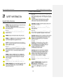
1.3.3
Special messages
This document uses the following icons to call your attention to specific
instructions or explanations.
Provides clarification or non-essential information on the current
Note
topic.
Explains terms or acronyms that may be unfamiliar to many
Definition
readers. These terms are also included in the Glossary.
Provides messages of high importance, including messages
relating to personal safety or system integrity.
WARNING
2
OfficeConnect VPN Firewall User’s Manual
Chapter 2. Getting to Know the OfficeConnect Gigabit VPN Firewall
POWER
2
Getting to Know the
OfficeConnect Gigabit VPN
Firewall
WAN1
WAN2
TEST LED
LAN1/DMZ1
LAN2/DMZ2
DMZ1 LED
LAN3 ~ LAN6
CONSOLE
DMZ2 LED
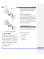
Reset
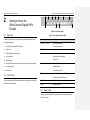
Figure 2.1 Front Panel LEDs
2.1
Parts List
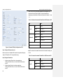
Table 2.1 Front Panel Label and LEDs
In addition to this document, your OfficeConnect Gigabit VPN Firewall should
Label
Color
Function
come with the following:
POWER
Green
On: Unit is powered on
The OfficeConnect Gigabit VPN Firewall
Power cord
STATUS
Amber
(For factory testing only)
RJ45-to-DB9 console port cable
Link/Act
Green
Green: Link is established
Four rubber feet
Flashing: Data is transmitted
Rack mount kit
Off: No Link
One CD-ROM containing: The 3Com detect program and this user guide.
One Warranty Flyer
Amber: 100M link
Release note
Off: 10M link or no link
Off: Unit is powered off
1000
Green/Amber
DMZ
2.2
Green
Front Panel
The front panel contains LED indicators that show the status of the unit and the
ports for the data connections.
Green: Gigabit link
Green: This port is used as DMZ port
Off: This port is used as LAN port
CONSOLE
RJ-45 serial port for console management
Reset
Resets the device
2.3
Rear Panel
The rear panel contains the AC inlet and power switch. See Figure 2.2 Rear
Panel Connections.
3
OfficeConnect VPN Firewall User’s Manual
Chapter 2. Getting to Know the OfficeConnect Gigabit VPN Firewall
AC Inlet
WAN Failover & Load Balancing
2.4.1.1
Address Sharing and Management
The OfficeConnect Gigabit VPN Firewall provides NAT to share a single high-
Power Switch
speed Internet connection and to save the cost of multiple connections required
Figure 2.2 Rear Panel Connections
for the hosts on the LAN segments connected to the OfficeConnect Gigabit VPN
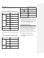
Table 2.2 Rear Panel Labels and LEDs
Label
Firewall. This feature conceals network address and prevents them from
becoming public. It maps unregistered IP addresses of hosts connected to the
Function
LAN with valid ones for Internet access. The OfficeConnect Gigabit VPN Firewall
Switches the unit on and off
also provides reverse NAT capability, which enables SOHO users to host
various services such as e-mail servers, web servers, etc. The NAT rules drive
POWER
2.4
Connects to the supplied power adapter
the translation mechanism at the NAT router.
2.4.1.1
Major Features
ACL (Access Control List)
ACL rule is one of the basic building blocks for network security. Firewall
2.4.1
Firewall Features
monitors each individual packet, decodes the header information of inbound and
The Firewall as implemented in the OfficeConnect Gigabit VPN Firewall provides
outbound traffic and then either blocks the packet from passing or allows it to
the following features to protect your network from being attacked and to prevent
pass based on the contents of the source address, destination address, source
your network from being used as the springboard for attacks.
port, destination port, protocol and other criterion, e.g. application filter,
Address Sharing and Management
Packet Filtering
Stateful Packet Inspection
Defense against Denial of Service Attacks
Application Content Filtering
Log and Alert
Remote Access
Keyword based Content filtering
Schedules, defined in the ACL rules.
ACL is a very appropriate measure for providing isolation of one subnet from
another. It can be used as the first line of defense in the network to block
inbound packets of specific types from ever reaching the protected network.
The OfficeConnect Gigabit VPN Firewall’s ACL methodology supports:
Filtering based on destination and source IP address, port number and
protocol
4
Filter Rule priorities
Time based filters
OfficeConnect VPN Firewall User’s Manual
Chapter 2 Getting to Know the OfficeConnect Gigabit VPN Firewall
Application specific filters
2.4.1.2
ICMP Attacks
Stateful Packet Inspection
Flooders
The OfficeConnect Gigabit VPN Firewall uses ―stateful packet inspection‖ that
extracts state-related information required for the security decision from the
Port Scans
packet and maintains this information for evaluating subsequent connection
attempts. It has awareness of application and creates dynamic sessions that
allow dynamic connections so that no ports need to be opened other than the
TCP Attacks
required ones. This provides a solution which is highly secure and that offers
scalability and extensibility.
2.4.1.3
Protection with PF Rules
Defense against DoS Attacks
Ping of Death, Smurf, Twinge
ICMP Flooder, UDP Flooder, SYN
Flooder
TCP XMAS Scan, TCP Null Scan
TCP SYN Scan, TCP Stealth Scan
TCP sequence number prediction, TCP
out-of sequence attacks
Echo-Chargen, Ascend Kill
IP Spoofing, LAND, Targa, Tentacle
The OfficeConnect Gigabit VPN Firewall has an Attack Defense Engine that
Miscellaneous Attacks
protects internal networks from known types of Internet attacks. It provides
MIME Flood, Winnuke, FTP Bounce, IP
unaligned time stamp attack
automatic protection from Denial of Service (DoS) attacks such as SYN flooding,
IP smurfing, LAND, Ping of Death and all re-assembly attacks. It can drop ICMP
2.4.1.4
redirects and IP loose/strict source routing packets. For example, the
The OfficeConnect Gigabit VPN Firewall allows network administrators to block,
OfficeConnect Gigabit VPN Firewall provides protection from ―WinNuke‖, a
monitor, and report on network users access to non-business and objectionable
widely used program to remotely crash unprotected Windows systems in the
content. This high-performance content access control results in increased
Internet. The OfficeConnect Gigabit VPN Firewall also provides protection from a
productivity, lower bandwidth usage and reduced legal liability.
variety of common Internet attacks such as IP Spoofing, Ping of Death, Land
The OfficeConnect Gigabit VPN Firewall has the ability to handle active content
Attack, Reassembly and SYN flooding.
filtering on certain application protocols such as HTTP, FTP, SMTP and RPC.
The type of attack protections provided by the OfficeConnect Gigabit VPN
Firewall are listed in Table 2.3.
HTTP – You can define HTTP extension based filtering schemes for
blocking
ActiveX
Table 2.3 DoS Attacks
Type of Attack
Application Command Filtering
Java Archive
Name of Attacks
Java Applets
Re-assembly attacks
Bonk, Boink, Teardrop (New Tear),
URLs based on file extensions.
Overdrop, Opentear, Syndrop, Jolt
5
OfficeConnect VPN Firewall User’s Manual
Chapter 2. Getting to Know the OfficeConnect Gigabit VPN Firewall
2.4.1.5
Application Level Gateway (ALG)
Maintains at a minimum, log details such as, time of packet arrival,
description of action taken by Firewall and reason for action.
Applications such as FTP, games etc., open connections dynamically based on
the respective application parameter. To go through the firewall on the
Supports the UNIX Syslog format.
OfficeConnect Gigabit VPN Firewall, packets pertaining to an application, require
Sends log report e-mails as scheduled by the network administrator or by
a corresponding allow rule. In the absence of such rules, the packets will be
default when the log file is full.
dropped by the OfficeConnect Gigabit VPN Firewall. As it is not feasible to
create policies for numerous applications dynamically (at the same time without
compromising security), intelligence in the form of Application Level Gateways
All the messages are sent in the WELF format.
ICMP logging to show code and type.
(ALG), is built to parse packets for applications and open dynamic associations.
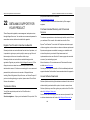
2.4.2
The OfficeConnect Gigabit VPN Firewall provides a number of ALGs for popular
The introduction of broadband Internet access at an affordable price has
applications such as FTP, H.323, RTSP, SIP, etc.
attracted a large number of users to use the Internet for business. Large-scale
2.4.1.6
use of a very open public network such as, the Internet comes with a lot of
Local Content Filtering
advantages and associated risks. These risks include the lack of confidentiality
A set of keywords that should not appear in the URL (Uniform Resource Locator,
of data being sent and the authenticity of the identities of the parties involved in
e.g. www.yahoo.com) can be defined. Any URL containing one or more of these
the exchange of data. The VPN supported in the OfficeConnect Gigabit VPN
keywords will be blocked. This is a policy independent feature i.e. it cannot be
Firewall is intended to resolve these issues at an affordable price.
associated to ACL rules. This feature can be independently enabled or disabled,
but works only if firewall is enabled.
2.4.1.7
VPN
The VPN supported by the OfficeConnect Gigabit VPN Firewall is IPSec
compliant. Packets sent via VPN are encrypted to maintain privacy. The
Log and Alerts
encrypted packets are then tunneled through a public network. As a result,
Events in the network, that could be attempts to affect its security, are recorded
tunnel participants enjoy the same security features and facilities that are
in the OfficeConnect Gigabit VPN Firewall System log file. Event details are
available only to members of private networks at a reduced cost.
recorded in WELF (WebTrends Enhanced Log Format ) format so that statistical
tools can be used to generate custom reports. The OfficeConnect Gigabit VPN
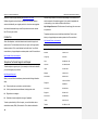
The following table lists the VPN features supported by the OfficeConnect
Firewall can also forward Syslog information to a Syslog server on a private
Gigabit VPN Firewall:
network.
Table 2.4 VPN Features of the OfficeConnect Gigabit VPN Firewall
The OfficeConnect Gigabit VPN Firewall supports:
Features
Alerts sent to the administrator via e-mail.
Transport Mode for Client-Client Connectivity
6
OfficeConnect VPN Firewall User’s Manual
Chapter 2 Getting to Know the OfficeConnect Gigabit VPN Firewall
allows OfficeConnect Gigabit VPN Firewall to maintain a persistent connection
Tunnel Mode for Network-Network Connectivity
for WAN port traffic by failing over to the backup WAN port.
IP Fragmentation and Reassembly
The primary and secondary WAN ports can also be used in a more dynamic
IPSec
Support
Hardware Encryption Algorithm
DES, 3DES, AES
flows between the two WAN ports. This feature is referred to as load balancing.
Hardware Authentication Algorithm
MD5, SHA-1
2.4.4
Transforms
ESP, AH
QoS and Bandwidth Management function allows voice and data traffic to flow
Key Management
IKE , IKEv2
setup, where the administrator can choose a method of dividing outbound traffic
QoS and Bandwidth Management
through where voice traffic is transmitted in the highest priority. With DiffServ
QoS enabled, it guarantees voice packets to have first priority to pass through a
Mode configuration for IKE
Main Mode, Aggressive Mode, Quick
DiffServ QoS enabled devices such as router or switch.
Mode
2.4.5
Virtual LAN Interfaces (VLAN)
The Virtual Local Area Network (VLAN) feature allows OfficeConnect Gigabit
Site-to-Site VPN connection – Site-to-Site VPN connection is an alternative
VPN Firewall to be partitioned into non-interacting network domains.
WAN infrastructure that is used to connect branch offices, home offices, or
business partners’ sites to all or portions of a company’s network.
Remote Access VPN – Corporations use VPN to establish secure, end-toend private network connections over a public networking infrastructure.
VPN have become the logical solution for remote access connectivity.
Deploying a remote access VPN enables corporations to reduce
communications expenses by leveraging the local dial-up infrastructure of
Internet Service Providers. At the same time, VPNs allow mobile workers,
telecommuters and day extenders to take advantage of broadband
connectivity.
2.4.3
WAN Failover & Load Balancing
WAN Failover and Load Balancing allows you to designate the one of the
assigned interfaces as a backup WAN port. If the primary WAN port is down
and/or unavailable, traffic is only routed through the backup WAN port. This
7
OfficeConnect VPN Firewall User’s Manual
Chapter 3. Quick Start Guide
RISK OF EXPLOSION IF BATTERY IS REPLACED BY AN
3
Quick Start Guide
INCORRECT TYPE.
WARNING
DISPOSE OF USED BATTERIES
ACCORDING TO THE INSTRUCTIONS
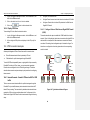
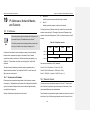
This Quick Start Guide provides basic instructions for connecting the
Figure 3.1 illustrates the hardware connections. Please follow the steps that
OfficeConnect Gigabit VPN Firewall to a computer or a LAN and to the Internet.
follow for specific instructions.
Part 1 provides instructions to set up the hardware.
3.1.1
Part 2 describes how to configure Internet properties on your computer(s).
For the OfficeConnect Gigabit VPN Firewall: Connect one end of the Ethernet
Part 3 shows you how to configure basic settings on the OfficeConnect
cable to the port labeled WAN on the front panel of the device. Connect the other
Gigabit VPN Firewall to get your LAN connected to the Internet.
end to the Ethernet port on the ADSL or cable modem.
Step 1. Connect an ADSL or a cable modem.
After setting up and configuring the device, you can follow the instructions on
3.1.2
page 18 to verify that it is working properly.
If your LAN has no more than 6 computers, you can use an Ethernet cable to
This Quick Start Guide assumes that you have already established ADSL or
connect computers directly to the built-in switch on the device. Note that you
cable modem service with your Internet service provider (ISP). These
should attach one end of the Ethernet cable to any of the port labeled LAN1 –
instructions provide a basic configuration that should be compatible with your
LAN6 on the front panel of the device and connect the other end to the Ethernet
home or small office network setup. Refer to the subsequent chapters for
port of a computer.
additional configuration instructions.
If your LAN has more than 6 computers, you can attach one end of an Ethernet
3.1
Part 1 — Connecting the Hardware
Step 2. Connect computers or a LAN.
cable to a hub or a switch (probably an uplink port; please refer to the hub or
switch documentations for instructions) and the other to the Ethernet switch port
In Part 1, you connect the device to an ADSL or a cable modem (which in turn is
(labeled LAN1 – LAN6) on the OfficeConnect Gigabit VPN Firewall.
connected to a phone jack or a cable outlet), the power outlet, and your
Note that either the crossover or straight-through Ethernet cable can be used to
computer or network.
connect the built-in switch and computers, hubs or switches as the built-in switch
is smart enough to make connections with either type of cables.
Before you begin, turn the power off for all devices. These
WARNING
include your computer(s), your LAN hub/switch (if applicable),
3.1.3
and the OfficeConnect Gigabit VPN Firewall.
Connect the AC power adapter to the POWER connector on the back of the
Step 3. Attach the power adapter.
device and plug in the adapter to a wall outlet or a power strip.
9
OfficeConnect Gigabit VPN Firewall User’s Manual
Chapter 3. Quick Start Guide
3.1.4
Step 4. Turn on the OfficeConnect Gigabit VPN
Firewall, the ADSL or cable modem and power up
your computers.
power source.
Press the Power switch on the rear panel of the OfficeConnect Gigabit VPN
LAN1 –
Solid green to indicate that the device can communicate with
LAN6
your LAN or flashing when the device is sending or receiving
data from your LAN computer.
Firewall to the ON position. Turn on your ADSL or cable modem. Turn on and
WAN1 –
boot up your computer(s) and any LAN devices such as hubs or switches.
WAN2
Solid green to indicate that the device has successfully
established a connection with your ISP or flashing when the
device is sending or receiving data from the Internet.
If the LEDs illuminate as expected, the OfficeConnect Gigabit VPN Firewall
hardware is working properly.
3.2
Part 2 — Rack Mounting Instructions
The OfficeConnect Gigabit VPN Firewall is 1U high and will fit a 19-inch rack if
the rack mount kit is properly installed.
Elevated Operating Ambient - If installed in a closed or multiunit rack assembly, the operating ambient temperature of the
rack environment may be greater than room ambient. Therefore,
consideration should be given to installing the equipment in an
WARNING
Figure 3.1 Overview of Hardware Connections
environment compatible with the maximum ambient temperature
(Tma) specified by the manufacturer.
You should verify that the LEDs are illuminated as indicated in Table 3.1.
Reduced Air Flow - Installation of the equipment in a rack
Table 3.1 LED Indicators
should be such that the amount of air flow required for safe
This LED:
POWER
...should be:
WARNING
Solid green to indicate that the device is turned on. If this light
is not on, check if the power adapter is attached to the
OfficeConnect Gigabit VPN Firewall and if it is plugged into a
10
operation of the equipment is not compromised.
OfficeConnect Gigabit VPN Firewall User’s Manual
Chapter 3. Quick Start Guide
Mechanical Loading - Mounting of the equipment in the rack
should be such that a hazardous condition is not achieved due to
WARNING
uneven mechanical loading.
Circuit Overloading - Consideration should be given to the
connection of the equipment to the supply circuit and the effect
that overloading of the circuits might have on overcurrent
protection and supply wiring. Appropriate consideration of
WARNING
equipment nameplate ratings should be used when addressing
Figure 3.2 Assembling the rack mount kit
this concern.
Reliable Earthing - Reliable earthing of rack-mounted equipment
should be maintained. Particular attention should be given to
supply connections other than direct connections to the branch
WARNING
circuit (e.g. use of power strips).
Follow these instructions to install OfficeConnect Gigabit VPN Firewall to your
19-inch rack:
1. Place the unit the right way up on a hard, flat surface with the front
facing towards you.
2. Locate a mounting bracket over the mounting holes on one side of
the unit, as shown in Figure 3.2 below.
3. Insert the two screws and fully tighten with a suitable screwdriver.
4. Repeat the two previous steps for the other side of the unit.
Figure 3.3 Rack Mounting
5. Insert the unit into the 19-inch rack and secure with suitable screws
(not provided).
3.3
Part 3 — Configuring Your Computers
6. Reconnect all cables.
Part 3 of the Quick Start Guide provides instructions for configuring the Internet
settings on your computers to work with the OfficeConnect Gigabit VPN Firewall.
11
OfficeConnect Gigabit VPN Firewall User’s Manual
Chapter 3. Quick Start Guide
3.3.1
6. Click <OK> button twice to confirm your changes, and close the
Control Panel.
Before you begin
By default, the OfficeConnect Gigabit VPN Firewall automatically assigns all
3.3.3
required Internet settings to your PCs. You need only to configure the PCs to
First, check for the IP protocol and, if necessary, install it:
accept the information when it is assigned.
Note
Windows® 2000 PCs:
In some cases, you may want to configure network settings
1. In the Windows task bar, click the <Start> button, point to Settings,
and then click Control Panel.
manually to some or all of your computers rather than allow the
2. Double-click the Network and Dial-up Connections icon.
OfficeConnect Gigabit VPN Firewall to do so. See “Assigning static
3. In the Network and Dial-up Connections window, right-click the
Local Area Connection icon, and then select Properties.
IP addresses to your PCs” in page 14 for instructions.
The Local Area Connection Properties dialog box displays a list of
currently installed network components. If the list includes Internet
If you have connected your PC via Ethernet to the OfficeConnect Gigabit
Protocol (TCP/IP), then the protocol has already been enabled. Skip
VPN Firewall, follow the instructions that correspond to the operating
to step 10.
system installed on your PC.
3.3.2
4. If Internet Protocol (TCP/IP) does not display as an installed
component, click <Install> button.
5. In the Select Network Component Type dialog box, select Protocol,
and then click <Add> button.
Windows® XP PCs:
1. In the Windows task bar, click the <Start> button, and then click
Control Panel.
6. Select Internet Protocol (TCP/IP) in the Network Protocols list, and
then click <OK> button.
2. Double-click the Network Connections icon.
You may be prompted to install files from your Windows 2000
3. In the LAN or High-Speed Internet window, right-click on icon
corresponding to your network interface card (NIC) and select
Properties. (Often this icon is labeled Local Area Connection).
installation CD or other media. Follow the instructions to install the
files.
The Local Area Connection dialog box displays with a list of currently
7. If prompted, click <OK> button to restart your computer with the new
settings.
installed network items.
Next, configure the PCs to accept IP addresses assigned by the
4. Ensure that the check box to the left of the item labeled Internet
Protocol TCP/IP is checked, and click <Properties> button.
OfficeConnect Gigabit VPN Firewall:
5. In the Internet Protocol (TCP/IP) Properties dialog box, click the
radio button labeled Obtain an IP address automatically. Also click
the radio button labeled Obtain DNS server address
automatically.
8. In the Control Panel, double-click the Network and Dial-up
Connections icon.
9. In Network and Dial-up Connections window, right-click the Local
Area Connection icon, and then select Properties.
12
OfficeConnect Gigabit VPN Firewall User’s Manual
Chapter 3. Quick Start Guide
10. In the Local Area Connection Properties dialog box, select Internet
Protocol (TCP/IP), and then click <Properties> button.
7. In the Control Panel, double-click the Network icon.
8. In the Network dialog box, select an entry started with ―TCP/IP ”
and the name of your network adapter, and then click <Properties>
button.
11. In the Internet Protocol (TCP/IP) Properties dialog box, click the
radio button labeled Obtain an IP address automatically. Also click
the radio button labeled Obtain DNS server address
automatically.
9. In the TCP/IP Properties dialog box, click the radio button labeled
Obtain an IP address automatically.
12. Click <OK> button twice to confirm and save your changes, and then
close the Control Panel.
3.3.4
10. In the TCP/IP Properties dialog box, click the ―Default Gateway‖ tab.
Enter 192.168.1.1 (the default LAN port IP address of the
OfficeConnect Gigabit VPN Firewall) in the ―New gateway‖ address
field and click <Add> button to add the default gateway entry.
Windows® 95, 98, and Me PCs
1. In the Windows task bar, click the <Start> button, point to Settings,
and then click Control Panel.
11. Click <OK> button twice to confirm and save your changes, and then
close the Control Panel.
2. Double-click the Network icon.
12. If prompted to restart your computer, click <OK> button to do so with
the new settings.
In the Network dialog box, look for an entry started w/ ―TCP/IP ‖
and the name of your network adapter, and then click <Properties>
3.3.5
button. You may have to scroll down the list to find this entry. If the list
First, check for the IP protocol and, if necessary, install it:
includes such an entry, then the TCP/IP protocol has already been
Windows® NT 4.0 workstations:
1. In the Windows NT task bar, click the <Start> button, point to
Settings, and then click Control Panel.
enabled. Skip to step 8.
7. In the Control Panel window, double click the Network icon.
3. If Internet Protocol (TCP/IP) does not display as an installed
component, click <Add> button.
8. In the Network dialog box, click the Protocols tab.
4. In the Select Network Component Type dialog box, select Protocol,
and then click <Add> button.
The Protocols tab displays a list of currently installed network
protocols. If the list includes TCP/IP Protocol, then the protocol has
5. Select Microsoft in the Manufacturers list box, and then click TCP/IP
in the Network Protocols list, box and then click <OK> button.
already been enabled. Skip to step 14.
You may be prompted to install files from your Windows 95, 98 or Me
9. If TCP/IP does not display as an installed component, click <Add>
button.
installation CD or other media. Follow the instructions to install the
10. In the Select Network Protocol dialog box, select TCP/IP, and then
click <OK> button.
files.
6. If prompted, click <OK> button to restart your computer with the new
settings.
You may be prompted to install files from your Windows NT
installation CD or other media. Follow the instructions to install the
Next, configure the PCs to accept IP information assigned by the
files.
OfficeConnect Gigabit VPN Firewall:
13
OfficeConnect Gigabit VPN Firewall User’s Manual
Chapter 3. Quick Start Guide
After all files are installed, a window displays to inform you that a
the subnet mask and 192.168.1.1 for the default gateway. These settings may
TCP/IP service called DHCP can be set up to dynamically assign IP
be changed later to reflect your true network environment.
information.
On each PC to which you want to assign static information, follow the
11. Click <Yes> button to continue, and then click <OK> button if
prompted to restart your computer.
instructions on pages 12 through 13 relating only to checking for and/or installing
the IP protocol. Once it is installed, continue to follow the instructions for
Next, configure the PCs to accept IP addresses assigned by the
displaying each of the Internet Protocol (TCP/IP) properties. Instead of enabling
OfficeConnect Gigabit VPN Firewall:
dynamic assignment of the IP addresses for the computer, DNS server, and
default gateway, click the radio buttons that enable you to enter the information
12. Open the Control Panel window, and then double-click the Network
icon.
manually.
13. In the Network dialog box, click the Protocols tab.
Your PCs must have IP addresses that place them in the same
14. In the Protocols tab, select TCP/IP, and then click <Properties>
button.
subnet as the OfficeConnect Gigabit VPN Firewall’s LAN port. If you
15. In the Microsoft TCP/IP Properties dialog box, click the radio button
labeled Obtain an IP address from a DHCP server.
manually assign IP information to all your LAN PCs, you can follow
Note
the instructions in Chapter 5 to change the LAN port IP address
16. Click <OK> button twice to confirm and save your changes, and then
close the Control Panel.
3.3.6
accordingly.
Assigning static IP addresses to your PCs
3.4 Part 4 — Quick Configuration of the
OfficeConnect Gigabit VPN Firewall
In some cases, you may want to assign IP addresses to some or all of your PCs
directly (often called ―statically‖), rather than allowing the OfficeConnect Gigabit
VPN Firewall to assign them. This option may be desirable (but not required) if:
In Part 4, you log into the Configuration Manager on the OfficeConnect Gigabit
You have obtained one or more public IP addresses that you want to
VPN Firewall and configure basic settings for your Internet connection. Your ISP
always associate with specific computers (for example, if you are using a
should provide you with the necessary information to complete this step. Note
computer as a public web server).
the intent here is to quickly get the OfficeConnect Gigabit VPN Firewall up and
You maintain different subnets on your LAN.
running, instructions are concise. You may refer to corresponding chapters for
However, during the first time configuration of your OfficeConnect Gigabit VPN
more details.
Firewall, you must assign an IP address in the 192.168.1.0 network for your PC,
3.4.1
say 192.168.1.2, in order to establish connection between the OfficeConnect
Setting Up the OfficeConnect Gigabit VPN Firewall
Follow these instructions to setup the OfficeConnect Gigabit VPN Firewall:
Gigabit VPN Firewall and your PC as the default LAN IP on OfficeConnect
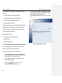
1. Before accessing the Configuration Manager in the OfficeConnect
Gigabit VPN Firewall, make sure that the HTTP proxy setting is
Gigabit VPN Firewall is pre-configured as 192.168.1.1. Enter 255.255.255.0 for
14
OfficeConnect Gigabit VPN Firewall User’s Manual
Chapter 3. Quick Start Guide
disabled in your browser. In IE, click ―Tools‖ ―Internet Options…‖
―Connections‖ tab ―LAN settings…‖ and then uncheck ―Use
proxy server for your LAN …‖
Default Password:
2. On any PC connected to one of the four LAN ports on the
OfficeConnect Gigabit VPN Firewall, open your Web browser, and
type the following URL in the address/location box, and press
<Enter>:
password
You can change the password at any time.
Note
http://192.168.1.1
This is the predefined IP address for the LAN port on the OfficeConnect
Gigabit VPN Firewall.
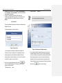
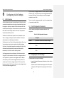
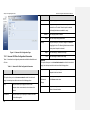
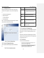
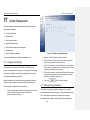
A login screen displays, as shown in Figure 3.4.
Figure 3.4 Login Screen
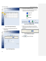
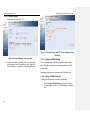
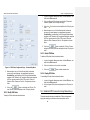
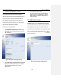
Figure 3.5 System Access Configuration Page
If you have problem connecting to the OfficeConnect Gigabit VPN
4. Click on Administration System Access menu to enter Account
configuration page as shown in Figure 3.5. Select an appropriate
account and change the password in the spaces provided if desired.
Firewall, you may want to check if your PC is configured to accept IP
address assignment from the OfficeConnect Gigabit VPN Firewall.
Another method is to set the IP address of your PC to any IP address in
When changing passwords, make sure you enter the existing login
the 192.168.1.0 network, such as 192.168.1.2.
password in the Old Password field, enter the new password in New
Password field and confirm the new password in Retype New Password
3. Enter your user name and password, and then click
enter the Configuration Manager. The first time you log into this
program, use these defaults:
Default User Name:
to
field and click
admin
15
button to save the change
OfficeConnect Gigabit VPN Firewall User’s Manual
Chapter 3. Quick Start Guide
Time Zone
drop-down
list
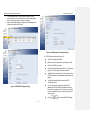
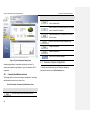
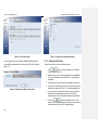
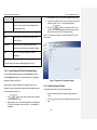
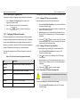
Figure 3.6 System Time Configuration Page
Figure 3.7 IP Setup Configuration Page
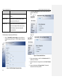
5. Click on Administration System Time menu and set the time zone
for the OfficeConnect Gigabit VPN Firewall by selecting your time
zone from the Time Zone drop-down list. Click
the settings.
to save
6. It is recommended that you keep the default LAN IP settings at this
point until after you have completed the rest of the configurations
and confirm that your Internet connection is working.
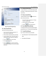
Figure 3.8 DHCP Server Configuration Page
16
OfficeConnect Gigabit VPN Firewall User’s Manual
Chapter 3. Quick Start Guide
7. It is recommended that you keep the default settings for DHCP
server until after you have completed the rest of the configurations
and confirm that your Internet connection is working.
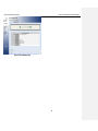
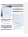
8. Click on Network IP Setup to configure the WAN settings for the
OfficeConnect Gigabit VPN Firewall.
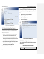
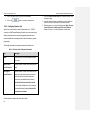
Figure 3.10 WAN Dynamic IP Configuration Page
a) PPPoE Connection Mode (see Figure 3.9)
Tick the Login Required checkbox.
Enter the user name and password provided by your ISP.
Click on the PPPoE radio button.
AC Name and Service Name are optional. You may leave it
empty if your ISP did not provide such information.
Tick the Disconnect checkbox if you want to disconnect the
PPPoE interface after the assigned idle timeout period has
elapsed.
Tick the Unnumbered checkbox to enable the PPP
unnumbered function.
You don’t need to enter primary/secondary DNS IP
addresses as PPPoE is able to automatically obtain this
information for you from your ISP. However, if you prefer to
use your favorite DNS servers, you may enter them in the
space provided.
Figure 3.9 WAN PPPoE Configuration Page
Click on
17
button to save the PPPoE settings.
OfficeConnect Gigabit VPN Firewall User’s Manual
Chapter 3. Quick Start Guide
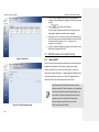
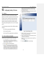
b) Dynamic IP Connection Mode (see Figure 3.10)
Enter WAN IP address in the IP Address field. This
information should be provided by your ISP.
Select the DHCP radio button to enable the DHCP function.
Enter IP Subnet Mask for the WAN. This information should
be provided by your ISP. Typically, it is 255.255.255.0.
You don’t need to enter primary/secondary DNS IP
addresses as DHCP client is able to automatically obtain this
information for you from your ISP. However, if you prefer to
use your favorite DNS servers, you may enter them in the
space provided.
Enter Gateway IP address provided by your ISP in the space
provided.
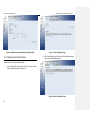
Enter at lease the primary DNS IP address provided by your
ISP. Secondary DNS IP address is optional. Enter it in the
space provided if you have such information from your ISP.
If you had previously registered a specific MAC address with
your ISP for Internet connections, enter the registered MAC
address here and make sure you check the MAC cloning
check box.
Click on
settings.
Click
to save the static IP settings
You have now completed customizing basic configuration settings. Read the
button to save the dynamic IP
following section to determine if you have access to the Internet.
3.4.2
Testing Your Setup
At this point, the OfficeConnect Gigabit VPN Firewall should enable any
computer on your LAN to use the OfficeConnect Gigabit VPN Firewall’s ADSL or
cable modem connection to access the Internet.
To test the Internet connection, open your web browser, and type the URL of
any external website (such as http://www.3com.com). The LED labeled WAN
should be blinking rapidly and may appear solid as the device connects to the
site. You should also be able to browse the web site through your web browser.
If the LEDs do not illuminate as expected or the web page does not display, see
Appendix 20 for troubleshooting suggestions.
3.4.3
Default Router Settings
In addition to handling the DSL connection to your ISP, the OfficeConnect
Gigabit VPN Firewall can provide a variety of services to your network. The
device is pre-configured with default settings for use with a typical home or small
office network.
Figure 3.11 WAN Static IP Configuration Page
c) Static IP Connection Mode
18
OfficeConnect Gigabit VPN Firewall User’s Manual
Chapter 3. Quick Start Guide
Table 3.2 lists some of the most important default settings; these and other
Option
features are described fully in the subsequent chapters. If you are familiar with
network configuration settings, review the settings in Table 3.2 to verify that they
Default Setting
Explanation/Instructions
LAN Port IP
Static IP address:
This is the IP address of the
Address
192.168.1.1
LAN port on the OfficeConnect
meet the needs of your network. Follow the instructions to change them if
necessary. If you are unfamiliar with these settings, try using the device without
subnet mask:
modification, or contact your ISP for assistance.
255.255.255.0
Gigabit VPN Firewall. The
LAN port connects the device
to your Ethernet network.
Before you modifying any settings, review Chapter 4 for general information
Typically, you will not need to
about accessing and using the Configuration Manager program. We strongly
change this address. See
recommend that you contact your ISP prior to changing the default configuration.
section 5.1 LAN IP Address for
instructions.
Table 3.2 Default Settings Summary
Option
Default Setting
Explanation/Instructions
DHCP (Dynamic
DHCP server enabled
The OfficeConnect Gigabit
Host Configuration
with the following pool
VPN Firewall maintains a pool
Protocol)
of addresses:
of private IP addresses for
192.168.1.2 through
192.168.1.254
dynamic assignment to your
LAN computers. To use this
service, you must have set up
your computers to accept IP
information dynamically, as
described in Part 2 of the
Quick Start Guide. See section
5.2 for an explanation of the
DHCP service.
19
OfficeConnect VPN Firewall User’s Manual
4
Chapter 4. Getting Started with the Configuration Manager
Getting Started with the
Configuration Manager
The OfficeConnect Gigabit VPN Firewall includes a preinstalled program called
the Configuration Manager, which provides an interface to the software installed
on the device. It enables you to configure the device settings to meet the needs
of your network. You access it through your web browser from any PC
Figure 4.1 Configuration Manager Login Screen
connected to the OfficeConnect Gigabit VPN Firewall via the LAN or WAN ports.
2. Enter your user name and password, and then click
This chapter describes the general guides for using the Configuration Manager.
4.1
.
The first time you log into the program, use these defaults:
Log into Configuration Manager
The Configuration Manager program is preinstalled on the OfficeConnect Gigabit
Default User Name:
admin
Default Password:
password
VPN Firewall. To access the program, you need the following:
A computer connected to the LAN or WAN port on the OfficeConnect
Gigabit VPN Firewall as described in the Quick Start Guide chapter.
4.2
Functional Layout
A web browser installed on the computer. The program is designed to work
Typical Configuration Manager page consists of two separate frames. The left
best with Microsoft Internet Explorer® 5.5, Netscape 7.0.2 or later.
frame, as shown in Figure 4.2, contains all the menus available for device
You may access the program from any computer connected to the
configuration. Related menus are grouped into categories, such as System,
OfficeConnect Gigabit VPN Firewall via the LAN or WAN ports. However, the
Network and etc. You can click on any of these to display a specific configuration
instructions provided here are for computers connected via the LAN ports.
page.
1. From a LAN computer, open your web browser, type the following in
the web address (or location) box, and press <Enter>:
http://192.168.1.1
This is the predefined IP address for the LAN port on the OfficeConnect
Gigabit VPN Firewall. A login screen displays, as shown in Figure 4.1.
21
OfficeConnect VPN Firewall User’s Manual
Chapter 4. Getting Started with the Configuration Manager
Button/Icon
Function
Discards any changes you have made and reverts all fields
back to the default value.
Adds a new item into the existing configuration, e.g. a static
route or a firewall ACL rule and etc.
Deletes the selected item, e.g. a static route or a firewall
ACL rule and etc.
Selects all items from the existing configuration page.
Enables a selected item.
Disables a selected item.
Logs out from Configuration Manager.
Figure 4.2 Typical Configuration Manager Page
A separate page displays in the right-hand-side frame for each menu. For
4.3
Overview of System Configuration
example, the configuration page displayed in Figure 4.2 is intended for DHCP
To view the overall system status, log into Configuration Manager as
configuration.
administrator, and then click the Device Summary menu.
4.2.1
Commonly Used Buttons and Icons
The following buttons or icons are used throughout the application. The following
table describes the function for each button or icon.
Table 4.1 Description of Commonly Used Buttons and Icons
Button/Icon
Function
Stores any changes you have made on the current page.
22
OfficeConnect VPN Firewall User’s Manual
Chapter 4. Getting Started with the Configuration Manager
Figure 4.3 Device Summary Page
23
OfficeConnect VPN Firewall User’s Manual
Chapter 5. Configuring LAN Settings
5.2.3 Configuring DHCP Server, but not for its own LAN port.
5
Configuring LAN Settings
5.1.1
LAN IP Configuration Parameters
Table 5.1describes the configuration parameters available for LAN IP
This chapter describes how to configure LAN properties for the LAN interface on
configuration.
the OfficeConnect Gigabit VPN Firewall that communicates with your LAN
Table 5.1 LAN IP Configuration Parameters
computers. You’ll learn to configure IP address, DHCP and DNS server for your
LAN in this chapter.
Setting
Description
5.1
IP Address
The LAN IP address of the OfficeConnect Gigabit VPN
LAN IP Address
Firewall. This IP is used by your computers to identify the
If you are using the OfficeConnect Gigabit VPN Firewall with multiple PCs on
OfficeConnect Gigabit VPN Firewall’s LAN port. Note that
your LAN, you must connect the LAN via the Ethernet ports on the built-in
the public IP address assigned to you by your ISP is not
Ethernet switch. You must assign a unique IP address to each device residing
your LAN IP address. The public IP address identifies the
on your LAN. The LAN IP address identifies the OfficeConnect Gigabit VPN
WAN port on the OfficeConnect Gigabit VPN Firewall to
Firewall as a node on your network; that is, its IP address must be in the same
the Internet.
subnet as the PCs on your LAN. The default LAN IP for the OfficeConnect
Subnet Mask
The LAN subnet mask identifies which parts of the LAN IP
Gigabit VPN Firewall is 192.168.1.1.
Address refer to your network as a whole and which parts
Definition
A network node can be thought of as any interface where a
refer specifically to nodes on the network. Your device is
device connects to the network, such as the OfficeConnect Gigabit
preconfigured with a default subnet mask of
VPN Firewall’s LAN port and the network interface cards on your
255.255.255.0.
PCs. See Appendix 18 for an explanation of subnets.
5.1.2
You can change the default to reflect the set of IP addresses that you want to
use with your network.
The OfficeConnect Gigabit VPN Firewall itself can function as a
Note
DHCP server for your LAN computers, as described in section
Configuring the LAN IP Address
Follow these steps to change the default LAN IP address.
1. Log into Configuration Manager as administrator, and then click
Network > IP Setup menu to display the Interface List Table as
shown in Figure 5.1.
2. Click on the
icon of the VLAN1/LAN entry to be modified in the
Interface List Table.
25
OfficeConnect VPN Firewall User’s Manual
Chapter 5. Configuring LAN Settings
3. In the IP Setup configuration page, enter a LAN IP address and
subnet mask for the OfficeConnect Gigabit VPN Firewall in the space
provided.
4. Click
to save the LAN IP address.
If you were using an Ethernet connection for the current session, and
changed the IP address, the connection will be terminated.
5. Reconfigure your PCs, if necessary, so that their IP addresses place
them in the same subnet as the new IP address of the LAN port. See
the Quick Start Guide chapter, ―Part 3 — Configuring Your
Computers,‖ for instructions.
6. Log into Configuration Manager by typing the new IP address in your
Web browser’s address/location box.
5.2
Figure 5.1 Interface List
5.2.1
DHCP (Dynamic Host Control Protocol)
What is DHCP?
DHCP is a protocol that enables network administrators to centrally manage the
assignment and distribution of IP information to computers on a network.
When you enable DHCP on a network, you allow a device — such as the
OfficeConnect Gigabit VPN Firewall — to assign temporary IP addresses to your
computers whenever they connect to your network. The assigning device is
called a DHCP server, and the receiving device is a DHCP client.
If you followed the Quick Start Guide instructions, you either
configured each LAN PC with an IP address, or you specified that
it will receive IP information dynamically (automatically). If you
chose to have the information assigned dynamically, then you
Note
configured your PCs as DHCP clients that will accept IP
addresses assigned from a DCHP server such as the
Figure 5.2 IP Setup Configuration Page
26
OfficeConnect Gigabit VPN Firewall.
OfficeConnect VPN Firewall User’s Manual
Chapter 5. Configuring LAN Settings
The DHCP server draws from a defined pool of IP addresses and ―leases‖ them
for a specified amount of time to your computers when they request an Internet
session. It monitors, collects, and redistributes the addresses as needed.
On a DHCP-enabled network, the IP information is assigned dynamically rather
than statically. A DHCP client can be assigned a different address from the pool
each time it reconnects to the network.
5.2.2
Why use DHCP?
DHCP allows you to manage and distribute IP addresses throughout your
network from the OfficeConnect Gigabit VPN Firewall. Without DHCP, you would
have to configure each computer separately with IP address and related
information. DHCP is commonly used with large networks and those that are
frequently expanded or otherwise updated.
5.2.3
Figure 5.3 DHCP Configuration Page
Configuring DHCP Server
By default, the OfficeConnect Gigabit VPN Firewall is configured
as a DHCP server on the LAN side, with a predefined IP address
pool of 192.168.1.10 through 192.168.1.42 (subnet mask
Note
255.255.255.0). To change this range of addresses, follow the
procedures described in this section.
2. Enter the information for the IP Address Pool (Begin/End Address),
Subnet Mask, Lease Time and Default Gateway IP Address, fields;
others, such as Primary/Secondary DNS Server IP Address and
Primary/Secondary WINS Server IP Address are optional. However,
it is recommended that you enter the primary DNS server IP address
in the space provided. You may enter the LAN IP or your ISP’s DNS
IP in the primary DNS Server IP Address field. Table 5.2 describes
the DHCP configuration parameters in detail.
Table 5.2 DHCP Configuration Parameters
First, you must configure your PCs to accept DHCP information assigned by a
DHCP server:
1. Log into Configuration Manager as administrator, click the LAN
menu, and then click the DHCP submenu. The DHCP Configuration
page displays as shown in Figure 5.3:
Field
Description
IP Address Pool Begin/End
Specify the lowest and highest
addresses in the DHCP address pool.
Subnet Mask
Enter the subnet mask to be used for the
DHCP address pool.
The amount of time the assigned
Lease Time
27
OfficeConnect VPN Firewall User’s Manual
Chapter 5. Configuring LAN Settings
Field
Description
Field
Description
address will be used by a device
connected on the LAN.
Default Gateway IP Address
The address of the default gateway for
servers are optional.
Primary/Secondary WINS
The IP address of the WINS servers to
Server IP Address (optional)
be used by computers that receive IP
computers that receive IP addresses
addresses from the DHCP IP address
from this pool. The default gateway is
pool. You don’t need to enter this
the device that the DHCP client
information unless your network has
computers first contacted to
WINS servers.
communicate with the Internet. Typically,
it is the OfficeConnect Gigabit VPN
Firewall’s LAN port IP address.
Primary/Secondary DNS Server
The IP address of the Domain Name
IP Address
System server to be used by computers
NBX Call Processor Options
If you have a 3Com NBX Call Processor
184
on your network, please enter its IP
address in this field.
Enable SIP Servers Options
To enable the SIP Servers Options 120,
120
please ensure that the enable checkbox
that receive IP addresses from this pool.
is ticked.
The DNS server translates common
Internet names that you type into your
SIP Server Encoding type
If the type of SIP server address is
web browser into their equivalent
FQDN, please click on FQDN radio
numeric IP addresses. Typically, the
button; otherwise, click on IP Address
server(s) are located with your ISP.
button.
However, you may enter LAN IP
The IP address or fully qualified domain
Primary SIP Address
address of the OfficeConnect Gigabit
VPN Firewall as it will serve as DNS
proxy for the LAN computers and
name of the Primary SIP Address.
Secondary SIP Address
The IP address or fully qualified domain
name of the Secondary SIP Address.
forward the DNS request from the LAN
to DNS servers and relay the results
back to the LAN computers. Note that
both the primary and secondary DNS
28
3. Click
to save the DHCP server configurations.
OfficeConnect VPN Firewall User’s Manual
5.2.4
Viewing Current DHCP Address Assignments
Chapter 5. Configuring LAN Settings
Import discovered LAN hosts as fixed DHCP entries: The local
When the OfficeConnect Gigabit VPN Firewall functions as a DHCP server for
network is scanned using ARP requests. The ARP scan will detect
your LAN, it keeps a record of any addresses it has leased to your computers.
active devices that are not DHCP clients. However, sometimes the name
To view a table of all current IP address assignments, just go to the DHCP Server
of the PC or device cannot be accurately determined, and will appear in
Configuration page. A page displays similar to that shown in Figure 5.3; the
the database as Unknown.
bottom half of the same page shows the existing DHCP address assignments.
5.3.1
The DHCP Server Address Table lists any IP addresses that are currently
To add a fixed DHCP Lease, follow these steps:
leased to LAN devices. For each leased address, the table lists the following
information:
Table 5.3 DHCP Address Assignment
Field
Description
MAC Address
A hardware ID of the device that leases an IP address
from the DHCP server.
Assigned IP
The address that has been leased from the pool.
Address
IP Address
Manually add a Fixed DHCP Lease.
1. Enter the name of the PC or device.
2. Enter the IP address of the PC or device. The DHCP Server will
permanently reserve the IP address for the specified device.
3. Enter the MAC address of the PC or device. Please note that the
MAC address format is six colon-separated pairs of hexadecimal
characters (0-9 and A-F), such as 00:0D:31:45:17:1B.
4. Click
5.3.2
button to add the new entry.
Import Discovered LAN Hosts as Fixed DHCP Entries
The following steps show you how to configure multiple DHCP entries by
importing discovered LAN hosts.
The time when the leased address is to be terminated.
Expired on
1. Click ―Import from Host Discovery‖ button. The host discovery
configuration page will be shown as Figure 5.4.
2. Select an appropriate interface from the Interface drop-down list.
5.3
Configuring Fixed DHCP Leases
3. Click ―Discovery‖ button to start the LAN host discovery.
4. The Host List table displays all discovered LAN hosts.
Fixed DHCP Leases are IP addresses assigned to hosts requiring permanent IP
settings. To configuring fixed DHCP Leases, you can follow one of the following
5. Click on the check box in front of the LAN host to be selected. Or
click ―Select All‖ button to select all discovered entries.
methods:
6. Click on the check box of ―Fixed DHCP Lease‖ and then click
to save the settings.
Manually enter fixed DHCP entry: You can manually enter information
about a network device.
29
OfficeConnect VPN Firewall User’s Manual
Chapter 5. Configuring LAN Settings
5.4.2
Assigning DNS Addresses
Multiple DNS addresses are useful to provide alternatives when one of the
servers is down or is encountering heavy traffic. ISPs typically provide primary
and secondary DNS addresses, and may provide additional addresses. Your
LAN PCs learn these DNS addresses in one of the following ways:
Statically: If your ISP provides you with their DNS server addresses, you
can assign them to each PC by modifying the PCs' IP properties.
Dynamically from a DHCP pool: You can configure the DHCP Server the
OfficeConnect Gigabit VPN Firewall and create an address pool that
specify the DNS addresses to be distributed to the PCs. Refer to the
section Configuring DHCP Server on page 27 for instructions on creating
DHCP address pools.
Figure 5.4 Host Discovery Configuration Page
5.4
5.4.1
DNS
About DNS
Domain Name System (DNS) servers map the user-friendly domain names that
In either case, you can specify the actual addresses of the ISP's DNS servers
(on the PC or in the DHCP pool), or you can specify the address of the LAN port
on the OfficeConnect Gigabit VPN Firewall (e.g., 192.168.1.1). When you
specify the LAN port IP address, the device performs DNS relay, as described in
the following section.
users type into their Web browsers (e.g., "yahoo.com") to the equivalent
If you specify the actual DNS addresses on the PCs or in the
numerical IP addresses that are used for Internet routing.
When a PC user types a domain name into a browser, the PC must first send a
Note
DHCP pool, the DNS relay feature is not used.
request to a DNS server to obtain the equivalent IP address. The DNS server will
attempt to look up the domain name in its own database, and will communicate
5.4.3
Configuring DNS Relay
with higher-level DNS servers when the name cannot be found locally. When the
When you specify the device's LAN port IP address as the DNS address, then
address is found, it is sent back to the requesting PC and is referenced in IP
the OfficeConnect Gigabit VPN Firewall automatically performs ―DNS relay‖; i.e.,
packets for the remainder of the communication.
because the device itself is not a DNS server, it forwards domain name lookup
requests from the LAN PCs to a DNS server at the ISP. It then relays the DNS
server’s response to the PC.
30
OfficeConnect VPN Firewall User’s Manual
Chapter 5. Configuring LAN Settings
When performing DNS relay, the OfficeConnect Gigabit VPN Firewall must
address.
maintain the IP addresses of the DNS servers it contacts. It can learn these
addresses in either or both of the following ways:
Learned through PPPoE or Dynamic IP Connection: If the
OfficeConnect Gigabit VPN Firewall uses a PPPoE (see section 8.2.2
5.5
Configuring the Port Settings
Configuring PPPoE for WAN) or Dynamic IP (see section 8.4.2 Configuring
Dynamic IP for WAN) connection to the ISP, the primary and secondary
DNS addresses can be learned via the PPPoE protocol. Using this option
This page allows you to enable/disable a specific port, change the port speed or
enable/disable DMZ ports. Follow these steps to configure the port settings:
provides the advantage that you will not need to reconfigure the PCs or the
OfficeConnect Gigabit VPN Firewall if the ISP changes their DNS
addresses.
Configured on the OfficeConnect Gigabit VPN Firewall: You can also
specify the ISP's DNS addresses in the WAN Configuration page as
shown in
Follow these steps to configure DNS relay:
1. Enter LAN IP in the DNS Server IP Address field in DHCP
configuration page as shown in Figure 5.3.
2. Configure the LAN PCs to use the IP addresses assigned by the
DHCP server on the OfficeConnect Gigabit VPN Firewall, or enter
the OfficeConnect Gigabit VPN Firewall's LAN IP address as their
DNS server address manually for each PC on your LAN.
Figure 5.5 Port Setup Configuration Page
DNS addresses that are assigned to LAN PCs prior to enabling
DNS relay will remain in effect until the PC is rebooted. DNS relay
To configure the port settings, click ―Network‖ in the main menu and then click
will only take effect when a PC's DNS address is the LAN IP
―Port Setup‖ sub-menu. See Figure 5.5 Port Setup Configuration Page.
address.
Note
Similarly, if after enabling DNS relay, you specify a DNS address
1. Move the mouse cursor to the desired port icon and then click on the
icon to configure the selected port. See Figure 5.6 Port Selection.
(other than the LAN IP address) in a DHCP pool or statically on a
PC, then that address will be used instead of the DNS relay
31
OfficeConnect VPN Firewall User’s Manual
Chapter 5. Configuring LAN Settings
Figure 5.6 Port Selection
2. If the selected port is Port 3 or Port 4, you should be able to change
the mode of selected port to LAN port or DMZ port. Select the port
type from the drop-down list. Once the DMZ port is enabled, the
corresponding DMZ interface will be activated as well and you
should be able to configure the DMZ interface in the IP Setup
configuration page.
3. To enable the selected port, please keep the Enable check box
checked. Otherwise, please click on the Enable check box to disable
the selected port.
4. To change the selected port speed, please select a value from the
Speed drop-down list.
5. Click.
5.6
to save the settings you made.
Viewing LAN Statistics
You can view statistics of your LAN traffic on the OfficeConnect Gigabit VPN
Firewall. You will not typically need to view this data, but you may find it helpful
when working with your ISP to diagnose network and Internet data transmission
problems.
To view LAN IP statistics, click Traffic Statistics in the Monitoring submenu and
select VLAN/LAN (eth0.1) from the interface drop down button. Figure 5.7 shows
the LAN Statistics page:
32
Figure 5.7 LAN Statistics Page
OfficeConnect VPN Firewall User’s Manual
Chapter 5. Configuring LAN Settings
A port can only be an untagged member of one VLAN. By default it is untagged
6
Configuring VLAN Settings
member of VLAN1. The system cannot remove its untagged membership from
the present VLAN directly, it has to add the port as one of the untagged
membership in a new VLAN.
6.1
VLAN Overview
VLANs are logical subgroups with a Local Area Network (LAN) which combine
There is no restriction on tagged membership. A port can be a tagged member
of any number of multiple VLANs.
user stations and network devices into a single unit, regardless of the physical
LAN segment to which they are attached. VLANs allow network traffic to flow
more efficiently within subgroups. VLANs use software to reduce the amount of
time it takes for network changes, additions, and moves to be implemented.
6.2
VLAN Configuration Parameters
Table 6.1 describes the configuration parameters available for VLAN
configuration.
VLANs restrict traffic within the VLAN.
Table 6.1 VLAN Configuration Parameters
VLANs have no minimum number of ports, and can be created per unit, per
device, or through any other logical connection combination, since they are
software-based and not defined by physical attributes.
VLANs function at Layer 2. Since VLANs isolate traffic within the VLAN, a Layer
3 router working at a protocol level is required to allow traffic flow between
Setting
Description
VLAN ID
Specifies the VLAN ID to which the port is assigned.
Tag Port
Specifies a physical port to be a tagged member of a
VLAN.
VLANs. Layer 3 routers identify segments and coordinate with VLANs. VLANs
are Broadcast and Multicast domains. Broadcast and Multicast traffic is
Untag Port
Specifies a physical port to be a untagged member of a
transmitted only in the VLAN in which the traffic is generated.
VLAN.
VLAN tagging provides a method of transferring VLAN information between
VLAN groups. VLAN1is the default VLAN. All ports are untagged members of
VLAN1 by default. If any port becomes an untagged member of a different
6.3
Configuring the VLAN settings
Follow these steps to change the VLAN settings.
VLAN, then the port is removed from untagged membership of VLAN1. For
example: If port 24 is made an untagged member of VLAN 5, the port will no
longer be a member of VLAN1. However, if the port is made an tagged member
of VLAN5, it still remains untagged in VLAN1.
1. Log into Configuration Manager as administrator, and then click the
Network menu.
When the submenus of Network menu displays, clicks VLAN submenu
to display the VLAN configuration summary page as shown in Figure
6.1.
33
OfficeConnect VPN Firewall User’s Manual
Chapter 5. Configuring LAN Settings
7. Enter a valid ID into the specified VLAN ID field.
8. Move the mouse cursor to the desired VLAN membership type icon
and click on the icon to select the membership type.
Untagged VLAN
Tagged VLAN
Not A Member
Figure 6.3 Select a VLAN Membership Type
Figure 6.1 VLAN Configuration Summary Page
6. Click on the Pan icon of the desired VLAN to enter the VLAN
Configuration page.
9. Move the mouse cursor to the desired port icon and click on the
RJ45 icon to apply the membership type to the selected port. Please
see Figure 6.4.
Figure 6.4 VLAN Membership assignment
10. Click.
Figure 6.2 VLAN Configuration Page
34
to save the LAN IP address.
OfficeConnect VPN Firewall User’s Manual
7
Configuring Spanning Tree
Settings
7.1
Spanning Tree Overview
Chapter 5. Configuring LAN Settings
7.2
Spanning Tree Configuration Parameters
Table 7.1 describes the configuration parameters available for VLAN
configuration.
Table 7.1 Spanning Tree Configuration Parameters
This section contains information for configuring STP. The Spanning Tree
Protocol (STP) provides tree topography for any arrangement of bridges. STP
also provides a single path between end stations on a network, eliminating
Setting
Description
System Priority
Specifies the bridge priority value. When switches or
loops.
bridges are running STP, each is assigned a priority.
Loops occur when alternate routes exist between hosts. Loops in an extended
After exchanging BPDUs, the device with the lowest
network can cause bridges to forward traffic indefinitely, resulting in increased
priority value be comes the Root Bridge. The field
traffic and reducing network efficiency.
range is 0-61440. The default value is 32768. The port
While Classic STP prevents Layer 2 forwarding loops in a general network
priority value is provided in increments of 4096.
topology, convergence can take between 30-60 seconds. Rapid Spanning Tree
Hello Time
Specifies the device Hello Time. The Hello Time
Protocol (RSTP) detects and uses network topologies that allow a faster STP
indicates the amount of time in seconds a Root Bridge
convergence without creating forwarding loops.
waits between configuration messages. The default is 2
The device supports the following STP versions:
seconds.
Classic STP — Provide a single path between end stations, avoiding and
Max Age
Specifies the device Maximum Age Time. The
eliminating loops.
Maximum Age Time is the amount of time in seconds a
Rapid STP — Detect and use network topologies that provide faster
bridge waits before sending configuration messages.
convergence of the spanning tree, without creating forwarding loops. While
The default Maximum Age Time is 20 seconds.
Classic STP prevents Layer 2 forwarding loops in a general network
Forward Delay
topology, convergence can take between 30-60 seconds. Rapid Spanning
Specifies the device Forward Delay Time. The Forward
Delay Time is the amount of time in seconds a bridge
Tree Protocol (RSTP) detects and uses network topologies that allow a
remains in a listening and learning state before
faster STP convergence without creating forwarding loops.
forwarding packets. The default is 15 seconds.
35
OfficeConnect VPN Firewall User’s Manual
Chapter 5. Configuring LAN Settings
Force Version
Specifies the STP version to run on the device. The
When the submenus of Network menu displays, clicks on Spanning
possible values are:
Tree submenu to display the Spanning Tree Configuration page as
Normal – RTSP mode only
shown in Figure 7.1.
Compatible – STP compatible mode
Per-port settings
Enable
Indicates that STP or RSTP is enabled on the port.
Edge
Indicates if Edge Port is enabled on the port. If Edge
Port is enabled for a port, the Port State is
automatically placed in the Forwarding state when the
port link is up. Edge Port optimizes the STP protocol
convergence. STP convergence takes 30 seconds and
is not dependent on the number of switches in the
network. However, an edge port that receives a BPDU
immediately loses edge port status and becomes a
normal spanning tree port.
Path Cost
Indicates the port contribution to the root path cost. The
path cost is adjusted to a higher or lower value, and is
used to forward traffic when a path is re-routed.
Figure 7.1 Spanning Tree Configuration Page
2. Enter the bridge priority value into the System Priority field. Please
see Table 7.1 for more detail description.
3. Enter the Hello Time value in the specified field. The Hello Time
indicates the amount of time in seconds a Root Bridge waits between
configuration messages.
4. Enter the Max Age Time value in the specified field. Please note that
the default value is 20 seconds.
7.3
Configuring the Spanning Tree settings
Follow these steps to change the Spanning Tree settings.
1. Log into Configuration Manager as administrator, and then click the
Network menu.
36
5. Enter the Forward Delay Time value in the specified field. Please
note that the default value if 15 seconds.
6. Select an appropriate STP version from the Force Version dropdown list.
7. Go to the RSTP Configuration List. Click on the Enable button to
enable the Spanning Tree function on the specified port. If this port is
also an edge port, click on the Edge button.
OfficeConnect VPN Firewall User’s Manual
Chapter 5. Configuring LAN Settings
8. Enter the path code in the space provided to indicate the port
contribute to the root path cost.
9. Click.
7.4
to save the LAN IP address.
Viewing the Spanning Tree Status
To display the port status of Spanning Tree, log into Configuration Manager as
administrator, click on the Network menu and Spanning Tree submenu, and then
click on the Status tab button (See Figure 7.2 RSTP/STP Status Page ).
Figure 7.2 RSTP/STP Status Page
37
OfficeConnect VPN Firewall User’s Manual
Chapter 8. Configuring WAN Settings
Figure 8.1 WAN Connection Type Configuration
8
Configuring WAN Settings
8.2
PPPoE
This chapter describes how to configure WAN settings for the WAN interface on
8.2.1
the OfficeConnect Gigabit VPN Firewall that communicates with your ISP. You’ll
WAN PPPoE Configuration Parameters
Table 8.1 describes the configuration parameters available for PPPoE
learn to configure IP address, DHCP and DNS server for your WAN in this
connection mode.
chapter.
8.1
Table 8.1 WAN PPPoE Configuration Parameters
WAN Connection Mode
Setting
Description
Three modes of WAN connection are supported by the OfficeConnect Gigabit
User Name and
Enter the username and password you use to log into
VPN Firewall – PPPoE, PPTP, Telstra BigPond, dynamic IP and static IP. If your
Password
your ISP. (Note: this is different from the information you
used to log into Configuration Manager.)
WAN connection requires a login, please make the ―Login Required‖ checkbox
checked as shown in Figure 8.1.
AC Name
If your ISP requires PPPoE AC Name, please enter the
(Optional)
valid AC name into this field. Leave this field blank if it is
not necessary.
Connection
Service Name
If your ISP requires Service Name, please enter the valid
Mode
Service name into this field. Leave this field blank if it is
not necessary.
39
OfficeConnect VPN Firewall User’s Manual
Chapter 8. Configuring WAN Settings
Setting
―Use These DNS Servers‖ radio button and enter IP addresses for
the primary and secondary DNS servers.
Description
Dial On Demand
Enter the inactivity timeout period at which you want to
disconnect the Internet connection when there is no
traffic. The minimum value of inactivity timeout is 30
seconds. RIP and SNTP services may interfere with this
function if there are activities from these two services.
Make sure that the update interval setting of the system
6. Choose a connection option and enter appropriate setting if desired.
The default setting is ―Disable‖.
7. Click
to save the PPPoE settings when you are done
with the configuration. You’ll see a summary of the WAN
configuration at the bottom half of the configuration page. Note that if
the default gateway address is not shown immediately, click on the
WAN menu to open the WAN configuration page again.
date and time (in the System Management / Date/Time
Setup configuration page – see 17.5 Setup Date and
Time for details) is greater than the inactivity timeout
value.
Unnumbered
8.3
PPTP
8.3.1
WAN PPTP Configuration Parameters
Table 8.2 WAN PPTP Configuration Parameters
If your ISP assigned a block of IP addresses, you would
select ―Enable‖ radio button to give your PPPoE interface
Setting
Description
User Name and
Enter the username and password you use to log into
Password
your ISP. (Note: this is different from the information you
an IP address from the same range assigned to your
LAN. Otherwise, select ―Disable‖.
8.2.2
Configuring PPPoE for WAN
Follow the instructions below to configure PPPoE settings:
used to log into Configuration Manager.)
Service Name
1. Please make the ―Login Required‖ checkbox checked as shown in
Figure 8.1
2. If you are connecting to the Internet using PPPoE, you probably only
have to enter User Name and Password in the PPPoE Configuration
page as shown in Figure 8.1 unless you want to use your preferred
DNS servers.
3. (Optional) Enter AC name in the space provided if required by your
ISP. Otherwise, please leave this field blank.
Service name into this field. Leave this field blank if it is
not necessary.
PPTP Server IP
40
IP Address of the PPTP server.
Address
Interface IP
IP Address assigned by your ISP to make the connection
Address
with the PPTP server.
4. (Optional) Enter Service name in the space provided if required by
your ISP. Otherwise, please leave this field blank.
5. (Optional) If you like to use DNS setting provided by your ISP, please
select ―Get Automatically from ISP‖ radio button. Otherwise, select
If your ISP requires Service Name, please enter the valid
8.3.2
Configuring PPTP for WAN
Follow the instructions below to configure PPPoE settings:
OfficeConnect VPN Firewall User’s Manual
1. Please make the ―Login Required‖ checkbox checked as shown in
Figure 8.1.
2. If you are connecting to the Internet using PPTP, you have to enter
User Name and Password in the specified fields.
Chapter 8. Configuring WAN Settings
Field
Description
Primary/
IP address of the primary and/or secondary DNS are
Secondary DNS
optional as DHCP client will automatically obtain the DNS
3. Enter a valid PPTP IP address in the PPTP Server IP Address field.
IP addresses configured at your ISP. However, if there
4. If the IP address of WAN interface is automatically assigned by your
ISP, select ―DHCP‖ radio button in the Connection Mode field.
Otherwise, select ―Static IP Address‖ button and enter valid IP
address, Subnet mask and Gateway IP address in the specified
fields.
are other DNS servers you would rather use, enter the IP
addresses in the spaces provided.
MAC Cloning
The default is to use the MAC address of the WAN
interface. However, if you had registered a MAC address
5. (Optional) If you like to use DNS setting provided by your ISP, please
select ―Get Automatically from ISP‖ radio button. Otherwise, select
―Use These DNS Servers‖ radio button and enter IP addresses for
the primary and secondary DNS servers.
6. Click
to save the PPTP settings when you are done
with the configuration. You’ll see a summary of the WAN
configuration at the bottom half of the configuration page. Note that if
the default gateway address is not shown immediately, click on the
WAN menu to open the WAN configuration page again.
8.4
8.4.1
Dynamic IP
WAN Dynamic IP Configuration Parameters
Table 8.3 describes the configuration parameters available for dynamic IP
connection mode.
Table 8.3 WAN Dynamic IP Configuration Parameters
Field
Description
previously with your ISP, you may need to enter that MAC
address here.
8.4.2
Configuring Dynamic IP for WAN
Follow the instructions below to configure dynamic IP settings:
1. Please make the ―Login Required‖ checkbox unchecked as shown in
Figure 8.1.
2. (Optional) If you want to manually enter the DNS servers, please
click ―Use These DNS Servers‖ radio button and enter the IP
addresses for the primary and secondary DNS servers if you want to
use your preferred DNS servers; otherwise, skip this step.
3. If you had previously registered a specific MAC address with your
ISP for Internet access, click ―Use this MAC Addresse‖ radio button
and enter the registered MAC address here and make sure you
check the MAC cloning check box.
4. Click
to save the Dynamic IP settings when you are
done with the configuration. You’ll see a summary of the WAN
configuration at the bottom half of the configuration page. Note that if
the default gateway address is not shown immediately, click on the
WAN menu to open the WAN configuration page again.
41
OfficeConnect VPN Firewall User’s Manual
Chapter 8. Configuring WAN Settings
Setting
Description
Gateway IP
Gateway IP address provided by your ISP. It must be in
Address
the same subnet as the WAN on the OfficeConnect
Gigabit VPN Firewall.
Primary/
You must at least enter the IP address of the primary
Secondary DNS
DNS server. Secondary DNS is optional
8.5.2
Configuring Static IP for WAN
Figure 8.2 WAN Dynamic IP (DHCP client) Configuration Page
8.5
8.5.1
Static IP
WAN Static IP Configuration Parameters
Table 8.4 describes the configuration parameters available for static IP
connection mode.
Table 8.4 WAN Static IP Configuration Parameters
Setting
Description
IP Address
WAN IP address provided by your ISP.
IP Subnet Mask
WAN subnet mask provided by your ISP. Typically, it is
Figure 8.3 WAN Static IP Configuration Page
Follow the instructions below to configure static IP settings:
set as 255.255.255.0.
1. Select Static from the Connection Mode drop-down list as shown in
Figure 8.3.
42
OfficeConnect VPN Firewall User’s Manual
Chapter 8. Configuring WAN Settings
2. Enter WAN IP address in the IP Address field. This information
should be provided by your ISP.
3. Enter Subnet Mask for the WAN. This information should be
provided by your ISP. Typically, it is 255.255.255.0.
4. Enter gateway address provided by your ISP in the space provided.
5. Enter the IP address of the primary DNS server. This information
should be provided by your ISP. Secondary DNS server is optional.
6. Click
to save the static IP settings when you are done
with the configuration. You’ll see a summary of the WAN
configuration at the bottom half of the configuration page.
8.6
Viewing WAN Statistics
You can view statistics of your WAN traffic. You will not typically need to view
this data, but you may find it helpful when working with your ISP to diagnose
Figure 8.4 WAN Statistics Page
network and Internet data transmission problems.
To view WAN IP statistics, click Status on the menu. Figure 8.4 shows the WAN
Statistics page:
43
OfficeConnect VPN Firewall User’s Manual
Chapter 9. Configuring Routes
default gateway is assigned automatically by your ISP whenever the
9
Configuring Routes
You can use Configuration Manager to define specific routes for your Internet
and network data communication. This chapter describes basic routing concepts
and provides instructions for creating routes.
device negotiates an Internet connection. (The process for adding a default
route is described in section 9.3.2 Adding Static Routes.)
You may need to define routes if your home setup includes two or more
networks or subnets, if you connect to two or more ISP services, or if you
connect to a remote corporate LAN.
Note that most users do not need to define routes.
9.1
Overview of IP Routes
The essential challenge of a router is: when it receives data intended for a
particular destination, which next device should it send that data to? When you
define IP routes, you provide the rules that the OfficeConnect Gigabit VPN
Firewall uses to make these decisions.
9.1.1
Do I need to define IP routes?
Most users do not need to define IP routes. On a typical small home or office
LAN, the existing routes that set up the default gateways for your LAN
computers and for the OfficeConnect Gigabit VPN Firewall provide the most
appropriate path for all your Internet traffic.
On your LAN computers, a default gateway directs all Internet traffic to the
LAN port on the OfficeConnect Gigabit VPN Firewall. Your LAN computers
know their default gateway either because you assigned it to them when
Figure 9.1 Routing Configuration Page
9.2 Dynamic Routing using RIP (Routing Information
Protocol)
you modified their TCP/IP properties, or because you configured them to
RIP enables routing information exchange between routers; thus, routes are
receive the information dynamically from a server whenever they access
updated automatically without human intervention. It is recommended that you
the Internet. (Each of these processes is described in the Quick Start
enable RIP in the System Services Configuration Page as shown in Figure 9.2.
Guide instructions, Part 2.)
On the OfficeConnect Gigabit VPN Firewall itself, a default gateway is
defined to direct all outbound Internet traffic to a router at your ISP. This
45
OfficeConnect VPN Firewall User’s Manual
Chapter 9. Configuring Routes
9.3
Static Routing
9.3.1
Static Route Configuration Parameters
The following table defines the available configuration parameters for static
routing configuration.
Table 9.1 Static Route Configuration Parameters
Field
Description
Route Name
Specifies route name for a specific static route entry.
Destination
Specifies the IP address of the destination computer or
Address
an entire destination network. It can also be specified as
all zeros to indicate that this route should be used for all
Figure 9.2 RIP Configuration Page
9.2.1
destinations for which no other route is defined (this is the
route that creates the default gateway). Note that
Enabling/Disabling RIP
destination IP must be a network ID. The default route
Follow these instructions to enable or disable RIP:
uses a destination IP of 0.0.0.0. Refer to Appendix 18 for
1. Click Network Routing submenu and click ―RIP‖ tab, click the ―Yes‖
or ―No‖ radio button in ―Enable RIP‖ field depending on whether you
want to enable or disable RIP.
an explanation of network ID.
Subnet Mask
Indicates which parts of the destination address refer to
2. Select RIPv1 or RIPv2 from the ―RIP Version‖ drop-down list.
the network and which parts refer to a computer on the
3. If automatic route summarization is required, click ―Auto-Summary‖
option box.
network. Refer to Appendix 18, for an explanation of
4. If authentication for RIPv2 is required, select ―Yes‖ button in the
Authentication field and enter ―First Key Parameters‖ and ―Second
Key Parameters‖ in the specified fields.
0.0.0.0.
5. Click
network masks. The default route uses a netmask of
Private
Select Private if this static route entry will not be
advertised in RIP.
to enable or disable RIP.
Interface
Specifies the interface which is the physical network
interface through which route is accessible.
46
OfficeConnect VPN Firewall User’s Manual
Field
Description
Gateway IP
Gateway IP address
Chapter 9. Configuring Routes
9.3.4
Viewing the Static Routing Table
All IP-enabled computers and routers maintain a table of IP addresses that are
commonly accessed by their users. For each of these destination IP addresses,
Address
the table lists the IP address of the first hop the data should take. This table is
known as the device’s routing table.
9.3.2
Adding Static Routes
Follow these instructions to add a static route to the routing table.
1. Click Network Routing submenu to enter the Static Routes
Configuration page.
2. Click
button to enter Add Static Route page.
3. Enter a route name for this static route in the Route Name field.
4. If you want to advertise this static route in RIP, please do not check
―Private‖ button.
5. Enter the Destination Address, Subnet Mask and Gateway IP
Address to the specified field.
6. Select a interface from the Interface drop-down list.
7. Click
9.3.3
to add a new route.
Deleting Static Routes
Figure 9.3 Viewing Routing Table
Follow these instructions to delete a static route from the routing table.
1. Click Network Routing submenu to enter the Static Routes
Configuration page
2. Click on the check box in front of the rule to be selected.
3. Click
to delete the selected route entries.
Do not remove the route for default gateway unless you know
what you are doing. Removing the default route will render the
WARNING
Internet unreachable.
47
OfficeConnect VPN Firewall User’s Manual
10
Chapter 10. Configuring DDNS
Configuring DDNS
Internet
Dynamic DNS is a service that allows computers to use the same domain name,
HTTP DDNS Server
(DynDNS, TokyoDNS)
even when the IP address changes from time to time (during reboot or when the
ISP's DHCP server resets IP leases). OfficeConnect Gigabit VPN Firewall
DynDNS
sl1000.homeunix.com
connects to a Dynamic DNS service whenever the WAN IP address changes. It
ISR
supports setting up the web services such as Web server, FTP server using a
TokyoDNS
sl1000.dns-tokyo.jp
domain name instead of the IP address. Dynamic DNS supports the DDNS
clients with the following features:
Update DNS records (addition) when an external interface comes up
Any interface status change to an external interface sends a DDNS update to
the DDNS service provider.
Dynamic DNS Client
DDNS client uses the mechanism provided by the popular DDNS service
Figure 10.1 Network Diagram for HTTP DDNS
providers for updating the DNS records dynamically. In this case, the service
Whenever IP address of the configured DDNS interface changes, DDNS update
provider updates DNS records in the DNS. OfficeConnect Gigabit VPN Firewall
is sent to the specified DDNS service provider. OfficeConnect Gigabit VPN
uses HTTP to trigger this update.
Firewall should be configured with the DDNS username and password that are
The OfficeConnect Gigabit VPN Firewall supports HTTP DDNS update with the
following service providers:
DynDNS.org
TZO.com
Oray.net
DtDNS.com
3322.org
obtained from the DDNS service provider.
10.1 DDNS Configuration Parameters
Table 10.1 describes the configuration parameters available for DDNS service.
Table 10.1 DDNS Configuration Parameters
Field
Description
49
OfficeConnect VPN Firewall User’s Manual
Chapter 10. Configuring DDNS
Field
Description
Choose WAN
Interface
Specifies an interface to be used for the DDNS update.
10.3 Configuring HTTP DDNS Client
Select DDNS Service
DynDNS
Please visit http://www.dyndns.org for more details.
TZO.com
Please visit http://www.tzo.com for more details.
Oray.net
Please visit http://www.oray.cn for more details.
DtDNS.com
3322.org
Registered Domain
Please visit http://www.dtdns.com for more details.
Please visit http://www.3322.com for more details
Enter the registered domain name in the specified field
Name
Account
Enter the username provided by your DDNS service
Figure 10.2 HTTP DDNS Configuration Page
provider in the specified field.
Follow these instructions to configure the HTTP DDNS:
Password
Enter the password provided by your DDNS service
provider in the specified field.
1. First, you should have already registered a domain name to the
DDNS service provider. If you have not done so, please visit
www.dyndns.org or www.tzo.com for more details.
10.2 Access DDNS Configuration Page
2. Click Network DDNS submenu to open the DDNS configuration
page.
Log into Configuration Manager as admin, and then click the DDNS menu. The
3. Select a DDNS service provider from radio buttons.
DDNS Configuration page displays, as shown in Figure 10.2.
4. Enter the registered domain name, username and password in the
specified fields.
Note that when you open the DDNS Configuration page, a list of existing DDNS
5. Open the DDNS Configuration page (see section 10.2)
configuration is displayed at the bottom half of the configuration page such as
those shown in Figure 10.2.
50
6. Click on
button to send a DNS update request to your
DDNS service provider. Note that DNS update request will also be
sent to your DDNS Service provider automatically whenever the
WAN port status is changed.
OfficeConnect VPN Firewall User’s Manual
11
Chapter 11. Configuring Firewall/NAT Settings
11.1 Firewall Overview
Configuring Firewall/NAT
Settings
11.1.1 Stateful Packet Inspection
The stateful packet inspection engine in the OfficeConnect Gigabit VPN Firewall
maintains a state table that is used to keep track of connection states of all the
The OfficeConnect Gigabit VPN Firewall provides built-in firewall/NAT functions,
packets passing through the firewall. The firewall will open a ―hole‖ to allow the
enabling you to protect the system against denial of service (DoS) attacks and
packet to pass through if the state of the packet that belongs to an already
other types of malicious accesses to your LAN while providing Internet access
established connection matches the state maintained by the stateful packet
sharing at the same time. You can also specify how to monitor attempted
inspection engine. Otherwise, the packet will be dropped. This ―hole‖ will be
attacks, and who should be automatically notified.
closed when the connection session terminates. No configuration is required for
This chapter describes how to create/modify/delete ACL (Access Control List)
rules to control the data passing through your network. You will use firewall
stateful packet inspection and please note that the firewall service is enabled by
default.
configuration pages to:
11.1.2 DoS (Denial of Service) Protection
Create, modify, delete and view inbound/outbound ACL rules.
Both DoS protection and stateful packet inspection provide first line of defense
Create, modify and delete pre-defined services, IP pools, NAT pools,
application filters and Schedules to be used in inbound/outbound ACL
configurations.
View firewall statistics.
Note: When you define an ACL rule, you instruct the OfficeConnect Gigabit VPN
Firewall to examine each data packet it receives to determine whether it meets
criteria set forth in the rule. The criteria can include the network or internet
protocol it is carrying, the direction in which it is traveling (for example, from the
LAN to the Internet or vice versa), the IP address of the sending computer, the
destination IP address, and other characteristics of the packet data.
for your network. No configuration is required for both protections on your
network as long as firewall is enabled for the OfficeConnect Gigabit VPN Firewall.
By default, the firewall is enabled at the factory.
11.1.3 Firewall and Access Control List (ACL)
11.1.3.1 Priority Order of ACL Rule
All ACL rules have a rule ID assigned – the smaller the rule ID, the higher the
priority. Firewall monitors the traffic by extracting header information from the
packet and then either drops or forwards the packet by looking for a match in the
ACL rule table based on the header information. Note that the ACL rule checking
starts from the rule with the smallest rule ID until a match is found or all the ACL
rules are examined. If no match is found, the packet is dropped; otherwise, the
If the packet matches the criteria established in a rule, the packet can either be
accepted (forwarded towards its destination), or denied (discarded), depending
packet is either dropped or forwarded based on the action defined in the
matched ACL rule.
on the action specified in the rule.
51
OfficeConnect Gigabit VPN Firewall User’s Manual
Chapter 14 Configuring IPSec VPN
11.1.3.2 Tracking Connection State
11.2 NAT Overview
The stateful inspection engine in the firewall keeps track of the state, or progress,
of a network connection. By storing information about each connection in a state
table, OfficeConnect Gigabit VPN Firewall is able to quickly determine if a packet
passing through the firewall belongs to an already established connection. If it
does, it is passed through the firewall without going through ACL rule evaluation.
Network Address Translation allows use of a single device, such as the
OfficeConnect Gigabit VPN Firewall, to act as an agent between the Internet
(public network) and a local (private) network. This means that a NAT IP address
can represent an entire group of computers to any entity outside a network.
Network Address Translation (NAT) is a mechanism for conserving registered IP
For example, an ACL rule allows outbound ICMP packet from 192.168.1.1 to
192.168.2.1. When 192.168.1.1 sends an ICMP echo request (i.e. a ping packet)
to 192.168.2.1, 192.168.2.1 will send an ICMP echo reply to 192.168.1.1. In the
OfficeConnect Gigabit VPN Firewall, you don’t need to create another inbound
addresses in large networks and simplifying IP addressing management tasks.
Because of the translation of IP addresses, NAT also conceals true network
address from privy eyes and provide a certain degree security to the local
network.
ACL rule because stateful packet inspection engine will remember the
connection state and allows the ICMP echo reply to pass through the firewall
The NAT modes supported are static NAT, dynamic NAT, NAPT, reverse static
NAT and reverse NAPT.
11.1.4 Default ACL Rules
The OfficeConnect Gigabit VPN Firewall supports three types of default access
Static NAT maps an internal host address to a globally valid Internet address
rules:
(one-to-one). The IP address in each packet is directly translated with a globally
Inbound Access Rules: for controlling incoming access to computers on
your LAN.
valid IP contained in the mapping. Figure 11.1 illustrates the IP address mapping
relationship between the three private IP addresses and the three globally valid
Outbound Access Rules: for controlling outbound access to external
IP addresses. Note that this mapping is static, i.e. the mapping will not change
networks for hosts on your LAN.
over time until this mapping is manually changed by the administrator. This
Self Access Rules: for controlling access to the OfficeConnect Gigabit VPN
means that a host will always use the same global valid IP address for all its
Firewall itself.
outgoing traffic.
Default Inbound Access Rules
No default inbound access rule is configured. That is, all traffic from external
hosts to the internal hosts is denied.
Default Outbound Access Rules
The default outbound access rule allows all the traffic originated from your LAN
to be forwarded to the external network using NAT.
52
11.2.1 Static (or One-to-One) NAT
OfficeConnect VPN Firewall User’s Manual
Chapter 14. Configuring IPSec VPN
Reverse static NAT maps a globally valid IP address to an internal host address
for the inbound traffic. All packets coming to that globally valid IP address are
relayed to the internal address. This is useful when hosting services in an
internal machine.
11.2.4 Virtual Server (or Reverse NAPT)
Reverse NAPT is also called inbound mapping, port mapping, or virtual server.
Any packet coming to the OfficeConnect Gigabit VPN Firewall can be relayed to
the internal host based on the protocol, port number and/or IP address specified
in the ACL rule. This is useful when multiple services are hosted on different
internal machines. This means that the inbound traffic of these four services will
be directed to respective host hosting these services.
11.3 Configuring Inbound ACL Rules
By creating ACL rules in Inbound ACL configuration page as shown in Figure
11.2, you can control (allow or deny) incoming access to computers on your
LAN.
Figure 11.1 One-to-One NAT and One-to-Many NAT
Options in this configuration page allow you to:
11.2.2 NAPT (or One-to-Many NAT)
Add a rule, and set parameters for it
Modify an existing rule
be used for translation. Every packet is translated with the globally valid Internet
Delete an existing rule
address and the port number is translated with an un-used port from the pool of
View configured ACL rules
Also called IP Masquerading, this feature maps many internal hosts to one
globally valid Internet address. The mapping contains a pool of network ports to
network ports. Figure 11.1 shows that all the hosts on the local network gain
access to the Internet by mapping to only one globally valid IP address and
different port numbers from a free pool of network ports.
11.2.3 Reverse Static NAT
Comment [Julian1]: Put a revers
static nat diagram here.
53
OfficeConnect Gigabit VPN Firewall User’s Manual
Chapter 14 Configuring IPSec VPN
Field
Description
IP Address
Subnet
Specify the appropriate network address
This option allows you to include all the computers that are
connected in an IP subnet. When this option is selected,
the following fields become available for entry:
Address
Mask
Range
Enter the appropriate IP address.
Enter the corresponding subnet mask.
This option allows you to include a range of IP addresses
for applying this rule. The following fields become available
for entry when this option is selected:
Figure 11.2. Inbound ACL Configuration Page
Begin
Enter the starting IP address of the range
End
Enter the ending IP address of the range
11.3.1 Inbound ACL Rule Configuration Parameters
Table 11.1 describes the configuration parameters available for firewall inbound
ACL rule.
Destination
This option allows you to set the destination network to which this rule should
Table 11.1. Inbound ACL Rule Configuration Parameters
Field
Description
apply. Use the drop-down list to select one of the following options:
Any
This option allows you to apply this rule to all the
computers in the local network.
Source
This option allows you to set the source network to which this rule should
IP Address,
Select any of these options and enter details as described
apply. Use the drop-down list to select one of the following options:
Subnet and
in the Source section above.
Range
Any
This option allows you to apply this rule to all the
computers in the source network, such as those on the
Internet.
IP Address
This option allows you to specify an IP address on which
this rule will be applied.
54
Interface
This option allows you to set the destination address IP
address of selected interface.
OfficeConnect VPN Firewall User’s Manual
Field
Description
Chapter 14. Configuring IPSec VPN
Field
Description
Select this option if you don’t intend to use NAT in this
None
Service
inbound ACL rule.
This option allows you to select any of the pre-configured services (selectable
from the drop-down list) instead of the destination port. The following are
IP Address
Select this option to specify the IP address of the computer
examples of services:
(usually a server in your LAN) that you want the incoming
AH, AH and ESP, AIM, AOL, AUTH, BIT-TORRENT, CIFS, DHCP, DNS,
traffic to be directed. Note this option is called reverse
EMULE, ESP, FINGER, FTP, GRE, HTTP, HTTPS, HTTP PROXY, ICMP,
NAPT or virtual server.
IGMP, IMAP4, IMAPS, IP Phone, IRC, ISAKMP, KERBEROS, L2TP, LDAP,
Port Number
MSN Messenger, NETHOOD, NetMeeting (Setup), NetMeeting (T.120),
Select ―Assign‖ to manually specify a destination port
number. Select ―Auto‖ to specify a destination port number
NNTP, NTP, PING, POP3, PPTP, QQ, QUAKE, RDP, RealAudio, SIP,
automatically.
SKYPE, SMTP, SNMP, SNMP TRAP, SOCKS, SSH, TCP, TELENET, TFTP,
UDP, Yahoo Messenger, 3Com NBX Telephony
Log
This option allows you to enable or disable logging for this ACL rule.
Note: service is a combination of protocol and port number. They appear here
after you add them in the ―Firewall Service‖ configuration page.
11.3.2 Access Inbound ACL Rule Configuration Page
To log into Configuration Manager as admin, click the Firewall menu, and then
Schedule
Select a pre-configured schedule during which the rule is active. Select ―None‖
to make the rule active at all times.
click the ACL submenu. The ACL Rule List Table displays as shown in Figure
11.3.
Action
Allow
Select Allow from the drop-down list to configure rule as an
allow rule. This rule when bound to the firewall will allow
matching packets to pass.
Deny
Select Deny from the drop-down list to configure rule as an
deny rule. This rule when bound to the firewall will allow
matching packets to drop.
NAT
55
Chapter 14 Configuring IPSec VPN
Figure 11.3 ACL Rule List Table
OfficeConnect Gigabit VPN Firewall User’s Manual
Figure 11.5. Inbound ACL Configuration Example
You can configure ACL rules for LAN/WAN, DMZ/WAN DMZ/LAN and Self-
11.3.3 Add Inbound ACL Rules
Access traffic by clicking tab button on the top of the ACL Rule List Table (See
To add an inbound ACL rule, follow the instructions below:
Figure 11.4).
1. Click
button in the inbound access control list table to
add a new inbound ACL rule.
2. Make changes to any or all of the following fields: source/destination
IP, Service and Schedule. Please see Table 11.1 for explanation of
these fields.
3. Set desired action (Allow or Deny) from the ―Action‖ drop-down list.
4. If you want to use NAT in this rule, select ―IP Address‖ and specify IP
address for the reverse NAPT (See 11.2.4 for detailed explanation).
Figure 11.4 Tab Buttons for Different Traffic Types
5. If you want to manually assign the port number, select ―Assign‖ from
the drop-down list and specify port number in the ―Port‖ field.
Otherwise, select ―Auto‖ to assign the destination port automatically.
6. Click on the
button to create the new ACL rule. The
new ACL rule will then be displayed in the inbound access control list
table at the bottom half of the ACL Configuration page.
56
OfficeConnect VPN Firewall User’s Manual
7. Figure 11.5. Inbound ACL Configuration Example illustrates how to
create a rule to allow inbound HTTP (i.e. web server) service. This
rule allows inbound HTTP traffic to be directed to the host w/ IP
address 192.168.1.28.
11.3.4 Modify Inbound ACL Rules
To modify an inbound ACL rule, follow the instructions below:
1. Open the Outbound ACL Rule Configuration Page (see section
11.3.2 Access Inbound ACL Rule Configuration Page).
2. Click on the
table.
icon of the rule to be modified in the inbound ACL list
3. Make desired changes to any or all of the following fields: action,
source/destination IP, Service, Schedule, Action, NAT and Log.
Please see Table 11.1 for explanation of these fields.
Chapter 14. Configuring IPSec VPN
11.4 Configuring Outbound ACL Rules
By creating ACL rules in outbound ACL configuration page as shown in Figure
11.6, you can control (allow or deny) Internet or external network access for
computers on your LAN.
Options in this configuration page allow you to:
Add a rule, and set parameters for it
Modify an existing rule
Delete an existing rule
View configured ACL rules
4. Click on the
button to modify this ACL rule. The new
settings for this ACL rule will then be displayed in the inbound
access control list table at the bottom half of the Inbound ACL
Configuration page.
11.3.5 Delete Inbound ACL Rules
To delete an inbound ACL rule, click on the check box in front of the rule to be
deleted and follow the instructions below to delete selected inbound ACL rules.
1. Open the Inbound ACL Rule Configuration Page (see section 11.3.2
Access Inbound ACL Rule Configuration Page).
2. Click on the check box in front of the rule to be selected.
3. Click on the
button to delete the selected inbound ACL
rules. Note that the ACL rule deleted will be removed from the ACL
rule table located at the bottom half of the same configuration page.
11.3.6 Display Inbound ACL Rules
To see existing inbound ACL rules, just open the Inbound ACL Rule
Configuration page as described in section 11.3.2 Access Inbound ACL Rule
Configuration Page.
Figure 11.6. Outbound ACL Configuration Page
11.4.1 Outbound ACL Rule Configuration Parameters
Table 11.2 describes the configuration parameters available for firewall outbound
ACL rule.
Table 11.2. Outbound ACL Rule Configuration Parameters
57
OfficeConnect Gigabit VPN Firewall User’s Manual
Chapter 14 Configuring IPSec VPN
Field
Description
Field
Source
Description
computers in the local network.
This option allows you to set the source network to which this rule should
apply. Use the drop-down list to select one of the following options:
Any
This option allows you to apply this rule to all the
computers in the source network, such as those on the
Internet.
IP Address
IP Address
Subnet
IP Address,
Select any of these options and enter details as described
Subnet and
in the Source section above.
Range
Service
This option allows you to select any of the pre-configured services (selectable
This option allows you to specify an IP address on which
from the drop-down list) instead of the destination port. The following are
this rule will be applied.
examples of services:
Specify the appropriate network address
AH, AH and ESP, AIM, AOL, AUTH, BIT-TORRENT, CIFS, DHCP, DNS,
This option allows you to include all the computers that are
EMULE, ESP, FINGER, FTP, GRE, HTTP, HTTPS, HTTP PROXY, ICMP,
connected in an IP subnet. When this option is selected,
IGMP, IMAP4, IMAPS, IP Phone, IRC, ISAKMP, KERBEROS, L2TP, LDAP,
the following fields become available for entry:
MSN Messenger, NETHOOD, NetMeeting (Setup), NetMeeting (T.120),
NNTP, NTP, PING, POP3, PPTP, QQ, QUAKE, RDP, RealAudio, SIP,
Address
Mask
Range
Enter the appropriate IP address.
UDP, Yahoo Messenger, 3Com NBX Telephony
This option allows you to include a range of IP addresses
Note: service is a combination of protocol and port number. They appear here
for applying this rule. The following fields become available
after you add them in the ―Firewall Service‖ configuration page.
for entry when this option is selected:
Begin
Enter the starting IP address of the range
End
Enter the ending IP address of the range
This option allows you to set the destination network to which this rule should
apply. Use the drop-down list to select one of the following options:
58
Schedule
Select a pre-configured schedule during which the rule is active. Select ―None‖
to make the rule active at all times.
Action
Destination
Any
SKYPE, SMTP, SNMP, SNMP TRAP, SOCKS, SSH, TCP, TELENET, TFTP,
Enter the corresponding subnet mask.
This option allows you to apply this rule to all the
Allow
Select Allow from the drop-down list to configure rule as an
allow rule. This rule when bound to the firewall will allow
matching packets to pass.
OfficeConnect VPN Firewall User’s Manual
Field
Deny
Chapter 14. Configuring IPSec VPN
Description
3. Set desired action (Allow or Deny) from the ―Action‖ drop-down list.
Select Deny from the drop-down list to configure rule as an
4. If you want to use NAT in this rule, select ―IP Address‖ and specify IP
address for the NAT (See 11.2.4 for detailed explanation).
deny rule. This rule when bound to the firewall will allow
matching packets to drop.
NAT
5. Click on the
button to create the new ACL rule. The
new ACL rule will then be displayed in the outbound access control
list table at the top half of the ACL Configuration page.
Figure 11.7 illustrates how to create a rule to allow outbound HTTP (i.e. web
None
Select this option if you don’t intend to use NAT in this
server) access.
outbound ACL rule.
IP Address
Select this option if you want to change the source IP
address of the outbound traffic to the specified IP address.
Auto
Select ―Auto‖ if you want to assign the IP address
automatically.
Log
This option allows you to enable or disable logging for this ACL rule.
11.4.2 Access Outbound ACL Rule Configuration Page
Log into Configuration Manager as admin, click the Firewall menu, and then
click the Outbound ACL submenu. The Firewall Outbound ACL Configuration
page displays, as shown in Figure 11.6.
Figure 11.7 Outbound ACL Configuration Example
Note that when you open the Outbound ACL Configuration page, a list of
11.4.3 Modify Outbound ACL Rules
existing ACL rules is also displayed at the bottom half of the configuration page
To modify an outbound ACL rule, follow the instructions below:
such as those shown in Figure 11.6.
1. Click
button in the outbound access control list table to
add a new inbound ACL rule.
2. Make changes to any or all of the following fields: source/destination
IP, Service and Schedule. Please see Table 11.1 for explanation of
these fields.
1. Open the Outbound ACL Rule Configuration Page (see section
11.4.2).
2. Click on the
table.
59
icon of the rule to be modified in the inbound ACL list
OfficeConnect Gigabit VPN Firewall User’s Manual
Chapter 14 Configuring IPSec VPN
3. Make desired changes to any or all of the following fields: action,
source/destination IP, Service, Schedule, Action, NAT and Log.
Please see Table 11.1 for explanation of these fields.
11.5.1 Content Filter Configuration Parameters
Table 11.3 describes the configuration parameters available for a Content filter
rule.
4. Click on the
button to modify this ACL rule. The new
settings for this ACL rule will then be displayed in the inbound
access control list table at the bottom half of the Outbound ACL
Configuration page.
11.4.4 Delete Outbound ACL Rules
To delete an outbound ACL rule, click on the check box in front of the rule to be
Table 11.3. Content Filter Configuration Parameters
Field
Description
Enable Web
Content Filter
Click on ―Yes‖ or ―No‖ radio button to enable or disable
Schedule
Select a pre-configured schedule during which the rule is
deleted and follow the instructions below to delete selected outbound ACL rules.
1. Open the Inbound ACL Rule Configuration Page (see section 11.3.2
Access Inbound ACL Rule Configuration Page).
2. Click on the check box in front of the rule to be selected.
Content filtering.
active. Select ―None‖ to make the rule active at all times.
Web Components
Blocking
3. Click on the
button to delete the selected inbound ACL
rules. Note that the ACL rule deleted will be removed from the ACL
rule table located at the bottom half of the same configuration page.
You can block the following Web component types:
Proxy, Java, ActiveX and Cookies. Even sites on the
Trusted list will be subject to Web Components blocking
when the blocking of a particular Web Component is
11.4.5 Display Outbound ACL Rules
enabled.
To see existing outbound ACL rules, just open the outbound ACL Rule
Configuration page as described in section 11.3.2 Access Inbound ACL Rule
Configuration Page.
11.5 Configuring Content Filter
Keyword based Content (Uniform Resource Locator, e.g. www.yahoo.com)
filtering allows you to define one or more keywords that should not appear in
URL’s. Any URL containing one or more of these keywords will be blocked. This
Trust IP
Enter IP address in the Trust IP field.
Blocked
Keywords
Define a keyword that should not appear in the URL.
11.5.2 Access Content Filter Configuration Page
Log into Configuration Manager as admin, click the Firewall menu, and then
click the Content Filter submenu. The Firewall Content filter Configuration page
displays, as shown in Figure 11.8.
is a policy independent feature i.e. it cannot be associated to ACL rules. This
Note that when you open the Content filter Configuration page, a list of existing
feature can be independently enabled/disabled, but works only if firewall is
Content filter rules is also displayed at the bottom half of the configuration page
enabled.
such as those shown in Figure 11.8.
60
OfficeConnect VPN Firewall User’s Manual
Chapter 14. Configuring IPSec VPN
11.5.4 Modify an Content Filter Rule
To modify a Content Filter rule, you must first delete the existing Content filter
rule (see Section 11.5.5) and then add a new one (see Section 11.5.3 Add an
Content Filter Rule).
11.5.5 Delete an Content Filter Rule
To delete a Content Filter rule, just click on the
in front of the rule to be
deleted or follow the instructions below:
1. Open the URL Configuration page (see section 11.5.2 Access
Content Filter Configuration Page).
2. Click on the check box in front of rule to be deleted.
3. Click on the
Figure 11.8. Content Filter Configuration Page
11.5.3 Add an Content Filter Rule
button to delete selected rules.
11.5.6 View Configured Content Filter Rules
To see existing Content filter rules, just open the Content Filter Configuration
page as described in section 11.5.2 Access Content Filter Configuration Page.
To add a Content Filter, follow the instructions below:
1. Open the Content Filter Configuration page (see section 11.5.2
Access Content Filter Configuration Page).
2. Click the check boxes of any Web Components you wish to block.
11.5.7 Content Filter Rule Example
Figure 11.9 shows a Content filter rule example. It demonstrates
3. If you wish to configure the Trust IP, click the ―Allow Trusted IP To
Visit Blocked Sites‖ and enter IP address in the IP Address filed.
blocked.
4. Click on the
How to add the keyword ―mail‖. Any URL containing this keyword will be
How to configure the Web Components.
button to save your changes.
5. Enter a keyword to the Keyword field.
6. Click on the
button to create the Content Filter rule.
The new rule will then be displayed in the Content filter Configuration
Summary table.
61
OfficeConnect Gigabit VPN Firewall User’s Manual
Chapter 14 Configuring IPSec VPN
11.6.1 Configuring Self Access Rules
Self Access rules control access to the OfficeConnect Gigabit VPN Firewall itself.
You may use Self Access Rule Configuration page, as illustrated in Figure 11.10,
to:
Add a Self Access rule, and set basic parameters for it
Modify an existing Self Access rule
Delete an existing Self Access rule
View existing Self Access rules
Figure 11.9. Content filter Rule Example
11.6 Configuring Advanced Firewall Features
This option sequence brings up the screen with the following sub-options for
setting advanced firewall features:
Self Access – This option allows you to configure rules for controlling
packets targeting the OfficeConnect Gigabit VPN Firewall itself.
Services – Use this option to configure services (applications using
specified port numbers). Each service record contains the name of service
Figure 11.10. Self Access Rule Table Page
record, the IP protocol value and its corresponding port number.
DoS – Use this option to configure DoS – Denial of Service – parameters.
This option lists the default set of DoS attacks against which the
11.6.1.1 Self Access Configuration Parameters
Table 11.4 describes the configuration parameters available in the Self Access
configuration page.
OfficeConnect Gigabit VPN Firewall provides protection.
Table 11.4. Self Access Configuration Parameters
The following sections describe usage of these options
Field
62
Description
OfficeConnect VPN Firewall User’s Manual
Field
Description
Source
Chapter 14. Configuring IPSec VPN
Field
Description
Destination
This option allows you to set the source network to which this rule
This option allows you to set the destination network to which this rule
should apply. Use the drop-down list to select one of the following options:
should apply. Use the drop-down list to select one of the following options:
Any
Any
This option allows you to apply this rule to all the
This option allows you to apply this rule to all the
computers in the source network, such as those on
the Internet.
IP Address
IP Address
Subnet
Address
computers in the local network.
IP Address,
Select any of these options and enter details as
This option allows you to specify an IP address on
Subnet and
described in the Source section above.
which this rule will be applied.
Range
Specify the appropriate network address
Service
This option allows you to include all the computers
This option allows you to select any of the pre-configured services
that are connected in an IP subnet. When this option
(selectable from the drop-down list) instead of the destination port. The
is selected, the following fields become available for
following are examples of services:
entry:
AH, AH and ESP, AIM, AOL, AUTH, BIT-TORRENT, CIFS, DHCP, DNS,
Enter the appropriate IP address.
EMULE, ESP, FINGER, FTP, GRE, HTTP, HTTPS, HTTP PROXY,
ICMP, IGMP, IMAP4, IMAPS, IP Phone, IRC, ISAKMP, KERBEROS,
Mask
Range
Enter the corresponding subnet mask.
L2TP, LDAP, MSN Messenger, NETHOOD, NetMeeting (Setup),
This option allows you to include a range of IP
NetMeeting (T.120), NNTP, NTP, PING, POP3, PPTP, QQ, QUAKE,
addresses for applying this rule. The following fields
RDP, RealAudio, SIP, SKYPE, SMTP, SNMP, SNMP TRAP, SOCKS,
become available for entry when this option is
SSH, TCP, TELENET, TFTP, UDP, Yahoo Messenger, 3Com NBX
selected:
Telephony
Begin
Enter the starting IP address of the range
Note: service is a combination of protocol and port number. They appear
End
Enter the ending IP address of the range
here after you add them in the ―Firewall Service‖ configuration page.
Schedule
Select a pre-configured schedule during which the rule is active. Select
―None‖ to make the rule active at all times.
63
OfficeConnect Gigabit VPN Firewall User’s Manual
Chapter 14 Configuring IPSec VPN
Field
Example
Description
Figure 11.10 displays the screen with entries to:
Action
Allow
Deny
Select Allow from the drop-down list to configure rule
Add a new Self Access rule to:
as an allow rule. This rule when bound to the firewall
Allow TCP port 80 traffic (i.e. HTTP traffic) from the LAN and deny
will allow matching packets to pass.
the HTTP traffic from the WAN port (i.e. from the external network)
Select Deny from the drop-down list to configure rule
to the OfficeConnect Gigabit VPN Firewall.
as an deny rule. This rule when bound to the firewall
11.6.1.4 Modify a Self Access Rule
will allow matching packets to drop.
To modify a Self Access rule, follow the instructions below:
Log
This option allows you to enable or disable logging for this ACL rule.
1. Open the Self Access Rule Table (see section 11.6.1.2 Access Self
Access Rule ).
2. Click on the
icon of the Self Access rule to be modified in the Self
Access rule table.
11.6.1.2 Access Self Access Rule Table
Log into Configuration Manager as admin, click the Firewall menu, click the
ACL submenu and then click the Self Access tab button on top of the Self
Access rule table. The Self Access Rule Table displays, as shown in Figure
11.10.
3. Make desired changes to any or all of the following fields: Source,
Destination, Service, Schedule and Action. (See Table 11.4. Self
Access Configuration Parameters for more detailed explanation.)
4. Click on the
button to save the changes.
11.6.1.5 Delete a Self Access Rule
To delete a Self Access rule, follow the instruction below:
11.6.1.3 Add a Self Access Rule
To add a Self Access rule, follow the instructions below:
1. Open the Self Access Rule Table (see section 11.6.1.2 Access Self
Access Rule ).
1. Open the Self Access Rule Table (see section 11.6.1.2 Access Self
Access Rule ).
2. Click on the check box in front of rule to be deleted.
3. Click on the
2. Click on the
Configuration page.
button to display the Self Access Rule
3. Make desired changes to any or all of the following fields: Source,
Destination, Service, Schedule and Action. (See Table 11.4. Self
Access Configuration Parameters for more detailed explanation.)
4. Click on the
button to create the new Self Access rule.
The new rule will then be displayed in the Self Access Rule table.
64
button to delete selected rules.
11.6.1.6 View Configured Self Access Rules
To see existing Self Access Rules, just open the Self Access Rule Table page
as described in section 11.6.1.2 Access Self Access Rule .
OfficeConnect VPN Firewall User’s Manual
11.6.2 Configuring Service List
Services are a combination of Protocol and Port number. It is used in inbound
Chapter 14. Configuring IPSec VPN
Field
Description
Name
Enter the name of the Service to be added. Note
and outbound ACL rule configuration. You may use Service Configuration Page
that only alphanumeric characters are allowed in a
to:
name.
Add a service, and set parameters for it
Modify an existing service
Delete an existing service
Protocol
Enter the type of protocol the service uses.
Start Port
Enter the start port number that is set for this
service.
View configured services
Enter the finish port number that is set for this
Finish Port
Figure 11.11 shows the Firewall Service List Configuration page. The configured
service.
services are listed at the bottom half of the same page.
If the transport layer protocol is ICMP, enter the
ICMP Type
ICMP Type in this field.
11.6.2.2 Access Service List Configuration Page
Log into Configuration Manager as admin, click the Firewall menu and then click
Service submenu. The Service List Configuration page displays, as shown in
Figure 11.11.
Note that when you open the Service List Configuration page, a list of existing
configured services is also displayed at the bottom half of the configuration page
such as those shown in Figure 11.11.
11.6.2.3 Add a Service
To add a service, follow the instructions below:
Figure 11.11. Service List Configuration Page
11.6.2.1 Service List Configuration Parameters
Table 11.5 describes the available configuration parameters for firewall service
list.
1. Open the Service List Configuration Page (see section 11.6.2.2
Access Service List Configuration Page).
2. Enter a desired name, preferably a meaningful name that signifies
the nature of the service, in the ―Name‖ field. Note that only
alphanumeric characters are allowed in a name.
Table 11.5. Service List configuration parameters
65
OfficeConnect Gigabit VPN Firewall User’s Manual
Chapter 14 Configuring IPSec VPN
3. Make changes to any or all of the following fields: public port and
protocol. Please see Table 11.5 for explanation of these fields.
11.6.3 Configuring DoS Settings
4. Click on the
button to create the new service. The new
service will then be displayed in the service list table at the bottom
half of the Service Configuration page.
protects internal networks from Denial of Service (DoS) attacks such as SYN
The OfficeConnect Gigabit VPN Firewall has an Attack Defense Engine that
flooding, IP smurfing, LAND, Ping of Death and all re-assembly attacks. It can
drop ICMP redirects and IP loose/strict source routing packets. For example, a
11.6.2.4 Modify a Service
To modify a service, follow the instructions below:
1. Open the Service List Configuration Page (see section 11.6.2.2
Access Service List Configuration Page).
2. Select the service from the service drop-down list or click on the
icon of the service to be modified in the service list table.
3. Make desired changes to any or all of the following fields: name,
public port and protocol. Please see Table 11.5 for explanation of
these fields.
4. Click on the
button to modify this service. The new
settings for this service will then be displayed in the service list table
at the bottom half of the Service Configuration page.
security device with the OfficeConnect Gigabit VPN Firewall provides protection
from ―WinNuke‖, a widely used program to remotely crash unprotected Windows
systems in the Internet. The OfficeConnect Gigabit VPN Firewall also provides
protection from a variety of common Internet attacks such as IP Spoofing, Ping
of Death, Land Attack, Reassembly and SYN flooding. For a complete list of
DoS protection provided by the OfficeConnect Gigabit VPN Firewall, please see
Table 2.3.
11.6.3.1 DoS Protection Configuration Parameters
Table 11.6 describes the configuration parameters available for DoS Protection.
Table 11.6. DoS Protection Configuration Parameters
11.6.2.5 Delete a Service
To delete a service, follow the instructions below:
1. Open the Service List Configuration Page (see section 11.6.2.2
Access Service List Configuration Page).
Field
Description
TCP/UDP
Check or un-check this option to enable or disable protection
Flooding
against SYN Flood attacks. This attack involves sending
2. Click on the check box in front of rule to be deleted.
3. Click on the
connection requests to a server, but never fully completing the
connections. This will cause some computers to get into a
button to delete selected rules.
11.6.2.6 View Configured Services
"stuck state" where they cannot accept connections from
To see a list of existing services, follow the instructions below:
legitimate users. ("SYN" is short for "SYNchronize"; this is the
first step in opening an Internet connection). You can select
1. Open the Service List Configuration Page (see section 11.6.2.2
Access Service List Configuration Page).
2. The service list table located at the bottom half of the Service
Configuration page shows all the configured services.
this box if you wish to protect the network from TCP SYN
flooding. By default, SYN Flood protection is enabled.
Winnuke
Check or un-check this option to enable or disable protection
against Winnuke attacks. Some older versions of the Microsoft
66
OfficeConnect VPN Firewall User’s Manual
Field
Description
Chapter 14. Configuring IPSec VPN
Field
Description
Windows OS are vulnerable to this attack. If the computers in
computer that involves sending a malformed or otherwise
the LAN are not updated with recent versions/patches, you are
malicious ping to a computer. A ping is normally 64 bytes in
advised to enable this protection by checking this check box.
size (or 84 bytes when IP header is considered); many
TCP/UDP/ICM
Check or un-check this option to enable or disable protection
P Port Scan
against such attacks. A UDP flood is a form of denial of service
computer systems cannot handle a ping larger than the
maximum IP packet size, which is 65,535 bytes. Sending a
ping of this size can crash the target computer.
attack that can be initiated when one machine sends a large
number of UDP packets to random ports on a remote host. As
LAND Attack
a result, the distant host will (1) check for the application
Check or un-check this option to enable or disable protection
against such attacks. A LAND attack is a DoS (Denial of
listening at that port, (2) see that no application is listening at
Service) attack that consists of sending a special poison
that port and (3) reply with an ICMP Destination Unreachable
spoofed packet to a computer, causing it to lock up.
packet.
Echo Chargen
When the victimized system is flooded, it is forced to send
many ICMP packets, eventually making it unreachable by
TearDrop
Check or un-check this option to enable or disable protection
other clients. The attacker may also spoof the IP address of
against such attacks. A Teardrop attack involves sending
the UDP packets, ensuring that the excessive ICMP return
mangled IP fragments with overlapping, over-sized, payloads
packets do not reach him, thus making the attacker’s
to the target machine. A bug in the TCP/IP fragmentation re-
etwork location anonymous.
assembly code of various operating systems caused the
fragments to be improperly handled, crashing them as a result
IP Spoofing
Check or un-check this option to enable or disable protection
of this.[4] Windows 3.1x, Windows 95 and Windows NT
against such attacks. IP spoofing is one of the most common
operating systems, as well as versions of Linux prior to
forms of on-line camouflage. In IP spoofing, an attacker gains
versions 2.0.32 and 2.1.63 are vulnerable to this attack.
unauthorized access to a computer or a network by making it
appear that a malicious message has come from a trusted
machine by ―spoofing‖ the IP address of that machine.
Ping of Death
Check or un-check this option to enable or disable protection
against such attacks. A ping of death is a type of attack on a
TCP
Check or un-check this option to enable or disable protection
XMAS/NULL/S
against such attacks. During a normal TCP connection, the
YNFIN Scan
source initiates the connection by sending a SYN packet to a
port on the destination system. If a service is listening on that
port, the service responds with a SYN/ACK packet. The client
67
OfficeConnect Gigabit VPN Firewall User’s Manual
Chapter 14 Configuring IPSec VPN
Field
Description
initiating the connection then responds with an ACK packet,
and the connection is established. If the destination host is not
waiting for a connection on the specified port, it responds with
an RST packet. Most system logs do not log completed
connections until the final ACK packet is received from the
source.
Sending other types of packets that do not follow this
sequence can elicit useful responses from the target host,
without causing a connection to be logged. This is known as a
TCP half scan, or a stealth scan, because it does not generate
a log entry on the scanned host.
Smurf Attack
Figure 11.12. DoS Configuration Page
Check or un-check this option to enable or disable protection
against such attacks. The Smurf attack is a way of generating
11.6.4 Configuring Schedule
a lot of computer network traffic to a victim host. That is, it is a
With this option you can configure access Schedule records for eventual
type of denial-of-service attack. Specifically, it floods a target
association with ACL rules. ACL rules associated with a Schedule record will be
system via spoofed broadcast ping messages.
active only during the scheduled period. If the ACL rule denies HTTP access
during 10:00hrs to 18:00hrs, then before 10:00hrs and after 18:00hrs the HTTP
11.6.3.2 Access DoS Configuration Page
Log into Configuration Manager as admin, click the Firewall menu and then click
traffic will be permitted to pass through. One Schedule record can contain up to
three time periods. For example:
the Setting submenu. The DoS Configuration page displays, as shown in Figure
11.12.
Office hours on weekdays (Mon-Fri) can have the following periods:
Pre-lunch period between 9:00 and 13:00 Hrs
By default, most DoS protection against all supported attack types are disabled.
Post-lunch period between 14:00 and 18:30 Hrs
Figure 11.12 shows the default configuration for DoS settings. You may check or
Office hours on weekends (Saturday-Sunday) can have the following periods:
11.6.3.3 Configuring DoS Settings
uncheck the ―Enable DoS Check‖ to enable/disable the DoS check function. You
may check or un-check individual type of attack defense to disable or enable
protection against that specific type of attack.
68
9:00 to 12:00 Hrs
Such varying time periods can be configured into a single Schedule record.
Access rules can be activated based on these time periods.
OfficeConnect VPN Firewall User’s Manual
Chapter 14. Configuring IPSec VPN
11.6.4.1 Schedule Configuration Parameters
Table 11.7 describes the configuration parameters available for a Schedule.
Table 11.7. Schedule Configuration Parameters
Field
Description
Active on days
Check the radio button ―All Days‖ or ―Specific Days‖. If
you select ―Specific Days‖, check the radio button for
each day you want to schedule to be in effect.
Days of Week
Set the days for the schedule.
Active on time of
Check the radio button ―All Day‖ or ―Specific Times‖. If
days
you select ―Specific Times‖, enter Start Time and End
Time in the specified fields.
Figure 11.13. Schedule Configuration Page
11.6.4.2 Access Schedule Configuration Page
11.6.4.3 Add a Schedule
Log into Configuration Manager as admin, click the Firewall menu and then click
To configure schedules, follow the instructions below:
the Schedule submenu. The Schedule Configuration page displays, as shown in
Figure 11.13.
1. Open the Schedule Configuration page (see section 11.6.4.2 Access
Schedule Configuration Page).
2. Select Schedule1 tab button from the top of the Schedule
Configuration page.
3. Check the radio button for All Days or Specific Days. If you chose
Specific Days, check the radio button for each day you want the
schedule to be in effect.
4. Check the radio button to schedule the time of day: All Day, or
Specific Times. If you chose Specific Times, enter the Start Time and
End Time fields (Hour, Minute, AM/PM), which will limit access
during certain times for the selected days.
5. Click on the
button to create the new schedule.
6. Repeat these steps to configure Schedule2 and Schedule3.
69
OfficeConnect Gigabit VPN Firewall User’s Manual
Chapter 14 Configuring IPSec VPN
11.6.4.4 Schedule Example
1. Create a Schedule – see Figure 11.14.
Schedule drop-down list
Figure 11.15. Schedule Example – Deny FTP Access for MISgroup1 During
OfficeHours
Figure 11.14. Schedule Example – Create a Schedule
2. Associate the Schedule to an outbound ACL rule by selecting an
existing Schedule from the Schedule drop-down list. Figure 11.15
shows that MISgroup1 is denied FTP access during office hours.
11.6.5 Configuring IP/MAC Binding
This feaure allows the system administrator to binding an IP address with a
specific MAC address to prevent LAN computers being affected by the ARP
spoofing attack.
Please refer the following sections to configuring the IP/MAC binding rules.
11.6.5.1 Adding an IP/MAC binding rule
To adding an IP/MAC binding for the firewall, follow these steps:
1. Click on Firewall > IP/MAC Binding to enter the IP/MAC Binding
configuration page. See Figure 11.16 IP/MAC Binding Configuration
Page.
70
OfficeConnect VPN Firewall User’s Manual
Chapter 14. Configuring IPSec VPN
4. Click on the
button to save the changes.
11.6.5.3 Removing an existing IP/MAC binding rule
To removing an existing IP/MAC binding rule for the firewall, follow these steps:
1. Click on Firewall > IP/MAC Binding to enter the IP/MAC Binding
configuration page.
2. Click on the check box in front of the rule to be deleted.
3. Click on the
button to remove the selected rules.
11.6.6 Configuring Port-Triggering
Port triggering feature can automate port forward incoming port traffic to initiator
Figure 11.16 IP/MAC Binding Configuration Page
2. Enter an IP address and MAC address on ―Add IP/MAC Address‖
section.
when initiator which behind NAT router connects to a predetermined outgoing
port of remote host. It is useful if no application layer gateway support for the
special application which requires remote host make another connection back to
initiator.
3. Click on the
button to save the change. The new entry
will be displayed in the IP/MAC Policy Table at the bottom half of the
IP/MAC Binding configuration page.
11.6.6.1 Configuration parameters for the Port-Triggering feature
4. Please note that instead of manually create IP/MAC binding rule, you
can optionaly create multiple IP/MAC binding rule at the same time
by using the Import from Host Discovery feature.
Table 11.8 Port-Triggering Configuration Parameters
The configuration parameters for the Port-Triggering feature are shown as below:
Field
Description
11.6.5.2 Editing an IP/MAC binding rule
Name
Specify a name for this rule.
To editing an existing IP/MAC binding rule for the firewall, follow these steps:
Service User
Select Any will allow this service to be used by any
computers in your LAN network. Otherwise, select
1. Click on Firewall > IP/MAC Binding to enter the IP/MAC Binding
configuration page.
Single Address and enter the IP address of one
icon of the rule to be modified in the IP/MAC Binding
Policies table.
2. Click on
computer to restrict the service to a particular
computer.
3. Make desired changes to any or all of the following fields: IP Address,
MAC Address.
71
OfficeConnect Gigabit VPN Firewall User’s Manual
Chapter 14 Configuring IPSec VPN
Field
Description
Outgoing Protocol
Select the protocol type from the drop-down list. The
3. Click on the
button to save the change. The new entry
will then be displayed in the Port-Triggering Policy List Table at the
buttom half of the Port-Triggering Configuration Page.
available options are TCP and UDP
Outgoing Port
The port range this application uses when it sends
Range
outbound packets. The outgoing port numbers act as
the trigger. When the router detects the outgoing
packets with these port numbers, it will allow the
corresponding inbound packets with the incoming port
numbers specified in the Incoming Port Range field to
pass through the router.
Incoming Protocol
The protocol that the corresponding inbound packet
used. The available options are TCP and UDP
Incoming Port
The port range that the corresponding inbound packet
Range
used.
Please refer to the following sections to configuring the Port-Triggering rule for
Figure 11.17 Port-Triggering Configuration Page
the OfficeConnect Gigabit VPN Firewall.
11.6.6.3 Editing an Port-Triggering Rule
11.6.6.2 Adding an Port-Triggering Rule
Follow these steps to modify an existing Port-Triggering Rule:
Follow these steps to setup a Port-Triggering Rule:
1. Click on Firewall > Port Triggering menu to enter the Port
Triggering configuration page. See Figure 11.17 Port-Triggering
Configuration Page.
2. Make changes to any or all of the following fields: Service Name,
Service User, Outgoing/Incoming Protocol and Outgoing/Incoming
Port Rang. Please see Table 11.8 for detail explanation of these
fields.
1. Click on Firewall > Port Triggering menu to enter the Port
Triggering configuration page.
2. Click on icon of the rule to be modified in the Port-Triggering
Policy list table.
3. Make changes to any or all of the following fields: Service Name,
Service User, Outgoing/Incoming Protocol and Outgoing/Incoming
Port Rang. Please see Table 11.8 for detail explanation of these
fields.
4. Click on the
72
button to save the changes.
OfficeConnect VPN Firewall User’s Manual
Chapter 14. Configuring IPSec VPN
11.6.6.4 Removing Port-Triggering Rules
To configure the P2P Service Prevention, please refer to the following sections.
To removing an existing Port-Triggering rule for the firewall, follow these steps:
11.6.7.1 Adding a P2P Service Prevention Rule
1. Click on Firewall > Port Triggering menu to enter the Port
Triggering configuration page.
Follow these steps to add a new P2P Service Prevention Rule:
2. Click on the check box in front of the rule to be deleted.
1. Click on Firewall > P2P Prevention menu to enter the P2P Service
Prevention configuration page.
3. Click on the
2. Prior to configuring the P2P Service Prevention rule, please tick the
Enable P2P Prevention chick box.
button to remove the selected rules.
11.6.7 Configuring P2P Service Prevention
P2P file sharing applications such as Kazaa, eDonkey, Bit-Torrent and others
have grown increasingly popular on the Internet. However, the P2P applications
can also exhaust bandwidth and seriously degrade network performance. For
this reason, it is necessary to introduce the P2P Service Prevention mechanism
to prevent P2P applications from burdening your network bandwidth.
3. Make changes to any or all of the following fields: Name, Protocol,
Start Port, End Port. Please see Table 11.9 for detail explanation of
these fields.
4. Click on the
button to save the change. The new entry
will then be displayed in the P2P Service Prevention Rule Table at
the buttom half of the Configuration Page.
11.6.7.2 Editing a P2P Service Prevention Rule
Follow these steps to edit an existing P2P Service Prevention Rule.
The configuration parameters for the P2P Service Prevention are shown as
Table 11.9.
Table 11.9 P2P Service Prevention Configuration Parameters
1. Click on Firewall > P2P Prevention menu to enter the P2P
Prevention configuration page.
2. Click on icon of the rule to be modified in the P2P Prevention
Policy list table.
Field
Description
Enable P2P
To enable P2P Service Prevention, tick the check
3. Make changes to any or all of the following fields: Name, Protocol,
Start Port, End Port. Please see Table 11.9 for detail explanation of
these fields.
Prevention
box.
4. Click on the
Name
Specify a name of the service to be created.
Protocol
Select an appropriate protocol from the drop-down
11.6.7.3 Removing a P2P Service Prevention Rule
It is impossible to remove the default rules listed in theP2P Service
list.
Start Port
The start TCP or UDP port range.
End Port
The end TCP or UDP port range.
button to save the changes.
Prevention Rule Table!
WARNING
To removing an existing rule for the firewall, follow these steps:
1. Click on Firewall > P2P Prevention to enter the P2P Prevention
configuration page.
73
OfficeConnect Gigabit VPN Firewall User’s Manual
Chapter 14 Configuring IPSec VPN
2. Click on the check box in front of the rule to be deleted.
1. Click on Firewall > Session Limit menu to enter the Session Limit
configuration page.
3. Click on the
2. Leave the Disable checkbox unchecked if you want to enable the
Session Limit feature; otherwise, tick the Disable checkbox.
button to remove the selected rules.
11.6.8 Configuring Session Limit
Session Limit is used to limit the number of firewall sessions (i.e., TCP/UDP
connections or ICMP Request/Response) that each user can create and occupy,
therefore preventing malicious users from hogging the system and network
resources. Besides, also could against some viruses which attempt to generate
large sessions.
The following table shows the configuration parameters of Session Limit.
Table 11.10 Session Limit Configuration Parameters
Field
Description
Disable
Tick this check box if you want to disable the Session
Limit function.
Single IP cannot
Specified a number of session that a network host can
exceed X Sessions
create.
When single IP
Specified a number of session that a network host can
exceed X Sessions
create. Once a network host creates more sessions
than the limit, the user is blocked to create more
sessions for the next defined minutes if selecting
―block this IP to add new session for X minutes‖.
Or, all of the traffic created from the user is discarded
for the specified minutes if selecting ―block this IP's
all connection for X minutes‖.
Follow these steps to configure the Session Limit function:
74
3. Make changes to any or all of the following fields: Single IP cannot
exceed X Sessions and When single IP exceed X Sessions.
Please see Table 11.10 for detail explanation of these fields.
OfficeConnect VPN Firewall User’s Manual
12
Configuring Quality of Service
Chapter 14. Configuring IPSec VPN
performed. If the device's bandwidth is not limited correctly, the
bottleneck will be in an unknown router or modem on the network
path, rendering QoS useless.
4. In the same manner, enter Max. RX to limit the gateway's bandwidth
reception rate to that of the DSL modem.
12.1 Overview
Quality of Service (QoS) is the ability to provide different priority to different
applications, users, or data flows, or to guarantee a certain level of performance
to a data flow. For instance, a required bit rate, delay, jitter, packet dropping
probability and/or bit error rate may be guaranteed. Quality of Service (QoS)
guarantees are important if the network capacity is insufficient, especially for
real-time streaming multimedia applications such as voice over IP, online games
and IP-TV.
You may follow these steps to configure the QoS on the OfficeConnect Gigabit
VPN Firewall:
Step 1: Define the maximum bandwidth of WAN interface.
Step 2: Create a QoS Class Object
Step 3: Create a QoS Policy and apply the policy to a specific interface
Figure 12.1 Interface Settings List Table
5. Make the ―Enable QoS‖ check box checked if you want to associate
QoS policy to the selected WAN interface.
12.2 Define the Maximum Bandwidth
6. Make the ―Enable DSCP Queuing‖ check box checked if you want to
create queues for the DiffServ QoS.
To define the maximum bandwidth of WAN interface, follow these steps:
7. Make the ―802.1p‖ check box checked if you want to allow 802.1p to
DSCP mapping.
1. Click ―Traffic MGMG‖ menu in the main menu and then click
―Interface‖ sub-menu. The existing settings are summarized in the
Interface Settings table. See Figure 12.1.
2. Click on the
8. Click on the
icon to edit the selected interface.
3. Enter Max. TX to limit the gateway's bandwidth transmission rate.
The purpose is to limit the bandwidth of the WAN device to that of
the weakest outbound link, for instance, the DSL speed provided by
the ISP. This forces OffceConnect Gigabit VPN Firewall to be the
network bottleneck, where sophisticated QoS prioritization can be
75
button to save the settings.
Chapter 14 Configuring IPSec VPN
Figure 12.2 Maximum Interface Bandwidth Configuration Page
12.3 Defining the QoS Class Object
OfficeConnect Gigabit VPN Firewall User’s Manual
Figure 12.3 QoS Configuration Page
2. Click ―Class Definition‖ tag on the top of the QoS configuration page
to enter the Class Definition page. See .
To define the QoS class object, follow these steps:
1. Click ―Traffic MGMP‖ menu and then click ―QoS‖ sub-menu to enter
to QoS configuration page. See Figure 12.3.
Figure 12.4 QoS Class Definition Page
76
OfficeConnect VPN Firewall User’s Manual
3. Click
Chapter 14. Configuring IPSec VPN
button to create a new QoS Class Object. See
12.4 Traffic Classification
OfficeConnect Gigabit VPN Firewall allows you to define QoS policy to classify
the traffic based on the following parameters:
Source / destination IP address
Source / destination port
Protocol
DiffServ Code Point (DSCP)
OfficeConnect Gigabit VPN Firewall supports two priority marking methods for
packet prioritization:
Figure 12.5 Add a new QoS Class Object
4. Enter a name to the new QoS Class Object.
DSCP
802.1p Priority
The matching of packets by rules is connection-based, known as Stateful Packet
Inspection (SPI), using the same connection-tracking mechanism used by
5. If you want to enable traffic shaping and prioritization, make ―Enable
Traffic Shapping / Prioritize‖ check box checked.
OfficeConnect Gigabit VPN Firewall. Once a packet matches a rule, all
6. Click on ―Enable Traffic Shaping‖ radio button in case you want to
configure a QoS policy with traffic shaping mechanism. And then
provide minimum/maximum bandwidth for the outgoing (TX) direction
and incoming (RX) direction.
parameters, both inbound and outbound.
7. Click on ―Enable Prioritize‖ radio button in case you want to configure
a QoS policy with traffic prioritize mechanism. After that, user can
select DiffServ Code Point (DSCP) or 802.1p tag for the ingress
packet.
8. To configure traffic prioritization for the egress packet, make the
―Enable Remark‖ check box checked and then select DiffServ Code
Point and 802.1p tag.
9. Click on the
subsequence packets with the same attributes receive the same QoS
To configure the QoS policy, follow these steps:
1. Click ―Traffic MGMT‖ from the main menu and then click ―QoS‖ submenu to enter the QoS Configuration page.
2. Select an appropriate interface from ―Policy on‖ drop-down list.
3. Click
button to enter the QoS Policy Configuration
page. See Figure 12.6.
button to save the settings.
77
OfficeConnect Gigabit VPN Firewall User’s Manual
Chapter 14 Configuring IPSec VPN
Figure 12.6 QoS Policy Configuration Page
4. Select the originated network interface from the ―From‖ drop-down
list.
5. Select the destination network interface from the ―To‖ drop-down list.
6. To configure the source address, select the address type from the
drop down list and then fill appropriate value to the Address and
Mask fields.
7. To configure the destination address, select the address type from
the drop down list and then fill appropriate value to the Address and
Mask fields.
8. Select ―Service‖ from the drop down list.
9. Select ―DSCP‖ from the drop down list.
10. Select Class Object from the drop down list.
11. Click on the
78
button to save the settings.
OfficeConnect VPN Firewall User’s Manual
13
Chapter 14. Configuring IPSec VPN
Field
Configuring WAN LoadBalancing & Failover
Description
Check Interval
The interval that the router sends PING request
packets at. The allowable value is 1 to 60 seconds.
Check IP Address
Enter the IP address of the specific network device
that the traffic will pass through. This field is optional.
13.1 Introduction
Normally, you don't need to provide any IP address
WAN Load-Balancing and Failover allows user to select one of the WAN
here, unless you know the traffic must pass a specific
interfaces as a backup WAN port. If the primary WAN port is down or
network device. If this field is absent, the route will
unavailable, all outbound traffic can be switched to the selected backup WAN
send PING request to gateway IP address to monitor
port. Moreover, OfficeConnect Gigabit VPN Firewall also allows user to configure
the link status.
WAN Load-Balancing to dividing outbound traffic flows between the two WAN
ports so that user can be able to fully utilize the available bandwidth.
13.2 Configuring WAN Failover
The configuration parameters for the WAN Failover are shown in the following
Gateway IP
The gateway IP address. Please note that this field is
Address
read-only.
Link Status
Display the current WAN link status.
Rollover Settings
A rollover process means a change to default
gateway. Only one WAN link is active at a time when
table.
in the rollover mode. When the primary WAN has lost
Table 13.1 WAN Failover Configuration Parameters
Field
Description
Connectivity Check
This option is available under both ―Load balancing‖
physical connection, the configurable backup WAN
links must be able to take over. Besides, anytime
when a used WAN lost its connection, the rollover
process will chose a link that has been up for the
and ―Rollover‖ mode and mandatory for ―Rollover‖.
longest time to take over the lost WAN link. This
Connectivity check is used to monitor the link status
operation is transparent to all hosts on the LAN side
for the WAN ports by sending PING request packets
although the users may experience slight service
periodically to the configured IP address.
interruption. During the rollover process, all services
Enable Connectivity
To enable the connectivity check, please tick this
must be re-negotiated. This includes Dynamic DNS,
Check
check box.
and any VPN tunnels/policies.
79
OfficeConnect Gigabit VPN Firewall User’s Manual
Chapter 14 Configuring IPSec VPN
Field
Description
Primary Interface
Click on the desired radio button to select the Primary
2. In the Policy Configuration field, click on Rollover radio button to
enable the WAN Failover.
See
Interface.
Backup Interface
Tick the check box to enable the Backup Interface.
Please note that the Primary Link
Deferred Time
When the primary WAN has returned its service, the
rollover from the backup WAN links back to primary
WAN will take place based on the configurable
rollover deferred time.
Follow these steps to configuring the WAN Failover:
Figure 13.2.
1. Click on Traffic MGMT > WAN Link Mgmt to enter the WAN Link
Configuration page. See Figure 13.1 WAN Link Mgmt Configuration
Page.
Figure 13.2 Enable the WAN Failover
3. Enter a number between 1 and 60, in the Check Interval field. The
default value is 5 seconds.
4. Enter the IP address of the target device into the Check IP Address
field.
5. Select an interface from the Primary Interface. The selected
interface will be the Primary Interface.
Figure 13.1 WAN Link Mgmt Configuration Page
80
OfficeConnect VPN Firewall User’s Manual
Chapter 14. Configuring IPSec VPN
6. If you want to assign another WAN port as a backup interface,
please tick on the checkbox in the Backup Interfaces field.
Field
Description
the link status.
7. Enter a number between 1 and 86400, in the Deferred Time field.
Please note that the default value is 600 seconds.
8. Click on the
button to save the settings.
13.3 Configuring WAN Load-Balancing
Gateway IP
The gateway IP address. Please note that this field is
Address
read-only.
Link Status
Display the current WAN link status.
Load Balancing
When the WAN Load Balancing is selected. The
Settings
OfficeConnect Gigabit VPN Firewall can distribute
The configuration parameters for the WAN Load-Balancing are shown in the
outgoing traffic across all active WAN interfaces on a
following table.
per-connection basis.
Field
Description
Connectivity Check
This option is available under both ―Load balancing‖
Algorithm
Select one of the following algorithms from the dropdown list:
(a) Weighted Round Robin: This algorithm
assigns network session capacity to each
WAN link in different portions, called weight,
and handles network traffic in order without
priority.
(b) Least Traffic First: By the implication of its
name, the algorithm chooses the
dispatched WAN link according to the most
bandwidth remains.
and ―Rollover‖ mode and mandatory for ―Rollover‖.
Connectivity check is used to monitor the link status
for the WAN ports by sending PING request packets
periodically to the configured IP address.
Enable Connectivity
To enable the connectivity check, please tick this
Check
check box.
Check Interval
The interval that the router sends PING request
Bandwidth
You can configure this algorithm to obtain the weight
Allocation (in Ratio)
factors from normalizing the configured WAN TX
bandwidths (tick the box ―Calculate from [Tx Max.]‖) or
packets at. The allowable value is 1 to 60 seconds.
just set these values manually.
Check IP Address
Enter the IP address of the specific network device
that the traffic will pass through. This field is optional.
Normally, you don't need to provide any IP address
here, unless you know the traffic must pass a specific
network device. If this field is absent, the route will
send PING request to gateway IP address to monitor
Follow these steps to configure the WAN Load-Balancing:
1. Click on Traffic MGMT > WAN Link Mgmt to enter the WAN Link
Configuration page. See Figure 13.1 WAN Link Mgmt Configuration
Page.
81
OfficeConnect Gigabit VPN Firewall User’s Manual
Chapter 14 Configuring IPSec VPN
2. Click on the Load Balancing radio button in the Policy
Configuration field to enable the WAN load balancing mode.
3. If you want to enable the Connectivity Check, please tick the Enable
Connectivity Check checkbox and then fill in all necessary fields.
4. Select an appropriate load balancing algorithm from the Algorithm
drop-down list.
5. [Weighted Round Robin Only] Tick the ―Calculate from [Tx Max.]‖
checkbox to allow the system to automatically calculate the weight
based on the configured maximum transmits bandwidth of the WAN
interface.
6. [Weighted Round Robin Only] If you want to manually assign the
weight, please specify a number into WAN1 and WAN2 fields. For
example: If you assign 10 to WAN1 field and 100 to WAN2 field, it
means the first 10 sessions will go through WAN1 interface and the
subsequent 100 sessions will go through WAN2 interface.
7. Click on the
82
button to save the settings.
OfficeConnect VPN Firewall User’s Manual
14
Chapter 14. Configuring IPSec VPN
Options
Description
Configuring IPSec VPN
site VPN tunnel. If you want to use L2TP over IPSec, a
Transport mode setting is required.
OfficeConnect Gigabit VPN Firewall provides secure, encrypted communication
This option allows you to setup IPSec policy for
L2TP
to business partners and remote offices at a fraction of the cost of dedicated
L2TP/IPSec.
leased lines. Using the OfficeConnect Gigabit VPN Firewall Configuration
Manager, you can quickly create a VPN policy to a remote site. Whenever data
Local Gateway
tunnel on a specific interface.
is intended for the remote site, the OfficeConnect Gigabit VPN Firewall
automatically encrypts the data and sends it over the Internet to the remote site,
where it is decrypted and forwarded to the intended destination.
The chapter contains instructions for configuring VPN connections using
automatic keying and manual keys.
This option allows you to terminate the IPSec VPN
Local Site
This option allows you to set the local secure network to which this rule
should apply. This option allows you to apply this rule inclusively on all
computers in the internal network. Use the ―Type‖ drop-down list to select
one of the following:
14.1 VPN Tunnel Configuration Parameters
Select this option to accept connection request from
Any
any computer.
Table 14.1 describes all the VPN tunnel configuration parameters available for
various VPN configurations.
This option allows you to include all the computers that
Subnet
are connected in an IP subnet. The following fields
Table 14.1. VPN Tunnel Configuration Parameter
become available when this option is selected:
Options
Description
General Settings
Policy Name
Subnet Mask
Enter a unique name, preferably a meaningful name
that signifies the tunnel connection. Note that only
alphanumeric characters are allowed in this field.
Policy Type
IPSec Mode
IP Address
Specify the appropriate network address.
Enter the subnet mask.
Remote Site
This option allows you to set the remote (destination) secure network to
which this rule should apply. This option allows you to apply this rule
Select ―Auto‖ for automatic keying such as IKEv1 or
inclusively on all computers in the external network. Use the ―Type‖ drop-
IKEv2. Otherwise, select ―Manual‖ for manual keying.
down list to select one of the following:
Select ―Tunnel‖ mode if you want to create a site-to-
Any
Select this option to accept connection request from
83
OfficeConnect Gigabit VPN Firewall User’s Manual
Chapter 14 Configuring IPSec VPN
Options
Description
any computer.
Options
Description
FQDN/user_FQDN
Domain Name (FQDN). Enter the identity string in the
This option allows you to include all the computers that
Subnet
Identifier field. For examples: vpn1.3com.com. For
are connected in an IP subnet. The following fields
examples: vpn1.3com.com
become available when this option is selected:
IP Address
Subnet Mask
Any
Specify the appropriate network address.
Enter the subnet mask.
Set the IKE local identity type to be the Fully Qualified
Set the IKE local identity type to be Any.
Comment [Julian3]: Need to kno
the meaning of Any.
IKE Proposal Settings (only available for Auto Keying)
Note that all options for the IKE proposal settings are available only when pre-
Remote Gateway
shared key is selected.
You have a choice of entering either the IP address for the remote secure
IKE Version
gateway.
IKEv1 and IKEv2 are supported. Make sure the proper
version of IKE protocol is selected.
IP Address
Select this option to specify an IP address for the
remote secure gateway.
Exchange Mode
Main mode and aggressive mode are supported. Click
the proper radio button for the desired Exchange
IKE Identity
mode.
Use the following options to configure identities for IKE protocol.
Local ID Type
NAT Traversal
Check this option to enable the NAT Traversal support.
Pre-shared Key
Enter the shared secret (this should match the secret
This option allows you to configure local identity type.
IP Address
Set the IKE local identity type to be the IPv4 address.
FQDN/user_FQDN
Set the IKE local identity type to be the Fully Qualified
key at the other end).
IKE Encryption
Domain Name (FQDN). Enter the identity string in the
Any
Remote ID
Select the IKE encryption from the drop-down list. The
following encryption algorithms are supported.
Identifier field. For examples: vpn1.3com.com
DES
Set the IKE local identity type to be Any.
3DES
AES-128
This option allows you to configure local identity type.
AES-192
Type
AES-256
IP Address
Set the IKE local identity type to be the IPv4 address.
IKE
84
Select the IKE authentication from the drop-down list.
Comment [Julian2]: Need to kno
the meaning of Any.
OfficeConnect VPN Firewall User’s Manual
Options
Authentication
Description
Chapter 14. Configuring IPSec VPN
Options
Description
The following encryption algorithms are supported.
choose to generate new keys for every re-negotiation.
MD-5
Select ―None‖ to use the same keys for all the re-
SHA-1
negotiations. Select a specific DH (Diffie-Hellman)
group to generate new keys for every re-negotiation.
SA-Lifetime
Enter the IKE security association life time in seconds.
DH
Select a proper Diffie-Hellman key exchange algorithm
The greater the group number, the more secure the
from the drop-down list. Currently, the following
connection is. However, the greater the group number,
algorithms are supported:
the more time it takes to negotiate a tunnel.
The supported DH groups are DH-1, DH-2 and DH-5.
DH Group 1
DH Group 2
Enter the life time of IPSec security association in
Life Times
seconds, minutes, hours or days and kilo bytes.
DH Group 5
Default value is 3600 seconds.
IPSec Proposal Settings
Manual Key Specific Options
IPSec Encryption
Select the IPSec encryption from the drop-down list.
The following encryption algorithms are supported.
Encryption Key
Enter the encryption key. To enter the encryption key
in hex, start with 0x.
DES
3DES
Authentication
Enter the authentication. To enter the authentication
AES-128
Key
key in hex, start with 0x.
SPI-Incoming
Enter the inbound security parameter index.
SPI-Outgoing
Enter the outbound security parameter index.
AES-192
AES-256
IPSec
Select the IKE authentication from the drop-down list.
Authentication
The following encryption algorithms are supported.
MD-5
14.2 Establish VPN Connection Using Automatic
Keying
SHA-1
PFS
PFS stands for perfect forward secrecy.You may
choose to use the same keys (generated when the IKE
tunnel is created) for all re-negotiations or you can
This section describes the steps to establish the VPN tunnel using the
Configuration Manager. Internet Key Exchange (IKE) is the automatic keying
protocol used to exchange the key that is used to encrypt/authenticate the data
85
Chapter 14 Configuring IPSec VPN
packets according to the user-configured rule. The parameters that should be
configured are:
the network addresses of internal and remote networks.
the remote gateway address and the local gateway address.
pre-shared secret for remote gateway authentication.
appropriate priority for the connection.
OfficeConnect Gigabit VPN Firewall User’s Manual
4. Enter a desired name, preferably a meaningful name that signifies
the nature of the VPN connection, in the ―Name‖ field. Note that only
alphanumeric characters are allowed in a name.
5. Click on ―Enable‖ or ―Disable‖ radio button to enable or disable this
rule.
This option sequence brings up the screen as illustrated in Figure 4.2. Fields and
buttons represent the basic VPN parameters. Use them to configure basic
Access Rule that will be used to establish a tunnel from local secure group to
remote secure group with basic parameters.
Options in this screen allow you to:
Add a VPN policy, and set basic parameters for it
Modify a VPN policy
Delete an existing VPN policy
14.2.1 Add a Rule for VPN Connection Using Pre-shared Key
VPN Tunnel Configuration Page, as illustrated in the Figure 14.2, is used to
configure a rule for VPN connection using pre-shared key
To add a rule for a VPN connection, follow the instructions below:
1. Log into Configuration Manager as admin, click the VPN menu, and
then click the IPSec submenu. The VPN policy list table displays, as
shown in Figure 14.1. IPSec VPN Policy List Table.
2. Prior to adding a VPN policy, make sure that the VPN service is
enabled in VPN policy list table.
3. Click on the
button to enter the VPN Tunnel
Configuration Page as illustrated in Figure 14.2.
86
Figure 14.1. IPSec VPN Policy List Table
OfficeConnect VPN Firewall User’s Manual
Chapter 14. Configuring IPSec VPN
1. Log into Configuration Manager as admin, click the VPN menu, and
then click the IPSec submenu.
2. Prior to modifying a VPN rule, make sure that the VPN service is
enabled in System Service Configuration page.
3. Click on the
table.
icon of the rule to be modified in the VPN policy rule
4. Make changes to any or all of the following fields: local/remote
secure group, remote gateway, key management type (select
Preshared Key), pre-shared key for IKE, encryption/authentication
algorithm for IKE, lifetime for IKE, encryption/authentication algorithm
for IPSec, operation mode for IPSec, PFS group for IPSec and
lifetime for IPSec. Please see Table 14.1 for explanation of these
fields.
5. Click on the
button to modify this VPN rule. The new
settings for this VPN rule will then be displayed in the VPN policy list
table.
14.2.3 Delete VPN Rules
To delete an VPN policies, follow the instructions below:
1. Log into Configuration Manager as admin, click the VPN menu, and
then click the IPSec submenu.
2. Click on the check box in front of rule to be deleted.
Figure 14.2. VPN Tunnel Configuration Page – Pre-shared Key Mode
3. Click on the
5. Make changes to any or all of the following fields: local/remote
secure group, remote gateway, key management type (select
Preshared Key), pre-shared key for IKE, encryption/authentication
algorithm for IKE, lifetime for IKE, encryption/authentication algorithm
for IPSec, operation mode for IPSec, PFS group for IPSec and
lifetime for IPSec. Please see Table 14.1 for explanation of these
fields.
6. Click on the
button to create the new VPN rule. The
new VPN rule will then be displayed in the VPN policy list table.
14.2.2 Modify VPN Rules
To modify a VPN rule, follow the instructions below:
button to delete selected rules.
14.2.4 Display VPN Rules
To see existing VPN rules, follow the instructions below:
1. Log into Configuration Manager as admin, click the VPN menu, and
then click the IPSec submenu.
2. All the configured VPN policies are displayed in the VPN policy list
table.
14.3 Establish VPN Connection Using Manual Keys
This section describes the steps to establish the VPN tunnel-using manual
keying. Manual keying is a method to achieve security when ease of
87
OfficeConnect Gigabit VPN Firewall User’s Manual
Chapter 14 Configuring IPSec VPN
configuration and maintenance is more important or automatic keying is not
feasible due to interoperability issues between IKE implementations on the
gateways. However, this is a weak security option as all packets use the same
keys unless you – as the network administrator, use different key for
authentication.
14.3.1 Add a Rule for VPN Connection Using Manual Key
VPN Tunnel Configuration Page, as illustrated in the Figure 14.3, is used to
configure a rule for VPN connection using manual key.
To add a rule for a VPN connection, follow the instructions below:
1. Log into Configuration Manager as admin, click the VPN menu, and
then click the IPSec submenu. The VPN policy list table displays as
shown in Figure 14.1.
3. Click on the
button to enter the VPN Tunnel
Configuration Page as illustrated in Figure 14.2.
4. Enter a desired name, preferably a meaningful name that signifies
the nature of the VPN connection, in the ―Name‖ field. Note that only
alphanumeric characters are allowed in a name.
5. Select the ―Manual‖ from the Policy Type drop-down list. Option
fields for manual keying displays as shown in Figure 14.3.
6. Make changes to any or all of the following fields: local/remote
secure group, remote gateway, key management type (select
Manual Key), SPI-Incoming, SPI-Outgoing, Encryption Key,
Authentication Key and lifetime for IPSec. Please see Table 14.1 for
explanation of these fields.
7. Click on the
button to create the new VPN rule. The
new VPN rule will then be displayed in the VPN policy rule list table.
14.3.2 Modify VPN Rules
To modify a VPN rule, follow the instructions below:
1. Log into Configuration Manager as admin, click the VPN menu, and
then click the IPSec submenu.
2. Prior to modifying a VPN rule, make sure that the VPN service is
enabled in System Service Configuration page.
3. Click on the
table.
icon of the rule to be modified in the VPN policy rule
4. Make changes to any or all of the following fields: local/remote
secure group, remote gateway, key management type (select
Manual Key), SPI-Incoming, SPI-Outgoing, Encryption Key,
Authentication Key and lifetime for IPSec. Please see Table 14.1 for
explanation of these fields.
5. Click on the
button to modify this VPN rule. The new
settings for this VPN rule will then be displayed in the VPN policy list
table.
14.3.3 Delete VPN Rules
Figure 14.3. VPN Tunnel Configuration Page – Manual Key Mode
2. Make sure that the VPN service is enabled in VPN policy list table.
88
To delete an VPN policies, follow the instructions below:
OfficeConnect VPN Firewall User’s Manual
Chapter 14. Configuring IPSec VPN
1. Log into Configuration Manager as admin, click the VPN menu, and
then click the IPSec submenu.
2. Click on the check box in front of rule to be deleted.
3. Click on the
button to delete selected rules.
14.3.4 Display VPN Rules
To see existing VPN rules, follow the instructions below:
Configure VPN connection rules.
Configure Firewall access rules to allow inbound and outbound VPN traffic.
Configure a Firewall self rule to allow IKE packets into the OfficeConnect
Gigabit VPN Firewall.
14.4.1.1 Configure Rules on OfficeConnect Gigabit VPN Firewall
1 (ISR1)
1. Log into Configuration Manager as admin, click the VPN menu, and
then click the IPSec submenu.
This section describes the steps to establish the VPN/Firewall for the Internet
2. All the configured VPN policies are displayed in the VPN policy list
table.
cable modem is not required if the two networks are connected via Ethernet
scenario. Figure 14.4 depicts the typical Intranet connections. Note that ADSL or
connections.The setting of each configuration step is illustrated in a figure. For
14.4 VPN Connection Examples
instructions on configuration of each step, please refer to the corresponding
section for details.
Gateways with integrated VPN and Firewall are useful in scenarios where:
The traffic between branch offices is protected by VPN and
ADSL/Cable Modem
ADSL/Cable Modem
Internet
Traffic destined for public Internet goes through Firewall/NAT.
To avoid NAT/IPSec interoperability issues, outgoing traffic is first processed by
WAN
123.1.1.123
WAN
212.1.1.212
Firewall/NAT and then by IPSec. Hence, you must ensure that appropriate
ISR1
Firewall rules are configured to let the VPN traffic goes through. This section
ISR2
LAN
192.168.1.1
describes these scenarios and presents step-by-step instructions for configuring
LAN
192.168.2.1
these scenarios.
14.4.1 Intranet Scenario – firewall + VPN and no NAT for VPN
traffic
This is a common scenario where traffic to the public Internet goes through the
192.168.1.10
192.168.1.11
192.168.1.12
192.168.2.20
192.168.2.21
Firewall/NAT only and traffic between private networks is allowed without NAT
before IPSec processing. The same authority administers the networks that are
Figure 14.4. Typical Intranet Network Diagram
protected by VPN to avoid any possible address clash. Configure each of the
OfficeConnect Gigabit VPN Firewall for the Intranet scenario using the following
steps:
89
192.168.2.22
OfficeConnect Gigabit VPN Firewall User’s Manual
Chapter 14 Configuring IPSec VPN
Table 14.2 and Table 14.3 provide the parameters to be configured for the
outbound and inbound Firewall rule fields. For a general description on
configuring any inbound/outbound Firewall rule, please refer to sections 11.3 and
11.4.
Table 14.2. Outbound Un-translated Firewall Rule for VPN Packets on ISR1
Field
Source IP
Destination IP
Value
Type
Subnet
Address
192.168.1.0
Mask
255.255.255.0
Type
Subnet
Address
192.168.2.0
Mask
255.255.255.0
NAT
None
Action
Allow
Figure 14.5. Intranet VPN Policy Configuration on ISR1
Step 1: Configure VPN connection rules
Note: The outbound Un-translated Firewall rule has to be added the existing rule
Refer to the section 14.2 Establish VPN Connection Using Automatic Keying to
ID 1001.
configure VPN policies on ISR1 using automatic keying.
Step 2: Configure Firewall rules
1. Configure outbound Firewall rule to allow packets from
192.168.1.0/255.255.255.0 to 192.168.2.0/255.255.255.0 without
any NAT
2. Configure inbound Firewall rule to allow packets from
192.168.2.0/255.255.255.0 to 192.168.1.0/255.255.255.0 without
any NAT.
90
Table 14.3. Inbound Un-translated Firewall Rule for VPN Packets on ISR1
Field
Source IP
Value
Type
Subnet
Address
192.168.2.0
Mask
255.255.255.0
OfficeConnect VPN Firewall User’s Manual
Field
Destination IP
Chapter 14. Configuring IPSec VPN
Value
Type
Subnet
Address
192.168.1.0
Mask
255.255.255.0
NAT
None
Action
Allow
14.4.1.2 Configure Rules on OfficeConnect Gigabit VPN Firewall
2 (ISR2)
Step 1: Configure VPN connection rules
Refer to the section 14.2 Establish VPN Connection Using Automatic Keying to
configure VPN policies on ISR2 using automatic keying.
Figure 14.6. Intranet VPN Policy Configuration on ISR2
Step 2: Configure Firewall rules
1. Configure outbound Firewall rule to allow packets from
192.168.2.0/255.255.255.0 to 192.168.1.0/255.255.255.0 without
any NAT.
2. Configure inbound Firewall rule to allow packets from
192.168.1.0/255.255.255.0 to 192.168.2.0/255.255.255.0 without
any NAT.
Table 14.4 and Table 14.5 provide the parameters to be configured for the
outbound and inbound Firewall rule fields. For a general description on
91
OfficeConnect Gigabit VPN Firewall User’s Manual
Chapter 14 Configuring IPSec VPN
configuring any inbound/outbound Firewall rule, please refer to sections 11.3 and
Field
Value
11.4.
Mask
255.255.255.0
Table 14.4. Outbound Un-translated Firewall Rule for VPN Packets on ISR1
Field
Source IP
Value
Type
Subnet
Address
192.168.2.0
Mask
255.255.255.0
Type
Subnet
Address
192.168.1.0
Mask
255.255.255.0
NAT
None
Action
Allow
VPN
Enable
14.4.1.3 Establish Tunnel and Verify
Destination IP
NAT
None
Action
Allow
Ping continuously from a host in the LAN behind ISR1 to a host in the LAN
behind ISR2. The first few pings might fail. After a few seconds, the host in
the LAN behind ISR1 should start getting ping response.
14.5 Managing VPN User Account
OfficeConnect Gigabit VPN Firewall provides a mechanism for user level
authentication that gives user to access VPN tunnels and send data across the
encrypted connection. You can configure the router to use the local user
database to authenticate users and control their access to the network resource.
Note: The outbound Un-translated Firewall rule has to be added the existing rule
Follow these steps to add a new user to the local user database:
ID 1001.
Table 14.5. Inbound Un-translated Firewall Rule for VPN Packets on ISR1
Field
Source IP
Value
Type
Subnet
Address
192.168.1.0
Mask
255.255.255.0
Type
Subnet
Address
192.168.2.0
Destination IP
92
1. Click on VPN > Users > Local User to enter the Local User
configuration page.
OfficeConnect VPN Firewall User’s Manual
Chapter 14. Configuring IPSec VPN
1. Click on the
icon of the entry to be modified in the Users List table.
Figure 14.9 Editing an existing VPN User
2. Enter the username and password into the space provided.
3. Click on Apply button to save the change.
4. To delete one or more user entries, please follow these steps:
5. Check the checkbox in front of the user entry to be selected.
6. Click on Delete button to remove selected entries.
Figure 14.7 VPN User Account Configuration Page
2. Click on Add button to add a new user.
7. To enable/disable one or more user entries, please follow these
steps:
8. Check the checkbox in front of the user entry to be selected.
9. Click on Enable or Disable button to modify the selected entries.
Follow these steps to configure the Local Group:
1. Click on VPN > Users > Local Group to enter the Local Group
configuration page.
Figure 14.8 Configuring VPN User Account
3. Enter the username and password into the space provided.
4. Click on
button to save the change.
To edit an existing user, please follow these steps:
93
OfficeConnect Gigabit VPN Firewall User’s Manual
Chapter 14 Configuring IPSec VPN
Figure 14.10 VPN User Group Configuration Page
2. Enter the group name into the space provided.
3. Move the cursor to the desired user in the left pane. Hold the CTRL
key down to click on multiple users. Release the CTRL key and click
on the Right Arrow button to add selected users into the right pane
as group members.
94
Figure 14.11 Configuring a User Group
4. Click on
button to save the change.
OfficeConnect VPN Firewall User’s Manual
15
Chapter 15. Configuring L2TP Server
Options
Configuring L2TP Server
Description
Click on Yes radio button if you want to enable the
Enable L2TP
L2TP server.
15.1 Introduction
Enter the starting IP address of L2TP address pool in
Start IP
the specified field.
The OfficeConnect Gigabit VPN Firewall can terminate L2TP-over-IPsec
connections from incoming Microsoft Windows 2000 and Windows XP clients.
Enter the ending IP address of L2TP address poll in
End IP
the specified field.
You can use Layer 2 Tunneling Protocol (L2TP) to create VPN over public
networks such as the Internet. L2TP provides interoperability between different
Primary DNS
Enter the first DNS server address in the specified
VPN vendors that protocols such as PPTP and L2F do not, although L2TP
Server
field.
Secondary DNS
If you want to specify the secondary DNS address,
Server
enter the address in the specified field.
Authentication Protocol (PAP), Challenge Handshake Authentication Protocol
Primary WINS
Enter the first WINS server address in the specified
(CHAP), and Microsoft Challenge Handshake Authentication Protocol (MS-
Server
field.
Secondary WINS
If you want to specify the secondary WINS server
Server
address, enter the address in the specified field.
User Group
Specifies a user group from the drop-down list. Make
combines the best of both protocols and is an extension of them. L2TP is
supported on Microsoft Windows 2000 Operating System. L2TP supports
several of the authentication options supported by PPP, including Password
CHAP). You can use L2TP to authenticate the endpoints of a VPN tunnel to
provide additional security, and you can implement it with IPsec to provide a
secure, encrypted VPN solution.
The chapter contains instructions for configuring L2TP server and also provides
sure the user group has been configured properly.
an example for configuring L2TP over IPSec.
15.2 L2TP Server Configuration Parameters
Table 14.1describes all the L2TP Server configuration parameters.
Table 15.1. L2TP Server Configuration Parameters
Options
Description
General Settings
95
OfficeConnect VPN Firewall User’s Manual
Chapter 16. Configuring PPTP Server
15.4 Viewing Active L2TP Session
Log into Configuration Manager as admin, click the VPN menu, click L2TP
submenu and then click the Status tab on the top of the configuration page, as
shown in Figure 15.2.
Figure 15.1. L2TP Server Configuration Page
15.3 Configuring L2TP Server
Log into Configuration Manager as admin, click the VPN menu and then click
L2TP submenu. The L2TP Server Configuration page displays, as shown in
Figure 15.2. Viewing Active L2TP Sessions
Figure 15.1.
To configure the L2TP Server, follow below instructions:
1. To enable L2TP Server functionality on the OfficeConnect Gigabit
VPN Firewall, select ―Yes‖ in the Enable L2TP field.
2. Make changes to any or all of the following fields: Start IP, End IP,
Primary DNS Server, Secondary DNS Server, Primary WINS Server,
Secondary WINS Server and User Group for L2TP Server. Please
see Table 15.1for explanation of these fields.
3. Click on the
96
button to modify L2TP Server settings.
OfficeConnect VPN Firewall User’s Manual
Chapter 16. Configuring PPTP Server
Options
16
Configuring PPTP Server
16.1 Introduction
PPTP (Point-to-Point Tunnelling Protocol) is an encrypted VPN protocol like
Description
Secondary DNS
If you want to specify the secondary DNS address,
Server
enter the address in the specified field.
Primary WINS
Enter the first WINS server address in the specified
Server
field.
Secondary WINS
If you want to specify the secondary WINS server
Server
address, enter the address in the specified field.
User Group
Specifies a user group from the drop-down list. Make
IPSec. It is not as secure as IPSec but is easy to administrate. PPTP does not
support gateway to gateway connections and is only suitable for connecting
sure the user group has been configured properly.
remote users.
16.2 PPTP Server Configuration Parameters
Table 16.1 describes all the PPTP Server configuration parameters.
Table 16.1. PPTP Server Configuration Parameters
Options
Description
General Settings
Enable PPTP
Click on Yes radio button if you want to enable the
PPTP server.
Start IP
Enter the starting IP address of PPTP address pool in
the specified field.
End IP
Enter the ending IP address of PPTP address poll in
the specified field.
Primary DNS
Enter the first DNS server address in the specified
Server
field.
Figure 16.1. PPTP Server Configuration Page
97
OfficeConnect VPN Firewall User’s Manual
Chapter 16. Configuring PPTP Server
16.3 Configuring PPTP Server
Log into Configuration Manager as admin, click the VPN menu and then click
PPTP submenu. The PPTP Server Configuration page displays, as shown in
Figure 16.1. PPTP Server Configuration Page.
To configure the PPTP Server, follow below instructions:
1. To enable PPTP Server functionality on the OfficeConnect Gigabit
VPN Firewall, select ―Yes‖ in the Enable PPTP field.
2. Make changes to any or all of the following fields: Start IP, End IP,
Primary DNS Server, Secondary DNS Server, Primary WINS Server,
Secondary WINS Server and User Group for PPTP Server. Please
see Table 16.1 for explanation of these fields.
3. Click on the
button to modify PPTP Server settings.
16.4 Viewing Active PPTP Session
Log into Configuration Manager as admin, click the VPN menu, click PPTP
submenu and then click the Status tab on the top of the configuration page, as
shown in Figure 16.2.
98
Figure 16.2. Viewing Active PPTP Sessions
OfficeConnect VPN Firewall User’s Manual
Chapter 16. Configuring PPTP Server
99
OfficeConnect VPN Firewall User’s Manual
17
Chapter 17. System Management
System Management
This chapter describes the following administrative tasks that you can perform
using Configuration Manager:
Configure Port Mirroring
Modify password
Modify system Information
Modify system date and time
Reset, backup and restore system configuration
Update firmware
Logout of Configuration Manager
Figure 17.1 Port Mirroring Configuration Page
You can access these tasks from the System Management menu.
2. Make the ―Enable Port Mirroring‖ checkbox checked.
17.1 Configure Port Mirroring
3. Click on the Mirror Port radio button to select a desired port that is
used to monitor packets to and from other ports.
Port mirroring monitors and mirrors network traffic by forwarding copies of
incoming and outgoing packets from one port to a monitoring port. Port mirroring
4. Click on the ports that you want the packets sent out of the selected
ports monitored. Any packet sent out of the selected port(s) will have
a duplicate copy delivered to the mirror port.
also enables switch performance monitoring.
5. Click on the ports that you want the packets coming into the selected
ports monitored. Any packet sent to the selected port(s) will have a
duplicate copy delivered to the mirror port.
Network administrators can configure port mirroring by selecting a specific port
6. Click on the
can be used as a diagnostic tool as well as a debugging feature. Port mirroring
button to save the changes.
from which to copy all packets, and other ports to which the packets copied.
17.2 Change the Login Password
Follow these steps to configure the port mirroring feature:
1. Log into the configuration manager, click ―Monitoring‖ menu and then
click ―Port Mirroring‖ submenu to enter the Port Mirroring
Configuration Page. See Figure 17.1.
The first time you log into the Configuration Manager, you use the default
username and password (admin and password). The system allows two types of
users – administrator (username: admin) and guest (username: guest).
Administrator has the privilege to modify the system settings while guest can
101
OfficeConnect VPN Firewall User’s Manual
Chapter 17. System Management
only view the system settings. Passwords of both the admin and guest accounts
Options
Description
can be changed by the administrator.
Add Account
This username and password is only used for logging into the
Username
Configuration Manager; it is not the same as the login password
Note
Enter the username for the specific management
account.
you may use to connect to your ISP.
Password
Enter the password for the specific management
account.
Confirm
Enter the password again to confirm the new
Password
password.
Access Level
Specifies the Access Level from the drop-down list.
Management: If you need to assign a
read/write privilege to a specific user, please
select "Management" from the drop down list.
Monitor: If you need to assign a read only
privilege to a specific user, please select
"Monitor" from the drop down list.
Follow these steps to add a management account:
Figure 17.2. System Access Account Configuration Page
Table 17.1 describes all the System Access Account configuration parameters.
Table 17.1 System Access Account Configuration Parameters
Options
Description
Idle time
Auto Logout After
You can specify and idle timeout threshold for the
management session.
102
1. Log into the Configuration Manager as administrator, click on
"Administrator" menu and then click on "System Access" submenu to
enter the Management Account Configuration Page.
2. Enter the username into the Username field for the new
management account.
3. Enter the password into the Password field for the new management
account.
4. To confirm the new password, enter the new password into the
Confirm Password field again.
5. Click on
button to save the new password.
OfficeConnect VPN Firewall User’s Manual
Chapter 17. System Management
17.3 Configuring the Management Interface
3. Click on Add button the save the change.
The management service enables system administrator to manage the
4. If you want to limit the WAN user to access the management
interfaces, you can click on ―IP address range‖ or ―Only this IP
address‖ to specify one or multiple WAN users to access the
management interfaces.
OfficeConnect Gigabit VPN Firewall from various management interfaces such
as Web (HTTP / HTTPS) or Command Line Interface (Telnet / SSH). The
system administrator can create security polices to restrict access to the
management interfaces from trusted computers or hosts. Any management
access coming from outside trusted hosts is prohibited.
Follow these steps to setup the trusted station:
1. Click Administration > System Access menu and then click on
Management tab to enter the Management Interface configuration
page. See Figure 17.3.
17.4 Modify System Information
As illustrated in Figure 17.4, you can use System Information Setup page to
enter system specific information such as system name (unique name for this
device), system location (where this device is located), and contact person
information for this device. Note that all fields allow only alphanumeric characters.
When you are done entering system specific information, click on
button to save the changes.
Figure 17.3 Management Interface Configuration Page
2. Enter the MAC address of the trusted host behind the LAN interface.
Please note that the MAC address format is six colon-separated
pairs of hexadecimal characters (0-9 and A-F), such as
00:0D:31:45:17:1B.
Figure 17.4. System Information Configuration Page
103
OfficeConnect VPN Firewall User’s Manual
Chapter 17. System Management
17.5 Setup Date and Time
The OfficeConnect Gigabit VPN Firewall keeps a record of the current date and
time, which it uses to calculate and report various performance data.
and the update interval if desired and then click on
button to save
the changes.
17.5.1 View the System Date and Time
To view the updated system date and time, log into Configuration Manager as
Changing the OfficeConnect Gigabit VPN Firewall date and time
Note
does not affect the date and time on your PCs.
admin, click the Administration menu, and then click the Date and Time Setup
submenu.
17.6 System Configuration Management
17.6.1 Reset System Configuration
At times, you may want to revert to factory default settings to eliminate problems
resulted from incorrect system configuration. Follow the steps below to reset
system configuration:
1. Log into Configuration Manager as admin and then click the
Administration menu, click the Backup/Restore/Upgrade
submenu. The configuration page displays, as shown in Figure 17.6.
2. Click on ―Initialize all information‖ button to set the system
configuration back to factory default. Note that the OfficeConnect
Gigabit VPN Firewall will reboot to make the factory default
configuration in effect.
Figure 17.5. Date and Time Configuration Page
Although there is an internal real time clock in the OfficeConnect Gigabit VPN
Firewall, you’ll probably still need to configure the NTP service so that the date
and time can be maintained by external network time server (NTP Server). The
only fields configurable in this configuration page are the ―Time Zone‖, IP
address of time servers and the desired update interval. Select your time zone
from the ―Time Zone‖ drop-down list, change the IP address of the time servers
104
OfficeConnect VPN Firewall User’s Manual
Chapter 17. System Management
1. Log into Configuration Manager as admin and then click the
Administration menu, click the Backup/Restore/Upgrade
submenu. The configuration page displays, as shown in Figure 17.6.
2. Enter the path and name of the system configuration file that you
want to restore in the ―Configuration File‖ text box. Alternatively, you
may click on the
button to search for the system
configuration file on your hard drive. A window similar to the one
shown in Figure 17.7 will pop up for you to select the configuration
file to restore.
Figure 17.6. Default Setting Configuration Page
Sometimes, you may find that you have no way to access the OfficeConnect
Gigabit VPN Firewall, e.g. you forget your password. The only way out in this
scenario is to reset the system configuration to the factory default by following
the procedures below using the reset switch:
1. Push and hold the reset button for at least 10 seconds. You will see
the TEST LED flashing at 0.5 second interval.
2. Releases the reset button and the system configuration will be revert
to the factory default once the system boot is complete.
Figure 17.7. Windows File Browser
3. Click on ―Restore‖ button to restore the system configuration. Note
that the OfficeConnect Gigabit VPN Firewall will reboot to make the
new system configuration in effect.
17.6.2 Backup System Configuration
Follow the steps below to backup system configuration:
17.7 Upgrade Firmware
1. Log into Configuration Manager as admin and then click the
Administration menu, click the Backup/Restore/Upgrade
submenu. The configuration page displays, as shown in Figure 17.6.
3Com may from time to time provide you with an update to the firmware running
2. Click on ―Backup‖ button to backup the system configuration.
single file, called an image. Configuration Manager provides an easy way to
17.6.3 Restore System Configuration
on the OfficeConnect Gigabit VPN Firewall. All system software is contained in a
upload the new firmware image. To upgrade the image, follow this procedure:
Follow the steps below to backup system configuration:
105
OfficeConnect VPN Firewall User’s Manual
Chapter 17. System Management
1. Log into Configuration Manager, click the System Management
menu and then click the Firmware Upgrade submenu. The Firmware
Upgrade page displays, as shown in Figure 17.8.
17.9 Logout Configuration Manager
To logout of Configuration Manager, click on the
button in the
Configuration Manager Logout page. If you are using IE as your browser, a
window similar to the one shown in Figure 17.9 will prompt for confirmation
before closing your browser.
Figure 17.9. Confirmation for Closing Browser (IE)
Figure 17.8. Firmware Upgrade Page
2. In the Firmware text box, enter the path and name of the firmware
image file. Alternatively, you may click on
search for it on your hard drive.
button to
3. Click on ―Upgrade‖ button to update the firmware. Note: it may take
up to 5 minutes for the firmware upgrade. Note that after the transfer
of firmware is completed, the OfficeConnect Gigabit VPN Firewall will
reboot to make the new firmware in effect.
17.8 Reset the OfficeConnect Gigabit VPN Firewall
To reset the OfficeConnect Gigabit VPN Firewall, click on the
button in the Configuration Manager Reset page.
106
17.10 Configuring Logging
The event logger in the OfficeConnect Gigabit VPN Firewall can be configured to
log general or security related events to the local database, or deliver the
generated event to the external SMTP or Syslog server.
To configure the Logging, please follow these steps:
1. Click on Administration > Logging menu to enter the Logging
configuration page. See Figure 17.10.
OfficeConnect VPN Firewall User’s Manual
Chapter 17. System Management
5. In the E-mail Configuration field, please check the Enable E-mail
Logs checkbox to enable the E-mail Log function. Enter the IP
address of the Email (SMTP) server into the E-Mail Server Address
and Email address to the Sender and Receiver E-Mail Address
fields. Here is an example of Email address:
[email protected]
6. If authentication is required, please select a corresponding
authentication method – either Plain Text or CRAM-MD5 based on
the information provided by your network administrator. And specify
the username and password into the space provided. If the
OfficeConnect Gigabit VPN Firewall needs to respond the IDENT
protocol from the SMTP Server, check the ―Respond to Identd from
SMTP Server‖ checkbox.
7. Enter a Schedule for sending the logs. From the drop-down list,
select: Never, Hourly, Daily, or Weekly. Then fill in the Day and Time
fields that correspond to your selection.
Figure 17.10 Logging Configuration Page
2. Specify a log identifier in the space provided. The log identifier is a
mandatory field used to identify the log messages. Please note that
the log identifier string should not contain any special characters
including space and the default value of Log Identifier is
3Com_Firewall.
3. In the System Logs field, please check the checkbox for the type of
system events to be logged. The available options are shown below:
8. Click the
button to save the changes.
17.11 Configuring SNMP
The SNMP agents maintain a list of variables, which are used to manage the
device. The variables are defined in the Management Information Base (MIB).
The SNMP agent defines the MIB specification format, as well as the format
Firewall Log
used to access the information over the network. Access rights to the SNMP
General Log
agents are controlled by access strings.
ACL Log
Follow these steps to enable/disable the SNMP function or configure the SNMP
DoS Log
communities:
WAN Link Status Log
NTP Log
1. Click Administration > SNMP > Communities to enter the SNMP
Communities configuration page.
4. In the Syslog Configuration field, please check the Enable Remote
Syslog check box to enable the syslog function and then enter the IP
address of the Syslog server
107
OfficeConnect VPN Firewall User’s Manual
Chapter 17. System Management
The SNMP Traps Setup Page contains information for defining filters that
determine whether traps are sent to specific users, and the trap type sent.
Follow these steps to configure the SNMP Trap settings:
1. Click Administration > SNMP > Trap to enter the SNMP Trap
configuration page.
Figure 17.11 SNMP Community Configuration Page
2. To enable the SNMP feature, check the Enable SNMP checkbox and
then click the
button to save the change.
3. Check the ―Insert New Community‖ checkbox to add a new SNMP
community. To edit an existing SNMP community, click on the icon
of the entry to be modified in the SNMP List table.
4. To configure the SNMP management station, click on ―Management
Station‖ radio button and then enter the IP address of the permitted
management station. Otherwise, click on ―Open Access‖ to permit
SNMP access to all management stations.
5. To configure the SNMP community, select one of the pre-defined
communities from the Standard drop-down list. Or specify a userdefined community string into the User Defined field.
6. To define the access mode, select ―Read Only‖ if you want to restrict
the management access to read-only. Otherwise, select ―Read
Write‖ to permit full access to the specified SNMP community.
7. Click on the
clicks on the
108
button to create the new community or
button to save the changes.
Figure 17.12 SNMP Trap Configuration Page
2. Enter an IP address into the Recipient IP Address field. The SNMP
trap will be sent to the specified IP address.
3. To define the community string of the manager, please enter
community string in the space provided.
4. Select an appropriate trap version from the Trap Version drop-down
list.
5. Click on the
button to create the new entry.
6. To edit the existing entry, click on the icon to enter the SNMP Trap
configuration page. Make any changes you like and then click on the
button to save the changes.
OfficeConnect VPN Firewall User’s Manual
18
Chapter 18. ALG Configuration
ALG Configuration
ALG/Application
Name
Protocol and
Port
Predefined
Service Name
Tested Software
Version
Netmeeting with
GK
TCP/1720
H323
1.2.0
UDP/1719
H323GK
Table 18.1 lists all the supported ALGs (Application Layer Gateway).
Table 18.1. Supported ALG
ALG/Application
Name
Protocol and
Port
Predefined
Service Name
Tested Software
Version
PCAnywhere
UDP/22
PC-ANYWHERE
pcAnywhere 9.0.0
RTSP-554
TCP/554
RTSP554
UDP/53
DNS
RealPlayer 8 Plus
QuickTime Version
6
TCP/80
HTTP
TCP/7070
RTSP7070
RealPlayer 8 Plus
UDP/53
DNS
QuickTime Version
6
TCP/80
HTTP
UDP/6801
N2P
TCP/80
HTTP
TCP/443
HTTPS
UDP/53
DNS
TCP/7648
CUSEEME
TCP/80
HTTP
UDP/53
DNS
TCP/1720
H323
UDP/53
DNS
TCP/1720
H323
TCP/389
ILS
UDP/53
DNS
RTSP-7070
Net2Phone
CUSeeMe
Netmeeting
Netmeeting with
ILS
UDP/53
DNS
SIP
UDP/5060
SIP
SIP User Agent 2.0
Intel Video Phone
TCP/1720
H323
UDP/53
DNS
Intel Video Phone
Version 5.0
TCP/21
FTP
UDP/53
DNS
UDP/1701
L2TP
UDP/53
DNS
TCP/1723
PPTP
UDP/53
DNS
UDP/500
IKE
FTP
Security ALGs
L2TP
Net2Phone
CommCenter
Release
1.5.0
WFTPD version
2.03
Redhat Linux 7.3
PPTP
IPSec (Only
Tunnel Mode with
ESP)
ESP
UDP/53
DNS
TCP/ 5190
AOL
TCP/80
HTTP
UDP/53
DNS
ICQ Chat
NB: Application
should be
configured to use
TCP/5191
TCP /5191
ICQ_2000
TCP/80
HTTP
UDP/53
DNS
IRC
TCP/ 6667
IRC
TCP/80
HTTP
Windows 2000
Server built-in
Windows 2000
Server built-in
Windows 2000
Server built-in
Chats
CUSeeMe Version
5.0.0.043
Windows
Netmeeting Version
3.01
Opengk Version
AOL Chat
109
AOL Instant
Messenger Version
5.0.2938
ICQ 2000b
MIRC v6.02
OfficeConnect VPN Firewall User’s Manual
Chapter 18. ALG Configuration
ALG/Application
Name
MSIM
Protocol and
Port
Predefined
Service Name
UDP/53
DNS
TCP/1863
MSN
TCP/80
HTTP
UDP/53
DNS
Tested Software
Version
ALG/Application
Name
Quake II (Gaming
Zone)
Age Of Empires
(Gaming Zone)
TCP/47624
MSG1
TCP/28801
MSN-ZONE
TCP/443
HTTPS
TCP/80
HTTP
UDP/53
DNS
UDP/ 27910
QUAKE
TCP/28801
MSN-ZONE
TCP/443
HTTPS
TCP/80
HTTP
UDP/53
DNS
TCP/47624
MSG1
TCP/28801
MSN-ZONE
TCP/443
HTTPS
TCP/80
HTTP
UDP/53
DNS
Diablo II (BATTLE- TCP/4000
NET-TCP,
TCP/ 6112
BATTLE-NETUDP)
110
DIABLO-II
BATTLE-NETTCP, BATTLENET-UDP
UDP/53
DNS
UDP/6112
Diablo II
Predefined
Service Name
Tested Software
Version
TCP/110
POP3
Outlook Express 5
UDP/53
DNS
TCP/143
IMAP4
UDP/53
DNS
TCP/25
SMTP
UDP/53
DNS
TCP/443
HTTPS
TCP/80
HTTP
UDP/53
DNS
TCP/389
ILS
UDP/53
DNS
TCP/119
NNTP
UDP/53
DNS
TCP/79
FINGER
UDP/53
DNS
Other common Applications
MSN Messenger
Service Version
3.6.0039
POP3
IMAP
Games
Flight Simulator
2002
(Gaming Zone)
Protocol and
Port
Flight Simulator
2002,
Professional Edition
SMTP
HTTPS / TLS /
SSL
Quake II
LDAP
NNTP
Finger
Age of Empires,
Gold Edition
Diablo II
Outlook Express 5
Outlook Express 5
Internet Explorer 5
Openldap 2.0.25
Outlook Express 5
Redhat Linux 7.3
OfficeConnect VPN Firewall User’s Manual
Chapter 19. IP Addresses, Network Masks, and Subnets
19
IP Addresses, Network Masks,
and Subnets
19.1 IP Addresses
This section pertains only to IP addresses for IPv4 (version 4 of
the Internet Protocol). IPv6 addresses are not covered.
Note
Network ID
Identifies a particular network within the Internet or Intranet
Host ID
Identifies a particular computer or device on the network
The first part of every IP address contains the network ID, and the rest of the
address contains the host ID. The length of the network ID depends on the
network's class (see following section). Table 19.1 shows the structure of an IP
address.
Table 19.1. IP Address structure
This section assumes basic knowledge of binary numbers, bits,
and bytes. For details on this subject, see Appendix 18.
Field1
IP addresses, the Internet's version of telephone numbers, are used to identify
Class A
individual nodes (computers or devices) on the Internet. Every IP address
Class B
contains four numbers, each from 0 to 255 and separated by dots (periods), e.g.
Class C
Field2
Network ID
Field3
Field4
Host ID
Network ID
Host ID
Network ID
Host ID
20.56.0.211. These numbers are called, from left to right, field1, field2, field3,
and field4.
Here are some examples of valid IP addresses:
This style of writing IP addresses as decimal numbers separated by dots is
Class A: 10.30.6.125 (network = 10, host = 30.6.125)
called dotted decimal notation. The IP address 20.56.0.211 is read "twenty dot
Class B: 129.88.16.49 (network = 129.88, host = 16.49)
fifty-six dot zero dot two-eleven."
Class C: 192.60.201.11 (network = 192.60.201, host = 11)
19.1.1 Structure of an IP address
19.2 Network classes
IP addresses have a hierarchical design similar to that of telephone numbers.
For example, a 7-digit telephone number starts with a 3-digit prefix that identifies
The three commonly used network classes are A, B, and C. (There is also a
a group of thousands of telephone lines, and ends with four digits that identify
class D but it has a special use beyond the scope of this discussion.) These
one specific line in that group.
classes have different uses and characteristics.
Similarly, IP addresses contain two kinds of information.
Class A networks are the Internet's largest networks, each with room for over 16
million hosts. Up to 126 of these huge networks can exist, for a total of over 2
111
OfficeConnect VPN Firewall User’s Manual
Chapter 19. IP Addresses, Network Masks, and Subnets
billion hosts. Because of their huge size, these networks are used for WANs and
more bits from the host ID portion of the address. The subnet mask identifies
by organizations at the infrastructure level of the Internet, such as your ISP.
these host ID bits.
Class B networks are smaller but still quite large, each able to hold over 65,000
For example, consider a class C network 192.168.1. To split this into two
hosts. There can be up to 16,384 class B networks in existence. A class B
subnets, you would use the subnet mask:
network might be appropriate for a large organization such as a business or
255.255.255.128
government agency.
It's easier to see what's happening if we write this in binary:
Class C networks are the smallest, only able to hold 254 hosts at most, but the
total possible number of class C networks exceeds 2 million (2,097,152 to be
exact). LANs connected to the Internet are usually class C networks.
11111111. 11111111. 11111111.10000000
As with any class C address, all of the bits in field1 through field 3 are part of the
network ID, but note how the mask specifies that the first bit in field 4 is also
Some important notes regarding IP addresses:
included. Since this extra bit has only two values (0 and 1), this means there are
The class can be determined
easily from field1:
which range from 0 to 127 (instead of the usual 0 to 255 for a class C address).
field1 = 1-126:
Class A
field1 = 128-191: Class B
field1 = 192-223: Class C
(field1 values not shown are reserved for special uses)
two subnets. Each subnet uses the remaining 7 bits in field4 for its host IDs,
Similarly, to split a class C network into four subnets, the mask is:
255.255.255.192
or
11111111. 11111111. 11111111.11000000
The two extra bits in field4 can have four values (00, 01, 10, 11), so there are
A host ID can have any value except all fields set to 0 or all fields set to
four subnets. Each subnet uses the remaining six bits in field4 for its host IDs,
255, as those values are reserved for special uses.
ranging from 0 to 63.
19.3 Subnet masks
Sometimes a subnet mask does not specify any additional
network ID bits, and thus no subnets. Such a mask is called a
A mask looks like a regular IP address, but contains a pattern of
default subnet mask. These masks are:
bits that tells what parts of an IP address are the network ID and
Definition
mask
what parts are the host ID: bits set to 1 mean "this bit is part of the
network ID" and bits set to 0 mean "this bit is part of the host ID."
Subnet masks are used to define subnets (what you get after dividing a network
into smaller pieces). A subnet's network ID is created by "borrowing" one or
112
Note
Class A:
255.0.0.0
Class B:
255.255.0.0
Class C:
255.255.255.0
These are called default because they are used when a network is
OfficeConnect VPN Firewall User’s Manual
Chapter 19. IP Addresses, Network Masks, and Subnets
initially configured, at which time it has no subnets.
113
OfficeConnect VPN Firewall User’s Manual
Appendix 20. Troubleshooting
Problem
Troubleshooting Suggestion
LINK LAN LED
Verify that the Ethernet cable is securely connected to
does not illuminate
your LAN hub or PC and to the OfficeConnect Gigabit
This appendix suggests solutions for problems you may encounter in installing or
after Ethernet cable
VPN Firewall. Make sure the PC and/or hub is turned on.
using the OfficeConnect Gigabit VPN Firewall, and provides instructions for
is attached.
20
Troubleshooting
Verify that your cable is sufficient for your network
using several IP utilities to diagnose problems.
requirements. A 100 Mbit/sec network (100BaseTx)
Contact Customer Support if these suggestions do not resolve the problem.
should use cables labeled Cat 5. 10Mbit/sec cables may
tolerate lower quality cables.
Internet Access
Problem
Troubleshooting Suggestion
LEDs
PC cannot access
Use the ping utility, discussed in the following section, to
Internet
check whether your PC can communicate with the
Power LED does
Verify that you are using the power adapter provided with
OfficeConnect Gigabit VPN Firewall’s LAN IP address (by
not illuminate after
the device and that it is securely connected to the
default 192.168.1.1). If it cannot, check the Ethernet
product is turned
OfficeConnect Gigabit VPN Firewall and a wall
cabling.
on.
socket/power strip.
LINK WAN LED
Verify that an Ethernet cable like the one provided is
computer, (not a registered public address), verify the
does not illuminate
securely connected to the Ethernet port of your ADSL or
following:
after Ethernet cable
cable modem and the WAN port of the OfficeConnect
is attached.
Gigabit VPN Firewall. Make sure that your ADSL or cable
If you statically assigned a private IP address to the
Check that the gateway IP address on the
computer is your public IP address (see the Quick
Start Guide chapter, Part 2 for instructions on
viewing the IP information.) If it is not, correct the
address or configure the PC to receive IP
information automatically.
Verify with your ISP that the DNS server specified
for the PC is valid. Correct the address or
configure the PC to receive this information
automatically.
Verify that a Network Address Translation rule has
been defined on the OfficeConnect Gigabit VPN
Firewall to translate the private address to your
public IP address. The assigned IP address must
be within the range specified in the NAT rules. Or,
modem is powered on. Wait 30 seconds to allow the
OfficeConnect Gigabit VPN Firewall to negotiate a
connection with your broadband modem.
115
OfficeConnect VPN Firewall User’s Manual
Appendix 21. SAFETY INFORMATION
Problem
Troubleshooting Suggestion
Problem
Troubleshooting Suggestion
Cannot access the
Use the ping utility, discussed in the following section, to
Configuration
check whether your PC can communicate with the
Manager program
OfficeConnect Gigabit VPN Firewall’s LAN IP address (by
from your browser.
default 192.168.1.1). If it cannot, check the Ethernet
PCs cannot display
configure the PC to accept an address assigned by
another device (see section 3.3 "Part 3 —
Configuring Your Computers‖). The default
configuration includes a NAT rule for all
dynamically assigned addresses within a
predefined pool
Verify that the DNS server specified on the PCs is correct
web pages on the
for your ISP, as discussed in the item above. You can use
Internet.
the ping utility, discussed in the following section, to test
cabling.
Verify that you are using Internet Explorer v5.5, Netscape
7.0.2 or later. Support for Javascript® must be enabled in
connectivity with your ISP’s DNS server.
your browser. Support for Java® may also be required.
Configuration Manager Program
Verify that the PC’s IP address is defined as being on the
You forgot/lost your
If you have not changed the password from the default, try
same subnet as the IP address assigned to the LAN port
Configuration
using ―admin‖ as both the user ID and password.
on the OfficeConnect Gigabit VPN Firewall.
Manager user ID or
Otherwise, you can reset the device to the default
password.
configuration by following the instructions provided in
section 17.6.1 ―Reset System Configuration‖. WARNING:
Resetting the device removes any custom settings and
Changes to
Configuration
Be sure to click on
button to save any
changes.
Manager are not
being retained.
returns all settings to their default values.
20.1 Diagnosing Problem using IP Utilities
20.1.1 ping
Ping is a command you can use to check whether your PC can recognize other
computers on your network and the Internet. A ping command sends a message
to the computer you specify. If the computer receives the message, it sends
messages in reply. To use it, you must know the IP address of the computer with
which you are trying to communicate.
116
OfficeConnect Gigabit VPN Firewall User’s Manual
Appendix 22. OBTAINING SUPPORT FOR YOUR PRODUCT
On Windows-based computers, you can execute a ping command from the Start
You can also test whether access to the Internet is working by typing an external
menu. Click the Start button, and then click Run. In the Open text box, type a
address, such as that for www.yahoo.com (216.115.108.243). If you do not know
statement such as the following:
the IP address of a particular Internet location, you can use the nslookup
ping 192.168.1.1
command, as explained in the following section.
From most other IP-enabled operating systems, you can execute the same
Click
. You can substitute any private IP address on your LAN or a
command at a command prompt or through a system administration utility.
public IP address for an Internet site, if known.
If the target computer receives the message, a Command Prompt window
displays like that shown in Figure 20.1.
20.1.2 nslookup
You can use the nslookup command to determine the IP address associated
with an Internet site name. You specify the common name, and the nslookup
command looks up the name on your DNS server (usually located with your
ISP). If that name is not an entry in your ISP’s DNS table, the request is then
referred to another higher-level server, and so on, until the entry is found. The
server then returns the associated IP address.
On Windows-based computers, you can execute the nslookup command from
the Start menu. Click the Start button, and then click Run. In the Open text box,
type the following:
nslookup
Click
. A Command Prompt window displays with a bracket prompt
(>). At the prompt, type the name of the Internet address you are interested in,
Figure 20.1. Using the ping Utility
such as www.absnews.com.
If the target computer cannot be located, you will receive the message ―Request
The window will display the associate IP address, if known, as shown in Figure
timed out.‖
20.2.
Using the ping command, you can test whether the path to the OfficeConnect
Gigabit VPN Firewall is working (using the preconfigured default LAN IP address
192.168.1.1) or another address you assigned.
117
Appendix 21. SAFETY INFORMATION
Figure 20.2. Using the nslookup Utility
There may be several addresses associated with an Internet name. This is
common for web sites that receive heavy traffic; they use multiple, redundant
servers to carry the same information.
To exit from the nslookup utility, type exit and press <Enter> at the command
prompt.
118
OfficeConnect VPN Firewall User’s Manual
OfficeConnect Gigabit VPN Firewall User’s Manual
Appendix 22. OBTAINING SUPPORT FOR YOUR PRODUCT
Wichtige Sicherheitshinweise
21
SAFETY INFORMATION
Important Safety Information
119
Appendix 21. SAFETY INFORMATION
Consignes importantes de sécurité
120
OfficeConnect VPN Firewall User’s Manual
OfficeConnect Gigabit VPN Firewall User’s Manual
Appendix 22. OBTAINING SUPPORT FOR YOUR PRODUCT
query-based interactive tool is located at:
http://knowledgebase.3com.com
22
It contains thousands of technical solutions written by 3Com support
OBTAINING SUPPORT FOR
YOUR PRODUCT
3Com offers product registration, case management, and repair services
engineers.
Purchase Extended Warranty and Professional
Services
through eSupport.3com.com. You must have a user name and password to
To enhance response times or extend warranty benefits, contact 3Com or
access these services, which are described in this appendix.
your authorized 3Com reseller. Value-added services like 3Com
Register Your Product to Gain Service Benefits
ExpressSM and GuardianSM can include 24x7 telephone technical support,
software upgrades, onsite assistance or advance hardware replacement.
Warranty and other service benefits start from the date of purchase, so it
Experienced engineers are available to manage your installation with
is important to register your product quickly to ensure you get full use of
minimal disruption to your network. Expert assessment and
the warranty and other service benefits available to you.
implementation services are offered to fill resource gaps and ensure the
Warranty and other service benefits are enabled through product
success of your networking projects.
registration. Register your product at http://eSupport.3com.com/. 3Com
More information on 3Com maintenance and Professional Services is
eSupport services are based on accounts that you create or have
authorization to access. First time users must apply for a user name and
available at www.3com.com.
Contact your authorized 3Com reseller or 3Com for additional product and
password that provides access to a number of eSupport features
support information. See the table of access numbers later in this appendix.
including Product Registration, Repair Services, and Service Request. If
you have trouble registering your product, please contact 3Com Global
Services for assistance.
Troubleshoot Online
Access Software Downloads
Software Updates are the bug fix/maintenance releases for the version of
software initially purchased with the product. In order to access these
Software Updates you must first register your product on the 3Com Web
You will find support tools posted on the 3Com Web site at
site at http://eSupport.3com.com/.
www.3Com.com
First time users will need to apply for a user name and password. A link
3Com Knowledgebase — Helps you to troubleshoot 3Com products. This
to software downloads can be found at http://eSupport.3com.com/, or
121
OfficeConnect VPN Firewall User’s Manual
Appendix 21. SAFETY INFORMATION
under the Product Support heading at http://www.3com.com/
numbers clearly marked on the outside of the package, will be returned to the
Software Upgrades are the feature releases that follow the software
sender unopened, at the sender’s expense. If your product is registered and
version included with your original product. In order to access upgrades
under warranty, you can obtain an RMA number online at
and related documentation you must first purchase a service contract
http://eSupport.3com.com/. First time users will need to apply for a user name
from 3Com or your reseller.
and password.
Telephone numbers are correct at the time of publication. Find a current
Contact Us
3Com offers telephone, e-mail and internet access to technical support and
directory of support telephone numbers posted on the 3Com web site at
http://csoweb4.3com.com/contactus/
repair services. To access these services for your region, use the appropriate
Country
telephone number, URL or e-mail address from the list below. You will find a
Asia, Pacific Rim Telephone Technical Support and Repair
current directory of support telephone numbers posted on the 3Com web site at
http://csoweb4.3com.com/contactus/
Telephone Technical Support and Repair
Telephone Number
Australia
1800 075 316
Hong Kong
2907 0456
India
000 800 440 1193
Indonesia
001 803 852 9825
Japan
03 3507 5984
Malaysia
1800 812 612
New Zealand
0800 450 454
To obtain telephone support as part of your warranty and other service benefits,
you must first register your product at
http://eSupport.3com.com/
When you contact 3Com for assistance, please have the following information
ready:
Product model name, part number, and serial number
A list of system hardware and software, including revision level
Diagnostic error messages
Details about recent configuration changes, if applicable
To send a product directly to 3Com for repair, you must first obtain a return
authorization number (RMA). Products sent to 3Com, without authorization
122
1800 144 10220 or
Philippines
029003078
PR of China
800 810 0504
Singapore
800 448 1433
South. Korea
080 698 0880
Taiwan
00801 444 318
Thailand
001 800 441 2152
OfficeConnect Gigabit VPN Firewall User’s Manual
Appendix 22. OBTAINING SUPPORT FOR YOUR PRODUCT
Pakistan Call the U.S. direct by dialing 00 800 01001, then
Country
Telephone Number
dialing 800 763 6780
0800 71429
Sri Lanka Call the U.S. direct by dialing 02 430 430, then
800 17309
dialing 800 763 6780
0800 113153
Vietnam Call the U.S. direct by dialing 1 201 0288, then
0800 917959
dialing 800 763 6780
0800 182 1502
06800 12813
You can also obtain non-urgent support in this region at this email address
1 800 533 117
[email protected]
180 945 3794
Or request a return material authorization number (RMA) by FAX using
0800 879489
this number: +61 2 9937 5048, or send an email at this email address:
800 23625
[email protected]
0800 0227788
800 11376
00800 4411 357
Country
800 831416
Telephone Number
88005558588
Europe, Middle East, and Africa – Telephone Technical Support and Repair
800 8 445 312
0800 995 014
From anywhere in these regions not listed below, call: +44 1442 435529
900 938 919
020 795 482
From the following countries, call the appropriate number:
0800 553 072
04-3908997
0800 297 468
0800 096 3266
123
OfficeConnect VPN Firewall User’s Manual
Appendix 21. SAFETY INFORMATION
Country
Telephone Number
Country
Telephone Number
You can also obtain support in this region using this URL:
+5511 5643 2700
http://emea.3com.com/support/email.html
AT&T +800 988 2112
AT&T +800 988 2112
You can also obtain non-urgent support in this region at these email addresses:
AT&T +800 988 2112
Technical support and general requests: [email protected]
AT&T +800 988 2112
Return material authorization number: [email protected]
+571 592 5000
Contact Requests: [email protected]
Costa Rica
AT&T +800 988 2112
AT&T +800 988 2112
AT&T +800 988 2112
Country
Telephone Number
AT&T +800 988 2112
Latin America – Telephone Technical Support and Repair
AT&T +800 988 2112
AT&T +800 988 2112
AT&T +800 988 2112
AT&T +800 988 2112
AT&T +800 988 2112
AT&T +800 988 2112
AT&T +800 988 2112
Bermuda
124
Guatemala
AT&T +800 988 2112
AT&T +800 988 2112
AT&T +800 988 2112
AT&T +800 988 2112
AT&T +800 988 2112
AT&T +800 988 2112
AT&T +800 988 2112
AT&T +800 988 2112
AT&T +800 988 2112
AT&T +800 988 2112
1800 849 2273
AT&T +800 988 2112
+52-55-52-01-0004
0800-133266 (0800-13-3COM)
AT&T +800 988 2112
OfficeConnect Gigabit VPN Firewall User’s Manual
Country
Appendix 22. OBTAINING SUPPORT FOR YOUR PRODUCT
Telephone Number
Country
Telephone Number
AT&T +800 988 2112
Panama
AT&T +800 988 2112
English speakers in Latin America should send an e-mail to:
AT&T +800 988 2112
[email protected]
AT&T +800 988 2112
AT&T +800 988 2112
+1 508 323 6234
AT&T +800 988 2112
AT&T +800 988 2112
Country
Telephone Number
US and Canada – Telephone Technical Support and Repair
AT&T +800 988 2112
AT&T +800 988 2112
1 847 262 0070
AT&T +800 988 2112
1 800 876 3226
AT&T +800 988 2112
AT&T +800 988 2112
Country
AT&T +800 988 2112
Asia, Pacific Rim Telephone Technical Support and Repair
AT&T +800 988 2112
Australia
1800 075 316
Hong Kong
2907 0456
India
000 800 440 1193
Spanish speakers, enter the URL:
Indonesia
001 803 852 9825
http://lat.3com.com/lat/support/form.html
Japan
03 3507 5984
Malaysia
1800 812 612
Portuguese speakers, enter the URL:
New Zealand
0800 450 454
http://lat.3com.com/br/support/form.html
Philippines
1800 144 10220 or
You can also obtain support in this region in the following ways:
Telephone Number
125
OfficeConnect VPN Firewall User’s Manual
Appendix 21. SAFETY INFORMATION
Country
Telephone Number
Country
Telephone Number
029003078
PR of China
800 810 0504
Singapore
800 448 1433
South. Korea
080 698 0880
Taiwan
00801 444 318
Thailand
001 800 441 2152
From anywhere in these regions not listed below, call: +44 1442 435529
From the following countries, call the appropriate number:
0800 297 468
Pakistan Call the U.S. direct by dialing 00 800 01001, then
0800 71429
dialing 800 763 6780
800 17309
Sri Lanka Call the U.S. direct by dialing 02 430 430, then
0800 113153
dialing 800 763 6780
0800 917959
Vietnam Call the U.S. direct by dialing 1 201 0288, then
0800 182 1502
dialing 800 763 6780
06800 12813
1 800 533 117
You can also obtain non-urgent support in this region at this email address
[email protected]
180 945 3794
0800 879489
Or request a return material authorization number (RMA) by FAX using
this number: +61 2 9937 5048, or send an email at this email address: [email protected]
800 23625
0800 0227788
800 11376
00800 4411 357
800 831416
Country
Telephone Number
Europe, Middle East, and Africa – Telephone Technical Support and Repair
126
88005558588
800 8 445 312
OfficeConnect Gigabit VPN Firewall User’s Manual
Country
Appendix 22. OBTAINING SUPPORT FOR YOUR PRODUCT
Telephone Number
Country
Telephone Number
0800 995 014
AT&T +800 988 2112
900 938 919
AT&T +800 988 2112
020 795 482
AT&T +800 988 2112
0800 553 072
Bermuda
AT&T +800 988 2112
04-3908997
AT&T +800 988 2112
0800 096 3266
0800-133266 (0800-13-3COM)
You can also obtain support in this region using this URL:
+5511 5643 2700
http://emea.3com.com/support/email.html
AT&T +800 988 2112
AT&T +800 988 2112
You can also obtain non-urgent support in this region at these email addresses:
AT&T +800 988 2112
Technical support and general requests: [email protected]
AT&T +800 988 2112
Return material authorization number: [email protected]
+571 592 5000
Contact Requests: [email protected]
Costa Rica
AT&T +800 988 2112
AT&T +800 988 2112
AT&T +800 988 2112
Country
Telephone Number
AT&T +800 988 2112
Latin America – Telephone Technical Support and Repair
AT&T +800 988 2112
AT&T +800 988 2112
AT&T +800 988 2112
AT&T +800 988 2112
AT&T +800 988 2112
AT&T +800 988 2112
AT&T +800 988 2112
Guatemala
AT&T +800 988 2112
AT&T +800 988 2112
AT&T +800 988 2112
127
OfficeConnect VPN Firewall User’s Manual
Appendix 21. SAFETY INFORMATION
Country
Telephone Number
Country
Telephone Number
AT&T +800 988 2112
AT&T +800 988 2112
Spanish speakers, enter the URL:
AT&T +800 988 2112
http://lat.3com.com/lat/support/form.html
1800 849 2273
+52-55-52-01-0004
Portuguese speakers, enter the URL:
AT&T +800 988 2112
http://lat.3com.com/br/support/form.html
AT&T +800 988 2112
Panama
AT&T +800 988 2112
English speakers in Latin America should send an e-mail to:
AT&T +800 988 2112
[email protected]
AT&T +800 988 2112
AT&T +800 988 2112
+1 508 323 6234
AT&T +800 988 2112
AT&T +800 988 2112
Country
Telephone Number
US and Canada – Telephone Technical Support and Repair
AT&T +800 988 2112
AT&T +800 988 2112
AT&T +800 988 2112
AT&T +800 988 2112
AT&T +800 988 2112
AT&T +800 988 2112
AT&T +800 988 2112
You can also obtain support in this region in the following ways:
128
1 847 262 0070
1 800 876 3226
OfficeConnect Gigabit VPN Firewall User’s Manual
23
END USER SOFTWARE
LICENCE AGREEMENT
YOU SHOULD CAREFULLY READ THE FOLLOWING TERMS AND CONDITIONS BEFORE
DOWNLOADING, INSTALLING AND USING THIS PRODUCT, THE USE OF WHICH IS
LICENSED BY 3COM CORPORATION ("3COM") TO ITS CUSTOMERS FOR THEIR USE
ONLY AS SET FORTH BELOW. DOWNLOADING, INSTALLING OR OTHERWISE USING ANY
PART OF THE SOFTWARE OR DOCUMENTATION INDICATES THAT YOU ACCEPT THESE
TERMS AND CONDITIONS. IF YOU DO NOT AGREE TO THE TERMS AND CONDITIONS OF
THIS AGREEMENT, DO NOT DOWNLOAD, INSTALL OR OTHERWISE USE THE
SOFTWARE OR DOCUMENTATION, DO NOT CLICK ON THE "I AGREE" OR SIMILAR
BUTTON. AND IF YOU HAVE RECEIVED THE SOFTWARE AND DOCUMENTATION ON
PHYSICAL MEDIA, RETURN THE ENTIRE PRODUCT WITH THE SOFTWARE AND
DOCUMENTATION UNUSED TO THE SUPPLIER WHERE YOU OBTAINED IT.
LICENSE: 3Com grants you a nonexclusive, nontransferable (except as specified herein) license
to use the accompanying software program(s) in executable form (the "Software") and
accompanying documentation (the "Documentation"), subject to the terms and restrictions set
forth in this Agreement. You are not permitted to lease, rent, distribute or sublicense (except as
specified herein) the Software or Documentation or to use the Software or Documentation in a
time-sharing arrangement or in any other unauthorized manner. Further, no license is granted to
you in the human readable code of the Software (source code). Except as provided below, this
Agreement does not grant you any rights to patents, copyrights, trade secrets, trademarks, or
any other rights with respect to the Software or Documentation.
Subject to the restrictions set forth herein, the Software is licensed to be used on any
workstation or any network server owned by or leased to you, for your internal use, provided that
the Software is used only in connection with this 3Com product. You may reproduce and provide
one (1) copy of the Software and Documentation for each such workstation or network server on
which the Software is used as permitted hereunder. Otherwise, the Software and Documentation
may be copied only as essential for backup or archive purposes in support of your use of the
Software as permitted hereunder. Each copy of the Software and Documentation must contain
3Com's and its licensors' proprietary rights and copyright notices in the same form as on the
original. You agree not to remove or deface any portion of any legend provided on any licensed
program or documentation delivered to you under this Agreement.
ASSIGNMENT; NO REVERSE ENGINEERING: You may transfer the Software, Documentation
and the licenses granted herein to another party in the same country in which you obtained the
Software and Documentation if the other party agrees in writing to accept and be bound by the
terms and conditions of this Agreement. If you transfer the Software and Documentation, you
must at the same time either transfer all copies of the Software and Documentation to the party
or you must destroy any copies not transferred. Except as set forth above, you may not assign
or transfer your rights under this Agreement.
Modification, reverse engineering, reverse compiling, or disassembly of the Software is
expressly prohibited. However, if you are a European Union ("EU") resident, information
necessary to achieve interoperability of the Software with other programs within the meaning of
the EU Directive on the Legal Protection of Computer Programs is available to you from 3Com
upon written request.
EXPORT RESTRICTIONS: The Software, including the Documentation and all related technical
Appendix 22. OBTAINING SUPPORT FOR YOUR PRODUCT
data (and any copies thereof) (collectively "Technical Data"), is subject to United States Export
control laws and may be subject to export or import regulations in other countries. In addition,
the Technical Data covered by this Agreement may contain data encryption code which is
unlawful to export or transfer from the United States or country where you legally obtained it
without an approved U.S. Department of Commerce export license and appropriate foreign
export or import license, as required. You agree that you will not export or re-export the
Technical Data (or any copies thereof) or any products utilizing the Technical Data in violation of
any applicable laws or regulations of the United States or the country where you legally obtained
it. You are responsible for obtaining any licenses to export, re-export or import the Technical
Data.
In addition to the above, the Product may not be used, exported or re-exported (i) into or to a
national or resident of any country to which the U.S. has embargoed; or (ii) to any one on the
U.S. Commerce Department's Table of Denial Orders or the U.S. Treasury Department's list of
Specially Designated Nationals.
TRADE SECRETS; TITLE: You acknowledge and agree that the structure, sequence and
organization of the Software are the valuable trade secrets of 3Com and its suppliers. You agree
to hold such trade secrets in confidence. You further acknowledge and agree that ownership of,
and title to, the Software and Documentation and all subsequent copies thereof regardless of the
form or media are held by 3Com and its suppliers.
UNITED STATES GOVERNMENT LEGENDS: The Software, Documentation and any other
technical data provided hereunder is commercial in nature and developed solely at private
expense. The Software is delivered as "Commercial Computer Software" as defined in DFARS
252.227-7014 (June 1995) or as a commercial item as defined in FAR 2.101(a) and as such is
provided with only such rights as are provided in this Agreement, which is 3Com's standard
commercial license for the Software. Technical data is provided with limited rights only as
provided in DFAR 252.227-7015 (Nov. 1995) or FAR 52.227-14 (June 1987), whichever is
applicable.
TERM AND TERMINATION: The licenses granted hereunder are perpetual unless terminated
earlier as specified below. You may terminate the licenses and this Agreement at any time by
destroying the Software and Documentation together with all copies and merged portions in any
form. The licenses and this Agreement will also terminate immediately if you fail to comply with
any term or condition of this Agreement. Upon such termination you agree to destroy the
Software and Documentation, together with all copies and merged portions in any form.
LIMITED WARRANTIES AND LIMITATION OF LIABILITY: All warranties and limitations of
liability applicable to the Software are as stated on the Limited Warranty Card or in the product
manual, whether in paper or electronic form, accompanying the Software. Such warranties and
limitations of liability are incorporated herein in their entirety by this reference.
GOVERNING LAW: This Agreement shall be governed by the laws of the State of California,
U.S.A. excluding its conflicts of laws principles and excluding the United Nations Convention on
Contracts for the International Sale of Goods.
SEVERABILITY: In the event any provision of this Agreement is found to be invalid, illegal or
unenforceable, the validity, legality and enforceability of any of the remaining provisions shall not
in any way be affected or impaired and a valid, legal and enforceable provision of similar intent
and economic impact shall be substituted therefor.
ENTIRE AGREEMENT: This Agreement sets forth the entire understanding and agreement
between you and 3Com and supersedes all prior agreements, whether written or oral, with
respect to the Software and Documentation, and may be amended only in a writing signed by
both parties.
Should you have any questions concerning this Agreement or if you desire to contact 3Com for
any reason, please contact the 3Com subsidiary serving your country, or write:
3Com Corporation, 350 Campus Drive, Marlborough, MA USA 01752-3064
This product contains encryption and may require U.S. and/or local government authorisation
prior to export or import to another country.
129
OfficeConnect VPN Firewall User’s Manual
Appendix 21. SAFETY INFORMATION
In order to meet FCC emissions limits, this equipment must be used only with cables
24
which comply with IEEE 802.3.
Regulatory Notices
________________________________________________________________________________
24.1.1.3 ICES STATEMENT
This Class A digital apparatus complies with Canadian ICES-003.
________________________________________________________________________________
24.1.1.1 FCC STATEMENT
This equipment has been tested and found to comply with the limits for a Class A digital
Cet appareil numérique de la Classe A est conforme à la norme NMB-003 du Canada.
________________________________________________________________________________
device, pursuant to part 15 of the FCC rules. These limits are designed to provide
24.1.1.4 CE STATEMENT (EUROPE)
reasonable protection against harmful interference when the equipment is operated in a
3Com Europe Limited
commercial environment. This equipment generates, uses and can radiate radio
Peoplebuilding 2,
frequency energy and, if not installed and used in accordance with the instructions, may
Peoplebuilding Estate
cause harmful interference to radio communications. Operation of this equipment in a
Maylands Avenue
residential area is likely to cause harmful interference to radio communications, in which
Hemel Hempstead,
case the user will be required to correct the interference at their own expense.
Hertfordshire
HP2 4NW
________________________________________________________________________________
United Kingdom
24.1.1.2 INFORMATION TO THE USER
This product complies with the European Low Voltage Directive 73/23/EEC and EMC
If this equipment does cause interference to radio or television reception, which can be
Directive 89/336/EEC as amended by European Directive 93/68/EEC.
determined by turning the equipment off and on, the user is encouraged to try to correct
Warning: This is a class A product. In a domestic environment this product may cause
the interference by one or more of the following measures:
radio interference in which case the user may be required to take adequate measures.
Reorient the receiving antenna.
A copy of the signed Declaration of Conformity can be downloaded from the Product
Relocate the equipment with respect to the receiver.
Support web page for the OfficeConnect Gigabit VPN Firewall (3CREVF100-73) at
Move the equipment away from the receiver.
http://www.3Com.com.
Plug the equipment into a different outlet so that equipment and receiver are on
different branch circuits.
Also available at http://support.3com.com/doc/3CREVF100-73_EU_DOC.pdf
If necessary, the user should consult the dealer or an experienced radio/television
technician for additional suggestions. The user may find the following booklet prepared by
the Federal Communications Commission helpful:
How to Identify and Resolve Radio-TV Interference Problems
This booklet is available from the U.S. Government Printing Office, Washington, DC
20402, Stock No. 004-000-00345-4.
130
OfficeConnect Gigabit VPN Firewall User’s Manual
25
Appendix 22. OBTAINING SUPPORT FOR YOUR PRODUCT
bit
Short for "binary digit," a bit is a number that can have two
Glossary
10BASE-T
A designation for the type of wiring used by Ethernet
values, 0 or 1. See also binary.
bps
bits per second
broadband
A telecommunications technology that can send different
networks with a data rate of 10 Mbps. Also known as
types of data over the same medium. DSL is a broadband
Category 3 (CAT 3) wiring. See also data rate, Ethernet.
100BASE-T
A designation for the type of wiring used by Ethernet
technology.
broadcast
To send data to all computers on a network.
DHCP
Dynamic Host Configuration Protocol
networks with a data rate of 100 Mbps. Also known as
Category 5 (CAT 5) wiring. See also data rate, Ethernet.
DHCP automates address assignment and management.
ADSL
Asymmetric Digital Subscriber Line
When a computer connects to the LAN, DHCP assigns it
The most commonly deployed "flavor" of DSL for home
an IP address from a shared pool of IP addresses; after a
users. The term asymmetrical refers to its unequal data
specified time limit, DHCP returns the address to the pool.
rates for downloading and uploading (the download rate is
higher than the upload rate). The asymmetrical rates
authenticate
DHCP relay
Dynamic Host Configuration Protocol relay
benefit home users because they typically download
A DHCP relay is a computer that forwards DHCP data
much more data from the Internet than they upload.
between computers that request IP addresses and the
DHCP server that assigns the addresses. Each of the
To verify user’s identity, such as by prompting for a
OfficeConnect Gigabit VPN Firewall's interfaces can be
password.
binary
The "base two" system of numbers, that uses only two
configured as a DHCP relay. See DHCP.
DHCP server
Dynamic Host Configuration Protocol server
digits, 0 and 1, to represent all numbers. In binary, the
A DHCP server is a computer that is responsible for
number 1 is written as 1, 2 as 10, 3 as 11, 4 as 100, etc.
assigning IP addresses to the computers on a LAN. See
Although expressed as decimal numbers for convenience,
DHCP.
IP addresses in actual use are binary numbers; e.g., the
IP address 209.191.4.240 is
DNS
Domain Name System
11010001.10111111.00000100.11110000 in binary. See
The DNS maps domain names into IP addresses. DNS
also bit, IP address, network mask.
information is distributed hierarchically throughout the
Internet among computers called DNS servers. When you
start to access a web site, a DNS server looks up the
131
OfficeConnect VPN Firewall User’s Manual
Appendix 21. SAFETY INFORMATION
requested domain name to find its corresponding IP
operate on an interface (or multiple interfaces) and in a
address. If the DNS server cannot find the IP address, it
particular direction (upstream, downstream, or both).
communicates with higher-level DNS servers to
firewall
determine the IP address. See also domain name.
domain name
Any method of protecting a computer or LAN connected to
the Internet from intrusion or attack from the outside.
A domain name is a user-friendly name used in place of its
Some firewall protection can be provided by packet
associated IP address. For example, www.3com.com is
filtering and Network Address Translation services.
the domain name associated with IP address
FTP
192.136.34.41. Domain names must be unique; their
File Transfer Protocol
A program used to transfer files between computers
assignment is controlled by the Internet Corporation for
connected to the Internet. Common uses include
Assigned Names and Numbers (ICANN). Domain names
uploading new or updated files to a web server, and
are a key element of URLs, which identify a specific file at
downloading files from a web server.
a web site, e.g., http://www.3com.com. See also DNS.
hop
download
To transfer data in the downstream direction, i.e., from the
from your computer to a router, and then from one router
Internet to the user.
DSL
to another until it finally reaches a router that is directly
connected to the recipient. Each individual ―leg‖ of the
Digital Subscriber Line
data’s journey is called a hop.
A technology that allows both digital data and analog
voice signals to travel over existing copper telephone
hop count
lines.
Ethernet
The number of hops that data has taken on its route to its
destination. Alternatively, the maximum number of hops
The most commonly installed computer network
that a packet is allowed to take before being discarded
technology, usually using twisted pair wiring. Ethernet
data rates are 10 Mbps and 100 Mbps. See also
When you send data through the Internet, it is sent first
(see also TTL).
host
A device (usually a computer) connected to a network.
HTTP
Hyper-Text Transfer Protocol
10BASE-T, 100BASE-T, twisted pair.
filtering
To screen out selected types of data, based on filtering
HTTP is the main protocol used to transfer data from web
rules. Filtering can be applied in one direction (upstream
sites so that it can be displayed by web browsers. See
or downstream), or in both directions.
filtering rule
A rule that specifies what kinds of data the a routing device
will accept and/or reject. Filtering rules are defined to
132
also web browser, web site.
ICMP
Internet Control Message Protocol
An Internet protocol used to report errors and other
OfficeConnect Gigabit VPN Firewall User’s Manual
IGMP
Appendix 22. OBTAINING SUPPORT FOR YOUR PRODUCT
network-related information. The ping command makes
domain name that can be specified instead. See also
use of ICMP.
domain name, network mask.
Internet Group Management Protocol
ISP
Internet Service Provider
An Internet protocol that enables a computer to share
A company that provides Internet access to its customers,
information about its membership in multicast groups with
usually for a fee.
adjacent routers. A multicast group of computers is one
LAN
Local Area Network
whose members have designated as interested in receiving
A network limited to a small geographic area, such as a
specific content from the others. Multicasting to an IGMP
home, office, or small building.
group can be used to simultaneously update the address
books of a group of mobile computer users or to send
LED
Light Emitting Diode
An electronic light-emitting device. The indicator lights on
company newsletters to a distribution list.
the front of the OfficeConnect Gigabit VPN Firewall are
Internet
The global collection of interconnected networks used for
LEDs.
both private and business communications.
MAC address
intranet
A private, company-internal network that looks like part of
The permanent hardware address of a device, assigned
the Internet (users access information using web
by its manufacturer. MAC addresses are expressed as six
browsers), but is accessible only by employees.
IP
See TCP/IP.
IP address
Internet Protocol address
Media Access Control address
pairs of characters.
mask
See network mask.
Mbps
Abbreviation for Megabits per second, or one million bits
The address of a host (computer) on the Internet,
per second. Network data rates are often expressed in
consisting of four numbers, each from 0 to 255, separated
Mbps.
by periods, e.g., 209.191.4.240. An IP address consists of
a network ID that identifies the particular network the host
NAT
Network Address Translation
A service performed by many routers that translates your
belongs to, and a host ID uniquely identifying the host
network’s publicly known IP address into a private IP
itself on that network. A network mask is used to define
address for each computer on your LAN. Only your router
the network ID and the host ID. Because IP addresses
and your LAN know these addresses; the outside world
are difficult to remember, they usually have an associated
sees only the public IP address when talking to a
computer on your LAN.
133
OfficeConnect VPN Firewall User’s Manual
Appendix 21. SAFETY INFORMATION
NAT rule
A defined method for translating between public and
port
private IP addresses on your LAN.
network
network mask
router, through which data flows into and out of the
device.
A group of computers that are connected together,
allowing them to communicate with each other and share
PPP
A protocol for serial data transmission that is used to
small, such as a LAN, or very large, such as the Internet.
carry IP (and other protocol) data between your ISP and
your computer. The WAN interface on the OfficeConnect
A network mask is a sequence of bits applied to an IP
Gigabit VPN Firewall uses two forms of PPP called
PPPoA and PPPoE. See also PPPoA, PPPoE.
ID. Bits set to 1 mean "select this bit" while bits set to 0
mean "ignore this bit." For example, if the network mask
PPPoE
Point-to-Point Protocol over Ethernet
255.255.255.0 is applied to the IP address 100.10.50.1,
One of the two types of PPP interfaces you can define for
the network ID is 100.10.50, and the host ID is 1. See
a Virtual Circuit (VC), the other type being PPPoA. You
also binary, IP address, subnet, "IP Addresses Explained"
can define one or more PPPoE interfaces per VC.
section.
protocol
Network Interface Card
provides the physical interface to your network cabling,
connection have to follow the rules of the protocol.
remote
which for Ethernet NICs is typically an RJ-45 connector.
In a physically separate location. For example, an
employee away on travel who logs in to the company’s
See Ethernet, RJ-45.
Data transmitted on a network consists of units called
A set of rules governing the transmission of data. In order
for a data transmission to work, both ends of the
An adapter card that plugs into your computer and
packet
Point-to-Point Protocol
resources, such as software, files, etc. A network can be
address to select the network ID while ignoring the host
NIC
A physical access point to a device such as a computer or
intranet is a remote user.
RIP
packets. Each packet contains a payload (the data), plus
Routing Information Protocol
The original TCP/IP routing protocol. There are two
overhead information such as where it came from (source
versions of RIP: version I and version II.
address) and where it should go (destination address).
RJ-45
ping
Packet Internet (or Inter-Network) Groper
Registered Jack Standard-45
The 8-pin plug used in transmitting data over phone lines.
A program used to verify whether the host associated with
Ethernet cabling usually uses this type of connector.
an IP address is online. It can also be used to reveal the
IP address for a given domain name.
routing
Forwarding data between your network and the Internet on
the most efficient route, based on the data’s destination
134
OfficeConnect Gigabit VPN Firewall User’s Manual
IP address and current network conditions. A device that
Appendix 22. OBTAINING SUPPORT FOR YOUR PRODUCT
Telnet
An interactive, character-based program used to access a
performs routing is called a router.
rule
See filtering rule, NAT rule.
SDNS
Secondary Domain Name System (server)
remote computer. While HTTP (the web protocol) and
FTP only allow you to download files from a remote
computer, Telnet allows you to log into and use a
computer from a remote location.
A DNS server that can be used if the primary DSN server
is not available. See DNS.
TFTP
Trivial File Transfer Protocol
A protocol for file transfers, TFTP is easier to use than
SNMP
Simple Network Management Protocol
File Transfer Protocol (FTP) but not as capable or secure.
The TCP/IP protocol used for network management.
TTL
subnet
Time To Live
A subnet is a portion of a network. The subnet is
A field in an IP packet that limits the life span of that
distinguished from the larger network by a subnet mask
packet. Originally meant as a time duration, the TTL is
which selects some of the computers of the network and
usually represented instead as a maximum hop count;
excludes all others. The subnet's computers remain
each router that receives a packet decrements this field
physically connected to the rest of the parent network, but
by one. When the TTL reaches zero, the packet is
they are treated as though they were on a separate
discarded.
network. See also network mask.
twisted pair
subnet mask
A mask that defines a subnet. See also network mask.
TCP
See TCP/IP.
TCP/IP
Transmission Control Protocol/Internet Protocol
The ordinary copper telephone wiring long used by
telephone companies. It contains one or more wire pairs
twisted together to reduce inductance and noise. Each
telephone line uses one pair. In homes, it is most often
installed with two pairs. For Ethernet LANs, a higher
The basic protocols used on the Internet. TCP is
grade called Category 3 (CAT 3) is used for 10BASE-T
responsible for dividing data up into packets for delivery
networks, and an even higher grade called Category 5
and reassembling them at the destination, while IP is
(CAT 5) is used for 100BASE-T networks. See also
responsible for delivering the packets from source to
10BASE-T, 100BASE-T, Ethernet.
destination. When TCP and IP are bundled with higherlevel applications such as HTTP, FTP, Telnet, etc.,
upstream
The direction of data transmission from the user to the
Internet.
TCP/IP refers to this whole suite of protocols.
135
OfficeConnect VPN Firewall User’s Manual
Appendix 21. SAFETY INFORMATION
WAN
Wide Area Network
Any network spread over a large geographical area, such
as a country or continent. With respect to the
OfficeConnect Gigabit VPN Firewall, WAN refers to the
Internet.
Web browser
A software program that uses Hyper-Text Transfer
Protocol (HTTP) to download information from (and
upload to) web sites, and displays the information, which
may consist of text, graphic images, audio, or video, to
the user. Web browsers use Hyper-Text Transfer Protocol
(HTTP). Popular web browsers include Netscape
Navigator and Microsoft Internet Explorer. See also
HTTP, web site, WWW.
Web page
A web site file typically containing text, graphics and
hyperlinks (cross-references) to the other pages on that
web site, as well as to pages on other web sites. When a
user accesses a web site, the first page that is displayed
is called the home page. See also hyperlink, web site.
Web site
A computer on the Internet that distributes information to
(and gets information from) remote users through web
browsers. A web site typically consists of web pages that
contain text, graphics, and hyperlinks. See also hyperlink,
web page.
WWW
World Wide Web
Also called (the) Web. Collective term for all web sites
anywhere in the world that can be accessed via the
Internet
136
.
OfficeConnect VPN Firewall User’s Manual
Appendix 20. Troubleshooting
26
Index
100BASE-T, 126
DHCP Address Table page, 27
10BASE-T, 126
DHCP client
ADSL, 126
defined, 26
authenticate, 126
DHCP relay, 126
Binary numbers, 126
DHCP server, 126
Bits, 126
defined, 26
Broadband, 126
pools, 27
Broadcast, 126
viewing assigned addresses, 29
Computers
configuring IP information, 12
Configuration Manager
overview, 21
troubleshooting, 116
Connectors
rear panel, 3
DHCP Server Configuration page, 27
Diagnosing problems
after installation, 18
DNS, 28, 30, 126
defined, 30
relay, 30
Domain name, 127
Date and time, changing, 104
Domain Name System. See DNS
Default configuration, 18
download, 127
Default gateway, 45
DSL
DHCP
defined, 26, 126
defined, 127
Dynamically assigned IP addresses, 27
137
OfficeConnect VPN Firewall User’s Manual
Eth-0 interface
defined, 19
Ethernet
defined, 127
Inbound ACL Configuration page, 54
Internet, 128
troubleshooting access to, 115
Intranet, 128
Ethernet cable, 9
IP addresses, 128
Filtering rule, 127
explained, 111
Firewall, 127
IP configuration
Firmware Upgrade page, 106
static, 14
Firmware upgrades, 105
static IP addresses, 14
Front panel, 3
Windows 2000, 12
FTP, 127
Windows Me, 13
Gatewas
Windows NT 4.0, 13
in DHCP pools, 28
Gateway
defined, 45
Hardware connections, 9, 10
Hop, 127
IP Configuration
Windows XP, 12
IP information
configuring on LAN computers, 12
IP routes
Hop count, 127
dynamically configuring, 46
Host, 127
manually configuring, 47
Host ID, 111
HTTP, 127
HTTP DDNS, 50
138
IP Routes
defined, 45
ISP, 128
OfficeConnect VPN Firewall User’s Manual
Appendix 26. Index
LAN, 128
Static, 52
LAN DHCP, 25
Virtual Server, 53
LAN IP address, 25, 33
specifying, 25, 33, 36
Navigating, 21
Netmask. See Network mask
LAN network mask, 25, 33
Network. See LAN
LAN Statistics page, 33
Network classes, 111
LAN subnet mask, 25
Network ID, 111
LEDs, 3, 128
Network interface card, 12
troubleshooting, 115
Login
to Configuration Manager, 21
MAC addresses, 128
in DHCP Address Table, 29
Network mask, 129
Network mask, 112
NIC, 129
Node on network
defined, 25
Mask. See Network mask
Notational conventions, 12
Mbps, 128
nslookup, 117
NAT
Outbound ACL Configuration page, 57
defined, 52, 128
NAPT, 53
Overload, 53
Packet, 129
filtering, 51
Pages
PAT, 53
DHCP Address Table, 27
Reverse NAPT, 53
DHCP Server Configuration, 27
Reverse Static, 53
Firmware Upgrade Upgrade, 106
139
OfficeConnect VPN Firewall User’s Manual
LAN Statistics, 33
Protocol, 129
Routing Configuration, 45, 47
Quick Configuration
User Password Configuration, 102
WAN Statistics, 43
logging in, 14
Rear Panel, 3
Pages Inbound ACL Configuration, 54
Remote, 129
Pages Outbound ACL Configuration, 57
RIP, 129
Parts
RJ-45, 129
checking for, 3
Password
Routing, 129
Routing Configuration page, 45, 47
changing, 101
Secondary DNS, 40, 41, 42
default, 15, 21
Static IP addresses, 14
recovering, 116
Static routes
PC configuration, 12
PC Configuration
static IP addresses, 14
adding, 47
Statically assigned IP addresses, 27
Subnet, 130
Performance statistics, 32, 43
Subnet mask. See Network mask
Ping, 116, 129
Subnet masks, 112
Port, 129
System requirements
Power adapter, 9
for Configuration Manager, 21
PPP, 129
System requirements:, 12
PPPoE, 129
TCP/IP, 130
Primary DNS, 40, 41, 42
Testing setup, 18
140
OfficeConnect VPN Firewall User’s Manual
Appendix 26. Index
Time and date, changing, 104
WAN IP address, 39
Troubleshooting, 115
WAN Statistics page, 43
TTL, 130
Web browser, 131
Twisted pair, 130
requirements, 12
Typographical conventions, 2
version requirements, 21
Upgrading firmware, 105
Upstream, 130
Web browsers
compatible versions, 21
User Password Configuration page, 102
Web page, 131
Username
Web site, 131
default, 15, 21
WAN, 131
WAN DHCP, 39
Windows NT
configuring IP information, 13
World Wide Web, 131
141
OfficeConnect VPN Firewall User’s Manual
142