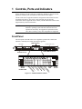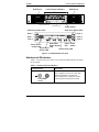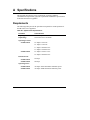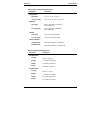
1
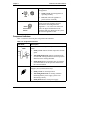
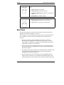
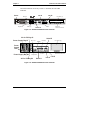
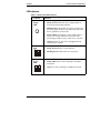
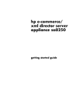
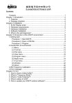
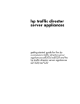
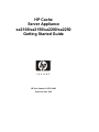
HP Cache
Server Appliance
sa2100/sa2150/sa2200/sa2250
Getting Started Guide
HP Part Number P4535-90003
Printed in July 2001
Notice
The information contained in this document is subject to change without notice.
Hewlett-Packard makes no warranty of any kind with regard to this material,
including, but not limited to, the implied warranties of merchantability and
fitness for a particular purpose. Hewlett-Packard shall not be liable for errors
contained herein or for incidental or consequential damages in connection with the
furnishing, performance, or use of this material.
Hewlett-Packard assumes no responsibility for the use or reliability of its software
on equipment that is not furnished by Hewlett-Packard.
This document contains proprietary information that is protected by copyright. All
rights are reserved. No part of this document may be photocopied, reproduced, or
translated to another language without the prior written consent of
Hewlett-Packard Company.
Microsoft, Windows, and Internet Explorer are registered trademarks of Microsoft
in the U.S. and other countries. MacOS is a registered trademark of Apple
Computer, Incorporated. Intel and Pentium are registered trademarks of Intel
Corporation. Netscape and Navigator are registered trademarks of Netscape
Communications Corporation in the U.S. and other countries. Adobe and Acrobat
are registered trademarks of Adobe Systems Incorporated in the U.S. and other
countries.
Hewlett-Packard Company
Network Server Division
Technical Communications/ MS 45S-LE
10955 Tantau Avenue
Cupertino, California 95014 USA
© Copyright 2001, Hewlett-Packard Company.
Audience Assumptions
This guide is for the person who installs, administers, and troubleshoots network
infrastructure products. Hewlett-Packard Company assumes you are qualified in
the servicing of computer equipment and trained in recognizing hazards in
products with hazardous energy levels.
ii
Contents
1 Controls, Ports and Indicators........................................................................1
Front Panel.........................................................................................................1
Switches and LED Indicators .........................................................................2
Component Indicators ....................................................................................3
Rear Panel .........................................................................................................4
LED Indicators................................................................................................6
Applying Power to the Appliance .......................................................................7
Powering-Up the Appliance ...........................................................................7
Powering-Down the Appliance.......................................................................7
Connecting AC Power to Multiple-Server Configurations ..............................8
2 Rack Mounting..................................................................................................9
3 Configuring the Cache Appliance ................................................................11
Overview ..........................................................................................................11
Information You Will Need ...............................................................................11
Configuring Initial Network Parameters for LAN A...........................................12
Supplemental Configuration.............................................................................13
Monitoring Traffic Server ..................................................................................14
4 Online Documentation CD-ROM ...................................................................15
5 Troubleshooting .............................................................................................17
A Specifications .................................................................................................19
Requirements ...................................................................................................19
Index ....................................................................................................................21
iii
1 Controls, Ports and Indicators
Before operating your HP Cache Server Appliance, familiarize yourself with the
appliance's controls, ports, and indicators as described in this chapter.
The HP Cache Server Appliance hardware configuration and software has been
optimized at the factory. The power, LAN, and serial ports are the only
connections that are supported. Please contact your HP authorized reseller or HP
Support directly for more information.
NOTE
This appliance carries a whole unit exchange warranty. The
hardware, operating system and cache software have been
optimized at the factory. No upgrades or replacement of the
CPU, drives, memory or any other component are supported.
Front Panel
The front panel of the HP Cache Server Appliance provides the controls and
indicators commonly used when operating the appliance.
LED Indicators
CD-ROM
Power LED & Switch
SCSI Drives (3)
Reset
Switch
DO NOT USE
Flexible Disk Drive
Te
m
SC
D
Fa
D
Power
is Dis
ns isk
SI
k
k
LED
pe
I
I
A
I
D
D
D
ra
ct
1
2
0
iv
tu
ity
re
Power
Switch
Figure 1-1. sa2100/sa2150 Front Panel
1
Chapter 1
Controls, Ports and Indicators
SCSI Drives
SCSI Drives
Control Panel Indicators
Flexible Disk Drive
CD-ROM Drive
Power Switch
SCSI Drive Status LEDs
SCSI Drive Status LEDs
Disk 0
Disk 3
Disk 1
Disk 4
Disk 2
Disk 5
Redundant
Power Power
Power Supply
LED Switch
DO NOT USE
LED
Temperature
SCSI Activity LED
& Fans LED
Reset Switch
Figure 1-2. sa2200/sa2250 Front Panel
Switches and LED Indicators
Table 1-1 describes the power switch, reset switch and LED indicators located on
the front panel.
Table 1-1. Power Switch and Indicators
Control/Indicator
Power On/Off Switch
Push-button
Switch
2
Description
This push-button switch turns the HP Cache
Server Appliance power On or Off. Shut
down the appliance as described in
“Powering-Down the Appliance” before
powering down with the power switch.
Chapter 1
Controls, Ports and Indicators
On/Off LED
This green LED provides the power state of
the appliance:
• Steady Green when the appliance is
operating normally
LED
• Off (unlit) when the appliance is
powered off or in standby
Reset Switch
RESET
Push-button
Switch
DO NOT USE THE RESET SWITCH.
Always power the appliance down as
described in “Powering-Down the
Appliance”. Use of the reset switch will
cause an ungraceful shutdown of the
appliance that may damage the file system
or cause the appliance to fail.
Component Indicators
Table 1-2 describes the front panel component LED indicators.
Table 1-2. Component Indicators
LED ICON
Description
Temperature/Fan
LED
This LED indicates the system temperature and fan speed
status:
• Steady Green indicates normal temperature and fan
speed.
• Alternating Red/Green indicates temperature has
exceeded the warning threshold or the fan speed has
fallen below the warning threshold.
• Steady Red indicates temperature has exceeded the
critical threshold or the fan speed has fallen below
the critical threshold.
RPS LED
This LED indicates the status of the Redundant Power
Supply system (sa2200/sa2250 only):
• Steady Green for normal operation.
• Alternating Red/Green for warning condition
indicating that the power supply system is not
functioning correctly.
• Steady Red indicates a bad power supply.
3
Chapter 1
Controls, Ports and Indicators
SCSI Drive
Status LEDs
These LEDs indicate the state of the respective SCSI disk
drive:
• Off for SCSI drive not present.
• Steady Green for SCSI drive present.
• Alternating Red/Green (fast blink) for a SCSI drive
identify.
• Steady Red for SCSI drive failure.
SCSI Activity LED
This LED indicates SCSI Hard Disk activity:
• Flickering Green when there is SCSI activity.
• Off when there is no power or SCSI activity.
Rear Panel
The connectors and ports are located on the rear panel of the HP Cache Server
Appliance are illustrated in Figures 1-3 and 1-4.
The following is a list of the connectors and ports that are used by the HP Cache
Server Appliance. The other connectors and ports on the rear panel are not
required.
• The power connector accepts a standard power cable to connect the
HP Cache Server Appliance with a UPS or site power source. A second
power supply for redundancy is installed in the sa2200/sa2250. Each power
supply has its own power cord connection.
• The serial port labeled “Serial/Management Port” is a standard serial port
that can be used to attach a laptop or PC for console-based configuration as
described in Chapter 3.
• The dedicated serial port (Serial B) on the sa2200/sa2250 is a standard serial
port that can also be used to attach a laptop or PC for console-based
configuration as described in Chapter 3.
• The two LAN ports (LAN A and LAN B) are for the embedded network
adapters based on Intel's 82559 10/100 BaseT Fast Ethernet adapter. Each
LAN port has a RJ-45 LAN connector and two LEDs to indicate LAN speed
4
Chapter 1
Controls, Ports and Indicators
and valid connection or activity. Table 1-3 describes the LAN LED
indicators.
Power
Lan A
Mouse
Keyboard
USB (2)
Lan B
PCI Slot (1)
External
SCSI Connector
Video
Serial A
Figure 1-3. sa2100/sa2150 Rear Panel and Ports
AC for PS Bay #1
Power Supply Bay #1
Serial B
Mouse
USB(2)
PCI Slots (3)
Parallel
Power
Supply
LED
Power Supply Bay #2
Keyboard
AC for PS Bay #2
External SCSI Port
Video
Serial A
Lan B
Lan A
Figure 1-4. sa2200/sa2250 Rear Panel and Ports
5
Chapter 1
Controls, Ports and Indicators
LED Indicators
Table 1-3. Rear Panel LED Indicators
Indicator
Power
Supply
LED
Definition
Each power supply module has a status LED:
• Steady Green indicates the power supply module is
powered up and operating normally.
• Flashing Green indicates that AC current is present and
the power supply module is in standby mode (HP Cache
Server Appliance is powered off).
• Steady Amber may indicate a power module failure, a
system over-current condition, a blown fuse in the
power supply module or cage, or that no AC is present.
• Off indicates the AC line cord is unplugged from all
installed power modules.
Link
LED
This LED is the activity/link indicator:
• Steady Green indicates a valid LAN link.
• Flashing Green indicates there is LAN activity.
LAN
Speed
LED
This LED is the LAN speed indicator:
• Steady Amber shows LAN is operating at 100 Mbps
LAN speed
• Off shows LAN is operating at 10 Mbps LAN speed
6
Chapter 1
Controls, Ports and Indicators
Applying Power to the Appliance
Powering-Up the Appliance
1. Ensure that the HP Cache Server Appliance's power cord and network cables
are connected prior to powering on the appliance.
2. Press the Power push-button on the front control panel.
When you press the power button on the control panel, the appliance powers
up and loads the operating system. The system runs a set of power on
self-tests (POST) during this process.
Powering-Down the Appliance
• Schedule the power down for a time when it will affect the least users.
• Before powering down, insure that the Traffic Server settings have been
backed up by using the Snapshots button in Traffic Manager as described in
the HP Cache Server Appliance Administrator Guide.
WARNING
The HP Cache Server Appliance MUST be shut down through
a telnet or VT100 serial session before powering down with
the power switch, reset switch or by removing the power
cable.
1. Shutdown the appliance by establishing a telnet or serial port connection and
selecting shutdown.
2. Once the disk activity LED stops blinking (about 1 minute) it is safe to turn
the appliance off with the power switch.
7
Chapter 1
Controls, Ports and Indicators
Connecting AC Power to Multiple-Server Configurations
The HP Cache Server Appliance temporarily draws a large "inrush current" when
first connected to an AC power source. This also occurs when the appliance is in a
standby mode (power is turned off, but the power cord is plugged into AC power).
The inrush current is much greater than the appliance's normal operating current.
The AC power source can handle the inrush current under normal circumstances.
However, the following factors must be considered when installing several HP
Cache Server Appliances on one circuit:
• If there is a power failure and power is then restored, all the servers
immediately begin to draw inrush current at the same time.
• If the circuit breakers on the incoming power line have insufficient
capability, the breaker may trip and thus prevent the servers from powering
up.
When preparing your site for installation, allow for the additional inrush current.
Refer to Table A-1, "System Power Specifications," in Appendix A.
8
2 Rack Mounting
The HP Cache Server Appliance can be rack mounted in a variety of 2 and 4 post
racking configurations. The appliances are shipped with the rails needed for 4 post
racking configurations already installed.
NOTE
Read the complete racking instructions in the HP Cache Server
Appliance sa2100/sa2150 and sa2200/sa2250 Rack Mounting
Supplements on your documentation CD-ROM before
attempting to rack mount these appliances.
General racking information is included on the label on the top of the appliance.
More detailed racking information, including the use of additional rack mounting
hardware for alternative rack mounting (such as two-post racking), can be found in
the HP Cache Server Appliance sa2100/sa2150 and sa2200/sa2250 Rack
Mounting Supplements.
9
3 Configuring the Cache Appliance
This chapter describes the initial configuration process required to install the cache
appliance on the network.
Overview
The following is an overview of the configuration steps:
1. Configure initial network parameters for LAN A of the appliance
a. through DHCP/bootp
- OR b. via a VT100 serial console session
2. Accept the settings thereby starting the Traffic Server application.
3. Additional network parameters can be configured through a telnet or VT100
serial session.
4. Use Traffic Manager to customize the cache proxy settings. Access Traffic
Manager by directing your browser to: http://<appliance_IP_address>:8081
where 8081 is the default traffic manager port.
Information You Will Need
• A fully qualified hostname; i.e., webproxy.ca.hp.com
• IP address
• Subnet mask
• Gateway IP address
• Primary DNS IP address
• You will be prompted to establish an optional telnet access user name and
password
11
Chapter 3
Configuring the Cache Appliance
Configuring Initial Network Parameters for LAN A
If the appliance has received an IP address through bootp or DHCP and you know
the IP address, you may use telnet to access the initial configuration session. (The
MAC address is printed on a label on the right side of the appliance as viewed
from the front or on the RJ45 connector.)
1. Telnet to the appliance IP address and use hpsaconfig for the user name and
hpsa for the password.
2. Once you establish the telnet session, follow the prompts on the screen to
complete the initial configuration.
CAUTION
The hpsaconfig user will be deleted when the initial
configuration is successfully completed. If a telnet access user
name and password is not supplied during the initial network
configuration, you will not be able to access the appliance
with telnet. Access to the appliance will always be available
through a serial VT100 session in case you do not supply a
telnet access user name and password at initial configuration
and later wish to configure one.
If the appliance did not receive an IP address through bootp or DHCP:
1. Access the initial configuration session with a VT100 terminal session over a
serial cable.
2. Connect your client PC serial port to the serial port on the appliance with the
serial cable provided with the appliance.
3. Configure the terminal software (such as HyperTerminal on a Microsoft
Windows-based client) to connect using the appropriate com port. Set the
port speed to 9600, 8 data bits, no parity, 1 stop bit, and no flow control.
4. Press Enter on the client PC to establish the initial configuration session.
5. When prompted, login to the appliance using the user name hpsaconfig and
the password hpsa.
6. Follow the prompts on the screen to complete the initial configuration.
Once in the initial network configuration, you will be prompted to create a telnet
access account by supplying a user name and password. You must create this user
name and password in order to have telnet access to the appliance after this initial
configuration session. Several Traffic Server management tasks require telnet
access.
12
Chapter 3
Configuring the Cache Appliance
Upon successful completion of the initial configuration, the appliance will start
and configure the Traffic Server software to run with the network settings just
entered.
NOTE
After the initial configurations are saved, the network
parameters will be saved as a static configuration on the
appliance. This is true even if the appliance received the initial
IP configuration via bootp or DHCP. DHCP and bootp will be
disabled on the appliance after the initial network configuration
is complete.
Supplemental Configuration
Once you have completed the initial configuration, the HP Cache Server
Appliance will be operating with default settings as a proxy cache server. Clients
may configure their browsers to use the appliance as their proxy server at this
point with the default proxy port of 8080; however, you may wish to make further
configuration and customization changes.
Configuring the Traffic Server caching application can best be accomplished as
described in the HP Cache Server Appliance Administrator Guide by directing a
browser to: http://<appliance_IP_address>:8081 where 8081 is the default port for
administration using Traffic Manager.
To access any of the system-level functionality listed below, telnet to the appliance
using the telnet access user name and password that was entered during initial
configuration (see “Configuring Initial Network Parameters for LAN A” for
details).
The following activities may be performed through the Configuration menu:
• Change network configuration for the network adapters
• Change the hostname of the appliance
• Set date, time, and time zone
• Change the console port user name and password
• Shutdown and restart
• Restore factory defaults
• Obtain shell access to run commands required to manage Traffic Server
13
Chapter 3
Configuring the Cache Appliance
Monitoring Traffic Server
Once Traffic Server is up and running, you can monitor and modify its operation
from the Traffic Manager Dashboard. The Dashboard is shown in Figure 3-1.
Access Traffic Manager by directing your browser to:
http://<appliance_IP_address>:8081 where 8081 is the default traffic manager
port.
The HP Cache Server Appliance Administrator Guide describes how to use Traffic
Manager.
Figure 3-1. Traffic Server Dashboard
14
4 Online Documentation CD-ROM
The HP Server Appliance Documentation CD-ROM contains the entire set of
documentation for your HP Cache Server Appliance. The CD-ROM provides a
web-based interface that allows you to quickly locate information.
To use this CD-ROM you must have a browser (either Microsoft Internet Explorer
4.x (or greater), or Netscape Navigator version 4.x (or greater) and Adobe Acrobat
Reader version 3.x or greater.
The CD-ROM may be accessed in one of the following ways:
• the CD-ROM should start automatically when inserted into a PC
- OR • point your browser to index.htm under the start directory of the
CD-ROM.
15
5 Troubleshooting
DO NOT remove the cover from the HP Cache Server Appliance. There are no
upgradeable or customer-replaceable parts inside the appliance.
NOTE
This appliance carries a whole unit exchange warranty and no
upgrades or replacement of CPU, drives, memory, or any other
components are supported.
For troubleshooting information go to:
http://www.hp.com/serverappliances/support
17
A Specifications
This appendix provides the power requirements, operating conditions
(environmental requirements), physical requirements and hardware specifications
of the HP Cache Server Appliance.
Requirements
The following tables provide the specifications required for normal operation of
the HP Cache Server Appliance.
Table A-1. System Power Specifications
Parameter
Characteristics
Input Type
Universal input
Input Range
100 to 240 VAC at 50/60 Hz
Operating Current
sa2100/sa2150
2.6 Amps at 100 VAC
2.1 Amps at 120 VAC
1.3 Amps at 200-208 VAC
1.2 Amps at 230-240 VAC
sa2200/sa2250
4.3 Amps at 100-127 VAC
2.2 Amps at 200-240 VAC
Inrush Current
sa2100/sa2150
65 Amps
sa2200/sa2250
60 Amps
Operating Power
sa2100/sa2150
AC Input: 266 W maximum continuous power
sa2200/sa2250
AC Input: 260W maximum continuous power
19
Appendix A
Specifications
Table A-2. Environmental Requirements
Parameter
Conditions
Temperature
Operating
5° to 35° C (41° to 95° F)
Non-operating
-40° to +65° C (-40° to +149° F)
Humidity
Operating
20% to 80% relative humidity,
non-condensing
Non-operating
5% to 95% relative humidity,
non-condensing
Altitude
Operating
-30 to 3,045 m (10,000 ft)
Non-operating
-30 to 12,180 m (40,000 ft)
Thermal Output
sa2100/sa2150
maximum operating: 867 BTU/hr
sa2200/sa2250
maximum operating: 1,365 BTU/hr
Table A-3. Weight and Dimensions
Parameter
Conditions
sa2100/sa2150
Weight
32 lbs. (14.5 kg)
Height
1.75 inches (44.5 mm)
Width
16.8 inches (428 mm)
Depth
23 inches (585 mm)
sa2200/sa2250
20
Weight
38 lbs. (17.3 kg)
Height
3.36 inches (85.4 mm)
Width
16.8 inches (428 mm)
Depth
23.3 inches (591 mm)
Index
C
component indicators, 3
configuring Traffic Server, 11
E
environmental requirements, 20
F
front panel, 1
H
HP Cache Server Appliance
controls, 2
front panel, 2
indicators, 2
inrush current, 8
power switch, 2
powering down, 2, 3, 7
powering up, 7
rear panel, 4
I
indicators
LEDs, 3
on/off, 3
inrush current
allowing for, 8
specifications, 19
L
LAN
LEDs, 6
RJ45 port, 6
LAN speed LED, 6
LED indicators
front panel, 1
rear panel, 6
link LED, 6
M
monitoring Traffic Server, 14
multiple-server configurations
connecting AC power, 8
O
on/off LED, 3
online documentation CD-ROM, 15
automatic start, 15
P
ports
LAN port, 5
serial, 4
power supply LED, 6
power switch, 2
powering-down procedure, 2, 3, 7
powering-on procedure, 7
R
rack mounting, 9
rear panel, 4
reset switch, 3
RPS LED, 3
S
SCSI activity LED, 4
SCSI drive status LEDs, 4
site preparation
environmental considerations, 20
specifications, 19
system power specifications, 19
T
temperature/fan LED, 3
troubleshooting, 17
W
weight and dimensions, 20
21