1
user guide
hp StorageWorks
fabric OS procedures version
3.1.x/4.1.x
Product Version: V3.1.x/V4.1.x
Third Edition (June 2003)
Part Number: AA–RS23C–TE
This guide describes the procedures for configuring switches, working with the management
server, working with diagnostics, and displaying switch status information.
© Copyright 1999-2003 Hewlett-Packard Development Company, L.P.
Hewlett-Packard Company makes no warranty of any kind with regard to this material, including, but not limited to,
the implied warranties of merchantability and fitness for a particular purpose. Hewlett-Packard shall not be liable for
errors contained herein or for incidental or consequential damages in connection with the furnishing, performance,
or use of this material.
This document contains proprietary information, which is protected by copyright. No part of this document may be
photocopied, reproduced, or translated into another language without the prior written consent of Hewlett-Packard.
The information contained in this document is subject to change without notice.
BROCADE, the Brocade B weave logo, Brocade: the Intelligent Platform for Networking Storage, SilkWorm, and
SilkWorm Express, are trademarks or registered trademarks of Brocade Communications Systems, Inc. or its
subsidiaries in the United States and/or in other countries.
Microsoft®, MS Windows®, Windows®, and Windows NT® are U.S. registered trademarks of Microsoft
Corporation.
UNIX® is a registered trademark of The Open Group.
Hewlett-Packard Company shall not be liable for technical or editorial errors or omissions contained herein. The
information is provided “as is” without warranty of any kind and is subject to change without notice. The warranties
for Hewlett-Packard Company products are set forth in the express limited warranty statements for such products.
Nothing herein should be construed as constituting an additional warranty.
Printed in the U.S.A.
Fabric OS Procedures Version 3.1.x/4.1.x User Guide
Third Edition (June 2003)
Part Number: AA–RS23C–TE
contents
1
Contents
Initial Configuration . . . . . . . . . . . . . . . . . . . . . . . . . . . . . . . . . . . . . . . . . . . . . . . .13
Connecting and Configuring the Switch. . . . . . . . . . . . . . . . . . . . . . . . . . . . . . . . . . . . . . . . . 14
Physically Connecting to the Switch . . . . . . . . . . . . . . . . . . . . . . . . . . . . . . . . . . . . . . . . 14
Power on the Switch. . . . . . . . . . . . . . . . . . . . . . . . . . . . . . . . . . . . . . . . . . . . . . . . . . . . . 14
Configuring the IP Addresses . . . . . . . . . . . . . . . . . . . . . . . . . . . . . . . . . . . . . . . . . . . . . 14
Configuring the IP Address for the SAN Switch 2/16 . . . . . . . . . . . . . . . . . . . . . . . 14
Configuring the Control Processor IP Addresses for the SAN Switch 2/32 . . . . . . . . . . 15
Configuring IP Addresses for the Core Switch 2/64 . . . . . . . . . . . . . . . . . . . . . . . . . . . . 16
Configuring the Control Processors: . . . . . . . . . . . . . . . . . . . . . . . . . . . . . . . . . . . . . 16
Configuring a Logical Switch IP Address for the Core Switch 2/64 . . . . . . . . . . . . 18
Initial Setup Example. . . . . . . . . . . . . . . . . . . . . . . . . . . . . . . . . . . . . . . . . . . . . . . . . . . . 19
Switch Login. . . . . . . . . . . . . . . . . . . . . . . . . . . . . . . . . . . . . . . . . . . . . . . . . . . . . . . . . . . . . . 21
Logging Into the Switch. . . . . . . . . . . . . . . . . . . . . . . . . . . . . . . . . . . . . . . . . . . . . . . . . . 21
Changing the Admin Password in v3.1 Firmware . . . . . . . . . . . . . . . . . . . . . . . . . . . . . . 22
Changing the Admin Password in v4.1 Firmware . . . . . . . . . . . . . . . . . . . . . . . . . . . . . . 23
Customize the Switch Name. . . . . . . . . . . . . . . . . . . . . . . . . . . . . . . . . . . . . . . . . . . . . . . . . . 24
Customizing a Switch Name . . . . . . . . . . . . . . . . . . . . . . . . . . . . . . . . . . . . . . . . . . . . . . 24
Manage Licensed Features . . . . . . . . . . . . . . . . . . . . . . . . . . . . . . . . . . . . . . . . . . . . . . . . . . . 25
Obtaining Optional Software License Keys from HP . . . . . . . . . . . . . . . . . . . . . . . . . . . 25
Activating a License. . . . . . . . . . . . . . . . . . . . . . . . . . . . . . . . . . . . . . . . . . . . . . . . . . . . . 26
Verifying License Activation. . . . . . . . . . . . . . . . . . . . . . . . . . . . . . . . . . . . . . . . . . . . . . 26
Configure Fabric Parameters . . . . . . . . . . . . . . . . . . . . . . . . . . . . . . . . . . . . . . . . . . . . . . . . . 28
Understanding the Core PID Requirements. . . . . . . . . . . . . . . . . . . . . . . . . . . . . . . . . . . 28
Mixed Fabric Requirements. . . . . . . . . . . . . . . . . . . . . . . . . . . . . . . . . . . . . . . . . . . . . . . 28
(Optional) Enabling Core PID Addressing . . . . . . . . . . . . . . . . . . . . . . . . . . . . . . . . . . . 29
Considering Additional Fabric Configurations . . . . . . . . . . . . . . . . . . . . . . . . . . . . . . . . 29
Configure Software Features . . . . . . . . . . . . . . . . . . . . . . . . . . . . . . . . . . . . . . . . . . . . . . . . . 30
Verify Switch Function. . . . . . . . . . . . . . . . . . . . . . . . . . . . . . . . . . . . . . . . . . . . . . . . . . . . . . 31
Connect ISLs to Switch . . . . . . . . . . . . . . . . . . . . . . . . . . . . . . . . . . . . . . . . . . . . . . . . . . . . . 33
Verifying the Fabric Connectivity . . . . . . . . . . . . . . . . . . . . . . . . . . . . . . . . . . . . . . . . . . 33
Fabric OS Procedures Version 3.1.x/4.1.x User Guide
3
Contents
Connect Devices to the Switch . . . . . . . . . . . . . . . . . . . . . . . . . . . . . . . . . . . . . . . . . . . . . . . .
Verifying Device Connectivity . . . . . . . . . . . . . . . . . . . . . . . . . . . . . . . . . . . . . . . . . . . .
Backing up Switch Configuration Information . . . . . . . . . . . . . . . . . . . . . . . . . . . . . . . . . . .
Making a Hard Copy of Switch Information . . . . . . . . . . . . . . . . . . . . . . . . . . . . . . . . . .
Saving the Switch Configuration File to a Host. . . . . . . . . . . . . . . . . . . . . . . . . . . . . . . .
35
35
37
37
37
2
Basic Switch Management . . . . . . . . . . . . . . . . . . . . . . . . . . . . . . . . . . . . . . . . . . . .39
Switch Enable/Disable Procedures . . . . . . . . . . . . . . . . . . . . . . . . . . . . . . . . . . . . . . . . . . . . . 40
Disabling a Switch . . . . . . . . . . . . . . . . . . . . . . . . . . . . . . . . . . . . . . . . . . . . . . . . . . . . . . 40
Enabling a Switch . . . . . . . . . . . . . . . . . . . . . . . . . . . . . . . . . . . . . . . . . . . . . . . . . . . . . . 40
Disabling a Port . . . . . . . . . . . . . . . . . . . . . . . . . . . . . . . . . . . . . . . . . . . . . . . . . . . . . . . . 41
Enabling a Port. . . . . . . . . . . . . . . . . . . . . . . . . . . . . . . . . . . . . . . . . . . . . . . . . . . . . . . . . 43
Domain IDs. . . . . . . . . . . . . . . . . . . . . . . . . . . . . . . . . . . . . . . . . . . . . . . . . . . . . . . . . . . . . . . 47
Display a Current List of Domain IDs . . . . . . . . . . . . . . . . . . . . . . . . . . . . . . . . . . . . . . . 47
Setting a Domain ID. . . . . . . . . . . . . . . . . . . . . . . . . . . . . . . . . . . . . . . . . . . . . . . . . . . . . 48
Firmware Versions . . . . . . . . . . . . . . . . . . . . . . . . . . . . . . . . . . . . . . . . . . . . . . . . . . . . . . . . . 49
Displaying the Firmware Version and Information . . . . . . . . . . . . . . . . . . . . . . . . . . . . . 49
Switch Date and Time . . . . . . . . . . . . . . . . . . . . . . . . . . . . . . . . . . . . . . . . . . . . . . . . . . . . . . 51
Setting the Switch Date and Time . . . . . . . . . . . . . . . . . . . . . . . . . . . . . . . . . . . . . . . . . . 51
Synchronize Local Time with an External Source. . . . . . . . . . . . . . . . . . . . . . . . . . . . . . 52
Fabric Configuration Settings. . . . . . . . . . . . . . . . . . . . . . . . . . . . . . . . . . . . . . . . . . . . . . . . . 53
Displaying the Fabric Configuration Settings . . . . . . . . . . . . . . . . . . . . . . . . . . . . . . . . . 53
Backing Up the System Configuration Settings. . . . . . . . . . . . . . . . . . . . . . . . . . . . . . . . 54
Restoring the System Configuration Settings . . . . . . . . . . . . . . . . . . . . . . . . . . . . . . . . . 55
Switch Names . . . . . . . . . . . . . . . . . . . . . . . . . . . . . . . . . . . . . . . . . . . . . . . . . . . . . . . . . . . . . 57
Changing a Switch Name. . . . . . . . . . . . . . . . . . . . . . . . . . . . . . . . . . . . . . . . . . . . . . . . . 57
Switch Status Policies. . . . . . . . . . . . . . . . . . . . . . . . . . . . . . . . . . . . . . . . . . . . . . . . . . . . . . . 58
Viewing the Policy Threshold Values . . . . . . . . . . . . . . . . . . . . . . . . . . . . . . . . . . . . . . . 58
Configuring the Policy Threshold Values . . . . . . . . . . . . . . . . . . . . . . . . . . . . . . . . . . . . 59
Tracking Switch Changes . . . . . . . . . . . . . . . . . . . . . . . . . . . . . . . . . . . . . . . . . . . . . . . . . . . . 63
Enabling the Track Changes Feature . . . . . . . . . . . . . . . . . . . . . . . . . . . . . . . . . . . . . . . . 63
Displaying Whether Track Changes are Enabled . . . . . . . . . . . . . . . . . . . . . . . . . . . . . . 64
Routing . . . . . . . . . . . . . . . . . . . . . . . . . . . . . . . . . . . . . . . . . . . . . . . . . . . . . . . . . . . . . . . . . . 65
Forcing In-order Delivery of Frames . . . . . . . . . . . . . . . . . . . . . . . . . . . . . . . . . . . . . . . . 65
Restoring In-order Delivery of Frames . . . . . . . . . . . . . . . . . . . . . . . . . . . . . . . . . . . . . . 66
Using Dynamic Load-Sharing . . . . . . . . . . . . . . . . . . . . . . . . . . . . . . . . . . . . . . . . . . . . . 66
Viewing Routing Path Information . . . . . . . . . . . . . . . . . . . . . . . . . . . . . . . . . . . . . . . . . 67
Help Commands . . . . . . . . . . . . . . . . . . . . . . . . . . . . . . . . . . . . . . . . . . . . . . . . . . . . . . . . . . . 71
Displaying Help Information for a Command . . . . . . . . . . . . . . . . . . . . . . . . . . . . . . . . . 71
4
Fabric OS Procedures Version 3.1.x/4.1.x User Guide
Contents
Additional Help Topics . . . . . . . . . . . . . . . . . . . . . . . . . . . . . . . . . . . . . . . . . . . . . . . . . . 72
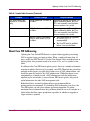
Hexadecimal Port Diagrams . . . . . . . . . . . . . . . . . . . . . . . . . . . . . . . . . . . . . . . . . . . . . . . . . . 73
Reading Hexadecimal Port Diagrams . . . . . . . . . . . . . . . . . . . . . . . . . . . . . . . . . . . . . . . 73
3
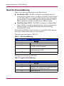
Firmware Download . . . . . . . . . . . . . . . . . . . . . . . . . . . . . . . . . . . . . . . . . . . . . . . .75
About Firmware Downloads. . . . . . . . . . . . . . . . . . . . . . . . . . . . . . . . . . . . . . . . . . . . . . . . . . 76
Understanding the Dual-CP Firmware Upgrade Process. . . . . . . . . . . . . . . . . . . . . . . . . 76
Non-Disruptive Firmware Activation . . . . . . . . . . . . . . . . . . . . . . . . . . . . . . . . . . . . . . . 77
The Firmware Upgrade Process . . . . . . . . . . . . . . . . . . . . . . . . . . . . . . . . . . . . . . . . . . . . . . . 78
Upgrading the Firmware on the SAN Switch 2/32 . . . . . . . . . . . . . . . . . . . . . . . . . . . . . 78
Upgrading the Firmware on the Core Switch 2/64 . . . . . . . . . . . . . . . . . . . . . . . . . . . . . 80
Customizing the Firmware Download Process . . . . . . . . . . . . . . . . . . . . . . . . . . . . . . . . 83
Downloading Firmware to a Single CP on a Core Switch 2/64 . . . . . . . . . . . . . . . . 84
Upgrading the Firmware Using Web Tools . . . . . . . . . . . . . . . . . . . . . . . . . . . . . . . . . . . 87
Upgrading the Firmware Using the CLI . . . . . . . . . . . . . . . . . . . . . . . . . . . . . . . . . . . . . 88
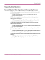
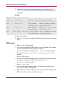
Frequently Asked Questions. . . . . . . . . . . . . . . . . . . . . . . . . . . . . . . . . . . . . . . . . . . . . . . . . . 89
Password Migration When Upgrading and Downgrading Firmware . . . . . . . . . . . . . . . 89
4
Basic Security in FOS. . . . . . . . . . . . . . . . . . . . . . . . . . . . . . . . . . . . . . . . . . . . . . . .91
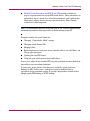
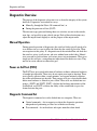
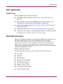
Overview. . . . . . . . . . . . . . . . . . . . . . . . . . . . . . . . . . . . . . . . . . . . . . . . . . . . . . . . . . . . . . . . . 92
New Features . . . . . . . . . . . . . . . . . . . . . . . . . . . . . . . . . . . . . . . . . . . . . . . . . . . . . . . . . . . . . 93
Ensuring a Secure Operating System. . . . . . . . . . . . . . . . . . . . . . . . . . . . . . . . . . . . . . . . 93
Secure Shell (SSH). . . . . . . . . . . . . . . . . . . . . . . . . . . . . . . . . . . . . . . . . . . . . . . . . . . . . . 93
Disabling the Telnet Interface . . . . . . . . . . . . . . . . . . . . . . . . . . . . . . . . . . . . . . . . . . . . . 95
Listeners . . . . . . . . . . . . . . . . . . . . . . . . . . . . . . . . . . . . . . . . . . . . . . . . . . . . . . . . . . . . . . 95
Removal of Unused Listeners . . . . . . . . . . . . . . . . . . . . . . . . . . . . . . . . . . . . . . . . . . 95
Passwords . . . . . . . . . . . . . . . . . . . . . . . . . . . . . . . . . . . . . . . . . . . . . . . . . . . . . . . . . . . . . . . . 97
About Passwords . . . . . . . . . . . . . . . . . . . . . . . . . . . . . . . . . . . . . . . . . . . . . . . . . . . . . . . 97
Default Fabric and Switch Accessibility . . . . . . . . . . . . . . . . . . . . . . . . . . . . . . . . . . . . . 98
Hosts: . . . . . . . . . . . . . . . . . . . . . . . . . . . . . . . . . . . . . . . . . . . . . . . . . . . . . . . . . . . . . 98
Devices: . . . . . . . . . . . . . . . . . . . . . . . . . . . . . . . . . . . . . . . . . . . . . . . . . . . . . . . . . . . 98
Switch Access:. . . . . . . . . . . . . . . . . . . . . . . . . . . . . . . . . . . . . . . . . . . . . . . . . . . . . . 98
Zoning:. . . . . . . . . . . . . . . . . . . . . . . . . . . . . . . . . . . . . . . . . . . . . . . . . . . . . . . . . . . . 99
Managing Passwords . . . . . . . . . . . . . . . . . . . . . . . . . . . . . . . . . . . . . . . . . . . . . . . . . . . . 99
Modifying a Password . . . . . . . . . . . . . . . . . . . . . . . . . . . . . . . . . . . . . . . . . . . . . . . . 99
Setting Recovery Passwords . . . . . . . . . . . . . . . . . . . . . . . . . . . . . . . . . . . . . . . . . . . . . 100
About Boot Prom Passwords. . . . . . . . . . . . . . . . . . . . . . . . . . . . . . . . . . . . . . . . . . 100
Setting Both the Boot PROM and the Recovery Passwords (SAN Switch 2/32) . . 100
Setting Both the Boot PROM and Recovery Passwords (Core Switch 2/64) . . . . . 101
Fabric OS Procedures Version 3.1.x/4.1.x User Guide
5
Contents
Setting the Boot PROM Password Only (SAN Switch 2/32) . . . . . . . . . . . . . . . . .
Setting the Boot PROM Password Only (Core Switch 2/64) . . . . . . . . . . . . . . . . .
About Forgotten Passwords. . . . . . . . . . . . . . . . . . . . . . . . . . . . . . . . . . . . . . . . . . .
Recovering a User, Admin, or Factory Password . . . . . . . . . . . . . . . . . . . . . . . . . .
Recovering a Forgotten Root or Boot PROM Password. . . . . . . . . . . . . . . . . . . . .
Frequently Asked Questions . . . . . . . . . . . . . . . . . . . . . . . . . . . . . . . . . . . . . . . . . . . . .
102
104
106
106
106
106
5
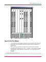
Working With the Core Switch 2/64 . . . . . . . . . . . . . . . . . . . . . . . . . . . . . . . . . . .109
Ports on the Core Switch 2/64 . . . . . . . . . . . . . . . . . . . . . . . . . . . . . . . . . . . . . . . . . . . . . . . 110
About the Slot/Port Method . . . . . . . . . . . . . . . . . . . . . . . . . . . . . . . . . . . . . . . . . . . . . . 111
About the Port Area Number Method . . . . . . . . . . . . . . . . . . . . . . . . . . . . . . . . . . . . . . 112
Determining the Area Number (ID) of a Port . . . . . . . . . . . . . . . . . . . . . . . . . . . . . . . . 112
Basic Blade Management . . . . . . . . . . . . . . . . . . . . . . . . . . . . . . . . . . . . . . . . . . . . . . . . . . . 115
Disabling a Blade . . . . . . . . . . . . . . . . . . . . . . . . . . . . . . . . . . . . . . . . . . . . . . . . . . . . . . 115
Enabling a Blade . . . . . . . . . . . . . . . . . . . . . . . . . . . . . . . . . . . . . . . . . . . . . . . . . . . . . . 116
Powering On a Blade . . . . . . . . . . . . . . . . . . . . . . . . . . . . . . . . . . . . . . . . . . . . . . . . . . . 116
Powering Off a Blade. . . . . . . . . . . . . . . . . . . . . . . . . . . . . . . . . . . . . . . . . . . . . . . . . . . 116
Core Switch 2/64 Chassis . . . . . . . . . . . . . . . . . . . . . . . . . . . . . . . . . . . . . . . . . . . . . . . . . . . 118
Displaying the Status of All Slots in the Chassis. . . . . . . . . . . . . . . . . . . . . . . . . . . . . . 118
Displaying Information on Switch FRUs. . . . . . . . . . . . . . . . . . . . . . . . . . . . . . . . . . . . 119
Blade Beacon Mode . . . . . . . . . . . . . . . . . . . . . . . . . . . . . . . . . . . . . . . . . . . . . . . . . . . . . . . 123
Setting the Blade Beacon Mode. . . . . . . . . . . . . . . . . . . . . . . . . . . . . . . . . . . . . . . . . . . 123
6
The SAN Management Application . . . . . . . . . . . . . . . . . . . . . . . . . . . . . . . . . . . .125
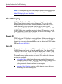
The Management Server. . . . . . . . . . . . . . . . . . . . . . . . . . . . . . . . . . . . . . . . . . . . . . . . . . . . 126
Benefits . . . . . . . . . . . . . . . . . . . . . . . . . . . . . . . . . . . . . . . . . . . . . . . . . . . . . . . . . . . . . 126
Configuring Access to the Management Server . . . . . . . . . . . . . . . . . . . . . . . . . . . . . . . . . . 128
Displaying the Access Control List . . . . . . . . . . . . . . . . . . . . . . . . . . . . . . . . . . . . . . . . 128
Adding a WWN to the Access Control List. . . . . . . . . . . . . . . . . . . . . . . . . . . . . . . . . . 128
Deleting a WWN from the Access Control List . . . . . . . . . . . . . . . . . . . . . . . . . . . . . . 130
Displaying the Management Server Database . . . . . . . . . . . . . . . . . . . . . . . . . . . . . . . . . . . 133
Clearing the Management Server Database . . . . . . . . . . . . . . . . . . . . . . . . . . . . . . . . . . . . . 134
Activating the Platform Management Service . . . . . . . . . . . . . . . . . . . . . . . . . . . . . . . . . . . 135
Deactivating the Platform Management Service . . . . . . . . . . . . . . . . . . . . . . . . . . . . . . . . . 136
Controlling the Topology Discovery . . . . . . . . . . . . . . . . . . . . . . . . . . . . . . . . . . . . . . . . . . 137
Display the Status of MS Topology Discovery Service. . . . . . . . . . . . . . . . . . . . . . . . . 137
Enable the MS Topology Discovery Feature . . . . . . . . . . . . . . . . . . . . . . . . . . . . . . . . . 137
Disable the MS Topology Discovery Feature . . . . . . . . . . . . . . . . . . . . . . . . . . . . . . . . 138
6
Fabric OS Procedures Version 3.1.x/4.1.x User Guide
Contents
7
Updating Switches to the Core PID Addressing . . . . . . . . . . . . . . . . . . . . . . . . . . . .139
Overview. . . . . . . . . . . . . . . . . . . . . . . . . . . . . . . . . . . . . . . . . . . . . . . . . . . . . . . . . . . . . . . . 140
Determining If You Need to Enable the Core PID . . . . . . . . . . . . . . . . . . . . . . . . . . . . 142
Example Scenarios . . . . . . . . . . . . . . . . . . . . . . . . . . . . . . . . . . . . . . . . . . . . . . . . . 142
About Core PID Addressing . . . . . . . . . . . . . . . . . . . . . . . . . . . . . . . . . . . . . . . . . . . . . 143
About Fibre Channel Addressing. . . . . . . . . . . . . . . . . . . . . . . . . . . . . . . . . . . . . . . . . . 144
Recommendations . . . . . . . . . . . . . . . . . . . . . . . . . . . . . . . . . . . . . . . . . . . . . . . . . . . . . 145
New Fabrics. . . . . . . . . . . . . . . . . . . . . . . . . . . . . . . . . . . . . . . . . . . . . . . . . . . . . . . 145
Existing Fabrics . . . . . . . . . . . . . . . . . . . . . . . . . . . . . . . . . . . . . . . . . . . . . . . . . . . . 145
About PID Mapping. . . . . . . . . . . . . . . . . . . . . . . . . . . . . . . . . . . . . . . . . . . . . . . . . . . . 146
Dynamic PID . . . . . . . . . . . . . . . . . . . . . . . . . . . . . . . . . . . . . . . . . . . . . . . . . . . . . . 146
Static PID. . . . . . . . . . . . . . . . . . . . . . . . . . . . . . . . . . . . . . . . . . . . . . . . . . . . . . . . . 146
Evaluate the Fabric . . . . . . . . . . . . . . . . . . . . . . . . . . . . . . . . . . . . . . . . . . . . . . . . . . . . . . . . 148
Gathering Information . . . . . . . . . . . . . . . . . . . . . . . . . . . . . . . . . . . . . . . . . . . . . . . . . . 148
Collect Device, Software, Hardware, and Config Data. . . . . . . . . . . . . . . . . . . . . . 148
Make List of Manually Configurable PID Drivers . . . . . . . . . . . . . . . . . . . . . . . . . 149
Analyzing Data. . . . . . . . . . . . . . . . . . . . . . . . . . . . . . . . . . . . . . . . . . . . . . . . . . . . . . . . 149
Performing Empirical Testing . . . . . . . . . . . . . . . . . . . . . . . . . . . . . . . . . . . . . . . . . 150
Planning the Update Procedure . . . . . . . . . . . . . . . . . . . . . . . . . . . . . . . . . . . . . . . . . . . . . . 151
Outline for Online Update Procedure . . . . . . . . . . . . . . . . . . . . . . . . . . . . . . . . . . . . . . 151
Outline for Offline Update Procedure . . . . . . . . . . . . . . . . . . . . . . . . . . . . . . . . . . . . . . 152
Hybrid Update . . . . . . . . . . . . . . . . . . . . . . . . . . . . . . . . . . . . . . . . . . . . . . . . . . . . . . . . 153
Procedures for Updating the Core PID Format . . . . . . . . . . . . . . . . . . . . . . . . . . . . . . . . . . 154
Basic Update Procedures . . . . . . . . . . . . . . . . . . . . . . . . . . . . . . . . . . . . . . . . . . . . . . . . 154
Detailed Update Procedures for HP/UX and AIX . . . . . . . . . . . . . . . . . . . . . . . . . . . . . 155
HP/UX . . . . . . . . . . . . . . . . . . . . . . . . . . . . . . . . . . . . . . . . . . . . . . . . . . . . . . . . . . . 155
AIX Procedure. . . . . . . . . . . . . . . . . . . . . . . . . . . . . . . . . . . . . . . . . . . . . . . . . . . . . 158
Frequently Asked Questions. . . . . . . . . . . . . . . . . . . . . . . . . . . . . . . . . . . . . . . . . . . . . . . . . 160
8
Diagnostics and Status . . . . . . . . . . . . . . . . . . . . . . . . . . . . . . . . . . . . . . . . . . . . .161
Diagnostics Overview. . . . . . . . . . . . . . . . . . . . . . . . . . . . . . . . . . . . . . . . . . . . . . . . . . . . . . 162
Manual Operation. . . . . . . . . . . . . . . . . . . . . . . . . . . . . . . . . . . . . . . . . . . . . . . . . . . . . . 162
Power on Self Test (POST) . . . . . . . . . . . . . . . . . . . . . . . . . . . . . . . . . . . . . . . . . . . . . . 162
Diagnostic Command Set. . . . . . . . . . . . . . . . . . . . . . . . . . . . . . . . . . . . . . . . . . . . . . . . 162
Interactive Diagnostic Commands . . . . . . . . . . . . . . . . . . . . . . . . . . . . . . . . . . . . . . . . . 164
Persistent Error Log . . . . . . . . . . . . . . . . . . . . . . . . . . . . . . . . . . . . . . . . . . . . . . . . . . . . . . . 165
Displaying the Error Log Without Page Breaks . . . . . . . . . . . . . . . . . . . . . . . . . . . . . . 166
Displaying the Error Log With Page Breaks . . . . . . . . . . . . . . . . . . . . . . . . . . . . . . . . . 167
Clearing the Switch Error Log . . . . . . . . . . . . . . . . . . . . . . . . . . . . . . . . . . . . . . . . . . . . 167
Fabric OS Procedures Version 3.1.x/4.1.x User Guide
7
Contents
Setting the Error Save Level of a Switch . . . . . . . . . . . . . . . . . . . . . . . . . . . . . . . . . . . .
Displaying the Current Error Save Level Setting of a Switch . . . . . . . . . . . . . . . . . . . .
Resizing the Persistent Error Log . . . . . . . . . . . . . . . . . . . . . . . . . . . . . . . . . . . . . . . . .
Showing the Current Persistent (Non-Volatile) Error Log Configuration of a Switch .
Syslog Daemon. . . . . . . . . . . . . . . . . . . . . . . . . . . . . . . . . . . . . . . . . . . . . . . . . . . . . . . . . . .
syslogd Overview. . . . . . . . . . . . . . . . . . . . . . . . . . . . . . . . . . . . . . . . . . . . . . . . . . . . . .
syslog Error Message Format. . . . . . . . . . . . . . . . . . . . . . . . . . . . . . . . . . . . . . . . . . . . .
Message Classification. . . . . . . . . . . . . . . . . . . . . . . . . . . . . . . . . . . . . . . . . . . . . . . . . .
Syslogd CLI Commands . . . . . . . . . . . . . . . . . . . . . . . . . . . . . . . . . . . . . . . . . . . . . . . .
Configuring syslogd . . . . . . . . . . . . . . . . . . . . . . . . . . . . . . . . . . . . . . . . . . . . . . . . . . . .
Configuring syslogd on the Remote Host . . . . . . . . . . . . . . . . . . . . . . . . . . . . . . . .
Enabling syslogd on the Core Switch 2/64 or SAN Switch 2/32 . . . . . . . . . . . . . .
Disabling syslogd on the Core Switch 2/64 or SAN Switch 2/32 . . . . . . . . . . . . . .
Switch Diagnostics . . . . . . . . . . . . . . . . . . . . . . . . . . . . . . . . . . . . . . . . . . . . . . . . . . . . . . . .
Displaying the Switch Status . . . . . . . . . . . . . . . . . . . . . . . . . . . . . . . . . . . . . . . . . . . . .
Displaying Information About a Switch . . . . . . . . . . . . . . . . . . . . . . . . . . . . . . . . . . . .
Displaying the Uptime Of the Switch . . . . . . . . . . . . . . . . . . . . . . . . . . . . . . . . . . . . . .
Port Diagnostics . . . . . . . . . . . . . . . . . . . . . . . . . . . . . . . . . . . . . . . . . . . . . . . . . . . . . . . . . .
Displaying Software Statistics for a Port . . . . . . . . . . . . . . . . . . . . . . . . . . . . . . . . . . . .
Displaying Hardware Statistics for a Port . . . . . . . . . . . . . . . . . . . . . . . . . . . . . . . . . . .
Displaying a Summary of Port Errors . . . . . . . . . . . . . . . . . . . . . . . . . . . . . . . . . . . . . .
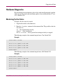
Hardware Diagnostics. . . . . . . . . . . . . . . . . . . . . . . . . . . . . . . . . . . . . . . . . . . . . . . . . . . . . .
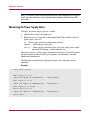
Monitoring the Fan Status . . . . . . . . . . . . . . . . . . . . . . . . . . . . . . . . . . . . . . . . . . . . . . .
Monitoring the Power Supply Status . . . . . . . . . . . . . . . . . . . . . . . . . . . . . . . . . . . . . . .
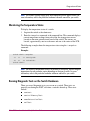
Monitoring the Temperature Status . . . . . . . . . . . . . . . . . . . . . . . . . . . . . . . . . . . . . . . .
Running Diagnostic Tests on the Switch Hardware . . . . . . . . . . . . . . . . . . . . . . . . . . .
Linux Root Capabilities . . . . . . . . . . . . . . . . . . . . . . . . . . . . . . . . . . . . . . . . . . . . . . . . . . . .
168
168
169
170
171
171
171
172
173
173
173
174
175
176
176
176
180
181
181
183
185
187
187
188
189
189
191
9
Troubleshooting . . . . . . . . . . . . . . . . . . . . . . . . . . . . . . . . . . . . . . . . . . . . . . . . . .193
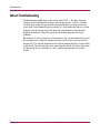
About Troubleshooting. . . . . . . . . . . . . . . . . . . . . . . . . . . . . . . . . . . . . . . . . . . . . . . . . . . . . 194
Fibre Channel Process . . . . . . . . . . . . . . . . . . . . . . . . . . . . . . . . . . . . . . . . . . . . . . . . . . 195
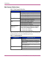
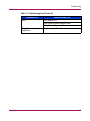
Most Common Problem Areas. . . . . . . . . . . . . . . . . . . . . . . . . . . . . . . . . . . . . . . . . . . . 196
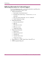
Gathering Information for Technical Support . . . . . . . . . . . . . . . . . . . . . . . . . . . . . . . . . . . 198
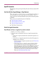
Specific Scenarios. . . . . . . . . . . . . . . . . . . . . . . . . . . . . . . . . . . . . . . . . . . . . . . . . . . . . . . . . 199
Host Can Not See Target (Storage or Tape Devices) . . . . . . . . . . . . . . . . . . . . . . . . . . 199
Check the Logical Connection . . . . . . . . . . . . . . . . . . . . . . . . . . . . . . . . . . . . . . . . . . . . 199
Check Whether the Device is Logically Connected to the Switch . . . . . . . . . . . . . 199
Check the Simple Name Server (SNS) . . . . . . . . . . . . . . . . . . . . . . . . . . . . . . . . . . . . . 200
Check for the Device in the SNS. . . . . . . . . . . . . . . . . . . . . . . . . . . . . . . . . . . . . . . 200
8
Fabric OS Procedures Version 3.1.x/4.1.x User Guide
Contents
Check for Zoning Discrepancies . . . . . . . . . . . . . . . . . . . . . . . . . . . . . . . . . . . . . . . . . .
Fabric Segmentation. . . . . . . . . . . . . . . . . . . . . . . . . . . . . . . . . . . . . . . . . . . . . . . . . . . .
Possible Causes . . . . . . . . . . . . . . . . . . . . . . . . . . . . . . . . . . . . . . . . . . . . . . . . . . . .
About Fabric Parameters . . . . . . . . . . . . . . . . . . . . . . . . . . . . . . . . . . . . . . . . . . . . . . . .
Domain ID Conflicts . . . . . . . . . . . . . . . . . . . . . . . . . . . . . . . . . . . . . . . . . . . . . . . . . . .
Restore a Segmented Fabric. . . . . . . . . . . . . . . . . . . . . . . . . . . . . . . . . . . . . . . . . . . . . .
Reconcile Fabric Parameters Individually. . . . . . . . . . . . . . . . . . . . . . . . . . . . . . . .
Restore Fabric Parameters Through ConfigUpload . . . . . . . . . . . . . . . . . . . . . . . .
Reconcile a Domain ID Conflict . . . . . . . . . . . . . . . . . . . . . . . . . . . . . . . . . . . . . . .
Zoning Setup Issues . . . . . . . . . . . . . . . . . . . . . . . . . . . . . . . . . . . . . . . . . . . . . . . . . . . .
Zoning Related Commands . . . . . . . . . . . . . . . . . . . . . . . . . . . . . . . . . . . . . . . . . . .
Fabric Merge Conflicts Related to Zoning. . . . . . . . . . . . . . . . . . . . . . . . . . . . . . . . . . .
Prevention . . . . . . . . . . . . . . . . . . . . . . . . . . . . . . . . . . . . . . . . . . . . . . . . . . . . . . . .
Basic Zone Merge Correction Procedure. . . . . . . . . . . . . . . . . . . . . . . . . . . . . . . . . . . .
Detailed Zone Merge Correction Procedure . . . . . . . . . . . . . . . . . . . . . . . . . . . . . . . . .
Verify Fabric Merge Problem . . . . . . . . . . . . . . . . . . . . . . . . . . . . . . . . . . . . . . . . .
Edit Zone Config Members . . . . . . . . . . . . . . . . . . . . . . . . . . . . . . . . . . . . . . . . . . .
Reorder the Zone Member List . . . . . . . . . . . . . . . . . . . . . . . . . . . . . . . . . . . . . . . .
MQ-WRITE Error . . . . . . . . . . . . . . . . . . . . . . . . . . . . . . . . . . . . . . . . . . . . . . . . . . . . .
I2C bus Errors . . . . . . . . . . . . . . . . . . . . . . . . . . . . . . . . . . . . . . . . . . . . . . . . . . . . . . . .
Possible Causes . . . . . . . . . . . . . . . . . . . . . . . . . . . . . . . . . . . . . . . . . . . . . . . . . . . .
Troubleshooting the Hardware . . . . . . . . . . . . . . . . . . . . . . . . . . . . . . . . . . . . . . . .
Check Fan Components . . . . . . . . . . . . . . . . . . . . . . . . . . . . . . . . . . . . . . . . . .
Check the Switch Temperature . . . . . . . . . . . . . . . . . . . . . . . . . . . . . . . . . . . . .
Check the Power Supply . . . . . . . . . . . . . . . . . . . . . . . . . . . . . . . . . . . . . . . . . .
Check the Temperature, Fan, and Power Supply . . . . . . . . . . . . . . . . . . . . . . .
Device Login Issues . . . . . . . . . . . . . . . . . . . . . . . . . . . . . . . . . . . . . . . . . . . . . . . . . . . . . . .
Watchdog (Best Practices) . . . . . . . . . . . . . . . . . . . . . . . . . . . . . . . . . . . . . . . . . . . . . . . . . .
Actions . . . . . . . . . . . . . . . . . . . . . . . . . . . . . . . . . . . . . . . . . . . . . . . . . . . . . . . . . . . . . .
Kernel Software Watchdog Related Errors . . . . . . . . . . . . . . . . . . . . . . . . . . . . . . . . . .
kSWD-APP_NOT_REFRESH_ERR . . . . . . . . . . . . . . . . . . . . . . . . . . . . . . . . . . .
kSWD-kSWD_GENERIC_ERR_CRITICAL. . . . . . . . . . . . . . . . . . . . . . . . . . . . .
Identifying Media-Related Issues . . . . . . . . . . . . . . . . . . . . . . . . . . . . . . . . . . . . . . . . . . . . .
Component Tests Overview. . . . . . . . . . . . . . . . . . . . . . . . . . . . . . . . . . . . . . . . . . . . . .
Check Switch Components . . . . . . . . . . . . . . . . . . . . . . . . . . . . . . . . . . . . . . . . . . . . . .
Cursory Debugging of Media Components. . . . . . . . . . . . . . . . . . . . . . . . . . . . . . .
Test Cascaded Switch ISL Links. . . . . . . . . . . . . . . . . . . . . . . . . . . . . . . . . . . . . . .
Test a Port’s External Transmit and Receive Path . . . . . . . . . . . . . . . . . . . . . . . . .
Fabric OS Procedures Version 3.1.x/4.1.x User Guide
202
203
203
203
204
204
204
205
205
206
206
207
207
207
208
208
208
209
209
210
210
210
210
210
210
211
212
216
216
217
217
217
218
218
219
219
220
221
9
Contents
Test a Switches Internal Components . . . . . . . . . . . . . . . . . . . . . . . . . . . . . . . . . . .
Test Components To and From the HBA . . . . . . . . . . . . . . . . . . . . . . . . . . . . . . . .
Check All Switch Components Between Main Board, SFP, and Fiber Cable . . . .
Check Port’s External Transmit and Receive Path . . . . . . . . . . . . . . . . . . . . . . . . .
Check all Switch Components of the Port Transmit and Receive Path. . . . . . . . . .
Additional Component Tests . . . . . . . . . . . . . . . . . . . . . . . . . . . . . . . . . . . . . . . . . .
Link Failure . . . . . . . . . . . . . . . . . . . . . . . . . . . . . . . . . . . . . . . . . . . . . . . . . . . . . . . . . . . . .
Possible Causes for Link Failure . . . . . . . . . . . . . . . . . . . . . . . . . . . . . . . . . . . . . . . . . .
Switch State . . . . . . . . . . . . . . . . . . . . . . . . . . . . . . . . . . . . . . . . . . . . . . . . . . . . . . .
Port’s Physical State . . . . . . . . . . . . . . . . . . . . . . . . . . . . . . . . . . . . . . . . . . . . . . . .
Speed Negotiation Failure . . . . . . . . . . . . . . . . . . . . . . . . . . . . . . . . . . . . . . . . . . . .
Link Initialization Failure (Loop) . . . . . . . . . . . . . . . . . . . . . . . . . . . . . . . . . . . . . .
Point-to-Point Initialization Failure. . . . . . . . . . . . . . . . . . . . . . . . . . . . . . . . . . . . .
Port Has Come Up in a Wrong Mode . . . . . . . . . . . . . . . . . . . . . . . . . . . . . . . . . . .
Marginal Links . . . . . . . . . . . . . . . . . . . . . . . . . . . . . . . . . . . . . . . . . . . . . . . . . . . . . . . . . . .
Confirming the Problem. . . . . . . . . . . . . . . . . . . . . . . . . . . . . . . . . . . . . . . . . . . . . . . . .
Isolating the Areas . . . . . . . . . . . . . . . . . . . . . . . . . . . . . . . . . . . . . . . . . . . . . . . . . . . . .
Ruling Out Cabling Issues . . . . . . . . . . . . . . . . . . . . . . . . . . . . . . . . . . . . . . . . . . . . . . .
Nx_Port (Host or Storage) Issues. . . . . . . . . . . . . . . . . . . . . . . . . . . . . . . . . . . . . . . . . .
222
222
223
225
227
228
229
229
229
230
230
231
232
232
234
234
235
236
236
Glossary. . . . . . . . . . . . . . . . . . . . . . . . . . . . . . . . . . . . . . . . . . . . . . . . . . . . . . . .237
Index . . . . . . . . . . . . . . . . . . . . . . . . . . . . . . . . . . . . . . . . . . . . . . . . . . . . . . . . . .269
Figures
1 Graphic Illustration of Core Switch 2/64 . . . . . . . . . . . . . . . . . . . . . . . . . . . . . . . . . . . . 111
2 Switch Update Requirements. . . . . . . . . . . . . . . . . . . . . . . . . . . . . . . . . . . . . . . . . . . . . 141
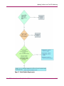
3 Fibre Channel Process Flow Chart. . . . . . . . . . . . . . . . . . . . . . . . . . . . . . . . . . . . . . . . . 195
Tables
1 Areas to be Configured for the Core Switch 2/64 . . . . . . . . . . . . . . . . . . . . . . . . . . . . . . 16
2 Description of configupload Options . . . . . . . . . . . . . . . . . . . . . . . . . . . . . . . . . . . . . . . . 38
3 Switch Series and Applicable Firmware . . . . . . . . . . . . . . . . . . . . . . . . . . . . . . . . . . . . . 49
4 Hexidecimal to binary conversions . . . . . . . . . . . . . . . . . . . . . . . . . . . . . . . . . . . . . . . . . 73
5 Removed Listeners for the Core Switch 2/64 and SAN Switch 2/32 . . . . . . . . . . . . . . . 95
6 SAN Switch 2/32 Password Accounts . . . . . . . . . . . . . . . . . . . . . . . . . . . . . . . . . . . . . . . 97
7 Core Switch 2/64 Password Accounts . . . . . . . . . . . . . . . . . . . . . . . . . . . . . . . . . . . . . . . 98
8 Sample Fabric Scenarios . . . . . . . . . . . . . . . . . . . . . . . . . . . . . . . . . . . . . . . . . . . . . . . . 142
10
Fabric OS Procedures Version 3.1.x/4.1.x User Guide
Contents
9
10
11
12
13
14
15
16
17
18
19
20
21
16-Port Count Addressing . . . . . . . . . . . . . . . . . . . . . . . . . . . . . . . . . . . . . . . . . . . . . . .
Larger Port Count Addressing . . . . . . . . . . . . . . . . . . . . . . . . . . . . . . . . . . . . . . . . . . . .
Error Summary Description . . . . . . . . . . . . . . . . . . . . . . . . . . . . . . . . . . . . . . . . . . . . . .
Most Common Problem Areas. . . . . . . . . . . . . . . . . . . . . . . . . . . . . . . . . . . . . . . . . . . .
Troubleshooting Tools . . . . . . . . . . . . . . . . . . . . . . . . . . . . . . . . . . . . . . . . . . . . . . . . . .
Zoning Related Commands . . . . . . . . . . . . . . . . . . . . . . . . . . . . . . . . . . . . . . . . . . . . . .
Zone Specific Commands . . . . . . . . . . . . . . . . . . . . . . . . . . . . . . . . . . . . . . . . . . . . . . .
Types of Zone Discrepancies . . . . . . . . . . . . . . . . . . . . . . . . . . . . . . . . . . . . . . . . . . . . .
Component Test Descriptions . . . . . . . . . . . . . . . . . . . . . . . . . . . . . . . . . . . . . . . . . . . .
Switch Component Tests . . . . . . . . . . . . . . . . . . . . . . . . . . . . . . . . . . . . . . . . . . . . . . . .
SwitchState and Actions to Take . . . . . . . . . . . . . . . . . . . . . . . . . . . . . . . . . . . . . . . . . .
Port States and Suggested Actions. . . . . . . . . . . . . . . . . . . . . . . . . . . . . . . . . . . . . . . . .
SwitchShow Output and Suggested Action . . . . . . . . . . . . . . . . . . . . . . . . . . . . . . . . . .
Fabric OS Procedures Version 3.1.x/4.1.x User Guide
144
144
185
196
196
206
206
207
218
228
229
230
232
11
Contents
12
Fabric OS Procedures Version 3.1.x/4.1.x User Guide
Initial Configuration
1
This chapter provides information on initial configuration tasks for a switch.
■
Connecting and Configuring the Switch, page 14
■
Switch Login, page 21
■
Changing the Admin Password in v4.1 Firmware, page 23
■
Manage Licensed Features, page 25
■
Configure Fabric Parameters, page 28
■
Configure Software Features, page 30
■
Verify Switch Function, page 31
■
Connect ISLs to Switch, page 33
■
Connect Devices to the Switch, page 35
■
Backing up Switch Configuration Information, page 37
Fabric OS Procedures Version 3.1.x/4.1.x User Guide
13
Initial Configuration
Connecting and Configuring the Switch
Perform the following tasks when initially connecting the switch:
Physically Connecting to the Switch
Beginning communication with the new switch requires a serial connection. Refer
to the specific hardware manual for your switch for instructions on physically
connecting to the switch.
Power on the Switch
Power on the switch. When the switch is powered on, it automatically runs the
Power On Self Test (POST) to guarantee switch stability. Errors that occur during
POST are written to the system error log. Verify that the POST completes
successfully. Refer to the appropriate HP Fibre Channel Switch Hardware
Reference Manualsfor more information about powering the switch and
understanding the POST.
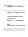
Configuring the IP Addresses
Configuring the IP Address for the SAN Switch 2/16
The switch is shipped with a default IP address of 10.77.77.77. To change the
default IP Address and configure the Fibre Channel IP address of the switch:
1. Log into the switch as the admin user.
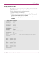
2. At the command line, enter the ipaddrset command. An interactive
session is opened and you are prompted for configuration values. Press the
Enter key without entering a value to skip over a prompt and leave the
parameter value as is.
3. At the Ethernet IP Address prompt, enter the new IP address for the ethernet
port on the switch. Press the Enter key to continue.
4. At the Ethernet Subnetmask prompt, enter the address of the subnetmask, if
applicable. Press the Enter key to continue.
5. At the Fibre Channel IP address prompt, enter the Fibre Channel IP address
for the switch. Press the Enter key to continue.
6. At the Fibre Channel Subnetmask prompt, enter the address of the
subnetmask, if applicable. Press the Enter key to continue.
14
Fabric OS Procedures Version 3.1.x/4.1.x User Guide
Initial Configuration
7. At the Gateway Address prompt, enter the IP address of the gateway system if
applicable. Press the Enter key to continue.
The configuration is then committed to the switch firmware.
8. You are then prompted whether to make the IP address changes active now or
at the next reboot. Enter y at the prompt to have the IP address changes take
effect immediately.
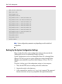
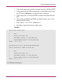
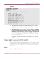
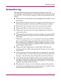
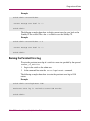
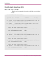
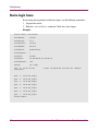
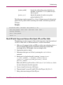
The following example shows how to configure the IP address for a SAN Switch
2/16 using the ipaddrset command.
Example:
switch:admin> ipaddrset
Ethernet IP Address [10.32.53.136]:
Ethernet Subnetmask [255.255.240.0]:
Fibre Channel IP Address [none]:
Fibre Channel Subnetmask [none]:
Gateway Address [10.32.48.1]:
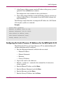
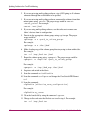
Configuring the Control Processor IP Addresses for the SAN Switch 2/32
The SAN Switch 2/32 has one Control Processor (CP) for which the Ethernet IP
and host information must be configured.
1. Have the following information available for the new switch:
— Ethernet IP Address
— Ethernet Subnetmask
— Hostname
— Gateway IP Address
2. Log in to the switch as the admin user.
3. Enter the ipaddrset command at the command line. An interactive
session is opened.
4. Enter the Ethernet IP address and click Enter.
5. Enter the Ethernet Subnetmask and click Enter.
6. Enter the Hostname and click Enter.
7. Enter the Gateway IP Address and click Enter.
Fabric OS Procedures Version 3.1.x/4.1.x User Guide
15
Initial Configuration
8. Enter the ippaddrset command to verify the data you entered, and exit.
9. Repeat the steps to configure all SAN Switch 2/32 switches.
Example:
switch:admin> ipaddrset
Ethernet IP Address [10.77.77.77]: 10.64.119.7
Ethernet Subnetmask [10.77.77.76]: 255.255.240.0
Fibre Channel IP Address [0.0.0.0]:
Fibre Channel Subnetmask [0.0.0.0]:
Gateway IP Address [10.64.112.1]:
IP address being changed...
Committing configuration...Done.
switch:admin>
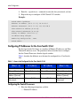
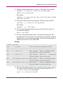
Configuring IP Addresses for the Core Switch 2/64
For the Core Switch 2/64, there are a number of Ethernet IP addresses and Fibre
Channel IP addresses to set. The procedures below describes how to configure
first the Control Processors, then the logical switches.
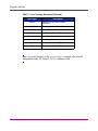
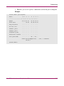
Table 1 describes the different areas that must be configured for a Core Switch
2/64.
Table 1: Areas to be Configured for the Core Switch 2/64
Logical Switch 0
(Slots 1 - 4)
CP 0 (Slot 5)
CP 1 (Slot 6)
Logical Switch 1
(Slots 7 - 10)
Ethernet IP Address
Ethernet IP Address
Ethernet IP Address
Ethernet IP Address
Ethernet Subnetmask
Ethernet Subnetmask
Ethernet Subnetmask
Ethernet Subnetmask
Fibre Channel IP
Address (Optional)
Hostname
Hostname
Fibre Channel IP
Address (Optional)
Fibre Channel
Subnetmask
Gateway IP Address
Gateway IP Address
Fibre Channel
Subnetmask
Configuring the Control Processors:
1. Have the following information available:
— Ethernet IP Address
16
Fabric OS Procedures Version 3.1.x/4.1.x User Guide
Initial Configuration
— Ethernet Subnetmask
— Hostname
— Gateway IP Address
2. Log in to the switch as the admin user.
3. Enter the ipaddrset command at the command line. An interactive
session is opened.
4. Choose the CP that you want to configure. Enter the value that corresponds to
that logical region:
— Enter 2 to configure CP 0 (slot 5).
— Enter 3 to configure CP 1 (slot 6).
5. Enter the Ethernet IP Address when prompted. Click Enter.
6. Enter the Ethernet Subnetmask when prompted. Click Enter.
7. Enter the Hostname when prompted. Click Enter.
8. Enter the Gateway IP Address when prompted. Click Enter.
9. Enter the ippaddrshow command to verify the data you entered, and exit.
10. Enter the hafailover command to make the second CP active.
11. Repeat steps 1 through 9 to configure the second CP.
12. See “Configuring a Logical Switch IP Address for the Core Switch 2/64” to
configure the logical switch IP addresses.
Fabric OS Procedures Version 3.1.x/4.1.x User Guide
17
Initial Configuration
Example:
switch:admin> ipaddrset
Switch number [0 for switch0, 1 for switch1, 2 for CP0, 3 for CP1]: 2
Ethernet IP Address [192.168.186.61]:
Ethernet Subnetmask [255.255.255.0]:
Hostname [192.168.68.193]:
Gateway IP [255.255.255.0]:
Committing configuration...Done.
switch:admin>
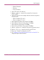
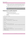
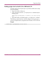
Configuring a Logical Switch IP Address for the Core Switch 2/64
1. Have the following information available:
— Ethernet IP Address
— Ethernet Subnetmask
— Fibre Channel IP Address (Optional)
— Fibre Channel Subnetmask
2. Log in to the switch as the admin user.
3. Enter the ipaddrset command at the command line. An interactive
session is opened.
4. Choose the logical switch that you want to configure. Enter the value that
corresponds to that logical region:
— Enter 0 to configure logical switch 0 (slot 1 though 4)
— Enter 1 to configure logical switch 1 (slot 7 though 10)
5. Enter the Ethernet IP address when prompted. Click Enter
6. Enter the Ethernet Subnetmask when prompted. Click Enter
7. (Optional) Enter the Fibre Channel IP address. Click Enter
8. Enter the Fibre Channel Subnetmask. Click Enter
9. Enter the ippaddrshow command to verify the data you entered, and exit.
10. Repeat step 1 through step 9 to configure the second logical switch.
18
Fabric OS Procedures Version 3.1.x/4.1.x User Guide
Initial Configuration
Example:
switch:admin> ipaddrset
Switch number [0 for switch0, 1 for switch1, 2 for CP0, 3 for CP1]: 0
Ethernet IP Address [192.168.186.61]:
Ethernet Subnetmask [255.255.255.0]:
Fibre Channel IP Address [192.168.68.193]:
Fibre Channel Subnetmask [255.255.255.0]:
Committing configuration...Done.
switch:admin>
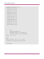
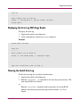
Initial Setup Example
The following example shows an initial setup of a Core Switch 2/64.
Example: Core Switch 2/64
login: admin
password: xxxxxxx
switch:admin> ipaddrset
Switch number [0 for switch0, 1 for switch1, 2 for CP0, 3 for CP1]: 2
Ethernet IP Address [10.32.162.104]:
Ethernet Subnetmask [255.255.255.0]:
Fibre Channel IP Address [192.168.68.193]:
Fibre Channel Subnetmask [255.255.255.0]:
Committing configuration...Done.
switch:admin> ipaddrset
Switch number [0 for switch0, 1 for switch1, 2 for CP0, 3 for CP1]: 3
Ethernet IP Address [10.32.162.105]:
Ethernet Subnetmask [255.255.255.0]:
Hostname [192.168.68.193]:
Gateway IP [255.255.255.0]:
Committing configuration...Done.
Fabric OS Procedures Version 3.1.x/4.1.x User Guide
19
Initial Configuration
switch:admin> ipaddrset
Switch number [0 for switch0, 1 for switch1, 2 for CP0, 3 for CP1]: 0
Ethernet IP Address [10.32.162.106]:
Ethernet Subnetmask [255.255.255.0]:
Hostname [192.168.68.193]:
Gateway IP [255.255.255.0]:
Committing configuration...Done.
switch:admin> ipaddrset
Switch number [0 for switch0, 1 for switch1, 2 for CP0, 3 for CP1]: 1
Ethernet IP Address [10.32.162.107]:
Ethernet Subnetmask [255.255.255.0]:
Hostname [192.168.68.193]:
Gateway IP [255.255.255.0]:
Committing configuration...Done.
20
Fabric OS Procedures Version 3.1.x/4.1.x User Guide
Initial Configuration
Switch Login
The following sections describe logging into a switch and changing the admin
password.
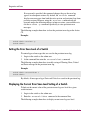
Logging Into the Switch
To perform the initial login into a switch:
1. Verify that the switch is connected to your IP network through the RJ-45
ethernet port to enable connection through telnet. Refer to the hardware
manual of your specific switch for more information about connecting the
switch to your IP network.
2. Open a telnet connection to the switch.
The login prompt is displayed if the telnet connection successfully found the
switch in the network.
3. Enter the user ID (usually user or admin) at the login prompt.
Example:
login: admin
4. Enter the default admin password. The default password is password.
You will be prompted to change the password.
Example:
password: xxxxxxx
5. Enter new password or press Ctrl+C.
6. Verify that the login was successful. A prompt is displayed showing the
switch name and user ID to which you are logged.
Example:
login: admin
password: xxxxxxx
switch:admin>
Fabric OS Procedures Version 3.1.x/4.1.x User Guide
21
Initial Configuration
Changing the Admin Password in v3.1 Firmware
For security reasons, the first time you log into the Fabric OS you are requested to
change the system password. The following procedure applies specifically to v3.1.
To change the admin password:
1. Log into the switch as the admin user.
2. Enter the passwd admin command. In v3.0.1 you must specify the user
level when modifying the password.
Note: Quotation marks must be used for complete initialization of this command.
Example:
switch:admin> passwd "admin"
3. An interactive session is started where you can change the admin user name
and the password. If you want to change the admin user name, at the New
username prompt, enter a new name for the admin user. Click Return without
changing the value to leave it as is. You can change the password of the admin
user without changing the user name.
4. At the Old password prompt, enter the old password.
5. At the New password prompt, enter the new password. The new password
must be at least 8 characters in length.
6. At the Re-enter new password prompt, enter the new password
exactly as entered in the previous prompt. Press the Enter key to save the new
password to the firmware.
Example:
switch:admin> passwd "admin"
New username [admin]:
Old password: xxxxxxxx
New password: xxxxxxxx
Re-enter new password: xxxxxxxx
Saving passwd...done.
22
Fabric OS Procedures Version 3.1.x/4.1.x User Guide
Initial Configuration
Changing the Admin Password in v4.1 Firmware
The following procedures is specific to v4.1 firmware.
For security reasons, the first time you log in to the Fabric OS you are requested to
change the admin system passwords. There are four user levels: root, factory,
admin, and user. Most of the administration of an HP SAN or Core switch should
be done from the admin user level.
Note: You cannot reuse the default passwords.
To change the admin password:
1. Log in to the switch as the admin user.
2. Enter the passwd command. You are then prompted for information to
change the password.
3. At the Enter new password prompt, enter the new password.
4. At the Re-type new password prompt, enter the new password exactly
as entered at the previous prompt.
5. Press the enter key to commit the configuration to the firmware.
A message displays the successful storage of the new password.
Example:
switch:admin> passwd
Changing password for admin
Enter new password:
Re-type new password:
Password changed.
Saving password to stable storage.
Password saved to stable storage successfully.
switch:admin>
Fabric OS Procedures Version 3.1.x/4.1.x User Guide
23
Initial Configuration
Customize the Switch Name
You can customize the switch names for the logical switches. If you chose to
change the default switch name, use a switch name that is unique and meaningful.
Note: Changing the switch name causes a domain address format RSCN to be issued.
Switch Names
■
Can be up to 15 characters in length
■
Must begin with an alpha character
■
Can consist of any combination of alphanumeric and underscore characters
Default Names
The default names for the Core Switch 2/64 are “sw0” for the switch containing
the port cards in slots 1-4 and “sw1” for the switch containing port cards in slots 7
through 10.
Customizing a Switch Name
To customize the switch name, perform the following procedure.
1. Verify that there is a serial connection to the CP.
2. Log into the switch as admin.
3. (For Core Switch 2/64 switches only ) Choose the logical switch that you want
to change. Enter the value that corresponds to that logical region:
— Enter 0 to configure logical switch 0 (slot 1 though 4)
— Enter 1 to configure logical switch 1 (slot 7 though 10)
4. Enter the switchname command.
5. Enter the new name in quotes, as shown in the following example:
switchName "sw10"
For more information about this command, refer to the HP StorageWorks
Fabric OS Version 3.1.x/4.1.x Reference Guide
6. Record the new switch name for future reference.
7. (Optional) Log out of the session and repeat steps 1 through 6 for additional
switches.
24
Fabric OS Procedures Version 3.1.x/4.1.x User Guide
Initial Configuration
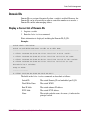
Manage Licensed Features
Licensed features such as Extended Fabric, QuickLoop, and Fabric Watch are
already loaded onto the switch firmware, but must be enabled with a license key.
Once you have purchased these features, you are provided with a key to unlock the
features in the firmware.
You can use several access methods to manage the switch (once the IP addresses
are set), including:
■
Telnet
■
Web Tools
■
Fabric Manager
■
A third party application using the API
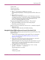
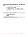
Obtaining Optional Software License Keys from HP
If you have purchased optional software, or need to reinstall software features due
to a motherboard replacement in your switch, you will need to retrieve the
software license keys from the HP Authorization Center.
Obtain software license keys as follows:
■
If you have your HP Registration Number, (located on your software
entitlement certificate) go to http://webkey.external.hp.com/welcome.asp.
■
If your HP Registration Number is unavailable, contact the Authorization
Center directly:
— Canada and United States, (Monday through Friday 6:00 am to 6:00 pm
MST), (801) 431-1451 or (800) 861-2979.
— Asia, (Monday through Friday 9:00 am to 5:00 pm), +81-03-3227-5289
or +81-3-3227-5289.
— Europe, Middle East, Africa and Netherlands (Monday through Friday
9:00 am to 6:00 pm), +31-555-384-210.
Fabric OS Procedures Version 3.1.x/4.1.x User Guide
25
Initial Configuration
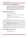
Activating a License
1. Log into the Command Line Interface as the Admin user.
2. To activate a license, you must have a valid license key. Use the license key
provided in the licensed Paper Pack.
Activate the license using the licenseadd command, as follows:
Example:
switch:admin> licenseadd “key”
Note: The license key is case-sensitive and must be entered exactly as given, enclosed
in double quotes.
3. Verify that the license was added by entering the licenseshow command
at the command line prompt.
A list displays all of the licenses currently installed on the switch.
Example:
switch:admin> licenseshow
1A1AaAaaaAAAA1a:
Web license
Zoning license
SES license
Security license
Fabric Watch license
If the licensed feature is listed, the feature is installed and immediately available.
If the license is not listed, repeat step 2 of this procedure.
Verifying License Activation
To verify that the required licenses are activated on the switch, perform the
following steps:
1. Log into the Command Line Interface as the Admin user.
2. Enter the licenseshow command at the command line prompt.
A list displays all of the licenses currently activated on the switch.
26
Fabric OS Procedures Version 3.1.x/4.1.x User Guide
Initial Configuration
Example:
switch:admin> licenseshow
SbQdRdzedzTcReS1:
Web license
bR9SeSydbckSATf1:
Trunking license
yQbze9eyzRc0f4:
Fabric license
bR9SeSydbcgSATfx:
Performance Monitor license
R9deQQeczeSAefRw:
Extended Fabric license
bR9SeSydbcsSATf9:
Security license
bcceR9QQyQcddfSG:
Zoning license
bR9SeSydbceSATfv:
Fabric Watch license
switch:admin>
If a license is not listed, it is not activated. To activate a license on a switch using
telnet and the command line interface, see “Activating a License” on page 26.
Note: In order to activate a license, you need a valid license key. See “Obtaining
Optional Software License Keys from HP” on page 25 for instructions on obtaining
license keys.
Fabric OS Procedures Version 3.1.x/4.1.x User Guide
27
Initial Configuration
Configure Fabric Parameters
Fabric Parameters include all the items listed in the configure command.
Fabric Parameters (displayed using the configshow command) must be
identical for each switch across a fabric.
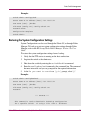
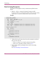
To save time when configuring the fabric parameters:
1. Configure one switch first (using the configure command)
2. Use the configUpload command to save the configuration information.
See “Saving the Switch Configuration File to a Host” on page 37.
3. Use the configdownload command to download it onto each of the
remaining switches. See “Restoring the System Configuration Settings” on
page 55.
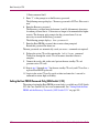
Understanding the Core PID Requirements
Core Port Identifier (PID) addressing is an option of the configure command
for 2.6.0c + and 3.0.2.g+ firmware, but not 4.x firmware. However, even if you are
configuring a Core Switch 2/64 or SAN Switch 2/32 switch, it is important to note
this requirement if you have a fabric that mixes 4.x switches with other switches.
Failing to update the Core PID addressing in non-4.x switches will result in
segmentation in a mixed fabric.
For detailed information regarding Core PID and related procedures, see
“Procedures for Updating the Core PID Format” on page 154.
For fabrics that consist of only 4.x.x firmware (Core Switch 2/64 or SAN Switch
2/32 switches), no action is required to configure the Core PID. The Core PID is
enabled by default, and this parameter cannot be changed. However, other
switches in your fabric will need to be Core PID-enabled if you mixing 2.x.x or
3.x.x. firmware with your 4.x.x firmware in a single fabric.
Mixed Fabric Requirements
To mix 2.x.x or 3.x.x switches into a fabric that contains one or more 4.x.x
switches, the following is required:
Minimum Firmware
28
■
2.x.x firmware must be 2.6.0c or later (though 2.6.1 is strongly recommended
for full functionality)
■
3.x.x firmware must be 3.0.2g or later
Fabric OS Procedures Version 3.1.x/4.1.x User Guide
Initial Configuration
Configuration Requirement
■
The Core PID must be enabled on all 2.6.0c + and 3.0.2g + switches. See
(Optional) Enabling Core PID Addressing.
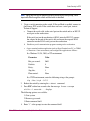
(Optional) Enabling Core PID Addressing
To enable Core PID addressing on 2.6.0c or 3.0.2g switches for the purpose of
mixing in to a 4.x.x fabric:
1. Telnet into the switch.
2. Log into the switch as admin.
3. Disable the switch by entering the switchdisable command.
4. Enter the configure command (the configure prompts display
sequentially).
5. Enter “y” after the “Fabric parameters” prompt. Be sure to use the same
configuration parameters as the rest of your fabric.
6. Enter “1” at the “Core Switch PID Format” prompt. This enables the Core
PID addressing, and allows the non-4.x switch to merge into a 4.x fabric.
7. Complete the remaining prompts or press Ctrl+D to accept the remaining
settings without completing all the prompts.
8. Be sure to use the same configuration parameters as the rest of your fabric.
9. Repeat steps 1 through 4 for all 2.6.0c or 3.0.2g switches that you want to
incorporate into the mixed fabric.
Considering Additional Fabric Configurations
In addition to the fabric configurations set through the configure command,
additional configurations can be set.
The following are some additional configurations to consider:
Set Routing
See Routing on page 65.
Track Changes
See Tracking Switch Changes on page 63.
Status Policies
See Switch Status Policies on page 58.
Fabric OS Procedures Version 3.1.x/4.1.x User Guide
29
Initial Configuration
Configure Software Features
Configure the software features (such as Fabric Watch, Zoning, and Secure Fabric
OS) for each switch. Refer to the User Guide for each software feature for
configuration information.
To save time, configure the software features on one switch, then save the
configuration file, and download it to each of the remaining switches. See “Saving
the Switch Configuration File to a Host” on page 37 and to “Restoring the System
Configuration Settings” on page 55 for more information.
30
Fabric OS Procedures Version 3.1.x/4.1.x User Guide
Initial Configuration
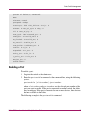
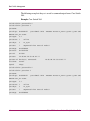
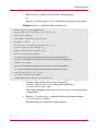
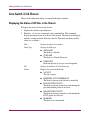
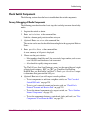
Verify Switch Function
To verify that your switch is operating correctly, display information about the
switch and port status.
To display information about the switch and port status:
1. Log into the switch as the admin user.
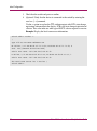
2. Enter the switchshow command at the command line. This command
displays a switch summary and a port summary.
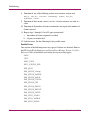
The following example displays the switchshow command.
Example:
switch:admin> switchshow
switchName:
switch
switchType:
16.2
switchState:
Online
switchMode:
Native
switchRole:
Subordinate
switchDomain:
7
switchId:
fffc07
switchWwn:
10:00:00:60:69:c0:0e:88
switchBeacon:
OFF
Zoning:
ON (cfg1)
port 0: id N2 Online
(upstream)
port
1: id N2 No_Light
port
2: id N2 No_Light
port
3: id N2 No_Light
port
4: id N2 No_Light
port
5: id N2 No_Light
port
6: id N2 No_Light
port
7: id N2 No_Light
E-Port 10:00:00:60:69:c0:0f:04 "web189"
switch:admin>
Fabric OS Procedures Version 3.1.x/4.1.x User Guide
31
Initial Configuration
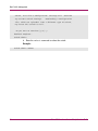
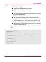
3. Check that the switch and ports are online.
4. (Optional) Verify that the device is connected to the switch by entering the
nsshow [-r] command.
Use the -r option to replace the TTL attribute output with SCR (state change
registration) information in the display. SCR is the state change registration of
a device. This value indicates what type of RSCN a device registers to receive.
Example: Display the local name server information.
switch:admin> nsshow -r
{
Type Pid COS PortName NodeName SCR
NL 2016ce; 3;21:00:00:04:cf:75:78:d2;20:00:00:04:cf:75:78:d2; 0
FC4s: FCP [SEAGATE ST318452FC 0001]
Fabric Port Name: 20:16:00:60:69:90:03:f8
N 201700; 3;21:00:00:e0:8b:05:a3:c9;20:00:00:e0:8b:05:a3:c9; 1
Fabric Port Name: 20:17:00:60:69:90:03:f8
The Local Name Server has 2 entries }
switch:admin>
32
Fabric OS Procedures Version 3.1.x/4.1.x User Guide
Initial Configuration
Connect ISLs to Switch
Refer to the switch installation guide supplied with your specific switch (the
installation guide is also available on the v3.1.x or v4.1.x Software CD) for ISL
connection and cable management information.
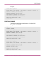
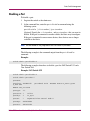
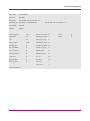
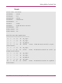
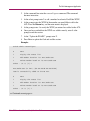
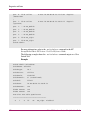
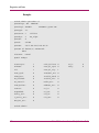
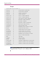
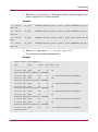
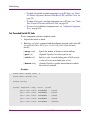
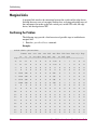
Verifying the Fabric Connectivity
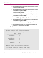
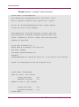
To verify that you have fabric-wide switch connectivity, display a summary of
information about the fabric.
To display a summary of information about the fabric:
1. Log into the switch as the admin user.
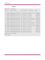
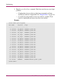
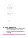
2. Enter the fabricshow command at the command line. This command
displays a summary of all the switches in the fabric.
Fabric OS Procedures Version 3.1.x/4.1.x User Guide
33
Initial Configuration
Example:
switch:admin> fabricshow
Switch ID
Worldwide Name
Enet IP Addr
FC IP Addr
Name
------------------------------------------------------------------------1: fffc01 10:00:00:60:69:80:04:5a
192.168.186.61
192.168.68.193
3: fffc03 10:00:00:60:69:10:9c:29
192.168.186.175 0.0.0.0
"switch175"
4: fffc04 10:00:00:60:69:12:14:b7
192.168.174.70
"switch70"
5: fffc05 10:00:00:60:69:45:68:04
192.168.144.121 0.0.0.0
"switch121"
6: fffc06 10:00:00:60:69:00:54:ea
192.168.174.79
192.168.68.197
"switch79"
192.168.68.194
0.0.0.0
"switch61"
7: fffc07 10:00:00:60:69:80:04:5b
192.168.186.62
8: fffc08 10:00:00:60:69:04:11:22
192.168.186.195 0.0.0.0
"switch195"
"switch62"
9: fffc09 10:00:00:60:69:10:92:04
192.168.189.197 192.168.68.198
"switch197"
10: fffc0a 10:00:00:60:69:50:05:47
192.168.189.181 192.168.68.181
"switch181"
11: fffc0b 10:00:00:60:69:00:54:e9
192.168.174.78
192.168.68.196
"switch78"
0.0.0.0
15: fffc0f 10:00:00:60:69:30:1e:16
192.168.174.73
33: fffc21 10:00:00:60:69:90:02:5e
192.168.144.120 0.0.0.0
"switch120"
"switch73"
44: fffc2c 10:00:00:60:69:c0:06:8d
192.168.144.119 0.0.0.0
"switch119"
97: fffc61 10:00:00:60:69:90:02:ed
192.168.144.123 0.0.0.0
"switch123"
98: fffc62 10:00:00:60:69:90:03:32
192.168.144.122 0.0.0.0
"switch122"
The Fabric has 15 switches
switch:admin>
34
Fabric OS Procedures Version 3.1.x/4.1.x User Guide
Initial Configuration
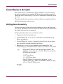
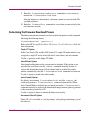
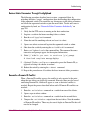
Connect Devices to the Switch
Power off all devices (to minimize Port Logins (PLOGIs)) and connect them to
the switch, according to your topology. For devices that cannot be powered off,
connect the devices, but use the portdisable command to disable the port on
the switch.
When powering the devices back on, wait for each device to complete the fabric
login before powering on the next one.
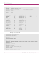
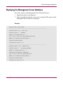
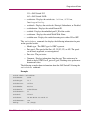
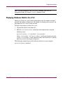
Verifying Device Connectivity
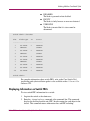
To verify that you have fabric-wide device connectivity, display the fabric-wide
device count. The number of devices listed in the Name Server (NS) should reflect
the number of devices that are connected.
To display the fabric-wide device count from a switch:
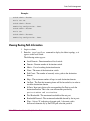
1. Log into the switch as the admin user.
2. (Optional) Enter the switchshow command to verify that the storage
devices are logged in.
3. (Optional) Enter the nsshow command to verify that the storage devices
have successfully registered with the Name Server.
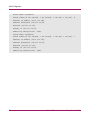
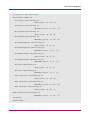
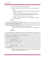
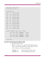
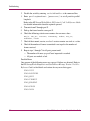
4. Enter the nsallshow [type] command at the command line. This
command displays 24-bit Fibre Channel addresses of all devices in the fabric.
type
Specify the FC-PH type code. This operand is optional. The
valid values for this operand are 0 to 255. Below are two specific
FC-PH device type codes:
8 = FCP type device
4 , 5 = FC-IP type device
Other FC-PH types are displayed in the format "x ports
supporting FC4 code," where x is the number of ports of a type,
and code is the FC-PH type code.
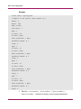
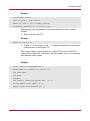
Example:
Fabric OS Procedures Version 3.1.x/4.1.x User Guide
35
Initial Configuration
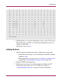
switch:admin> nsallshow
12 Nx_Ports in the Fabric {
011200 0118e2 0118e4 0118e8 0118ef 021200
0214e2 0214e4 0214e8 0214ef
}
switch:admin> nsAllShow 8
8 FCP Ports {
0118e2 0118e4 0118e8 0118ef 0214e2 0214e4 0214e8 0214ef
}
switch:admin> nsAllShow 5
2 FC-IP Ports in the Fabric {
011200 021200}
36
Fabric OS Procedures Version 3.1.x/4.1.x User Guide
Initial Configuration
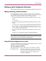
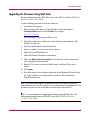
Backing up Switch Configuration Information
The following sections describe how to back up switch configuration information.
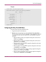
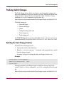
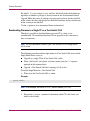
Making a Hard Copy of Switch Information
It is recommended that you make a hard copy backup of all key configuration
data, including license key information for every switch, and store it in a safe and
secure place for emergency reference. See the following procedures.
1. Print out the information from the following command and store in a secure
location:
licenseshow
2. Print out the information from the following command and store in a secure
location:
configUpload - Contains license and configuration information. Refer to
the configUpload command in the HP StorageWorks Fabric OS Version
3.1.x/4.1.x Reference Guide or the HP StorageWorks Fabric Manager Version
3.0.x User Guide for more information.
3. Print out the information from the following command and store in a secure
location:
ipaddrshow - Select option 4 to display all configured addresses.
Note: Depending on the security procedures of your company, you may want to keep
a record of the user levels and passwords for all switches in the fabric. This is sensitive
information and access to such information should be limited.
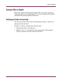
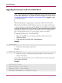
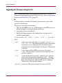
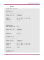
Saving the Switch Configuration File to a Host
Save all key configuration data, including license key information for every switch
and upload it to a host for emergency reference.
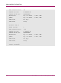
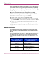
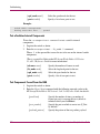
About the configupload Command
The configuration file is written as three sections, and is broken up as follows:
■
The first section
Contains the switch boot parameters. It has variables
such as the switch's name and IP address. This section
corresponds to the first few lines of output of the
configshow command.
Fabric OS Procedures Version 3.1.x/4.1.x User Guide
37
Initial Configuration
■
The second section Contains general switch configuration variables, such as
diagnostic settings, fabric configuration settings, and
SNMP settings. This section corresponds to the output of
the configshow command (after the first few lines),
although there are more lines uploaded than shown by the
command.
■
The third section
Contains zoning configuration parameters.
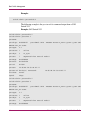
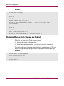
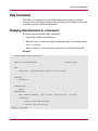
To save a backup copy of the configuration file to a host:
1. Verify that the FTP service is running on the host workstation (or on a
Windows machine).
2. Log into the switch as the admin user.
3. Enter the configupload command.
Enter the command only, then enter the options as you are prompted; or enter:
configupload ["host","user","file"[,"passwd"]]
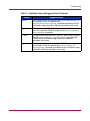
Table 2: Description of configupload Options
Option
Description
host
Specify a host name or IP address in quotation marks; for example,
“citadel” or “192.168.1.48”. The configuration file is downloaded from
this host system. This operand is optional.
user
Specify a user name in quotation marks; for example, “jdoe”. This user
name is used to gain access to the host. This operand is optional.
file
Specify a file name in quotation marks; for example, “config.txt”.
Absolute path names may be specified using forward slash (/). Relative
path names create the file in the user’s home directory on UNIX hosts,
and in the directory where the FTP server is running on a Windows
hosts. This operand is optional.
passwd
Specify a password in quotation marks. This operand is optional.
Example:
swd5:admin> configupload "citadel","jdoe","config.txt","passwd"
upload complete
switch:admin>
A message displays indicating that the upload is complete.
38
Fabric OS Procedures Version 3.1.x/4.1.x User Guide
Basic Switch Management
2
This chapter provides information on basic configuration tasks for a switch.
The following procedures are described in this chapter:
■
Switch Enable/Disable Procedures, page 40
■
Domain IDs, page 47
■
Firmware Versions, page 49
■
Switch Date and Time, page 51
■
Fabric Configuration Settings, page 53
■
Switch Names, page 57
■
Switch Status Policies, page 58
■
Tracking Switch Changes, page 63
■
Routing, page 65
■
Help Commands, page 71
■
Hexadecimal Port Diagrams, page 73
Fabric OS Procedures Version 3.1.x/4.1.x User Guide
39
Basic Switch Management
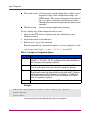
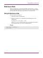
Switch Enable/Disable Procedures
The following sections describe how to disable and enable a switch.
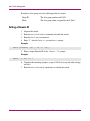
Disabling a Switch
To disable a switch:
1. Log into the switch as the admin user.
2. Enter the switchdisable command at the command line. All Fibre
Channel ports on the switch are taken offline. If the switch was part of a
fabric, the fabric reconfigures.
Example:
switch:admin> switchdisable
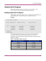
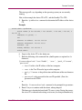
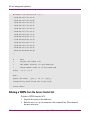
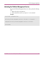
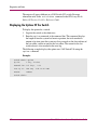
Enabling a Switch
To enable a switch:
1. Log into the switch as the admin user.
2. Enter the switchenable command at the command line.
All Fibre Channel ports that passed the POST test are enabled. If the switch was
part of a fabric, it rejoins the fabric.
Example:
switch:admin> switchenable
10 switch:admin> 9
8
7
6
5
4
3
2
1
fabric: Principal switch
fabric: Domain 1
switch:admin>
40
Fabric OS Procedures Version 3.1.x/4.1.x User Guide
Basic Switch Management
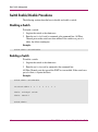
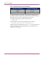
Disabling a Port
To disable a port:
1. Log into the switch as the admin user.
2. At the command line, enter the portdisable command using the
following syntax:
portdisable [slotnumber]/portnumber
(Optional) Specify the slotnumber and portnumber that you want to
disable. If the port is connected to another switch, the fabric may reconfigure.
If the port is connected to one or more devices, these devices are no longer
available to the fabric.
Note: The slot number is only required for the Core Switch 2/64 switch.
The following example is the command output from the portdisable
command.
Example:
switch:admin> portdisable 4
The following examples show how to disable a port for SAN Switch 2/32 and a
Core Switch 2/64.
Example: SAN Switch 2/32
switch:admin> portdisable 4
switch:admin> portshow 4
portName:
portFlags: 0x300082d7
U_PORT SEG
portLbMod: 0x10
PRESENT ACTIVE E_PORT G_PORT
MENTED CBL_LB LOGIN
portType:
4.1
portState: 1
Online
portPhys:
6
In_Sync
portScn:
7
Segmented Flow control mode 0
portRegs:
0x81050000
portData:
0x11efc2d0
Fabric OS Procedures Version 3.1.x/4.1.x User Guide
41
Basic Switch Management
portId:
021500
portWwn:
20:05:00:60:69:c0:06:71
portWwn of device(s) connected:
Distance:
normal
Speed:
2Gbps
20:05:00:60:69:c0:06:71
Interrupts:
227
Link_failure: 0
Frjt:
0
Unknown:
28
Loss_of_sync: 7
Fbsy:
0
Lli:
63
Loss_of_sig:
Proc_rqrd:
150
Protocol_err: 0
Timed_out:
0
Invalid_word: 0
Rx_flushed:
0
Invalid_crc:
0
Tx_unavail:
0
Delim_err:
0
Free_buffer:
0
Address_err:
0
Overrun:
0
Lr_in:
14
Suspended:
0
Lr_out:
14
Parity_err:
0
Ols_in:
7
Ols_out:
7
0
switch:admin>
Example: Core Switch 2/64
switch:admin> portdisable 1/5
switch:admin> portshow 1/5
portName:
portDisableReason: None
portCFlags: 0x1
portFlags: 0xc228057 PRESENT ACTIVE E_PORT G_PORT U_PORT LOGIN LED ACCEPT
portType: 4.1
portState: 2 Offline
portPhys: 6 In_Sync
portScn: 5 E_Port Trunk master port,
portId: 010500
portWwn: 20:05:00:60:69:80:03:32
42
Fabric OS Procedures Version 3.1.x/4.1.x User Guide
Basic Switch Management
portWwn of device(s) connected:
None
Distance: normal
portSpeed: N2Gbps
Interrupts: 1086 Link_failure: 0 Frjt: 0
Unknown: 0 Loss_of_sync: 0 Fbsy: 0
Lli: 0 Loss_of_sig: 0
Proc_rqrd: 1086 Protocol_err: 0
Timed_out: 0 Invalid_word: 0
Rx_flushed: 0 Invalid_crc: 0
Tx_unavail: 0 Delim_err: 0
Free_buffer: 0 Address_err: 0
Overrun: 0 Lr_in: 0
Suspended: 0 Lr_out: 0
Parity_err: 0 Ols_in: 0
2_parity_err: 0 Ols_out: 0
CMI_bus_err: 0
switch:admin>
Enabling a Port
To enable a port:
1. Log into the switch as the admin user.
2. Enter the portenable command at the command line, using the following
syntax:
portenable [slotnumber]/portnumber
where slotnumber and portnumber are the slot and port number of the
port you want to enable. If the port is connected to another switch, the fabric
may reconfigure. If the port is connected to one or more devices, these devices
become available to the fabric.
The following example is the portenable command.
Fabric OS Procedures Version 3.1.x/4.1.x User Guide
43
Basic Switch Management
Example:
switch:admin> portenable 4
The following example is the portenable command output from a SAN
Switch 2/32.
Example: SAN Switch 2/32
switch:admin> portenable 4
switch:admin> portshow 4
portName:
portFlags: 0x300082d7
portLbMod: 0x10
PRESENT ACTIVE E_PORT G_PORT U_PORT SEG
MENTED CBL_LB LOGIN
portType:
4.1
portState: 1
Online
portPhys:
6
In_Sync
portScn:
7
Segmented Flow control mode 0
portRegs:
0x81050000
portData:
0x11efc2d0
portId:
021500
portWwn:
20:05:00:60:69:c0:06:71
portWwn of device(s) connected:
Distance:
normal
Speed:
2Gbps
20:05:00:60:69:c0:06:71
switch:admin> portenable 4
switch:admin> portshow 4
portName:
portFlags: 0x300082d7
portLbMod: 0x10
PRESENT ACTIVE E_PORT G_PORT U_PORT SEG
MENTED CBL_LB LOGIN
portType:
4.1
portState: 1
Online
portPhys:
6
In_Sync
portScn:
7
Segmented Flow control mode 0
portRegs:
0x81050000
44
Fabric OS Procedures Version 3.1.x/4.1.x User Guide
Basic Switch Management
portData:
0x11efc2d0
portId:
021500
portWwn:
20:05:00:60:69:c0:06:71
portWwn of device(s) connected:
Distance:
normal
Speed:
2Gbps
20:05:00:60:69:c0:06:71
Interrupts:
227
Link_failure: 0
Frjt:
0
Unknown:
28
Loss_of_sync: 7
Fbsy:
0
Lli:
63
Loss_of_sig:
Proc_rqrd:
150
Protocol_err: 0
Timed_out:
0
Invalid_word: 0
Rx_flushed:
0
Invalid_crc:
0
Tx_unavail:
0
Delim_err:
0
Free_buffer:
0
Address_err:
0
Overrun:
0
Lr_in:
14
Suspended:
0
Lr_out:
14
Parity_err:
0
Ols_in:
7
Ols_out:
7
0
switch:admin>
Fabric OS Procedures Version 3.1.x/4.1.x User Guide
45
Basic Switch Management
The following example is the portenable command output from a Core Switch
2/64.
Example: Core Switch 2/64
switch:admin> portenable 4
switch:admin> portshow 4
portName:
portFlags: 0x300082d7
portLbMod: 0x10
PRESENT ACTIVE E_PORT G_PORT U_PORT SEG
MENTED CBL_LB LOGIN
portType:
4.1
portState: 1
Online
portPhys:
6
In_Sync
portScn:
7
Segmented Flow control mode 0
portRegs:
0x81050000
portData:
0x11efc2d0
portId:
021500
portWwn:
20:05:00:60:69:c0:06:71
portWwn of device(s) connected:
Distance:
normal
Speed:
2Gbps
20:05:00:60:69:c0:06:71
switch:admin> portenable 4
switch:admin> portshow 4
portName:
portFlags: 0x300082d7
portLbMod: 0x10
PRESENT ACTIVE E_PORT G_PORT U_PORT SEG
MENTED CBL_LB LOGIN
portType:
4.1
portState: 1
Online
portPhys:
6
In_Sync
portScn:
7
Segmented Flow control mode 0
portRegs:
0x81050000
46
Fabric OS Procedures Version 3.1.x/4.1.x User Guide
Basic Switch Management
Domain IDs
Domain IDs are assigned dynamically when a switch is enabled. However, the
Domain ID can be set manually in order to control the number or to resolve a
Domain ID conflict when merging fabrics.
Display a Current List of Domain IDs
1. Log into a switch.
2. Enter the fabricshow command.
Fabric information is displayed, including the Domain ID (D_ID).
Example:
switch:admin> fabricshow
Switch ID Worldwide Name Enet IP Addr FC IP Addr Name
------------------------------------------------------------------------3: fffc43 10:00:00:60:69:10:60:1f 192.168.64.187 0.0.0.0 "sw187"
2: fffc42 10:00:00:60:69:00:05:91 192.168.64.60 192.168.65.60 "sw60"
1: fffc41 10:00:00:60:69:00:02:0b 192.168.64.180 192.168.65.180 >"sw180"
0: fffc40 10:00:00:60:69:00:06:56 192.168.64.59 192.168.65.59 "sw5"
The Fabric has 4 switches
Group ID Token
----------------0: fffb01 40:05:00:00:10:00:00:60:69:00:00:15
The fields in the fabricshow command are described as follows:
Switch ID
The switch Domain_ID and embedded port D_ID.
World Wide Name
The switch WWN.
Enet IP Addr
The switch ethernet IP address.
FC IP Addr
The switch FC IP address.
Name
The switch symbolic name. An arrow (>) indicates the
principal switch.
Fabric OS Procedures Version 3.1.x/4.1.x User Guide
47
Basic Switch Management
If multicast alias groups exist, the following fields are shown:
Group ID
The alias group number and D_ID.
Token
The alias group token (assigned by the N_Port).
Setting a Domain ID
1. Log into the switch.
2. Enter the switchdisable command to disable the switch.
3. Enter the configure command.
4. Enter “Y” after the Fabric parameters prompt:
Example:
Fabric parameters (yes, y, no, n): [no] y
5. Enter a unique Domain ID at the Domain ID prompt:
Example:
Domain: (1..239) [1] 3
6. Complete the remaining prompts (or press Ctrl+D to accept the other settings
and exit).
7. Enter the switchenable command to re-enable the switch.
48
Fabric OS Procedures Version 3.1.x/4.1.x User Guide
Basic Switch Management
Firmware Versions
Different StorageWorks Fibre Channel switches run different versions of Fabric
OS firmware. The following table describes the switch series and the
corresponding firmware:
Table 3: Switch Series and Applicable Firmware
Switch Type
Correct Firmware
StorageWorks 1 Gb SAN
switches
Fabric OS 2x
SAN Switch 2/8 EL and
SAN Switch 2/16 series
Fabric OS 3x
SAN Switch 2/32 switch
Fabric OS 4x
Core Switch 2/64 switch
Fabric OS 4x
Displaying the Firmware Version and Information
To display the firmware version:
1. Log into the switch as the admin user (refer to “Switch Login” on page 21).
2. Enter the version command at the command line. This command displays
the Kernel version, Fabric OS release number, and other information about the
firmware.
The following example shows the firmware version information on a Core Switch
2/64.
Example: Core Switch 2/64
switch:admin> version
Kernel:
2.4.2
Fabric OS:
v4.1
Made on:
Sun Jan 12 01:09:45 2003
Flash:
Sun Jan 12 13:25:49 2003
BootProm:
3.1.18
switch:admin>
The following information is displayed in the version command:
Kernel
Displays the version of switch kernel operating system
Fabric OS Procedures Version 3.1.x/4.1.x User Guide
49
Basic Switch Management
Fabric OS
Displays the version of switch Fabric OS
Made on
Displays the build date of firmware running in switch
Flash
Displays the build date of firmware stored in flash proms
BootProm
Displays the version of the firmware stored in the boot PROM
Usually the Made on and Flash dates are the same, since the switch starts running
flash firmware at power-on. However, in the time period between
firmwareDownload and the next reboot, the dates can differ.
3. Enter the firmwareShow command.
Use this command to display the Fabric OS versions on primary and
secondary partitions on the local CP and on the remote CP. This command
identifies the status for each CP as Active or Standby, and will also identify
the slot number for each CP.
If there is only one CP available, the command displays the Fabric OS
versions for the primary and secondary partitions on that CP.
Example: SAN Switch 2/32
switch232:admin> firmwareshow
Local CP (Slot 5, CP0): Active
Primary partition: v4.0.2
Secondary Partition: v4.0.2
Remote CP is Non-redundant.
switch232:admin>
Example: Core Switch 2/64
switch264:admin> firmwareshow
Local CP (Slot 5, CP0): Active
Primary partition: v4.0.2
Secondary Partition: v4.0.2
Remote CP (Slot 6, CP1): Standby
Primary partition: v4.0.2
Secondary Partition: v4.0.2
switch264:admin>
50
Fabric OS Procedures Version 3.1.x/4.1.x User Guide
Basic Switch Management
Switch Date and Time
All switches maintain current date and time in non-volatile memory. Date and
time are used for logging events. Switch operation does not depend on the date
and time; a switch with an incorrect date and time value still functions properly.
Note: This command is disabled when the security feature is enabled. With security
enabled you can only view the current setting.
Setting the Switch Date and Time
To set the date and time of a switch:
1. Log into the switch as the admin user.
2. At the command line, enter the date command using the following syntax:
date “MMDDhhmmYY”
The values represent the following:
— MM is the month, valid values are 01-12.
— DD is the date, valid values are 01-31.
— hh is the hour, valid values are 00-23.
— mm is minutes, valid values are 00-59.
— YY is the year, valid values are 00-99.
Note: Year values greater than 69 are interpreted as 1970—1999, year values less
than 70 are interpreted as 2000—2069. The date function does not support daylight
savings time or time zones.
Example:
switch:admin> date "0505215089"
Fri May
5 21:50:00 UTC 1989
switch:admin>
Fabric OS Procedures Version 3.1.x/4.1.x User Guide
51
Basic Switch Management
Synchronize Local Time with an External Source
Use this procedure to synchronize the local time of the Principal or Primary FCS
switch to an external NTP server.
1. Log in as admin.
2. Enter the tsclockserver [ipaddr] command
where ipaddr is the IP address of the NTP server. The ipaddr specified
should be the IP address of an NTP server and should be accessible from the
switch. This operand is optional; by default this value is LOCL.
Example:
switch:admin> tsclockserver
LOCL
switch:admin> tsclockserver "132.163.135.131"
switch:admin> tsclockserver
132.163.135.131
switch:admin>
52
Fabric OS Procedures Version 3.1.x/4.1.x User Guide
Basic Switch Management
Fabric Configuration Settings
It is important to have consistent system configuration settings since inconsistent
parameters among switches in the same fabric can cause fabric segmentation. To
troubleshoot a fabric segmentation issue, refer to “Restoring the System
Configuration Settings” on page 55.
The following parameters are included in the System Configuration Settings:
■
Fabric Parameters
■
Virtual Channel Settings
■
Zoning Operation Parameters
■
Rscn Transmission Mode
■
NS Pre-zoning Mode
■
Arbitrated Loop Parameters
■
System Services
■
Portlog Events Enable
Displaying the Fabric Configuration Settings
To display and check system configuration settings, perform the following
procedure.
1. Log into the switch as the admin user.
2. Enter the configshow command at the command line. The system
configuration settings appear.
switch:admin> configshow
RSCN.end-device.TransmissionMode:0
alpaList:1
boot.device:fei
boot.file:/usr/switch/firmware
boot.gateway.ipa:192.168.147.172
boot.ipa:192.168.147.172:ffffff00
boot.mac:10:00:00:60:69:80:04:22
boot.name:ter172
boot.server.ipa:
Fabric OS Procedures Version 3.1.x/4.1.x User Guide
53
Basic Switch Management
boot.server.name:host
boot.user:user
diag.loopID:125
diag.mode.burnin:0
diag.mode.burnin.1.name:switchess.sh
diag.mode.burnin.10.name:switchess.sh
diag.mode.burnin.2.name:switchess.sh
diag.mode.burnin.3.name:switchess.sh
diag.mode.burnin.4.name:switchess.sh
diag.mode.burnin.7.name:switchess.sh
diag.mode.burnin.8.name:switchess.sh
diag.mode.burnin.9.name:switchess.sh
diag.mode.burnin.level:0
diag.mode.esd:0
diag.mode.lab:28
switch:admin>
Note: System configuration parameters vary depending on switch model and
configuration.
Backing Up the System Configuration Settings
Keep a backup file of the system configuration settings in the event that the
configurations are lost or unintentional changes are made.
System Configurations can be saved through the Fabric OS, or through Fabric
Manager. To back up or restore system configuration settings through Fabric
Manager, refer to the HP StorageWorks Fabric Manager Version 3.0.x User
Guide.
To upload a backup copy of the configuration settings to a host computer:
1. Verify that the FTP service is running on the host workstation.
2. Log into the switch as the admin user.
3. At the command line, enter the configupload command. The command
becomes interactive and you are prompted for the required information.
54
Fabric OS Procedures Version 3.1.x/4.1.x User Guide
Basic Switch Management
Example:
switch:admin> configupload
Server Name or IP Address [host]: 192.168.15.42
User Name [user]: johndoe
File Name [config.txt]: config-switch.txt
Password:xxxxx
configuration complete
switch:admin>
Restoring the System Configuration Settings
System Configurations can be saved through the Fabric OS, or through Fabric
Manager. To back up or restore system configuration settings through Fabric
Manager, refer to the HP StorageWorks Fabric Manager Version 3.0.x User
Guide.
To restore the system configuration settings from a backup:
1. Verify that the FTP service is running on the host workstation.
2. Log into the switch as the admin user.
3. Shut down the switch by entering the switchdisable command.
4. Enter the configdownload command at the command line. The command
becomes interactive and you are prompted for the required information.
5. At the Do you want to continue [y/n] prompt, select “y”.
Example:
switch:admin> configdownload
Server Name or IP Address [host]: 192.168.15.42
User Name [user]: johndoe
File Name [config.txt]: config-switch.txt
Password:
*** CAUTION ***
This command is used to download a backed-up configuration
for a specific switch.
If using a file
Fabric OS Procedures Version 3.1.x/4.1.x User Guide
from a
different
55
Basic Switch Management
switch, this file's configuration
any current switch settings.
file, which was uploaded
settings will
override
Downloading a configuration
from a different type of switch,
may cause this switch to fail.
Do you want to continue [y/n]: y
download complete..
switch:admin>
6. Enter the reboot command to reboot the switch.
Example:
switch:admin> reboot
56
Fabric OS Procedures Version 3.1.x/4.1.x User Guide
Basic Switch Management
Switch Names
Switches can be identified by IP address, Domain ID, WWN, or customized
switch name.
Changing a Switch Name
To change the name of a switch:
1. Log into the switch as the admin user.
2. Enter the switchname command at the command line, using the following
syntax:
switchname “newname”
Where newname is the new name for the switch. Switch names can be up to 19
characters in length, must begin with a letter, and can contain letters, numbers, or
the underscore character.
Note: This command is disabled when the security feature is enabled. With security
enabled, you can only view the current setting unless it is run on the Primary Fabric
Configuration Server (FCS) switch.
Quotation marks must be used to identify the new name.
Example:
switch:admin> switchname "switch62"
Committing configuration...
Done.
switch62:admin>
Fabric OS Procedures Version 3.1.x/4.1.x User Guide
57
Basic Switch Management
Switch Status Policies
For detailed information about setting policy parameters, refer to the HP
StorageWorks Fabric Watch Version 3.1.x/4.1.x User Guide.
The policy parameter determines the number of failed or non-operational units for
each contributor that will trigger a status change in the switch.
Each parameter can be adjusted so that a specific threshold must be reached
before that parameter changes the overall status of a switch to MARGINAL or
DOWN. For example, if the FaultyPorts DOWN parameter is set to 3, the status of
the switch will change if 3 ports fail. Only one policy parameter needs to pass the
MARGINAL or DOWN threshold to change the overall status of the switch.
There are seven parameters that determine the status of a switch:
■
Number of faulty ports
■
Missing GBICs
■
Power supply status
■
Temperature in enclosure
■
Fan speed
■
Port status
■
ISL status
Viewing the Policy Threshold Values
To view the switch status policy threshold values:
1. Log into the switch as the admin user.
2. Enter the switchstatuspolicyshow command at the command line.
58
Fabric OS Procedures Version 3.1.x/4.1.x User Guide
Basic Switch Management
Example:
switch:admin> switchstatuspolicyshow
The current overall switch status policy parameters:
Down
Marginal
---------------------------------FaultyPorts
2
1
MissingSFPs
0
0
PowerSupplies
2
1
Temperatures
2
1
Fans
2
1
PortStatus
0
0
ISLStatus
2
1
switch:admin>
Configuring the Policy Threshold Values
To set the switch status policy threshold values:
1. Log into the switch as the admin user.
2. Enter the switchstatuspolicyset command at the command line.
First, the current switch status policy parameter values are displayed, then you
are prompted to enter values for each DOWN and MARGINAL threshold
parameter:
— Enter the number of faulty ports required to change the switch status to
DOWN and click Enter.
— Enter the number of faulty ports required to change the switch status to
MARGINAL and click Enter.
— Enter the number of missing GBICs required to change the switch status
to DOWN and click Enter.
— Enter the number of missing GBICs required to change the switch status
to MARGINAL and click Enter.
— Enter the number of bad Power Supply warnings required to change the
switch status to DOWN and click Enter.
— Enter the number of bad Power Supply warnings required to change the
switch status to MARGINAL and click Enter.
Fabric OS Procedures Version 3.1.x/4.1.x User Guide
59
Basic Switch Management
— Enter the number of temperature warnings required to change the switch
status to DOWN and click Enter.
— Enter the number of temperature warnings required to change the switch
status to MARGINAL and click Enter.
— Enter the number of fan speed warnings required to change the switch
status to DOWN and click Enter.
— Enter the number of fan speed warnings required to change the switch
status to MARGINAL and click Enter.
— Enter the number of port down warnings required to change the switch
status to DOWN and press the Enter.
— Enter the number of port down warnings required to change the switch
status to MARGINAL and click Enter.
— Enter the number of ISLstatus down warnings required to change the
switch status to DOWN and click Enter.
— Enter the number of ISLstatus down warnings required to change the
switch status to MARGINAL and click Enter.
Example:
switch:admin> switchstatuspolicyset
To change the overall switch status policy parameters
The current overall switch status policy parameters:
Down
Marginal
---------------------------------FaultyPorts
2
1
MissingSFPs
0
0
PowerSupplies
2
1
Temperatures
2
1
Fans
2
1
PortStatus
0
0
ISLStatus
2
1
Note that the value, 0, for a parameter, means that i
NOT used in the calculation.
** In addition, if the range of settable values in the
** the policy parameter is NOT applicable to the switch
60
Fabric OS Procedures Version 3.1.x/4.1.x User Guide
Basic Switch Management
** Simply hit the Return key.
The minimum number of
FaultyPorts contributing to
DOWN status: (0..64) [2]
FaultyPorts contributing to
MARGINAL status: (0..64) [1]
MissingSFPs contributing to
DOWN status: (0..64) [0]
MissingSFPs contributing to
MARGINAL status: (0..64) [0]
Bad PowerSupplies contributing to
DOWN status: (0..4) [2]
Bad PowerSupplies contributing to
MARGINAL status: (0..4) [1]
Bad Temperatures contributing to
DOWN status: (0..6) [2]
Bad Temperatures contributing to
MARGINAL status: (0..6) [1]
Bad Fans contributing to
DOWN status: (0..3) [2]
Bad Fans contributing to
MARGINAL status: (0..3) [1]
Down PortStatus contributing to
DOWN status: (0..64) [0]
Down PortStatus contributing to
MARGINAL status: (0..64) [0]
down ISLStatus contributing to
DOWN status: (0..64) [2]
down ISLStatus contributing to
MARGINAL status: (0..64) [1]
No change
switch:admin>
Fabric OS Procedures Version 3.1.x/4.1.x User Guide
61
Basic Switch Management
3. Verify the threshold settings you have configured for each parameter. Enter
the switchstatuspolicyshow command to view your current switch
status policy configuration.
Note: By setting the DOWN and MARGINAL value for a parameter to 0,0, that
parameter is no longer used in setting the overall status for the switch.
62
Fabric OS Procedures Version 3.1.x/4.1.x User Guide
Basic Switch Management
Tracking Switch Changes
The Track Change feature allows you to keep a record of specific changes that
may not be considered switch events, but may be useful. The output from the track
changes feature is dumped to the error log for the switch. Use the errdump
command or errshow command to view the error log.
Items in the error log created from the Track changes feature are labeled TRACK.
Trackable changes are:
— Successful login
— Unsuccessful login
— Logout
— Config file change from task
— Track-changes on
— Track-changes off
An SNMP-TRAP mode can also be enabled. Refer to the trackchangeshelp
command in the HP StorageWorks Fabric OS Version 3.1.x/4.1.x Reference Guide.
Enabling the Track Changes Feature
To enable the track changes feature:
1. Log into the switch as the admin user.
2. Enter the trackchangesset 1 command at the command line to enable
the track changes feature.
A prompt is displayed verifying that the track changes feature is on.
Example:
switch:admin> trackchangesset 1
Committing configuration...done.
switch:admin>
The output from the track changes feature is dumped to the error log for the
switch. Use the errdump command or errshow command to view the error
log.
Items in the error log created from the Track changes feature are labeled TRACK.
Fabric OS Procedures Version 3.1.x/4.1.x User Guide
63
Basic Switch Management
Example:
switch:admin> errdump
Error 07
-------0x17ef (fabos): Mar 24 11:10:27
Switch: 1, Info TRACK-CONFIG_CHANGE, 4, Config file change from
task:TRACKIPC
Error 06
-------0x4e7 (fabos): Mar 24 11:10:24
Switch: 1, Info TRACK-TRACK_ON, 4, Track-changes on
Displaying Whether Track Changes are Enabled
To display the status of the Track Changes feature:
1. Log into the switch as the admin user.
2. At the command line, enter the trackchangesshow command.
The status of the track changes feature is displayed as either on or off. This also
displays whether the track changes feature is configured to send SNMP traps.
Example:
switch:admin> trackchangesshow
Track changes status: ON
Track changes generate SNMP-TRAP: NO
switch:admin>
64
Fabric OS Procedures Version 3.1.x/4.1.x User Guide
Basic Switch Management
Routing
In Order Delivery
In a stable fabric, frames are always delivered in order, even when the traffic
between switches is shared among multiple paths. However, when topology
changes occur in the fabric (for instance, a link goes down), traffic is rerouted
around the failure. When topology changes occur, some frames could be delivered
out of order.
The default behavior is to automatically enable out-of-order delivery of frames
during fabric topology changes; this enables fast rerouting after a fabric topology
change. See “Forcing In-order Delivery of Frames” on page 65 to change the
default routing settings during topology changes.
Dynamic Load Sharing
Routing is generally based on the incoming port and the destination domain. This
means that all the traffic coming in from a port (either E_Port or Fx_Port),
directed to the same remote domain, is routed through the same output E_Port. To
optimize fabric routing, when there are multiple equivalent paths to a remote
switch, traffic is shared among all the paths. Load sharing is recomputed when a
switch is booted up or every time a change in the fabric occurs. A change in the
fabric is defined as an E_Port going up or down, or an Fx_Port going up or down.
See “Using Dynamic Load-Sharing” on page 66.
Forcing In-order Delivery of Frames
To force in-order delivery of frames during fabric topology changes:
1. Log into the switch as the admin user.
2. At the command line, enter the iodset command.
Example:
switch:admin> iodset
done.
switch:admin>
Note: This command can cause a delay in the establishment of a new path when a
topology change occurs, and should be used with care.
Fabric OS Procedures Version 3.1.x/4.1.x User Guide
65
Basic Switch Management
Restoring In-order Delivery of Frames
To restore the default In-order delivery setting (which allows frames to be
delivered out-of-order during topology changes for faster delivery):
1. Log into the switch as the admin user.
2. Enter the iodreset command at the command line.
Example:
switch:admin> iodreset
done.
switch:admin>
Using Dynamic Load-Sharing
Optimal load sharing is rarely achieved with DLS disabled. If DLS is turned on
(using dlsset), routing changes can affect working ports. For example, if an
Fx_Port goes down, another Fx_Port may be rerouted from one E_Port to a
different E_Port. The switch minimizes the number of routing changes, but some
are necessary in order to achieve optimal load sharing.
If DLS is turned off (using dlsreset), load sharing is performed only at boot
time or when an Fx_Port comes up.
1. Log in to the switch as admin.
2. Enter the dlsshow command to view the current DLS setting.
One of the following messages appears:
— DLS is set The DLS option is turned on. Load sharing is reconfigured
with every change in the fabric.
— DLS is not set The DLS option is turned off. Load sharing is only
reconfigured when the switch is rebooted or an Fx_Port comes up.
3. Enter the dlsSet command to enable Dynamic Load Sharing when a
fabric change occurs.
4. Enter the dlsReset command to disable Dynamic Load Sharing.
Load sharing is performed only at boot time or when an Fx_Port comes up.
66
Fabric OS Procedures Version 3.1.x/4.1.x User Guide
Basic Switch Management
Example:
switch:admin> dlsshow
DLS is not set
switch:admin> dlsset
Committing configuration...done.
switch:admin> dlsshow
DLS is set
switch:admin> dlsreset
Committing configuration...done.
Viewing Routing Path Information
1. Log in as admin.
2. Enter the topologyShow command to display the fabric topology, as it
appears to the local switch.
The following entries appear:
■
Local Domain - Domain number of local switch.
■
Domain - Domain number of destination switch.
■
Metric - Cost of reaching destination domain.
■
Name - The name of the destination switch.
■
Path Count - The number of currently active paths to the destination
domain.
■
Hops - The maximum number of hops to reach destination domain.
■
Out Port - The Port that incoming frame will be forwarded to, in order to
reach the destination domain.
■
In Ports- Input ports that use the corresponding Out Port to reach the
destination domain. This is the same information provided by
portrouteshow and urouteshow.
■
Total Bandwidth - The maximum bandwidth of the out port.
■
Bandwidth Demand - The maximum bandwidth demand by the in ports.
■
Flags - Always 'D', indicating a dynamic path. A dynamic path is
discovered automatically by the FSPF path selection protocol.
Fabric OS Procedures Version 3.1.x/4.1.x User Guide
67
Basic Switch Management
Example:
switch:admin> topologyshow
2 domains in the fabric; Local Domain ID: 1
Domain: 6
Metric: 500
Name: switch
Path Count: 4
Hops: 1
Out Port: 60
In Ports: None
Total Bandwidth: 2 Gbps
Bandwidth Demand: 0 %
Flags: D
Hops: 1
Out Port: 61
In Ports: None
Total Bandwidth: 2 Gbps
Bandwidth Demand: 0 %
Flags: D
Hops: 1
Out Port: 62
In Ports: None
Total Bandwidth: 2 Gbps
Bandwidth Demand: 0 %
Flags: D
Hops: 1
Out Port: 58
In Ports: None
Total Bandwidth: 2 Gbps
Bandwidth Demand: 0 %
Flags: D
3. Enter the urouteshow [slotnumber/][portnumber][,
domainnumber] command to display unicast routing information.
68
Fabric OS Procedures Version 3.1.x/4.1.x User Guide
Basic Switch Management
The following entries appear:
■
Local Domain - Domain number of local switch.
■
In Ports - Port from which a frame is received.
■
Domain - Destination domain of incoming frame.
■
Out Port - The Port that incoming frame will be forwarded to, in order to
reach the destination domain.
■
Metric - Cost of reaching destination domain.
■
Hops - The maximum number of hops to reach destination domain.
■
Flags -Indicates if route is dynamic (D) or static (S). A dynamic route is
discovered automatically by the FSPF path selection protocol. A static
route is assigned using the command urouteconfig.
■
Next (Dom, Port) - Domain and port number of the next hop. These are
the domain number and the port.
Example: The example below displays the routing information of all the active
ports:
:
switch:admin> urouteshow
Local Domain ID: 3
In Port Domain Out Port Metric Hops Flags Next (Dom, Port)
-------------------------------------------------------------------------0 1 11 1000 1 D 1,0
11 2 0 1500 2 D 4,0
4 0 500 1 D 4,0
16 1 27 1000 1 D 1,1
27 2 16 1500 2 D 4,16
4 0 500 1 D 4,0
Fabric OS Procedures Version 3.1.x/4.1.x User Guide
69
Basic Switch Management
Example: The example below displays the routing information for port 11 on slot 1
.
switch:admin> urouteshow 1/11
Local Domain ID: 3
In Port Domain Out Port Metric Hops Flags Next (Dom, Port)
-------------------------------------------------------------------------11 2 16 1500 2 D 4,16
4 16 500 1 D 4,16
Example: The example below displays the routing information of port 11 to
domain 4 only:
switch:admin> urouteshow 1/11, 4
Local Domain ID: 3
In Port Domain Out Port Metric Hops Flags Next (Dom, Port)
-------------------------------------------------------------------------11 4 16 500 1 D 4,16
70
Fabric OS Procedures Version 3.1.x/4.1.x User Guide
Basic Switch Management
Help Commands
Each Fabric OS command provides Help information that displays what the
command does, explains the possible operands, displays the command level, and
sometimes provides additional information.
Displaying Help Information for a Command
To display help information about a command:
1. Log into the switch as the admin user.
2. Enter the help command using the following syntax at the command line:
help command
where command is the name of the command you would like help with.
Example:
switch:admin> help configure
Administrative Commands
configure(1m)
NAME
configure - change system configuration settings
SYNOPSIS
configure
AVAILABILITY
admin
DESCRIPTION
This command changes
some
system
configuration
settings,
including:
o Arbitrated loop settings
o Switch fabric settings
<output truncated>
Fabric OS Procedures Version 3.1.x/4.1.x User Guide
71
Basic Switch Management
Additional Help Topics
The help command lists most of the files. There are also commands that provide
additional help files for specific topics. The following is not a complete list.
For example:
72
■
diagHelp—Print diagnostic help information.
■
fwHelp—Print Fabric Watch help information.
■
licenseHelp—Print license help information.
■
perfHelp—Print Performance Monitoring help information.
■
routeHelp—Print routing help information.
■
trackChangesHelp—Print Track Changes help information.
Fabric OS Procedures Version 3.1.x/4.1.x User Guide
Basic Switch Management
Hexadecimal Port Diagrams
Many of the commands, such as bcastshow, portLogShow, and
portLogDump return port diagrams in hexadecimal format.
Reading Hexadecimal Port Diagrams
The following example shows the bcastshow command and a member port list,
member ISL port list, and static ISL port list in hexidecimal format.
Example:
switch:admin> bcastshow
Group
Member Ports
Member ISL Ports
Static ISL Ports
---------------------------------------------------------------256
0x00000000
0x00000000
0x00000000
0x00000000
0x00000000
0x00000000
0x00000001
0x00000000
0x00000000
0x00012083
switch:admin>
To read the hexadecimal port diagrams, they must be converted into binary
notation. Each hexadecimal value represents four binary values. Each
hexadecimal value is converted into a group of four binary values that represent
four ports, as follows:
Table 4: Hexidecimal to binary conversions
Hex value = Binary value
Hex value = Binary value
0 = 0000
8 = 1000
1 = 0001
9 = 1001
2 = 0010
A = 1010
3 = 0011
B = 1011
4 = 0100
C = 1100
Fabric OS Procedures Version 3.1.x/4.1.x User Guide
73
Basic Switch Management
Table 4: Hexidecimal to binary conversions (Continued)
Hex value = Binary value
Hex value = Binary value
5 = 0101
D = 1101
6 = 0110
E = 1110
7 = 0111
F = 1111
Once the Hexadecimal is converted into a binary bit map, each bit represents a
port, where a value of 1 means yes and a value of 0 means no. The bit map is read
from right to left, that is, the least significant bit represents port 0.
For example, if the member port value is displayed in hex as:
0x00012083
This corresponds to a binary bit map of the member ports as follows:
0000 0000 0000 0001 0010 0000 1000 0011
This bit map displays the member ports as port 0, 1, 7, 13, and 16. Note that each
switch has an internal port (in the example above, port 16) which is always a
member of a broadcast group.
74
Fabric OS Procedures Version 3.1.x/4.1.x User Guide
Firmware Download
3
This chapter provides information on upgrading firmware on the StorageWorks
2 Gb SAN switches using Web Tools and FOS CLI.
This chapter provides the following information:
■
About Firmware Downloads, page 76
■
Understanding the Dual-CP Firmware Upgrade Process, page 76
■
Non-Disruptive Firmware Activation, page 77
■
The Firmware Upgrade Process, page 78
■
Upgrading the Firmware on the SAN Switch 2/32, page 78
■
Upgrading the Firmware on the Core Switch 2/64, page 80
■
Customizing the Firmware Download Process, page 83
■
Upgrading the Firmware Using Web Tools, page 87
■
Upgrading the Firmware Using the CLI, page 88
■
Frequently Asked Questions, page 89
Fabric OS Procedures Version 3.1.x/4.1.x User Guide
75
Firmware Download
About Firmware Downloads
The following sections help one understand the firmware upgrade process.
Understanding the Dual-CP Firmware Upgrade Process
The 4.1 version of firmware offers a non-disruptive firmware download process
for the SAN Switch 2/32 and the Core Switch 2/64 dual-CP switch.
The following process describes the default behavior of the
firmwaredownload command on a Core Switch 2/64 dual CP when no
options are used. Refer to “Upgrading the Firmware Using the CLI” on page 88 or
'Upgrading the Firmware on the Core Switch 2/64” on page 80 for instructions.
1. The firmwaredownload command is executed. Step 1 is executed on the
active CP by the operator. Steps 2 through 6 are done automatically for the
operator.
2. Firmware download is done on the standby CP first.
3. The Standby CP forces a failover.
4. Firmware download is completed on the new standby CP.
5. The new standby is rebooted.
6. The firmwareCommit is executed on both CPs.
7. The firmwaredownloadstatus command shows the firmware
process.
8. The entire firmware activation process may take 20-25 minutes.
9. If there is a problem, wait for the timeout. By design, partitions will be made
equal in the event of a firmware download failure.
If an error is encountered during the firmwaredownload (such as an
unexpected power outage), the command will ensure that both partitions of a
CP contain the same version of firmware. However, partitions in a different
CP may contain different versions of firmware. In that event, rerun the
firmware download command.
76
Fabric OS Procedures Version 3.1.x/4.1.x User Guide
Firmware Download
Non-Disruptive Firmware Activation
The v4.1 Fabric OS provides the ability to activate firmware non-disruptively.
The Core Switch 2/64 platform provides non-disruptive behavior as long as both
CP blades are installed, and that they are fully synchronized. Use the haShow
command to confirm synchronization.
On Core Switch 2/64 with only 1 CP
Single CP Core Switch 2/64 system will need to reboot itself to activate firmware.
The process will be disruptive. Identical to the version 4.0.2 single CP firmware
activation.
On the SAN Switch 2/32 or other single-processor systems
Firmware “Fails-Over” to itself. However, the process takes longer as a reboot of
the operating system is required.
Fabric OS Procedures Version 3.1.x/4.1.x User Guide
77
Firmware Download
The Firmware Upgrade Process
The firmware upgrade processes are shown for the various switch models.
Upgrading the Firmware on the SAN Switch 2/32
Note: The procedure below only applies to upgrading firmware version v4.0.0d or
later.
The SAN Switch 2/32 maintains a primary and secondary partition for firmware.
The firmwaredownload command downloads only to the secondary
partition. The firmwaredownload command also has an auto-commit option
(which is the default) that automatically commits the firmware to both partitions
during the download process. If you over-ride the auto-commit option (on the
command line), you must execute this command on the SAN Switch 2/32
manually (not recommended for normal operation). After a reboot, the partitions
are swapped.
Use the following procedure to download and commit a new firmware version to
both partitions of flash memory.
To upgrade or restore the switch firmware:
1. Verify that the FTP service is running on the host workstation (or on a
Windows machine).
2. Log in to the switch as the admin user.
3. Enter the following command at the command line (double-quotes are
optional in 4.x firmware):
firmwaredownload "hostIPaddr", "user", "path_filename",
"password"
— hostIPaddr is the IP address of the host computer.
— user is the User ID used to log in to this computer.
— path_filename is the path location and filename of the new firmware
file.
— password is the password for the user ID specified. (Note: the password
can be NULL)
78
Fabric OS Procedures Version 3.1.x/4.1.x User Guide
Firmware Download
4. Enter Y for yes to continue with the reboot, when prompted.
or
Enter the firmwaredownload command to be prompted for parameters.
Example: Displays a “prompted” firmware download.
switch:admin> firmwaredownload
Server Name or IP Address: 192.168.166.30
User Name: johndoe
File Name: /pub/dist/system.plist
Password: xxxxxx
Full Install (Otherwise upgrade only) [Y]:
Do Auto-Commit after Reboot [Y]:
Reboot system after download [N]:
Start to install packages......
dir ##################################################
terminfo ##################################################
<output truncated>
glibc ##################################################
sin ##################################################
Write kernel image into flash.
file verification SUCCEEDED
Firmwaredownload completes successfully.
5. (Optional) Open another telnet session and enter the
firmwaredownloadstatus command to monitor the
firmwaredownload status.
The switch will reboot and start the firmwarecommit after the firmware
is downloaded.
6. Enter the firmwareshow command after the switch reboots and the
firmwarecommit finishes.
The firmware level is displayed for both partitions.
Fabric OS Procedures Version 3.1.x/4.1.x User Guide
79
Firmware Download
Upgrading the Firmware on the Core Switch 2/64
Note: The procedure below only applies to upgrading firmware from versions v4.0.0d
or later. When upgrading a Core Switch 2/64 that is running v4.0.0c or less, use the
“Downloading Firmware to a Single CP on a Core Switch 2/64” on page 84, or call
your service personnel.
The following firmware upgrade process is specific to the Core Switch 2/64.
The Core Switch 2/64 has four IP addresses: one for each switch (switch 0 and
switch 1) and one for each of the two CPs (CP0 in slot 5 and CP1 in slot 6). When
upgrading the firmware in the Core Switch 2/64, the firmwaredownload command
will automatically load new firmware in to both the Active CP and Standby CP;
this is the default behavior in v4.1, and no special actions are required.
To upgrade the firmware on a Core Switch 2/64:
1. Verify that the FTP service is running on the host workstation (or on a
Windows machine).
2. Telnet in to the Core Switch 2/64 as the admin user.
Example
switch:admin>
3. Telnet in to either logical switch 0 or 1.
Example
Telnet 192.168.174.91
4. Enter the haShow command to determine which CP is the Active, and
which is the Standby.
Also, confirm that the two CPs are in sync. CPs must be in synch to provide the
non-disruptive download.
Example:
switch:admin> hashow
Local CP (Slot 6, CP1): Active
Remote CP (Slot 5, CP0): Standby
HA Enabled, Heartbeat up, HA State is in Sync
80
Fabric OS Procedures Version 3.1.x/4.1.x User Guide
Firmware Download
This message will vary, depending on the operating system you are currently
running.
Note, in this example the Active CP is CP1, and the Standby CP is CP0.
5. Enter the ipaddrshow command to determine the IP address of the Active
CP.
Example
switch:admin> ipaddrshow
Switch number [0 for switch0, 1 for switch1, 2 for CP0, 3 for CP1, 4
for all IP
addresses in system]: 3
CP1
Ethernet IP Address: 192.168.186.196
Ethernet Subnetmask: 255.255.255.0
HostName : cp1
Gateway Address: 192.168.186.1
switch:admin>
6. Log in to the Active CP as the admin user.
7. Enter the following at the command line (double-quotes are optional in 4.x
firmware):
firmwaredownload “hostIPaddr”, “user”, "path_filename”,
“password”
— hostIPaddr is the IP address of the host computer.
— user is the User ID used to log in to this computer.
— path_filename is the path location and filename of the new firmware
file.
— password is the password for the user ID specified. (Note: the
password can be NULL)
or
Enter the firmwaredownload command to be prompted for parameters.
8. Enter Y for yes to continue with the reboot, when prompted.
The firmware is downloaded onto both CPs, one at a time. During the process,
the active CP is rebooted and existing services may be disrupted momentarily.
Fabric OS Procedures Version 3.1.x/4.1.x User Guide
81
Firmware Download
Example: Displays a "prompted" firmwaredownload
switch:admin> firmwaredownload
This command will upgrade both CPs in the switch. If you
what to upgrade a single CP only, please use -s option.
You can run firmwareDownloadStatus from a telnet session
to get the status of this command.
This command will cause the active CP to reset. This will
cause disruption to devices attached to both switch 0 and
switch 1 momentarily and will require that existing telnet
sessions be restarted.
Do you want to continue [Y]: y
Server Name or IP Address: 192.168.174.91
User Name: johndoe
File Name: pub/betarelease/list
Password:
FirmwareDownload has started on Active CP. It may take up to 10 minutes.
Please use firmwareShow to see the firmware status.
switch:admin> firmwareshow
Local CP (Slot 6, CP1): Active
Primary partition:
v4.1
Secondary Partition:
v4.1
Remote CP (Slot 5, CP0): Standby
Primary partition:
v4.1
Secondary Partition:
v4.1
switch:admin>
82
Fabric OS Procedures Version 3.1.x/4.1.x User Guide
Firmware Download
9. Enter the firmwaredownloadstatus command in a new session to
monitor the firmwaredownload status.
After the firmware is downloaded, a firmware commit is started on both CPs
and both partitions.
10. Enter the firmwareShow command in a new telnet session to display the
new firmware versions.
Customizing the Firmware Download Process
The firmwaredownload command can be executed with options on the command
line using the following format:
firmwaredownload -[option(s)]
Refer to the HP StorageWorks Fabric OS Version 3.1.x/4.1.x Reference Guide for
more information.
Single CP Option
In the Core Switch 2/64 and the SAN Switch 2/32, single CP mode enables a user
to upgrade a single CP and to select full-install, auto-reboot, and auto-commit.
Use the -s option to enable Single CP Mode.
Auto-Reboot Option
After downloading firmware the system must be rebooted. If this option is not
specified, the user must issue the reboot command manually in order to
activate the downloaded image. If Auto-reboot mode is enabled, the switch
reboots automatically after the firmwaredownload command has been run.
Use the -b option to enable auto-reboot mode.
Auto-Commit Option
By default, after running firmwaredownload and after reboot, the
switch will perform a firmwarecommit command automatically. When
Auto-Commit Mode is disabled, the user needs to issue the firmwarecommit
command manually to replicate the downloaded image from the primary partition
to the secondary partition of a CP.
Use the -n option to chose to commit the firmware manually.
Incremental Install Option
Fabric OS v4.1 is installed as a set of packages, each package containing a part of
the software.
Fabric OS Procedures Version 3.1.x/4.1.x User Guide
83
Firmware Download
By default, firmwaredownload will do a full install of the whole firmware
regardless of whether a package is already current or not. In Incremental Install
Upgrade Mode, the names of packages are compared to what is already installed
on the switch; only the packages that are different from those already stored or not
on the switch yet are installed.
Use the -i option to do an incremental firmware download.
Downloading Firmware to a Single CP on a Core Switch 2/64
Though it is possible to download firmware to one CP at a time, is not
recommended. We recommend that both CPs be upgraded at the same time so
they are consistent.
Note: This is the procedure to follow if your Core Switch 2/64 is running version
4.0.0c or less.
The following procedure enables single mode on aCore Switch 2/64 series switch.
Single Mode allows a user to:
■
Upgrade to a single CP on aCore Switch 2/64 switch
■
Select a full-install, auto-reboot, and auto-commit (only the "-s" option is
required on the command line).
■
Upgrade a Core Switch 2/64 that is running v4.0.0c or less.
To enable Single Mode on a Core Switch 2/64:
1. Telnet in to the Core Switch 2/64 as admin.
Example
switch:admin>
Note: In this example, the Active CP is CP1, and the Standby CP is CP0.
2. Execute the hashow command to determine which CP is the Active and
which is the Standby.
84
Fabric OS Procedures Version 3.1.x/4.1.x User Guide
Firmware Download
Example
switch:admin> hashow
Local CP (Slot 5, CP0): Active
Remote CP (Slot 6, CP1): Standby, Healthy
HA enabled, Heartbeat Up, HA State in sync
This message varies, depending on the version of firmware that is currently
installed.
3. Telnet in to the Active CP.
Example
Telnet 192.168.174.91
4. Use the firmwaredownload -s command to download a new version
of the firmware to the Standby CP.
The -s option allows a user to upgrade to a single CP on a Core Switch 2/64
switch, select a full-install, auto-reboot, and auto-commit. Place a space between
the command and the option.
Example
switch: admin> firmwaredownload -s
Server Name or IP Address: 10.255.255.115
User Name:Admin
File Name:
Password:
Full Install (Otherwise upgrade only) [Y]: n
Do Auto Commit after reboot [Y]: y
Reboot system after download [N]: y
Fabric OS Procedures Version 3.1.x/4.1.x User Guide
85
Firmware Download
5. Enter the User name and the Host IP (ftp server).
6. Answer the prompts as they appear. The following are the recommended
responses.
— Answer Y (yes) to Full Install. Answering no to this prompt can cause
problems with the CP.
— Answer Y (yes) to Auto Commit if you want the firmware to be
commited automatically after download. If you answer no, you must
manually enter the firmwarecommit command.
— Answer Y (yes) to reboot the system after download if you want to
enable auto-reboot.
Example
7
Full Install (Otherwise upgrade only) [Y]: y
Do Auto Commit after reboot [Y]: Y
Reboot system after download [N]: Y
7. Wait for the firmware download to complete. Use the
firmwareDownloadStatus command in a new session to check the
status.
Example
FirmwareDownload has started on Active CP. It may take up to 10 minutes.
Please use firmwareShow to see the firmware status.
switch:admin> firmwareshow
Local CP (Slot 6, CP1): Active
Primary partition:
v4.1
Secondary Partition:
v4.1
Remote CP (Slot 5, CP0): Standby
Primary partition:
v4.1
Secondary Partition:
v4.1
switch:admin>
8. (Optional) Repeat the firmware download procedure on the second CP when
the process is completed on the first CP.
86
Fabric OS Procedures Version 3.1.x/4.1.x User Guide
Firmware Download
Upgrading the Firmware Using Web Tools
For more information about Web Tools, refer to the HP StorageWorks Web Tools
Version 3.1.x/4.1.x User Guide.
Use the following procedure to load new firmware:
1. Launch the web browser.
2. Enter the name or IP address of the licensed switch in the browser’s
Location/Address field, and click Enter. For example:
http://111.222.33.1
Web Tools opens, displaying the Fabric View.
3. Select the switch icon to which you want to download new firmware. The
Switch View displays.
4. Select the Admin button in the Switch View.
5. Log in as Admin, if you have not already done so.
6. Select the Upload/Download tab.
7. Select the Firmware Download radio button.
8. Check the Reboot After Download box to reboot the switch automatically
after completion of the download.
9. Enter the User name, password, path/file name, and Host IP (ftp server)
address.
10. Click Apply.
11. Note the progress of the firmware download on the Download/Upload Status
bar. Status and Errors are reported in the window at the bottom of the
Upload/Download tab.
Note: The Switch Administration will temporarily lose the connection to the switch
when the failover from one CP to another occurs in the firmware download process. The
connection resumes as soon as the web server starts on the new active CP.
Note: For more information on upgrading firmware using Web Tools, refer to the
Administrative Interface section of the HP StorageWorks Web Tools Version
3.1.x/4.1.x User Guide.
Fabric OS Procedures Version 3.1.x/4.1.x User Guide
87
Firmware Download
Upgrading the Firmware Using the CLI
Note: The following procedure does not apply to the SAN Switch 2/32 switch. For
firmware information regarding the SAN Switch 2/32 switch, refer to “Upgrading the
Firmware on the SAN Switch 2/32” on page 78
Use this procedure to download and commit a new firmware version to both
partitions of flash memory.
To upgrade or restore the switch firmware:
1. Verify that the RSHD service (on a UNIX machine) or the FTP service (on a
Windows machine) is running on the host workstation.
2. Log into the switch as the admin user.
3. Enter the following command at the command line (each item must be
included in double quotes):
firmwareDownload [“host”, “user”, “file” [, “passwd”]]
where:
88
host
A host server name or IP address; for example, “citadel” or
“192.168.1.48”. The configuration file or pfile is downloaded
from this host system. If this operand is not used, the pfile is
considered to be accessible through a local directory. This operand
is required.
user
A user name for FTP or RSHD server access; for example,
“jdoe”. This user name is used to gain access to the host. This
operand is required.
file
A path and file name; for example, "/pub/dist/v2.6.0". Absolute
path names may be specified using forward slash (/). Relative
path names create the file in the user’s home directory on UNIX
hosts, and in the directory where the FTP server is running on
Windows hosts. This operand is required.
passwd
A password. This operand is required, but may be NULL.
Fabric OS Procedures Version 3.1.x/4.1.x User Guide
Firmware Download
Frequently Asked Questions
Password Migration When Upgrading and Downgrading Firmware
Q: When the user upgrades to a newer firmware release for the first time, which
passwords will be used?
A: When you upgrade from v4.0.x to v4.1 for the first time, the v4.0
passwords will be preserved.
Q: When the user upgrades to a newer firmware release at subsequent times,
which passwords will be used?
A: When you upgrade from v4.0 to v4.1for a second time and beyond the
passwords that were used the last time in 4.1 are effective.
Q: When the user downgrades to an older firmware release for the first time,
which passwords will be used?
A: When you downgrade from v4.1 to v4.0 default passwords should be used
if v4.1 was already installed.
Q: When the user downgrades to an older firmware at subsequent times, which
passwords will be used?
A: When you downgrade from v4.1 to v4.0, the previous passwords from v4.0
before the firmware upgrade to v4.1 should be used.
Q: Is the end-user forced to answer password prompts before gaining access to the
firmware?
A: No. You can bypass the password prompting by using Ctrl+C or by
pressing Enter after each prompt.
Fabric OS Procedures Version 3.1.x/4.1.x User Guide
89
Firmware Download
90
Fabric OS Procedures Version 3.1.x/4.1.x User Guide
Basic Security in FOS
4
This chapter provides information provides the following general fabric security
information:
■
Ensuring a Secure Operating System, page 93
■
Secure Shell (SSH), page 93
■
Disabling the Telnet Interface, page 95
■
Listeners, page 95
■
About Passwords, page 97
■
Managing Passwords, page 99
■
Setting Recovery Passwords, page 100
■
Frequently Asked Questions, page 106
Fabric OS Procedures Version 3.1.x/4.1.x User Guide
91
Basic Security in FOS
Overview
The following standard security information is specific to v4.1 firmware.
Standard security in FOS depends on account and password management. The
information in this chapter discusses security that is available without Secure
Fabric OS. For information regarding Secure Fabric OS, refer to the HP
StorageWorks Secure Fabric OS Version 1.0 User Guide.
92
Fabric OS Procedures Version 3.1.x/4.1.x User Guide
Basic Security in FOS
New Features
Ensuring a Secure Operating System
Fabric OS v4.1 uses Linux as the operating system in the switch. Therefore,
securing the switch includes securing the underlying operating system as well.
Fabric OS uses the Berkeley r-commands facility to transfer data between control
processors in the Core Switch 2/64 platform. The primary security concern is the
use of the .rhosts file. All hosts listed in the.rhosts file are trusted, meaning they
can log in to the switch without any authentication such as a password. The .rhosts
file on the switch contains the IP address 10.0.0.5 and 10.0.0.6, which are the IP
address of each CP in a Core Switch 2/64 chassis. To prevent the use of these
facilities except from the internal network, an iptables firewall has been
implemented. This firewall isolates the external network from internal network
and does not allow execution of r-commands on the switch from external hosts.
However, if you logged in to a switch of CP as root, you can issue r-commands to
the other CP.
In addition, various proprietary protocols are also used over the internal CP-to-CP
Ethernet. The internal Ethernet interface is considered a "trusted" interface over
which arbitrary communications may occur. To address these security concerns,
the internal Ethernet interfaces were disconnected from the public Ethernet
interfaces.
A packet filter is used to isolate the internal Ethernet interface. The packet filter:
■
Prevents routing of packets to and from internal network.
■
Protects against spoofing of internal network addresses.
■
The packet filter blocks all incoming packets from 10.0.0.0 to 10.0.0.255.
■
Closes network services intended only for the internal network without
changing the source code.
Secure Shell (SSH)
An SSH (Secure Shell) is used to support encrypted telnet sessions to the switch
(DES encryption is not supported). The default out-of-band Telnet mechanism for
managing switches was deemed insecure because the passwords are sent over the
wire in clear text. It is relatively easy for any network-connected system to sniff
and reap these passwords for use in subsequent intrusions. In a complex enterprise
network that aggregates device management into a backbone, it is difficult to
Fabric OS Procedures Version 3.1.x/4.1.x User Guide
93
Basic Security in FOS
prevent, or even detect, these attempts to sniff passwords. Secure Shell (SSH), is
an alternative to Telnet, and uses strong encryption to prevent password sniffing
and enhance the privacy of the management link.
SSH encrypts all messages, including the client sending the password at login
time. This is a significant improvement over the basic telnet and sectelnet, which
encrypts only the login password. The SSH package contains a daemon (sshd)
which runs on the switch, and is very similar to telnetd except that all messages
are encrypted. The SSH daemon supports a wide variety of encryption algorithms,
such as Data Encryption Standard (DES), AES, etc.
The daemon requires keys (public/private) for encryption. These keys are
generated by a program called ssh-keygen when the openssh RPM is installed.
The keys are saved to files in /etc directory and sshd will read them on startup.
Supported Versions and Features:
■
officially support ssh2. ssh2 uses DSA key for authentication. The DSA
authentication key is 1024 bits.
■
The daemon will run under root identity.
■
A user cannot save their public keys on the switch. A password is the only
method of authentication.
■
the following default ciphers for session encryption are supported:
AES128-CBC, 3DES-CBC, Blowfish-CBC, Cast128-CBC, and RC4.
■
the following HMACs are supported: HMAC-MD5, HMAC-SHA1,
HMAC-SHA1-96, HMAC-MD5-96.
Note: If you telnet to another machine, and then start a SSH session inside that telnet
session, the telnet traffic is still in clear text and not secure.
Note: The FTP protocol is not secure. When you FTP to or from the switch, the contents
are in clear text. This includes the remote FTP server's login and password. This
limitation affects the following commands: savecore, configupload,
configdownload, and firmwaredownload.
94
Fabric OS Procedures Version 3.1.x/4.1.x User Guide
Basic Security in FOS
Disabling the Telnet Interface
From a security standpoint, with the addition of SSH, the telnet interface is no
longer necessary to manage the switch. Some customers may wish to disable
telnet to prevent a user from passing cleartext passwords over the network when
logging in to the switch. The configure [telnetd] command is provided
to allow customers to disable the telnet interface. The default configuration of the
switch will ship with telnet enabled.
For more information on the configure command, refer to the HP
StorageWorks Fabric OS Version 3.1.x/4.1.x Reference Guide.
1. Log in to the switch as Admin.
2. Enter configure [telnetd] at the command line.
This configure command can be run with the switch enabled.
3. Press Enter.
The Telnet interface is disabled.
SNMP, HTTP, API, RSNMP, WSNMP, SES, and MS are managed through their
respective policies when security is enabled. Refer to the HP StorageWorks Secure
Fabric OS Version 1.0 User Guide for information.
Listeners
In order to make the Fabric OS more secure, the principal has been adopted that
the Linux subsystem should provide only the minimal necessary functionality
required to implement supported features and capabilities.
Removal of Unused Listeners
Changing the principal to provide the minimum Linux subsystem functionality
required that a number of listeners be removed from this version of the Fabric OS.
Some listeners are required for CP to CP communications on the internal network
of the Core Switch 2/64. These listeners are blocked on the Core Switch 2/64, and
are not started on the SAN Switch 2/32.
Table 5: Removed Listeners for the Core Switch 2/64 and SAN Switch 2/32
Listener Name
Core Switch 2/64
SAN Switch 2/32
chargen
Do not start
Do not start
echo
Do not start
Do not start
daytime
Do not start
Do not start
Fabric OS Procedures Version 3.1.x/4.1.x User Guide
95
Basic Security in FOS
Table 5: Removed Listeners for the Core Switch 2/64 and SAN Switch 2/32
Listener Name
96
Core Switch 2/64
SAN Switch 2/32
discard
Do not start
Do not start
ftp
Do not start
Do not start
rexec
Block with packet filter
Do not start
rsh
Block with packet filter
Do not start
rlogin
Block with packet filter
Do not start
time
Block with packet filter
Do not start
rstats
Do not start
Do not start
rusers
Do not start
Do not start
Fabric OS Procedures Version 3.1.x/4.1.x User Guide
Basic Security in FOS
Passwords
About Passwords
There are four accounts for each switch instance. For a Core Switch 2/64, there
are four accounts for switch instance 0, and four accounts for switch instance 1.
The account names are the same for the both switch instances. For the SAN
Switch 2/32, there are four accounts. Refer to Table 6 and Table 7.
All account names remain the same as Fabric OS v4.0: root, factory, admin and
user.
At each account level, you can change passwords for that account and all accounts
that have lesser privileges.
Note: There is one exception to the password structure; an admin level user can
change the root password by entering passwd “root”. They must also know the old
root password.
Password Levels
There are four levels of account access:
■
root - not recommended
■
factory - not recommended
■
admin- recommended for administrative operations
■
user - recommended for non-administrative operations
Therefore, if you are logged in as admin, you can change the passwords for both
admin and user (see noted exception).
Table 6: SAN Switch 2/32 Password Accounts
One logical Switch
root
one password
factory
one password
admin
one password
user
one password
The Core Switch 2/64 switch has two logical switches, each logical switch has its
own set of four passwords.
Fabric OS Procedures Version 3.1.x/4.1.x User Guide
97
Basic Security in FOS
Table 7: Core Switch 2/64 Password Accounts
Single Core Switch 2/64
Logical Switch 0
root
one password
factory
one password
user
one password
admin
one password
CPs
Logical Switch 1
One Set of Passwords
One Set of Passwords
root
one password
factory
one password
user
one password
admin
one password
One Set of Passwords
Note: Record your passwords and store in a secure place, as recovering passwords
may require significant effort.
Default Fabric and Switch Accessibility
Hosts:
■
Any host can access the fabric by SNMP
■
Any host can telnet to any switch in the fabric
■
Any host can establish an HTTP connection to any switch in the fabric
■
Any host can establish an API connection to any switch in the fabric
■
All device ports can access SES
■
All devices can access the management server
■
Any device can connect to any FC port in the fabric
Devices:
Switch Access:
■
98
Any switch can join the fabric
Fabric OS Procedures Version 3.1.x/4.1.x User Guide
Basic Security in FOS
■
All switches in the fabric can be accessed through serial port
■
All switches in the fabric that have front panels (some of the 2000 series) can
be accessed through front panel
■
Node WWNs can be used for WWN-based zoning
Zoning:
Managing Passwords
Modifying a Password
There are four levels of account access. See “About Passwords” on page 97. To
exit the password command without completing the prompts, click CTRL+C.
1. Create a CLI connection to the switch.
2. Log in using the account for which you want to change the password.
At each account level, you can change passwords for that account and all accounts
that have lesser privileges. See “About Passwords” on page 97.
3. Enter the passwd command and enter the requested information at the
prompts.
You must enter the current password for the first account. Passwords do not have
to contain upper/lower/non-alphanumeric characters.
If you are using Secure Fabric OS, new passwords are saved and distributed to all
the switches in the fabric.
Example:
cp0 login: admin
Password:
sec51_switch0:admin> passwd
Changing password for admin
Enter old password:
Enter new password:
Re-type new password:
Changing password for user
Enter new password:
Re-type new password:
Fabric OS Procedures Version 3.1.x/4.1.x User Guide
99
Basic Security in FOS
4. Repeat for all switches in the fabric.
Note: You cannot change account login names in Standard or Secure Mode.
Setting Recovery Passwords
About Boot Prom Passwords
Fabric OS v4.1 provides the option of setting the Boot PROM and Recovery
passwords. This option does not apply to Fabric OS v3.1 or v2.6.1.
The Boot PROM and Recovery passwords provide an additional layer of security
beyond the Root password.
■
Setting a Boot PROM password protects the boot prompt from unauthorized
use.
■
Setting a Recovery password turns on the password recovery option, which
requires a user to contact Technical Support before recovering a Root or Boot
PROM password.
Note: Setting both the Boot PROM and Recovery passwords on all switches running
Fabric OS v4.1 is strongly recommended. Not setting either of these passwords can
compromise fabric security.
Setting Both the Boot PROM and the Recovery Passwords (SAN Switch 2/32)
Note: Setting the Boot PROM and Recovery passwords requires accessing the boot
prompt, which stops traffic flow through the switch until the switch is rebooted.
1. Connect to the serial port interface as described in step 1 of “Setting the Boot
PROM Password Only (SAN Switch 2/32)” on page 102.
2. Reboot the switch.
3. Press ESC within four seconds after the message “Press escape within 4
seconds...” displays.
The following options are available:
100
Fabric OS Procedures Version 3.1.x/4.1.x User Guide
Basic Security in FOS
1) Start system.
2) Recovery password.
3) Enter command shell.
4. Enter “2” at the prompt to set the Recovery password.
The following message displays: “Recovery password is NOT set. Please set it
now.”
5. Enter the Recovery password.
The Recovery password must be between 8 and 40 alphanumeric characters.
A random password that is 15 characters or longer is recommended for higher
security. The firmware only prompts for this password once. It is not
necessary to remember the Recovery password.
The prompt for the Boot PROM password displays: “New password:”.
6. Enter the Boot PROM password, then re-enter when prompted.
Record this password for future use.
The new passwords are automatically saved (saveenv command not required).
7. Reboot the switch.
Traffic flow resumes when the switch finishes rebooting.
Setting Both the Boot PROM and Recovery Passwords (Core Switch 2/64)
The Boot PROM and Recovery passwords must be set for each CP card on a Core
Switch 2/64 switch.
1. Connect to the serial port interface on the standby CP card, as described in
step 1 of “Setting Both the Boot PROM and Recovery Passwords (Core
Switch 2/64)” on page 101.
2. Log in to the active CP card by serial or telnet and enter the hadisable
command to prevent failover during the remaining steps.
3. Reboot the Standby CP card by pressing the yellow ejector buttons at top and
bottom of the CP card, then pressing both ejector handles back towards the
switch to lock the card back into the slot.
4. Press ESC within four seconds after the message Press escape
within 4 seconds...” displays.
The following options are available:
1) Start system.
2) Recovery password.
Fabric OS Procedures Version 3.1.x/4.1.x User Guide
101
Basic Security in FOS
3) Enter command shell.
5. Enter “2” at the prompt to set the Recovery password.
The following message displays: “Recovery password is NOT set. Please set it
now.”
6. Enter the Recovery password.
The Recovery password must be between 8 and 40 alphanumeric characters.
A random password that is 15 characters or longer is recommended for higher
security. The firmware only prompts for this password once. It is not
necessary to record the Recovery password.
The following prompt displays: New password:.
7. Enter the Boot PROM password, then re-enter when prompted.
Record this password for future use.
The new passwords are automatically saved (saveenv command not required).
8. Failover the active CP card by entering the hafailover command.
Traffic flow through the active CP card resumes when the failover is
complete.
9. Connect the serial cable to the serial port on the new standby CP card
(previous active CP card).
10. Repeat step 2 through step 7 for the new standby CP card (each CP card has a
separate Boot PROM password).
11. Log in to the active CP card by serial or telnet and enter the haenable
command to restore high availability.
Setting the Boot PROM Password Only (SAN Switch 2/32)
The option of setting the Boot PROM password only is available on a SAN Switch
2/32 and Core Switch 2/64, but is not recommended. See “Setting Both the Boot
PROM and the Recovery Passwords (SAN Switch 2/32)” on page 100.
102
Fabric OS Procedures Version 3.1.x/4.1.x User Guide
Basic Security in FOS
Note: Setting the Boot PROM password requires accessing the boot prompt, which
stops traffic flow through the switch until the switch is rebooted.
1. Create a serial connection to the switch. If Secure Mode is enabled, connect to
the Primary FCS switch. If the switch does not have a serial port, contact
Technical Support.
a. Connect the serial cable to the serial port on the switch and to an RS-232
serial port on the workstation.
If the serial port on the workstation is RJ-45 instead of RS-232, remove
the adapter on the end of the serial cable and insert the exposed RJ-45
connector into the RJ-45 serial port on the workstation.
b.
Disable any serial communication programs running on the workstation.
c.
Open a terminal emulator application (such as HyperTerminal on a PC, or TERM
or Kermit in a Unix environment), and configure the application as follows:
In a Windows 95, 98, 2000, or NT environment:
Parameter
Value
Bits per second:
9600
Databits:
8
Parity:
None
Stop bits:
1
Flow control:
None
In a UNIX environment, enter the following string at the prompt:
tip /dev/ttyb -9600
2. Reboot the switch by entering the reboot command.
3. Press ESC within four seconds after the message Press escape
within 4 seconds... displays.
The following options are available:
1) Start system.
2) Recovery password.
3) Enter command shell.
4. Enter “3” at the prompt to enter the command shell.
Fabric OS Procedures Version 3.1.x/4.1.x User Guide
103
Basic Security in FOS
5. Enter passwd command at the prompt.
Note: This command is specific to the Boot PROM password when entered from the
boot interface.
6. Enter the Boot PROM password at the prompt, then re-enter when prompted.
The password must be 8 alphanumeric characters (any additional characters
are not recorded).
7. Record this password for future use.
8. Enter the saveenv command to save the new password.
9. Reboot the switch by entering the reset command.
Traffic flow resumes when the switch finishes rebooting.
Setting the Boot PROM Password Only (Core Switch 2/64)
The option of setting the Boot PROM password only is available on a SAN Switch
2/32 and Core Switch 2/64, but is not recommended. See “Setting Both the Boot
PROM and Recovery Passwords (Core Switch 2/64)” on page 101.
On the Core Switch 2/64, the suggested procedure is to set the password on the
Standby CP, then failover; then set the password on the previously Active (now
Standby) CP to minimize disruption to fabric.
The Boot PROM and Recovery passwords must be set for each CP card on a Core
Switch 2/64 switch.
Note: Setting the Boot PROM password requires accessing the boot prompt, which
stops traffic flow through the switch until the switch is rebooted.
1. Determine the active CP card by opening a telnet session to either CP card,
logging in as Admin, and entering the hashow command.
2. Log in to the active CP card by serial or telnet and enter the hadisable
command to prevent failover during the remaining steps.
3. Create a serial connection to the standby CP card as described in “Setting the
Boot PROM Password Only (SAN Switch 2/32)” on page 102.
104
Fabric OS Procedures Version 3.1.x/4.1.x User Guide
Basic Security in FOS
4. Reboot the standby CP card by pressing the yellow ejector buttons at top and
bottom of the CP card, then pressing both ejector handles back towards the
switch to lock the card back into the slot. This causes the card to reset.
5. Press ESC within four seconds after the message Press escape
within 4 seconds... displays.
The following options are available:
1) Start system.
2) Recovery password.
3) Enter command shell.
6. Enter “3” at the prompt to enter the command shell.
7. Enter passwd command at the prompt.
Note: This command is specific to the Boot PROM password when entered from the
boot interface.
8. Enter the Boot PROM password at the prompt, then re-enter when prompted.
The password must be 8 alphanumeric characters (any additional characters
are not recorded).
9. Record this password for future use.
10. Enter the saveenv command to save the new password.
11. Reboot the standby CP card by entering the reset command.
12. Failover the active CP card by opening a telnet session to the Active CP card,
logging in as Admin, and entering the hafailover command.
Traffic resumes flowing through the newly active CP card once it has
completed rebooting.
13. Connect the serial cable to the serial port on the new standby CP card
(previous active CP card).
14. Repeat step 3 through step 11 for the new standby CP card (each CP card has
a separate Boot PROM password).
15. Log in to the active CP card by serial or telnet and enter the haenable
command to restore high availability.
Fabric OS Procedures Version 3.1.x/4.1.x User Guide
105
Basic Security in FOS
About Forgotten Passwords
Passwords can be recovered as follows:
■
If the User, Admin, or Factory passwords are lost, but the Root password is
known, follow the steps described in “Recovering a User, Admin, or Factory
Password” on page 106.
■
If the Root or Boot PROM password is lost, contact Technical Support.
Recovering a User, Admin, or Factory Password
The User, Admin, and Factory passwords can be recovered if the Root password is
known. The following procedure applies to all switch types and Fabric OS
versions.
1. Open a CLI connection (serial or telnet) to the switch. If the Secure Mode of
the Secure Fabric OS feature is enabled, connect to the Primary FCS switch.
2. Log in as Root.
3. Enter the command corresponding to the type of password lost:
— passwd user
— passwd admin
— passwd factory
4. Enter the requested information at the prompts.
Recovering a Forgotten Root or Boot PROM Password
To recover a lost Boot PROM password, contact Technical Support.
Frequently Asked Questions
Q: How many characters can a password have?
A: Passwords can be a minimum of 8 characters and a maximum of 40 characters.
The password must contain two of the following classes: upper and lower case
letters, digits, and non-alphanumeric characters.
Q: Do new passwords have to be set to something different than the old password
or the default password?
A: Yes
Q: Does the end-user have to know the old password when changing passwords
using the passwd command?
106
Fabric OS Procedures Version 3.1.x/4.1.x User Guide
Basic Security in FOS
A: The end-user is prompted to use the old password when the account is being
changed or has the same or higher privilege than the login account. For example,
if the login account is admin, the old admin password is required to change the
admin password. But, the old user password is not required for the admin account
to change the user account password except when it is initially changed.
Q: Can the passwd command change higher-level passwords? For example, can
admin level change root level passwords?
A: Yes. If end-users login as admin, the end-user can change root, factory, and
admin passwords. However, if you login as user you can only change the user
password. To change a higher level account, it is necessary to provide the
highlevel account old password to change the old account password.
Q: Can Web Tools change passwords?
A: No
Q: Can SNMP change passwords?
A: No
Q: When is the end-user prompted to change the password?
A: When you first login as root, factory, or admin you will be prompted to change
the password, if the password is still default. Accounts with non-default
passwords will not be prompted.
Q: Do users need to know the old root password when answering prompting?
A: No
Q: Is the password prompting disabled when security mode is enabled?
A: Yes
Fabric OS Procedures Version 3.1.x/4.1.x User Guide
107
Basic Security in FOS
108
Fabric OS Procedures Version 3.1.x/4.1.x User Guide
Working With the Core
Switch 2/64
5
This chapter provides information on working with the Core Switch 2/64. For
detailed information about the Core Switch 2/64 refer to the Core Switch 2/64
installation guide (the installation guide is also available on the v3.1.x or v4.1.x
Software CD).
■
Ports on the Core Switch 2/64, page 110
■
Basic Blade Management, page 115
■
Core Switch 2/64 Chassis, page 118
■
Blade Beacon Mode, page 123
Fabric OS Procedures Version 3.1.x/4.1.x User Guide
109
Working With the Core Switch 2/64
Ports on the Core Switch 2/64
In previous versions of the Fabric OS (v2.x and v3.x), the primary method for
identifying a port within the fabric was the "domain,port" combination.
The following example shows the zoneadd command where a port is identified
using the domain, and port number.
Example
switch:admin> portdisable 2/4
The former method of specifying a particular port cannot be used in the Core
Switch 2/64 because of the addition of slots and variable number of ports within a
domain. It was replaced in Fabric OS v4.0 by two methods to specify a particular
port:
110
■
The slot/port method
■
The port area number method. The port area method is only used when
implementing zoning commands.
Fabric OS Procedures Version 3.1.x/4.1.x User Guide
Working With the Core Switch 2/64
C
Figure 1: Graphic Illustration of Core Switch 2/64
About the Slot/Port Method
A new method of selecting ports is required in the Core Switch 2/64. To select a
specific port you must identify both the slot number and port number you are
working with.
When specifying a particular slot and port for a command, the slot number
operand must be followed by the slash ( / ), and then a value for the port number.
The following example shows how to enable port 4 on a switch blade in slot 2.
Example
switch:admin> portenable 2/4
Fabric OS Procedures Version 3.1.x/4.1.x User Guide
111
Working With the Core Switch 2/64
Note: No spaces are allowed between the slot number, the slash (/), and the port
number.
The Core Switch 2/64 has a total of 10 slots counted 1 to 10. Refer to Figure 1.
■
Slots number 5 and 6 are control processor cards
■
Slots 1 through 4 and 7 through 10 are switch cards.
■
On each switch card, there are 16 ports counted from the bottom 0 to 15. A
particular port must be represented by both slot number (1 though 10) and port
number (0 through 15).
The Core Switch 2/64 is divided into two logical switches, where slots 1 through 4
are logical switch 0 and slots 7 through 10 are logical switch 1. Typically you
must be logged in to the logical switch that represents the slot where you want to
execute a command.
About the Port Area Number Method
Some commands, such as the Zoning commands require you to specify ports
using the Area Number method. In the Fabric OS v4x, each port on a particular
domain is given a unique Area ID.
The Core Switch 2/64 chassis contains two logical switches. The Area IDs for
both logical 64-port switches range from 0 to 63. This means that both logical
switch 0 and logical switch 1 have a port that is referenced with Area ID 0.
An Area ID for each port is unique inside each logical switch (that is, each
assigned domain ID). These are two of the three parts of a 24-bit Fibre Channel
Address ID: 8-bit Domain ID, 8-bit Area ID, 8-bit Port ID.
Use the switchshow command to display all ports on the current (logical) switch
and their corresponding Area IDs.
Determining the Area Number (ID) of a Port
To determine the Area ID of a particular port:
1. Log into the switch as the admin user.
2. Enter the switchshow command at the command line. This command
displays all ports on the current (logical) switch and their corresponding Area
IDs.
112
Fabric OS Procedures Version 3.1.x/4.1.x User Guide
Working With the Core Switch 2/64
Example
switch:admin> switchshow
switchName:
switch
switchType:
10.1
switchState:
Online
switchRole:
Subordinate
switchDomain:
97
switchId:
fffc61
switchWwn:
10:00:00:60:69:80:04:5a
switchBeacon:
OFF
blade1 Beacon:
OFF
blade3 Beacon:
OFF
Area Slot Port Gbic Speed State
=====================================
0
1
0
id
N2
No_Light
1
1
1
id
N2
No_Light
2
1
2
--
N2
No_Module
id
N2
Online
3
1
3
(Trunk master)
4
1
4
id
N2
No_Light
5
1
5
id
N2
Online
E-Port
10:00:00:60:69:80:04:5b "ulys62"
E-Port
10:00:00:60:69:00:54:e9 "san78" (up
E-Port
10:00:00:60:69:90:02:5e "sqad120" (
stream)(Trunk master)
6
1
6
id
N2
No_Light
7
1
7
id
N2
No_Light
8
1
8
--
N2
No_Module
9
1
9
id
N2
No_Light
10
1
10
id
N2
Online
Trunk master)
Fabric OS Procedures Version 3.1.x/4.1.x User Guide
113
Working With the Core Switch 2/64
11
1
11
--
N2
No_Module
12
1
12
id
N2
No_Light
13
1
13
--
N2
No_Module
14
1
14
id
N1
Online
F-Port
21:00:00:e0:8b:03:70:b1
15
1
15
id
N2
Online
E-Port
10:00:00:60:69:90:02:5e "sqad120" (
Trunk master)
32
3
0
id
N2
No_Light
33
3
1
--
N2
No_Module
34
3
2
id
N2
Online
35
3
3
id
N2
No_Light
36
3
4
id
N2
No_Light
37
3
5
id
N2
Online
Loopback->Slot
3 Port
2
E-Port
10:00:00:60:69:00:54:ea "san79" (Tr
unk master)
38
3
6
id
N2
No_Light
39
3
7
id
N2
No_Light
40
3
8
id
N2
Online
E-Port
(Trunk port, master is Slot
3
9
id
N2
Online
E-Port
10:00:00:60:69:80:04:5b "ulys62" (T
3 Port
9)
41
runk master)
42
3
10
id
N2
Online
E-Port
(Trunk port, master is Slot
3 Port
3
11
id
N2
Online
E-Port
(Trunk port, master is Slot
3 Port
44
3
12
id
N2
No_Light
45
3
13
id
N2
No_Light
46
3
14
id
N2
No_Light
47
3
15
id
N2
No_Light
9)
43
9)
switch:admin>
114
Fabric OS Procedures Version 3.1.x/4.1.x User Guide
Working With the Core Switch 2/64
Basic Blade Management
For the purposes of this section, Basic Blade Management refers to:
■
Disabling a Blade on page 115
■
Enabling a Blade on page 116
■
Powering On a Blade on page 116
■
Powering Off a Blade on page 116
■
Displaying the Status of All Slots in the Chassis on page 118
■
Displaying Information on Switch FRUs on page 119
■
Setting the Blade Beacon Mode on page 123
Disabling a Blade
The ability to disable a blade might be needed to perform diagnostics. When
diagnostics are executed manually (from the Fabric OS command line), many
commands require the blade to be in an offline state. This ensures that the activity
of the diagnostic does not interfere or disturb normal fabric traffic. If the blade is
not in an offline state (bladedisable), the diagnostic command will not
run and display an error message.
To disable a blade:
1. Log into the switch as the admin user.
2. At the command line enter the slotoff command with the following
syntax:
slotoff slotnumber
where slotnumber is the slot number of the blade you want to disable.
Example
switch:admin> slotoff 3
Slot 3 is being disabled
switch:admin>
Fabric OS Procedures Version 3.1.x/4.1.x User Guide
115
Working With the Core Switch 2/64
Enabling a Blade
To enable a blade unit.
1. Log into the switch as the admin user.
2. Enter the sloton command with the following syntax the command line:
sloton slotnumber
where slotnumber is the slot number of the blade you want to enable.
Example
switch:admin> sloton 3
Slot 3 is being enabled
switch:admin>
Powering On a Blade
To provide power to a blade:
1. Log into the switch as the admin user.
2. Enter the slotpoweron command with the following syntax the
command line:
slotpoweron slotnumber
where slotnumber is the slot number of the blade you want to power on.
Example
switch:admin> slotpoweron 3
Powering on slot 3
switch:admin>
Powering Off a Blade
To power off a blade unit:
1. Log into the switch as the admin user.
2. Enter the slotoff command.
116
Fabric OS Procedures Version 3.1.x/4.1.x User Guide
Working With the Core Switch 2/64
The blade must be disabled so that processing stops. Refer to “Disabling a Blade”
on page 115.
3. Enter the slotpoweroff command with the following syntax at the
command line:
slotpoweroff slotnumber
where slotnumber is the slot number of the blade you want to power off.
Example
switch:admin> slotpoweroff 3
Slot 3 is being powered off
switch:admin>
Fabric OS Procedures Version 3.1.x/4.1.x User Guide
117
Working With the Core Switch 2/64
Core Switch 2/64 Chassis
Chassis-wide commands display or control both logical switches.
Displaying the Status of All Slots in the Chassis
To display the status of slots in the chassis:
1. Log into the switch as the admin user.
2. Enter the slotshow command at the command line. This command
display the current status of each slot in the system. The format of the display
includes a header and four fields for each slot. The fields and their possible
values are as follows:
118
Slot
Displays the physical slot number.
Blade Type
Displays the blade type:
■
SW BLADE
The blade is a Switch.
■
CP BLADE
The blade is a Control Processor.
■
UNKNOWN
Blade not present or its type is not recognized.
ID
Displays the hardware ID of the blade type.
Status
Displays the status of the blade:
■
VACANT
The slot is empty.
■
INSERTED, NOT POWERED ON
The blade is present in the slot but is turned off.
■
DIAG RUNNING POST1
The blade is present, powered on, and running the
post initialization power on self tests.
■
DIAG RUNNING POST2
The blade is present, powered on, and running the
POST (power on self tests).
■
ENABLED
The blade is on and enabled.
Fabric OS Procedures Version 3.1.x/4.1.x User Guide
Working With the Core Switch 2/64
■
DISABLED
The blade is powered on but disabled.
■
FAULTY
The blade is faulty because an error was detected.
■
UNKNOWN
The blade is inserted but it’s state cannot be
determined.
switch:admin> slotshow
Slot
Blade Type
ID
Status
--------------------------------1
SW BLADE
2
ENABLED
2
UNKNOWN
3
SW BLADE
4
UNKNOWN
5
CP BLADE
1
ENABLED
6
CP BLADE
1
ENABLED
7
UNKNOWN
8
SW BLADE
2
ENABLED
9
SW BLADE
2
ENABLED
10
SW BLADE
2
ENABLED
VACANT
2
ENABLED
VACANT
VACANT
switch:admin>
For complete information about switch FRUs, refer to the Core Switch 2/64
installation guide (the installation guide is also available on the v3.1.x or v4.1.x
Software CD).
Displaying Information on Switch FRUs
To view switch FRU information for a switch:
1. Log into the switch as the admin user.
2. Enter the chassisshow command at the command line. This command
displays the field replaceable unit (FRU) header content for each object in the
chassis. This command returns information for each FRU including:
Fabric OS Procedures Version 3.1.x/4.1.x User Guide
119
Working With the Core Switch 2/64
— Object ID and object number. Valid values include the following:
CHASSIS, FAN, POWER SUPPLY, SW BLADE (switch), CP BLADE
(control processor), WWN, or UNKNOWN. The object number refers to
the slot number for blades, and unit number for everything else.
— FRU header version number.
— The object's power consumption, positive for power supplies, negative for
consumers.
— part number (up to 14 characters).
— serial number (up to 12 characters).
— The date the FRU was manufactured.
— The date the FRU header was last updated.
— The cumulative time, in days, that the FRU has been powered on.
— The current time, in days, since the FRU was last powered on.
— The externally supplied ID (up to 10 characters).
— The externally supplied part number (up to 20 characters).
— The externally supplied serial number (up to 20 characters).
— The externally supplied revision number (up to 4 characters).
120
Fabric OS Procedures Version 3.1.x/4.1.x User Guide
Working With the Core Switch 2/64
Example
switch:admin> chassisshow
SW BLADE
Slot: 1
Header Version:
2
Power Consume Factor:
-180
Brocade Part Num:
65-0000555-04
Brocade Serial Num:
FQ000000000
Manufacture:
Day:
5
Month:
9
Year: 2001
Update:
Day: 18
Month:
9
Year: 2002
Time Alive:
228 days
Time Awake:
0 days
SW BLADE
Slot: 3
Header Version:
2
Power Consume Factor:
-180
Brocade Part Num:
65-0000555-04
Brocade Serial Num:
FQ000000000
Manufacture:
Day: 10
Month:
9
Year: 2001
Update:
Day: 18
Month:
9
Year: 2002
Time Alive:
218 days
Time Awake:
0 days
CP BLADE
Slot: 5
Header Version:
2
Power Consume Factor:
-40
Brocade Part Num:
65-0000555-04
Brocade Serial Num:
FQ000000000
Manufacture:
Day:
3
Month:
5
Year: 2002
Update:
Day: 18
Month:
9
Year: 2002
Time Alive:
51 days
Time Awake:
0 days
CP BLADE
Slot: 6
Header Version:
2
Fabric OS Procedures Version 3.1.x/4.1.x User Guide
121
Working With the Core Switch 2/64
Power Consume Factor:
-40
Brocade Part Num:
65-0000555-04
Brocade Serial Num:
FQ000000000
Manufacture:
Day: 26
Month:
1
Year: 2002
Update:
Day: 18
Month:
9
Year: 2002
Time Alive:
131 days
Time Awake:
0 days
SW BLADE
Slot: 8
Header Version:
2
Power Consume Factor:
-180
Brocade Part Num:
65-0000555-04
Brocade Serial Num:
FQ000000000
Manufacture:
Day: 22
Month:
9
Year: 2001
Update:
Day: 18
Month:
9
Year: 2002
Time Alive:
217 days
Time Awake:
0 days
<output truncated>
122
Fabric OS Procedures Version 3.1.x/4.1.x User Guide
Working With the Core Switch 2/64
Blade Beacon Mode
When beaconing mode is enabled, the port LEDs will flash amber in a running
pattern from port 0 through port 15 and back again. The pattern continues until the
user turns it off. This can be used to signal the user to a particular blade.
Setting the Blade Beacon Mode
To set the blade beacon mode on:
1. Log into the switch as the admin user.
2. Enter the bladebeacon command with the following syntax at the
command line:
bladebeacon slotnumber, mode
where slotnumber is the blade where you want to enable beacon mode. 1
turns beaconing mode on, or 0 turns beaconing mode off.
Example
switch:admin> bladebeacon 3, 1
switch:admin>
Fabric OS Procedures Version 3.1.x/4.1.x User Guide
123
Working With the Core Switch 2/64
124
Fabric OS Procedures Version 3.1.x/4.1.x User Guide
The SAN Management
Application
6
This chapter provides the following information:
■
The Management Server on page 126
■
Configuring Access to the Management Server on page 128
■
Displaying the Management Server Database on page 133
■
Clearing the Management Server Database on page 134
■
Activating the Platform Management Service on page 135
■
Deactivating the Platform Management Service on page 136
■
Controlling the Topology Discovery on page 137
Fabric OS Procedures Version 3.1.x/4.1.x User Guide
125
The SAN Management Application
The Management Server
This chapter provides information on working with the Management Server (MS)
platform database.
The Fabric Operating System (Fabric OS) includes a Distributed Management
Server. The Management Server allows a Storage Area Network (SAN)
management application to retrieve information and administer the fabric and
interconnected elements, such as switches, servers, and storage devices. The MS
is located at the Fibre Channel well-known address, FFFFFAh.
The implementation of the Management Server (MS) provides two management
services:
■
Fabric Configuration Service - Provides basic configuration management for
topology information (referred to as Topology Discovery). This service can be
in the switch or an Nx_Port connected to the fabric.
■
Unzoned Name Server access - Provides a management view of the Name
Server information for all devices in a fabric, regardless of the active zone set.
The services provided by the MS assist in the auto-discovery of switch-based
fabrics and their associated topology. A client of the MS can determine basic
information regarding the switches that comprise the fabric and use this
information to construct topology relationships. In addition, the basic
configuration services provided by the management server allow certain attributes
associated with switches to be obtained and in some cases, modified. For example,
logical names identifying switches may be registered with the Management
Server.
Benefits
The MS allows for the discovery of the physical and logical topology that
comprises a Fibre Channel SAN. The MS provides serveral advantages for
managing a Fibre Channel fabric:
■
It is accessed by an external Fibre Channel node at the well-known address
xFFFFFA.
■
It is replicated on every SilkWorm switch within a fabric (for Fabric OS v2.3
and later).
■
It provides an unzoned view of the overall fabric configuration.
Because the MS is accessed via its well-known address, an application can access
the entire fabric management information with minimal knowledge of the existing
configuration. The fabric topology view exposes the internal configuration of a
126
Fabric OS Procedures Version 3.1.x/4.1.x User Guide
The SAN Management Application
fabric for management purposes; it contains interconnect information about
switches and devices connected to the fabric. Under normal optional
circumstances, a device (typically an FCP initiator) queries the Name Server for
storage devices within its member zones. Because this limited view is not always
sufficient, the MS provides the application with a list of the entire Namer Server
database.
Note: Management Server Platform service is available only with Fabric OS V2.3 and
later. If the Management Server Platform service is started on a fabric with any switches
of 2.2.x or earlier, the fabric will be segmented.
Fabric OS Procedures Version 3.1.x/4.1.x User Guide
127
The SAN Management Application
Configuring Access to the Management Server
An Access Control List (ACL) of WWN addresses determines which systems
have access to the Management Server database. If the list is empty (default), the
Management Server is accessible to all systems connected in-band to the Fabric.
For a more secured access, an administrator may specify WWNs in the ACL.
These WWNs are usually associated with the management applications. If any
WWNs are entered into the ACL, then access to the Management Server is
restricted to only those WWNs listed in the ACL.
Displaying the Access Control List
To display the Management Server ACL:
1. Login to the switch as the admin user.
2. Enter the msconfigure command at the command line. The command
becomes interactive.
3. At the select prompt enter 1 to display the access list.
A list of WWNs that have access to the Management Server are displayed.
Example:
switch:admin> msconfigure
0
Done
1
Display the access list
2
Add member based on its Port/Node WWN
3
Delete member based on its Port/Node WWN
select : (0..3) [1] 0
done ...
switch:admin>
Adding a WWN to the Access Control List
To add a WWN to the ACL:
1. Log into the switch as the admin user.
128
Fabric OS Procedures Version 3.1.x/4.1.x User Guide
The SAN Management Application
2. At the command line enter the msconfigure command. The command
becomes interactive.
3. At the select prompt enter 2 to add a member based on its Port/Node WWN.
4. At the prompt enter the WWN of the member you would like to add to the
ACL. Press the Return key, and the main menu is displayed.
5. At the prompt enter 1 to verify the WWN you entered was added to the ACL.
6. Once you have verified that the WWN was added correctly, enter 0 at the
prompt to end the session.
7. At the “Update the FLASH?” prompt enter Y.
8. Press Enter to update the flash and end the session.
Example:
switch:admin> msconfigure
0
Done
1
Display the access list
2
Add member based on its Port/Node WWN
3
Delete member based on its Port/Node WWN
select : (0..3) [1] 2
Port/Node WWN (in hex): [00:00:00:00:00:00:00:00]
*WWN is successfully added to the MS ACL.
0
Done
1
Display the access list
2
Add member based on its Port/Node WWN
3
Delete member based on its Port/Node WWN
select : (0..3) [2] 1
<< Continued on next page.>>
Fabric OS Procedures Version 3.1.x/4.1.x User Guide
129
The SAN Management Application
MS Access List consists of (13): {
20:00:00:20:37:65:ce:aa
20:00:00:20:37:65:ce:bb
20:00:00:20:37:65:ce:ff
20:00:00:20:37:65:ce:11
20:00:00:20:37:65:ce:22
20:00:00:20:37:65:ce:33
10:00:00:60:69:04:11:24
10:00:00:60:69:04:11:23
21:00:00:e0:8b:04:70:3b
10:00:00:60:69:04:11:33
20:00:00:20:37:65:ce:55
20:00:00:20:37:65:ce:66
00:00:00:00:00:00:00:00
}
0
Done
1
Display the access list
2
Add member based on its Port/Node WWN
3
Delete member based on its Port/Node WWN
select : (0..3) [1] 0
done ...
Update the FLASH?
(yes, y, no, n): [yes] y
*Successfully saved the MS ACL to the flash.
switch:admin>
Deleting a WWN from the Access Control List
To delete a WWN from the ACL:
1. Log into the switch as the admin user.
2. Enter the msconfigure command at the command line. The command
becomes interactive.
130
Fabric OS Procedures Version 3.1.x/4.1.x User Guide
The SAN Management Application
3. At the select prompt enter 3 to delete a member based on its Port/Node WWN.
4. At the prompt enter the WWN of the member you would like to delete from
the ACL. Press the Return key, and the main menu is displayed.
5. At the prompt enter 1 to verify the WWN you entered was deleted from the
ACL.
6. Once you have verified that the WWN was deleted correctly, enter 0 at the
prompt to end the session.
7. At the Update the FLASH? prompt enter Y.
8. Press Enter to update the flash and end the session.
Example:
switch:admin> msconfigure
0
Done
1
Display the access list
2
Add member based on its Port/Node WWN
3
Delete member based on its Port/Node WWN
select : (0..3) [1] 2
Port/Node WWN (in hex): [00:00:00:00:00:00:00:00]
*WWN is successfully added to the MS ACL.
0
Done
1
Display the access list
2
Add member based on its Port/Node WWN
3
Delete member based on its Port/Node WWN
select : (0..3) [2] 1
<< Continued on next page.>>
Fabric OS Procedures Version 3.1.x/4.1.x User Guide
131
The SAN Management Application
MS Access List consists of (13): {
20:00:00:20:37:65:ce:aa
20:00:00:20:37:65:ce:bb
20:00:00:20:37:65:ce:ff
20:00:00:20:37:65:ce:11
20:00:00:20:37:65:ce:22
20:00:00:20:37:65:ce:33
10:00:00:60:69:04:11:24
10:00:00:60:69:04:11:23
21:00:00:e0:8b:04:70:3b
10:00:00:60:69:04:11:33
20:00:00:20:37:65:ce:55
20:00:00:20:37:65:ce:66
00:00:00:00:00:00:00:00
}
0
Done
1
Display the access list
2
Add member based on its Port/Node WWN
3
Delete member based on its Port/Node WWN
select : (0..3) [1] 0
done ...
Update the FLASH?
(yes, y, no, n): [yes] y
*Successfully saved the MS ACL to the flash.
switch:admin>
132
Fabric OS Procedures Version 3.1.x/4.1.x User Guide
The SAN Management Application
Displaying the Management Server Database
To view the contents of the Management Server Platform Database:
1. Log into the switch as the admin user.
2. At the command line enter the msplatshow command. The contents of the
Management Server Database are displayed.
Example:
switch:admin> msplatshow
----------------------------------------------------------Platform Name: [9] "first obj"
Platform Type: 5 : GATEWAY
Number of Associated M.A.: 1
[35] "http://java.sun.com/products/plugin"
Number of Associated Node Names: 1
Associated Node Names:
10:00:00:60:69:20:15:71
----------------------------------------------------------Platform Name: [10] "second obj"
Platform Type: 7 : HOST_BUS_ADAPTER
Number of Associated M.A.: 1
Associated Management Addresses:
[30] "http://java.sun.com/products/1"
Number of Associated Node Names: 2
Associated Node Names:
10:00:00:60:69:20:15:75
Fabric OS Procedures Version 3.1.x/4.1.x User Guide
133
The SAN Management Application
Clearing the Management Server Database
To clear the MS Platform database:
1. Login to the switch as the admin user.
2. At the command line enter the msplcleardb command.
3. Enter Y to confirm the deletion. The Platform database is cleared.
134
Fabric OS Procedures Version 3.1.x/4.1.x User Guide
The SAN Management Application
Activating the Platform Management Service
To activate the Platform Management Service for a fabric, perform the following
steps.
1. Login to the switch as the admin user.
2. At the command line enter the msplmgmtactivate command.
Example:
switch:admin> msplmgmtactivate
Activating Platform Management Service in the Fabric is in progress......
*Completed activating Platform Management Service in the fabric!
switch:admin>
Fabric OS Procedures Version 3.1.x/4.1.x User Guide
135
The SAN Management Application
Deactivating the Platform Management Service
To deactivate the Platform Management Service for a fabric:
1. Login to the switch as the admin user.
2. At the command line enter the msplmgmtdeactivate command.
3. Enter Y to confirm the deactivation.
Example:
switch:admin> msplmgmtdeactivate
MS Platform Management Service is currently enabled.
This will erase Platform configuration information
as well as Platform databases in the entire fabric.
Would you like to continue disabling? (yes, y, no, n): [no] y
Deactivating Platform Management Service is in progress......
*Completed deactivating Platform Management Service in the fabric!
switch:admin>
136
Fabric OS Procedures Version 3.1.x/4.1.x User Guide
The SAN Management Application
Controlling the Topology Discovery
The Topology Discovery is an individual feature within the Management Server,
and can be displayed, enabled, and disabled separately.
Display the Status of MS Topology Discovery Service
To display the current status of the Management Server Topology Discovery
feature:
1. Login to the switch as the admin user.
2. At the command line enter the mstdreadconfig command.
3. View the list of displayed MS features.
Example:
switch86:admin > mstdreadconfig
*MS Topology enabled locally
Enable the MS Topology Discovery Feature
The Management Server Topology Discovery feature is enabled by default. To
enable the MS Topology Discovery feature:
1. Log into the switch as the admin user.
2. At the command line enter the mstdenable command.
A request is sent to enable the MS Topology Discovery Management Feature and
the feature is enabled.
Example:
switch86:admin > mstdenable
Request fabric to enable Topology Discovery Management Services
*MS feature enable locally
Fabric OS Procedures Version 3.1.x/4.1.x User Guide
137
The SAN Management Application
Disable the MS Topology Discovery Feature
Disabling the MS Topology Discovery management may erase all NID entries.
To disable the MS Topology Discover management feature:
1. Log into the switch as the admin user.
2. At the command line enter the mstddisable command.
A warning displays that all NID entries may be cleared.
3. Enter Y to disable MS Topology discovery.
Example:
switch86:admin > mstddisable
This may erase all NID entries. Are you sure? (Yes, Y, No, N): Y
*MS feature is disabled
138
Fabric OS Procedures Version 3.1.x/4.1.x User Guide
Updating Switches to the Core
PID Addressing
7
For detailed information regarding migrating to larger SANs, refer to the Core
Switch 2/64installation guide (the installation guide is also available on the v3.1.x
or v4.1.x Software CD).
This chapter provides information about updating the Core Switch Port Identifier
(PID) Format, including best practices for updating an existing production SAN to
the new PID format.
■
Overview, page 140
■
Evaluate the Fabric, page 148
■
Planning the Update Procedure, page 151
■
Procedures for Updating the Core PID Format, page 154
■
Frequently Asked Questions, page 160
Fabric OS Procedures Version 3.1.x/4.1.x User Guide
139
Updating Switches to the Core PID Addressing
Overview
Core PID addressing is an option of the configure command for 2.6.0c + and
3.0.2.g+ firmware, but not 4.x firmware. In a purely 4.x fabric, it is not necessary
to enable Core PID addressing since this is set by default.
However, even if you are configuring a Core Switch 2/64 or SAN Switch 2/32
switch, it is important to note this requirement if you have a fabric that mixes 4.x
switches with other switches. In this scenario, all switches besides the 4.x series
would have to have Core PID addressing enabled. Failing to update the Core PID
addressing in non-4.x switches will result in segmentation in a mixed fabric.
The flowchart in Figure 2 shows a detailed process for adding a new switch into a
fabric.
140
Fabric OS Procedures Version 3.1.x/4.1.x User Guide
Updating Switches to the Core PID Addressing
Figure 2: Switch Update Requirements
Fabric OS Procedures Version 3.1.x/4.1.x User Guide
141
Updating Switches to the Core PID Addressing
Determining If You Need to Enable the Core PID
Use the following scenarios to determine if any Core PID-related action is
required for your particular fabric.
Example Scenarios
Table 8: Sample Fabric Scenarios
Scenario
Desired Change
Required Action
You have a fabric of all
4.x switches (Core Switch
2/64 and SAN Switch
2/32).
Add an additional 4.x switch to
the fabric.
No action is required. The Core PID is
enabled by default.
Add a 3.x switch to the fabric.
■
■
Add a 2.x switch to the fabric.
■
■
You have a fabric of
switches that use 3.x
firmware only.
142
The firmware must be upgraded
to 3.0.2g +.
The Core PID must be enabled
before it can join the fabric.
The firmware must be upgraded
to 2.6.0c + (2.6.1 is
recommended).
The Core PID must be enabled
before it can join the fabric.
Add an additional 3.x firmware
switch to the fabric.
No action is required. The switch is in
Native Addressing Mode, but Core
PID is not necessary since the fabric
does not contain a 4.x switch.
Add a 2.x switch to the fabric.
No action is required. The switch is in
Native Addressing Mode, but Core
PID is not necessary since the fabric
does not contain a 4.x switch.
Add a 4.x switch (Core Switch
2/64 or SAN Switch 2/32) to
the fabric.
■
■
The firmware must be upgraded
to 3.0.2g +.
The Core PID must be enabled
before it can join the fabric.
Fabric OS Procedures Version 3.1.x/4.1.x User Guide
Updating Switches to the Core PID Addressing
Table 8: Sample Fabric Scenarios (Continued)
Scenario
You have a fabric that
consists of 2.x switches
only.
Desired Change
Required Action
Add an additional 2.x switch to
the fabric.
No action is required. The switch is in
Native Addressing Mode, but Core
PID is not necessary since the fabric
does not contain a 4.x switch.
Add a 3.x firmware switch to
the fabric.
No action is required. The switch is in
Native Addressing Mode, but Core
PID is not necessary since the fabric
does not contain a 4.x switch.
Add a 4.x switch (Core Switch
2/64 or SAN Switch 2/32) to
the fabric.
■
■
The firmware must be upgraded
to 2.6.0c + (2.6.1 is
recommended).
The Core PID must be enabled
before it can join the fabric.
About Core PID Addressing
Updating the Core Switch PID Format is required when upgrading an existing
SAN to support larger port-count switches. When a switch with more than 16
ports, such as the SAN Switch 2/32 or the Core Switch 2/64 is introduced into an
existing fabric, this parameter needs to be set on all 2.x and 3.x switches in the
fabric.
In addition to the Core PID format update process, there are a number of common
scenarios in which a device may be assigned a new PID. Therefore the procedures
included in this chapter are applicable to other areas of SAN administration, and
should be generally useful to any SAN administrator. While this chapter is not
comprehensive, it should provide a SAN administrator with the information
required to plan and execute a successful core PID format update, and provide
useful information for other SAN management tasks.
Redundant fabrics and multi-pathing software are recommended for
uptime-sensitive environments. If a redundant SAN architecture is in place, the
Core PID update can take place without application downtime. To ensure
maximum ease of administration, this parameter should be set on all switches in a
fabric before the fabric enters production, regardless of whether an upgrade to
larger switches is planned.
Fabric OS Procedures Version 3.1.x/4.1.x User Guide
143
Updating Switches to the Core PID Addressing
About Fibre Channel Addressing
There are two addressing mechanisms used in Fibre Channel:
■
Port Identifier (PID) - The PID is analogous to specifying the physical
switch and port to which a device is attached in a network; it is not analogous
to an IP address. PIDs are assigned by a Fibre Channel switch when a device
logs into the fabric. A example PID might look like the following: 011F00.
There are numerous situations in which a device’s PID may change.
■
World Wide Name (WWN) - The WWN is analogous to an Ethernet MAC
address. WWNs are assigned by the factory when a device is manufactured,
and do not change. An example WWN might look like the following:
10:00:00:60:69:51:0e:8b.
The method that HP Fibre Channel switches use to assign PIDs differs between
the 16-port switches and the larger port count products.
The smaller port-count format is: XX1YZZ
Table 9: 16-Port Count Addressing
Address Format
Represents
XX1YZZ
XX
Refers to the Domain ID
“1”
Refers to a constant (based on a conservative reading
of the Fibre Channel standards)
“Y”
Refers to a hexadecimal number, which specifies a
particular port on a switch.
ZZ
Refers to the AL_PA.
The larger port-count format is XXYYZZ:
Table 10: Larger Port Count Addressing
Address Format
Represents
XXYYZZ
XX
“YY”
ZZ
144
Refers to the Domain ID.
Represents a port (using the entire middle byte allows
addressing up to 256 ports per switch)
Refers to the AL_PA.
Fabric OS Procedures Version 3.1.x/4.1.x User Guide
Updating Switches to the Core PID Addressing
Recommendations
Redundant fabrics and multi-pathing software are recommended for
uptime-sensitive environments. If redundant fabrics are not used, there are
numerous possible failure cases and even routine maintenance scenarios that can
result in application downtime. This is true for any currently available Fibre
Channel technology.
Examples of scenarios protected by redundant fabrics include:
■
Add/move/change operations for devices or switches
■
Major upgrades/changes to fabric architecture
■
Physical disasters
■
Changing the Core PID format
■
Changing any other fabric-wide parameters, for example ED_TOV
■
Erroneous zoning changes/user error
New Fabrics
For new fabrics, the PID format should always be set to the larger port count
addressing method before the fabric enters production. When updating an existing
SAN, there are several scenarios which must be evaluated before changing the
PID format.
Proactively setting the core PID format on new fabrics is strongly recommended
to save potential administrative effort later on. There is no difference in the
behavior of a fabric with either PID format.
Core PID is enabled by default on 4.x switches (Core Switch 2/64 or SAN Switch
2/32). Use the configure command to enable Core PID on 2.x and 3.x switches
before mixing with a 4.x switch fabric.
Existing Fabrics
When a switch with the larger port count format is introduced into an existing
fabric, the core PID format must be set on all switches in the fabric to prevent
segmentation. This does not require application downtime if redundant fabrics are
used. If redundant fabrics are not in use, it is necessary to schedule an outage for
the fabric.
Fabric OS Procedures Version 3.1.x/4.1.x User Guide
145
Updating Switches to the Core PID Addressing
Note: It is recommended not to use drivers that bind by PID. There are several routine
maintenance procedures which may result in a device receiving a new PID. Refer to
About PID Mapping for more information.
About PID Mapping
A PID is a Port Identifier. PIDs are used by the routing and zoning services in
Fibre Channel fabrics to identify ports in the network. They are not used to
uniquely identify a device; this is done using the World Wide Name (WWN).
Some device drivers map logical disk drives to physical Fibre Channel
counterparts by PID. An example in a Windows HBA driver is “Drive E: = PID
011F00”. Most drivers can either dynamically change PID mappings or use the
WWN of the Fibre Channel disk for mapping, not the PID. For example, “Drive
E: = WWN 10:00:00:60:69:51:0e:8b”.
Dynamic PID
WWN or dynamic PID binding is most typically used. In this case, changing the
device’s PID does not affect the mapping. However, before updating the PID
format, it is necessary to determine whether or not any devices in the SAN bind by
PID (see Evaluate the Fabric).
Static PID
For those few drivers that use static PID binding, when the format is changed (PID
010F00), the mapping breaks and must be manually fixed. (The driver still has
“Drive E: = PID 011F00” but the actual device address is now “010F00”). This
can be done by rebooting the host or using a manual update procedure on the host.
To manually correct broken mapping due to static PIDs, refer to the following
sections for more detail:
146
■
Evaluate the Fabric of this chapter discusses in more detail the process of
updating to the new PID format. This starts with evaluating a production SAN
to see which if any devices bind by PID. Then either an online or offline
update procedure is chosen to perform the actual update.
■
Frequently Asked Questions provides a Q&A format to discuss the issues
surrounding a core PID format update.
Fabric OS Procedures Version 3.1.x/4.1.x User Guide
Updating Switches to the Core PID Addressing
■
Detailed Update Procedures for HP/UX and AIX provides examples of
step-by-step instructions for certain PID-bound devices. These procedures are
applicable to any of a broad class of routine maintenance tasks; indeed, they
would apply to these devices in many scenarios with any Fibre Channel
switch in any addressing mode.
Note: It is recommended not to use drivers that bind by PID. There are several routine
maintenance procedures which may result in a device receiving a new PID.
Examples include, but are not limited to:
■
Changing “Compatibility Mode” settings
■
Changing switch Domain IDs
■
Merging fabrics
■
Relocating devices to new ports or new switches (that is, for Add, Move, and
Change type operations)
■
Updating the core PID format
■
Using hot spare switch ports to deal with failures
In every case where devices bind by PID, any such procedure becomes difficult or
impossible to execute without downtime.
In some cases, device drivers allow the user to manually specify persistent
bindings by PID. In these cases, such devices must be identified and an
appropriate update procedure created. If possible, the procedure should involve
changing from PID binding to WWN binding.
Fabric OS Procedures Version 3.1.x/4.1.x User Guide
147
Updating Switches to the Core PID Addressing
Evaluate the Fabric
The fabric must be evaluated to:
■
Find any devices which bind to PIDs
■
Determine how each device driver will respond to the PID format change
■
Determine how any multi-pathing software will respond to a fabric service
interruption
If current details about the SAN are already available, it may be possible to skip
the Data Collection step. If not, it is necessary to collect information about each
device in the SAN. Any type of device may be able to bind by PID; each device
should be evaluated prior to attempting an online update. This information has
broad applicability, since PID-bound devices are not able to seamlessly perform in
many routine maintenance or failure scenarios.
Gathering Information
Collect Device, Software, Hardware, and Config Data
The following is a non-comprehensive list of information to collect:
148
■
HBA driver versions
■
Fabric OS versions
■
RAID array microcode versions
■
SCSI bridge code versions
■
JBOD drive firmware versions
■
Multi-pathing software versions
■
HBA time-out values
■
Multi-pathing software time-out values
■
Kernel time-out values
■
Configuration of switch
Fabric OS Procedures Version 3.1.x/4.1.x User Guide
Updating Switches to the Core PID Addressing
Make List of Manually Configurable PID Drivers
Some device drivers do not automatically bind by PID, but allow the operator to
manually create a PID binding. For example, persistent binding of PIDs to logical
drives may be done in many HBA drivers. Make a list of all devices that are
configured this way. If manual PID binding is in use, consider changing to WWN
binding.
The following are some of the device types that may be manually configured to
bind by PID:
■
HBA drivers (persistent binding)
■
RAID arrays (LUN access control)
■
SCSI bridges (LUN mapping)
Analyzing Data
Once you have determined the code versions of each device on the fabric, they
must be evaluated to find out if any automatically bind by PID. It may be easiest to
work with the support providers of these devices to get this information. If this is
not possible, you may need to perform empirical testing.
Note: Binding by PID can create management difficulties in a number of scenarios. It is
recommended that you not use drivers that do not bind by PID. If the current drivers do
bind by PID, upgrade to WWN-binding drivers, if possible.
The drivers shipping by default with HP/UX and AIX at the time of this writing
still bind by PID, and so detailed procedures are provided for these operating
systems in this chapter. Similar procedures can be developed for other operating
systems that run HBA drivers that bind by PID.
Note: There is no inherent PID binding problem with either AIX or HP/UX. It is the HBA
drivers shipping with these operating systems that bind by PID. Both operating systems
are expected to release HBA drivers that bind by WWN, and these drivers may already
be available through some support channels. Work with the appropriate support
provider to find out about driver availability.
Fabric OS Procedures Version 3.1.x/4.1.x User Guide
149
Updating Switches to the Core PID Addressing
It is also important to understand how multi-pathing software reacts when one of
the two fabrics is taken offline. If the time-outs are set correctly, the switchover
between fabrics should be transparent to the users.
Note: It is recommended that you use the multi-pathing software to manually fail a
path before starting maintenance on that fabric.
Performing Empirical Testing
Empirical testing may be required for some devices to determine whether they
bind by PID. If you are not sure about a device, work with the support provider to
create a test environment.
Create as close a match as practical between the test environment and the
production environment and perform an update using the Online Update
procedure provided above.
Devices that bind by PID are unable to adapt to the new format, and one of three
approaches must be taken with them:
■
A plan can be created for working around the device driver’s limitations in
such a way as to allow an online update. See the Detailed Procedures section
for examples of how this could be done.
■
The device can be upgraded to drivers that do not bind by PID.
■
Downtime can be scheduled to reset the device during the core PID update
process, which generally allows the mapping to be rebuilt.
If either of the first two options are used, the procedures should again be validated
in the test environment.
Determine the behavior of multi-pathing software, including but not limited to:
150
■
HBA time-out values
■
Multi-pathing software time-out values
■
Kernel time-out values
Fabric OS Procedures Version 3.1.x/4.1.x User Guide
Updating Switches to the Core PID Addressing
Planning the Update Procedure
Whether it is best to perform an offline or online update depends on the uptime
requirements of the site.
■
An offline update requires less advance planning than an online update.
However, it requires that all devices attached to the fabric be offline.
■
With careful planning, testing, and general due-diligence, it should be safe to
update the core PID format parameter in a live, production environment. This
requires dual fabrics with multi-pathing software. Avoid running backups
during the update process, as tape drives tend to be very sensitive to I/O
interruption. The online update process is only intended for use in
uptime-critical dual-fabric environments, with multi-pathing software
(high-uptime environments should always use a redundant fabric SAN
architecture). Schedule a time for the update when the least critical traffic is
running.
Note: All switches running any version of Fabric OS 4.x are shipped with the Core
Switch PID Format enabled, so it is not necessary to perform the PID format change on
these switches.
Migrating from manual PID binding (such as persistent binding on an HBA) to
manual WWN binding and/or upgrading drivers to versions that do not bind by
PID can often be done before setting the core PID format. This reduces the
number of variables in the update process.
Outline for Online Update Procedure
The following steps are intended to provide SAN administrators a starting point
for creating site-specific procedures.
1. Back up all data and verify backups.
2. Verify that the multi-pathing software can automatically switchover between
fabrics seamlessly. If there is doubt, use the software’s administrative tools to
manually disassociate or mark offline all storage devices on the first fabric to
be updated.
3. Verify that I/O continues over the other fabric.
4. Disable all switches in the fabric to be updated, one switch at a time, and
verify that I/O continues over the other fabric after each switch disable.
Fabric OS Procedures Version 3.1.x/4.1.x User Guide
151
Updating Switches to the Core PID Addressing
5. Change the PID format on each switch in the fabric (see “Procedures for
Updating the Core PID Format”, on page 154).
6. Once the fabric has re-converged, use the cfgenable command to update
zoning (see “Procedures for Updating the Core PID Format”, on page 154).
7. Update their bindings for any devices manually bound by PID. This may
involve changing them to the new PIDs, or preferably changing to WWN
binding.
For any devices automatically bound by PID, two options exist:
■
Execute a custom procedure to rebuild its device tree online. Examples
are provided in the “Detailed Update Procedures for HP/UX and AIX” on
page 155 section of this chapter.
■
Reboot the device to rebuild the device tree. Some operating systems
require a special command to do this, for example “boot –r” in Solaris.
8. For devices that do not bind by PID or have had their PID binding updated,
mark online or re-associate the disk devices with the multi-pathing software
and resume I/O over the updated fabric.
9. Repeat with the other fabrics.
Outline for Offline Update Procedure
The following steps are intended to provide SAN administrators a starting point
for creating site-specific procedures.
1. Schedule an outage for all devices attached to the fabric.
2. Back up all data and verify backups.
3. Shut down all hosts and storage devices attached to the fabric.
4. Disable all switches in the fabric.
5. Change the PID format on each switch in the fabric (see “Procedures for
Updating the Core PID Format”, on page 154).
6. Re-enable the switches in the updated fabric one at a time. In a core/edge
network, enable the core switches first.
7. Once the fabric has re-converged, use the cfgenable command to update
zoning (see “Procedures for Updating the Core PID Format”, on page 154).
8. Bring the devices online in the order appropriate to the SAN. This usually
involves starting up the storage arrays first, and the hosts last.
152
Fabric OS Procedures Version 3.1.x/4.1.x User Guide
Updating Switches to the Core PID Addressing
9. For any devices manually bound by PID, bring the device back online, but do
not start applications. Update their bindings and reboot again if necessary.
This may involve changing them to the new PIDs, or may (preferably) involve
changing to WWN binding.
10. For any devices automatically bound by PID, reboot the device to rebuild the
device tree (some operating systems require a special command to do this,
such as “boot –r” in Solaris).
11. For devices that do not bind by PID or have had their PID binding updated,
bring them back up and resume I/O.
12. Verify that all I/O has resumed correctly.
Hybrid Update
It is possible to combine the online and offline methods for fabrics where only a
few devices bind by PID. Since any hybrid procedure is extremely customized, it
is necessary to work closely with the SAN service provider in these cases.
Fabric OS Procedures Version 3.1.x/4.1.x User Guide
153
Updating Switches to the Core PID Addressing
Procedures for Updating the Core PID Format
The following sections present basic procedures for update the Core PID format
and detailed procedures for HP/UX and AIX.
Basic Update Procedures
This process should be executed as part of the overall online or offline update
process. However, it may be implemented in a stand-alone manner on a
non-production fabric on a switch that has not yet joined a fabric.
1. Ensure that all switches in the fabric are running Fabric OS versions that
support the new addressing mode. The recommended firmware versions are:
2.6.0c or later for StorageWorks 1 Gb SAN switches, 3.0.2g or later for SAN
Switch 2/8 EL and SAN Switch 2/16 switches, and 4.0.2x or later for SAN
Switch 2/32 and Core Switch 2/64 switches.
Note: All switches running any version of Fabric OS 4.x are shipped with the Core
Switch PID Format enabled, so it is not necessary to perform the PID format change on
these switches.
2. Telnet into one of the switches in the fabric.
3. Disable the switch by entering the switchdisable command.
4. Enter the configure command (the configure prompts display
sequentially).
5. Enter “y” after the “Fabric parameters” prompt.
6. Enter “1” at the “Core Switch PID Format” prompt.
7. Complete the remaining prompts or press Ctrl+D to accept the remaining
settings without completing all the prompts.
8. Repeat steps 2 through 7 for the remaining switches in the fabric.
9. Re-enable the switch by entering the switchenable command.
154
Fabric OS Procedures Version 3.1.x/4.1.x User Guide
Updating Switches to the Core PID Addressing
Example:
switch:admin> switchdisable
switch:admin> configure
Configure...
Fabric parameters (yes, y, no, n): [no] yes
Domain: (1..239) [1]
R_A_TOV: (4000..120000) [10000]
E_D_TOV: (1000..5000) [2000]
Data field size: (256..2112) [2112]
Sequence Level Switching: (0..1) [0]
Disable Device Probing: (0..1) [0]
Suppress Class F Traffic: (0..1) [0]
SYNC IO mode: (0..1) [0]
VC Encoded Address Mode: (0..1) [0] 0
Core Switch PID Format: (0..1) [0] 1
Per-frame Route Priority: (0..1) [0]
Long Distance Fabric: (0..1) [0]
BB credit: (1..27) [16]
10. Once all switches are updated to use the new PID format and re-enabled,
verify that the fabric has fully re-converged (each switch “sees” the other
switches).
11. Enter cfgenable [active_zoning_config] on one of the switches
in the fabric to update zoning to use the new PID form. This does not change
the definition of zones in the fabric, but merely causes the lowest level tables
in the zoning database to be updated with the new PID format setting. It is
only necessary to do this once per fabric; the zoning update automatically
propagates to all switches.
At this point, all switches in the fabric are operating in the new addressing
mode.
Detailed Update Procedures for HP/UX and AIX
These procedures are not intended to be comprehensive. They provide a starting
point from which a SAN administrator could develop a site-specific procedure for
a device that binds automatically by PID and cannot be rebooted due to uptime
requirements.
HP/UX
1. Back up all data. Verify backups.
Fabric OS Procedures Version 3.1.x/4.1.x User Guide
155
Updating Switches to the Core PID Addressing
2. If you are not using multi-pathing software, stop all I/O going to all volumes
connected through the switch/fabric to be updated.
3. If you are not using multi-pathing software, unmount the volumes from their
mount points using umount. The proper usage would be umount
<mount_point>. For example:
umount /mnt/jbod
4. If you are using multi-pathing software, use that software to remove one
fabric’s devices from its configuration.
5. Deactivate the appropriate volume groups using vgchange. The proper
usage would be:
vgchange –a n <path_to_volume_group>
For example:
vgchange –a n /dev/jbod
6. Make a backup copy of the volume group directory using tar from within /dev.
For example:
tar –cf /tmp/jbod.tar jbod
7. Export the volume group using vgexport. The proper usage would be
vgexport –m <mapfile> <path_to_volume_group>
For example:
vgexport –m /tmp/jbod_map /dev/jbod
8. Log into each switch in the fabric
9. Issue the command switchDisable
10. Issue the command configure and change the Core Switch PID Format
to 1.
11. Issue the command:
cfgEnable [effective_zone_configuration].
For example:
cfgEnable my_zones
12. Clean the lvmtab file by using the command vgscan.
13. Change to /dev and untar the file that was tared in step 4. For example:
tar –xf /tmp/jbod.tar
156
Fabric OS Procedures Version 3.1.x/4.1.x User Guide
Updating Switches to the Core PID Addressing
14. Import the volume groups using vgimport. The proper usage would be
vgimport –m <mapfile> <path_to_volume_group>
<physical_volume_path>.
For example:
vgimport –m /tmp/jbod_map /dev/jbod /dev/dsk/c64t8d0
/dev/dsk/c64t9d0
15. Activate the volume groups using vgchange. The proper usage would be
vgchange –a y <path_to_volume_group>.
For example:
vgexport –a y /dev/jbod
16. If you are not using multi-pathing software, mount all devices again and
restart I/O. For example:
mount /mnt/jbod
17. If you are using multi-pathing software, re-enable the affected path. The
preceding steps do not “clean up” the results from ioscan. When viewing the
output of ioscan (see the following example), notice that the original entry is
still there, but now has a status of NO_HW.
Example
# ioscan -funC disk
Class
I
H/W Path
Driver S/W State H/W Type Description
------------------------------------------------------------------------------disk
0
0/0/1/1.2.0
adisk CLAIMED
DEVICE
SEAGATEST39204LC
/dev/dsk/clt2d0 /dev/rdsk/c1t2d0
disk
1
0/0/2/1.2.0
adisk CLAIMED
DEVICE
HP
DVD-ROM 304
/dev/dsk/c3t2d0 /dev/rdsk/c3t2d0
disk
319 0/4/0/0.1.2.255.14.8.0 adisk CLAIMED
DEVICE
SEAGATEST336605FC
/dev/dsk/c64t8d0 /dev/rdsk/c64t8d0
disk
320 0/4/0/0.1.18.255.14.8.0adisk NO_HW
DEVICE
SEAGATEST336605FC
/dev/dsk/c65t8d0 /dev/rdsk/c65t8d0
18. To remove the original (outdated) entry, the command rmsf (remove special
file) will be needed. The proper usage for this command would be rmsf –a
–v <path_to_device>. For example:
rmsf –a –v /dev/dsk/c65t8d0
Fabric OS Procedures Version 3.1.x/4.1.x User Guide
157
Updating Switches to the Core PID Addressing
19. Validate that the entry has been removed by using the command ioscan
–funC disk. Notice in the following example that the NO_HW entry is no
longer listed.
Example
het46 (HP-50001)> ioscan -funC disk
Class
I
H/W Path
Driver S/W State
H/W Type Description
------------------------------------------------------------------------------disk
0
0/0/1/1.2.0
0/0/2/1.2.0
adisk CLAIMED
DEVICE
/dev/dsk/clt2d0
/dev/rdsk/c1t2d0
adisk CLAIMED
DEVICE
disk
1
disk
319 0/4/0/0.1.2.255.14.8.0 adisk CLAIMED
/dev/dsk/c3t2d0
/dev/dsk/c64t8d0
SEAGATE ST39204LC
HP
DVD-ROM 304
/dev/rdsk/c3t2d0
DEVICE
SEAGATE ST336605FC
/dev/rdsk/c64t8d0
20. Repeat for all fabrics.
21. Issue the switchEnable command. Enable the core switches first, then the
edges.
AIX Procedure
1. Back up all data. Verify backups.
2. If you are not using multi-pathing software, stop all I/O going to all volumes
connected through the switch or fabric to be updated.
3. If you are not using multi-pathing software, varyoff the volume groups.
The command usage is varyoffvg <volume_group_name>. For
example:
varyoffvg datavg
4. If you are not using multi-pathing software, unmount the volumes from their
mount points using umount. The command usage is umount
<mount_point>. For example:
umount /mnt/jbod
5. If you are using multi-pathing software, use that software to remove one
fabric’s devices from its configuration.
6. Remove the device entries for the fabric you are migrating. For example, if the
HBA for that fabric is fcs0, execute the command:
158
Fabric OS Procedures Version 3.1.x/4.1.x User Guide
Updating Switches to the Core PID Addressing
rmdev -Rdl fcs0
7. Log into each switch in the fabric.
8. Issue the switchdisable command.
9. Issue the configure command and change the Core Switch PID Format to
1.
10. Issue the configenable [effective_zone_configuration]
command. For example:
configenable my_config
11. Issue the switchenable command. Enable the core switches first, then the
edges.
12. Rebuild the device entries for the affected fabric using the cfgmgr
command. For example:
cfgmgr –v
Note: This command may take several minutes to complete.
13. If you are not using multi-pathing software, vary on the disk volume groups.
The proper usage would be varyonvg <volume_group_name>. For
example:
varyonvg datavg
14. If you are not using multi-pathing software, mount all devices again and
restart I/O. For example:
mount /mnt/jbod
15. If you are using multi-pathing software, re-enable the affected path.
16. Repeat for all fabrics.
Fabric OS Procedures Version 3.1.x/4.1.x User Guide
159
Updating Switches to the Core PID Addressing
Frequently Asked Questions
Q: What is a PID?
A: A PID is a Port Identifier. PIDs are used by the routing and zoning services in
Fibre Channel fabrics to identify ports in the network. They are not used to
uniquely identify a device; the World Wide Name (WWN) does that.
Q: What Situations Can Cause a PID to Change?
A: Many scenarios cause a device to receive a new PID. For example, unplugging
the device from one port and plugging it into a different port (this might happen
when cabling around a bad port, or when moving equipment around). Another
example is changing the Domain ID of a switch, which might be necessary when
merging fabrics, or changing compatibility mode settings.
Q: Why do some devices handle a PID change well, and some poorly?
A: Some older device drivers behave as if a PID uniquely identifies a device.
These device drivers should be updated, if possible, to use WWN binding instead.
A device’s WWN never changes, unlike its PID. PID binding creates problems in
many routine maintenance scenarios and should always be avoided. Fortunately,
very few device drivers still behave this way, and these are expected to be updated
as well. Many current device drivers enable binding by PID. Only select this
method if there is a compelling reason, and only after you have evaluated the
impact of doing so.
Q: Must I schedule downtime for my SAN to perform the PID update?
A: Only if you do not have dual-fabrics or have devices that bind by PID.
Q: Must I stop all traffic on the SAN before performing the update?
A: If you are running dual-fabrics with multi-pathing software, you can update
one fabric at a time. Move all traffic onto one fabric in the SAN, update the other
fabric, move the traffic onto the updated fabric, and update the final fabric.
Without dual-fabrics, stopping traffic is highly recommended. This is the case for
many routine maintenance situations, so dual-fabrics are always recommended for
uptime-sensitive environments.
Q: How can I avoid having to change PID formats on fabrics in the future?
A: The core PID format can be proactively set on a fabric at initial installation.
The update could also be opportunistically combined with any scheduled outage.
Setting the format proactively far in advance of adoption of higher port count
switches is the best way to ensure administrative ease.
160
Fabric OS Procedures Version 3.1.x/4.1.x User Guide
Diagnostics and Status
8
For detailed diagnostics information, refer to the HP StorageWorks Diagnostic
and System Error Message Version 3.1.x/4.1.x Reference Guide.
This chapter provides information on diagnostics and displaying switch, port, and
hardware status information.
■
Diagnostics Overview, page 162
■
Persistent Error Log, page 165
■
Syslog Daemon, page 165
■
Switch Diagnostics, page 165
■
Port Diagnostics, page 181
■
Hardware Diagnostics, page 187
■
Linux Root Capabilities, page 187
Fabric OS Procedures Version 3.1.x/4.1.x User Guide
161
Diagnostics and Status
Diagnostics Overview
The purpose of the diagnostic subsystem is to evaluate the integrity of the system
hardware. Diagnostics are invoked two ways:
■
Manually (through the Fabric OS command line), or
■
During the power-on self test (POST)
The error messages generated during these test activities are sent to the console,
error logs, and possibly to non-volatile storage. Each of these destinations may
adjust the output format slightly to suit the purpose of the output media.
Manual Operation
During manual operation of diagnostics, the switch or blade typically needs to be
in an offline state so as not to affect the fabric that the switch is placed in. There
are exceptions to this policy. If a diagnostic needs the switch offline and finds that
the switch is active, it will not run, and exits without harm to the fabric. Manual
tests are useful in fault isolation, and various stress test environments. There is no
single test that will give a comprehensive indication of the hardware status. They
need to be run in concert to achieve this goal.
Power on Self Test (POST)
The POST tests give a quick indication of hardware readiness when new hardware
is brought into operation. These tests do not require user input to function. These
tests typically operate within a couple minutes, and support minimal validation
due to the restriction on test duration. Their purpose is to give a basic health check
before new hardware is allowed to join a fabric. These tests are divided into two
groups—POST1 and POST2. POST1 validates the hardware interconnect of the
switch/blade, and POST2 validates the ability of the switch/blade to pass data
frames between the ports.
Diagnostic Command Set
The diagnostic command set can be divided into two categories. These are
162
■
Control commands - Act to support or evaluate the diagnostic operations
independent of performing an actual test of hardware circuitry
■
Test commands - Act on hardware and report anomalies when found.
Fabric OS Procedures Version 3.1.x/4.1.x User Guide
Diagnostics and Status
There are two basic modes in which diagnostics can be manually run; they are
normal interactive mode and burnin mode. Burnin mode has additional control
commands for its operation.
Diagnostics are also executed in the power-on self test (POST) operation, but do
not require user command input. They are automatically activated when Field
Replaceable Units (FRUs) are brought online.
The following lists diagnostic test commands (refer to the HP StorageWorks
Fabric OS Version 3.1.x/4.1.x Reference Guide for more information):
■
portregtest
■
sramretentiontest
■
spinfab
■
crossporttest
■
portloopbacktest
■
backport
■
cmemretentiontest
■
cmitest
■
statstest
■
portledtest
■
filtertest
The following test commands are run during POST:
■
turboramtest
■
centralmemorytest
■
cmitest
■
camtest
■
txdpath
■
spinsilk
■
backplanetest
Diagnostic control commands:
■
diagenablepost
■
diagdisablepost
■
diagmodeshow
Fabric OS Procedures Version 3.1.x/4.1.x User Guide
163
Diagnostics and Status
■
statsclear
■
diagshow
■
diagstatus
■
diagreset
■
diagcommandshow
■
diaghelp
■
forceerror
■
forceporterror
Interactive Diagnostic Commands
When diagnostics are executed manually (from the Fabric OS command line),
many commands require the switch/blade to be in an offline state. This ensures
that the activity of the diagnostic does not interfere or disturb normal fabric traffic.
If the switch/blade is not in an offline state (switchdisable or
bladedisable), the diagnostic command will not run and display an
error message. No one diagnostic can give a complete assessment of the viability
of all the hardware. The diagnostic commands must be used together to get an
overall picture of the health of the switch or blade. If an area of the hardware is
suspected of having a fault, then a set of diagnostic commands can be used to
isolate and validate the functionality of the hardware.
A series of tests are captured and structured to allow hardware validation and fault
isolation. These have been captured in the bladediag and
bladediagshort commands. These commands run a set of tests in certain
combination and in various modes to allow a trained user to evaluate the integrity
of the hardware, and enable insight as to where a hardware fault is originating.
164
Fabric OS Procedures Version 3.1.x/4.1.x User Guide
Diagnostics and Status
Persistent Error Log
The Persistent Error Log feature prevents messages of lesser severity from
over-writing messages of greater severity. For example, Warning messages cannot
over write Error, Critical, or Panic messages. Features of the persistent error log
include:
■
The error log sub-system supports persistent logging. Each switch has its own
persistent log.
■
(Core Switch 2/64 specific) Persistent error logs are saved to the current active
CP and are not carried over to the new active CP in the event of a failover.
■
The persistent log is preserved across power cycles and system reboots.
■
The persistent log has a default capacity to store 1024 error log entries.
■
The persistent log can be resized at run time without having to reboot the
switch or the system.
■
The persistent log can be resized at run time to configure a maximum of 2048
entries. The persistent error log can be resized any where between 1024 and
2048 entries.
The Error Log sub-system can save a maximum of 1536 messages in RAM,
that is, a total of 256 messages for each error message level (Panic, Critical,
Error, Warning, Info, and Debug). In addition, important messages are stored
in a separate persistent error log to guarantee that they are not lost in case of
power outage or system reboot.
■
The persistent log is implemented as a circular buffer. When more than
maximum entries are added to the persistent log, old entries are over-written
by new entries.
■
All error messages of levels Panic and Critical are automatically saved in the
persistent log as they are received. This guarantees that critical or panic level
messages are not lost in the event of unexpected system reboot or fail-over.
■
A new command to control and filter messages to be saved in the persistent
error log is provided. For example, you can specify that all log messages of
level Warning and more severe than Warning (basically Error, Critical, Panic)
should be saved in the persistent error log.
■
The commands errdump or errshow display a superset of the persistent
log messages saved during previous system run time cycles and the error log
messages generated during the current run time cycle.
Fabric OS Procedures Version 3.1.x/4.1.x User Guide
165
Diagnostics and Status
■
Options are provided to the errdump command to display three options: all
the errors (previous persistent log and the current run-time log), only errors
from the current run-time cycle, or the errors from the persistent error log.
■
Options are provided to clear the persistent error log. (errclear –p).
Note: Only the persistent log can be resized. The run-time error log cannot be resized.
Displaying the Error Log Without Page Breaks
To display the switch error log all at once:
1. Log into the switch as the admin user.
2. Enter the errdump command at the command line.
Example:
switch:admin> errdump
Error 04
-------0x576 (fabos): Nov 25 08:26:44 (1)
Switch: 1, Info TRACK-LOGIN, 4, Successful login
Error 03
-------0x576 (fabos): Nov 24 16:01:44 (12)
Switch: 1, Info TRACK-CONFIG_CHANGE, 4, Config file change from task:ZNIPC
Error 02
-------0x2f0 (fabos): Nov 24 15:07:01
Switch: 1, Warning FW-STATUS_SWITCH, 3, Switch status changed from
HEALTHY/OK to
Marginal/Warning
166
Fabric OS Procedures Version 3.1.x/4.1.x User Guide
Diagnostics and Status
Error 01
-------0x271 (fabos): Nov 24 15:04:06
Switch: 1, Info EM-BOOT, 4, Restart reason: Failover
switch:admin>
Displaying the Error Log With Page Breaks
To display the error log:
1. Log into the switch as the admin user.
2. At the command line, enter the errshow command.
Example:
switch:admin> errshow
Error 497
-------0x4a5 (fabos): Oct 03 04:40:14
Switch: 0, Info TRACK-LOGIN, 4, Successful login
Type <CR> to continue, Q<CR> to stop: q
Clearing the Switch Error Log
To clear the error log for a particular switch instance:
1. Log into the switch as the admin user.
2. Enter the errclear -p command to clear only the persistent errors. The
error log in RAM is not cleared.
or
Enter the errclear command (with no operands) to clear the RAM
memory and remove persistent messages from the default errShow
display.
Fabric OS Procedures Version 3.1.x/4.1.x User Guide
167
Diagnostics and Status
If no operand is specified, this command changes the way the error log
appears in subsequent sessions. By default, the errShow command
displays error messages from both the active session and persistent logs from
previous sessions. However, using the errclear command with no
operands makes the following change: in future sessions, you would have to
use the errShow -p command specifically to view persistent error
messages.
The following example shows how to clear the persistent error log on the Active
CP.
Example:
switch:admin> errclear -p
switch:admin>
Setting the Error Save Level of a Switch
To control types of messages that are saved in the persistent error log:
1. Log in to the switch as the admin user.
2. At the command line enter the errsavelvlset command.
The following example shows how to enable saving of Warning, Error, Critical
and Panic messages in the persistent error log.
Example
switch:admin> errsavelvlset 3
switch:admin>
By default, all messages of type Panic and Critical are saved in the persistent log.
Displaying the Current Error Save Level Setting of a Switch
To find out the current value of the persistent error log save level for a given
switch instance:
1. Log in to the switch as the admin user.
2. Enter the errsavelvlshow command at the command line.
The following example shows how to display current error log save level.
168
Fabric OS Procedures Version 3.1.x/4.1.x User Guide
Diagnostics and Status
Example
switch:admin> errsavelvlshow
Current message save level is = 3
switch:admin>
The following example shows how to display current error log save level on the
Standby CP for switch 0.The value -s is added to save the Standby CP.
Example
switch:admin> errsavelvlshow -s 0
Current message save level is = 3
switch:admin>
Resizing the Persistent Error Log
To resize the persistent error log of a switch to a new size specified by the operand
number_of_entries:
1. Log in to the switch as the admin user.
2. At the command line enter the errnvlogsizeset command.
The following example shows how to resize the persistent error log to 1500
entries.
Example
switch:admin> errnvlogsizeset 1500
Persistent error log is
resized to store 1500 entries
switch:admin>
Fabric OS Procedures Version 3.1.x/4.1.x User Guide
169
Diagnostics and Status
Showing the Current Persistent (Non-Volatile) Error Log Configuration of
a Switch
To show the current maximum size of the persistent error log:
1. Log in to the switch as the admin user.
2. At the command line enter the errnvlogsizeshow command.
The following example shows how to display persistent error log configuration
Example
switch:admin> errnvlogsizeshow
Persistent Error Log can store 1024 entries
The following example shows how to display persistent error log configuration on
the Standby CP, for switch instance -0.
Example
switch:admin> errnvlogsizeshow -s 0
Persistent
170
Error
Log can store 1024 entries
Fabric OS Procedures Version 3.1.x/4.1.x User Guide
Diagnostics and Status
Syslog Daemon
The Fabric OS can be configured to use a UNIX style syslog daemon (syslogd)
process to read system events and forward system messages to users and/or write
the events to log files on a remote UNIX host system. See “Configuring syslogd”
on page 173.
syslogd Overview
The Fabric OS in the Core Switch 2/64 and SAN Switch 2/32 maintains an
internal log of all error messages. The internal log buffers are limited in capacity;
when the internal buffers are full, new messages overwrite old messages.
The Core Switch 2/64 can be configured to send error log messages to a UNIX
host system that supports syslogd. This host system can be configured to receive
error/event messages from the switch and store them in files on the computer hard
drive. This enables the storage of switch error log messages on a host system and
overcomes the size limitations of the internal log buffers on the Core Switch 2/64
switch.
The syslogd is a process that runs on UNIX or LINUX systems that reads and logs
messages to the system console, log files, other machines, and users as specified
by its configuration file. Refer to the manual pages and related documentation for
your particular UNIX host system for more information on the syslogd process
and its capabilities.
Note that the host system can be running UNIX, Linux or any other operating
system as long as it supports standard syslogd functionality. The Core Switch 2/64
or SAN Switch 2/32 itself does not assume any particular operating system to be
running on the host system. The only requirement is that the host system must
support standard syslogd to receive error log messages from the Core Switch 2/64
or SAN Switch 2/32.
syslog Error Message Format
Below is an example of an error/event message received by the remote syslogd
host from the Core Switch 2/64 switch.
Jun 4 18:53:59 sqab186 kernel: 0x299 (fabos): Switch: 0, Info
HAMKERNEL-IP_UP, 4, (session=16) Heartbeat up from Standby CP
The first two items are the event’s date and time (as known by the UNIX host
machine where syslogd is running) and the machine name that generated the
message (In this case it is the name of the Core Switch 2/64 switch). The Core
Fabric OS Procedures Version 3.1.x/4.1.x User Guide
171
Diagnostics and Status
Switch 2/64 uses the kernel logging facility. The word “kernel” is the name of the
syslogd facility used by the Core Switch 2/64 or SAN Switch 2/32 to send error
log messages to the remote host. The rest of the message is similar to the error log
message output from the errshow command line interface on the switch. The
fields that are specific to the switch error log message are:
■
ID of the task that generated the error (in the example this is 0x299)
■
Name of the task that generated the error (in the example this is (fabos))
■
Switch instance number (in the example this is Switch 0)
■
Message severity level in word (in the example this is Info)
■
The error message identifier consisting of the module name (in the example
this is HAMKERNEL) and the message name (in the example this is IP_UP)
■
Numeric value of the message severity level defined by the switch (in the
example this is 4)
■
A descriptive text string (in the example, this is Heartbeat up from Standby
CP)
Message Classification
The syslogd messages are classified according to facility and priority (severity
code). This enables a system administrator to take different actions depending on
the error.
The Core Switch 2/64 and SAN Switch 2/32 support 6 message severity levels for
error log messages. The following table provides a mapping between severity
levels used by the switch and the syslogd severity levels supported by the UNIX
system.
Core Switch 2/64 and SAN
Switch 2/32 Message severity
Levels/Numerical Value
Panic (0)
Critical (1)
Error (2)
Warning (3)
Info (4)
Debug (5)
172
UNIX syslogd message severity
levels/Numerical Value
Emergency (LOG_EMERG) (0)
Alert (LOG_ALERT) (1)
Error (LOG_ERR) (3)
Warning (LOG_WARNING) (4)
Info (LOG_INFO) (6)
Debug (LOG_DEBUG) (7)
Fabric OS Procedures Version 3.1.x/4.1.x User Guide
Diagnostics and Status
Syslogd CLI Commands
Below is a list of commands that are related to the syslogd configuration. Please
refer to the help pages of these commands for more details.
Command
Summary
syslogdipadd
Add the IP address of the remote syslogd host to the
switch.
syslogdipremove
Remove the IP address of the remote syslogd daemon from
the switch.
syslogdipshow
Show the list of configured syslogd IP addresses on the
switch.
errshow
Display messages from the error log on the switch.
Configuring syslogd
Configuring syslogd on the Remote Host
The syslogd configuration on the UNIX host provides the syslogd daemon with
instructions on how to process different messages it receives from the switch. The
following are example entries in the syslog configuration file, /etc/syslog.conf, on
how to store switch error log messages received from the Core Switch 2/64 or
SAN Switch 2/32 switch. Please refer to the syslog related manual pages on your
UNIX system for the full documentation of the syslog configuration file.
The following entry in /etc/syslog.conf causes all messages from the Core Switch
2/64 or SAN Switch 2/32 switch of UNIX priority warning or higher (Basically,
warning, error, critical, and panic messages) to be stored in the file
/var/adm/SilkWorm.
Fabric OS Procedures Version 3.1.x/4.1.x User Guide
173
Diagnostics and Status
Example
kern.warning /var/adm/SilkWorm
The following entry in /etc/syslog.conf causes all messages (Debug, Info,
Warning, Error, Critical, and Panic) from the switch to be stored in the file
/var/adm/SilkWorm.
Example
kern.debug /var/adm/SilkWorm
The kern prefix identifies that the Core Switch 2/64 and SAN Switch 2/32 use
“kernel” syslogd facility to dispatch error log messages to the syslogd daemon.
The placement of entries is critical to this function. Refer to “Configuring syslogd
on the Remote Host” on page 173 and “Configuring syslogd on the Remote Host”
on page 173 for instructions.
Enabling syslogd on the Core Switch 2/64 or SAN Switch 2/32
This procedure explains how to configure the switch to dispatch error log
messages to a remote syslogd host.
To configure the switch to forward switch error log messages to a remote syslogd
host the following steps must be performed:
1. Log in to the switch as Admin user.
2. At the command line enter the syslogdipadd command using the
following syntax:
switch:admin>syslogdipadd “IP address of the remote
syslogd host”
3. Verify the IP address was entered correctly using the syslogdipshow
command.
The following example shows how to configure the switch to dispatch error log
messages to a remote syslogd host whose IP address is 192.168.148.189
Example
switch:admin> syslogdipadd 192.168.148.189
switch:admin> syslogdipshow
syslog.IP.address.1 192.168.148.189
174
Fabric OS Procedures Version 3.1.x/4.1.x User Guide
Diagnostics and Status
Disabling syslogd on the Core Switch 2/64 or SAN Switch 2/32
To disable sending of error log messages to a previously enabled remote syslogd
host do the following:
1. Log in to the switch as Admin user.
2. At the command line enter the syslogdipremove command using the
following syntax:
switch:admin>syslogdipremove “IP address of the remote syslogd
host”
3. Verify the IP address was deleted using the syslogdipshow command
The following example shows how to disable sending of error log messages to a
previously configured remote syslogd host whose IP address is 192.168.148.189.
Example
switch:admin> syslogdipremove 192.168.148.189
Fabric OS Procedures Version 3.1.x/4.1.x User Guide
175
Diagnostics and Status
Switch Diagnostics
The switch status can be either Healthy/OK, Marginal/Warning, or Down. The
overall status of a switch is determined by the status of several individual
components within the switch. For more information on how the overall switch
status is determined, refer to the switchstatuspolicyset command in
the HP StorageWorks Fabric OS Version 3.1.x/4.1.x Reference Guide.
Displaying the Switch Status
To display the overall status of a switch:
1. Log into the switch as the admin user.
2. Enter the switchstatusshow command at the command line. The status
of the switch should be Healthy/OK. If the status is
Marginal/Warning or Down, the components contributing to this status
are displayed.
Example:
switch:admin> switchstatusshow
The overall switch status is Marginal/Warning
Contributing factors:
*
Switch Offline triggered the Marginal/Warning status
switch:admin>
Displaying Information About a Switch
To display switch information:
1. Log into the switch as the admin user.
2. Enter the switchshow command at the command line. This command
displays the following information for a switch:
— switchname - Displays the switch name.
— switchtype - Displays the switch model and firmware version numbers.
Switch model numbers:
9 = SAN Switch 2/16
10.1 = Core Switch 2/64
176
Fabric OS Procedures Version 3.1.x/4.1.x User Guide
Diagnostics and Status
12.1 = SAN Switch 2/32
16.2 = SAN Switch 2/8 EL
— switchstate - Displays the switch state: Online, Offline,
Testing, or Faulty.
— switchrole - Displays the switch role: Principal, Subordinate, or Disabled.
— switchdomain - Displays the switch Domain ID.
— switchid - Displays the embedded port D_ID of the switch.
— switchwwn - Displays the switch World Wide Name.
— switchbeacon - Displays the switch beaconing state: either ON or OFF.
The switchshow command also displays the following information for ports
on the specified switch:
— Module type - The GBIC type if a GBIC is present.
— Port speed - The speed of the Port (1G, 2G, N1, N2, or AN). The speed
can be fixed, negotiated, or auto negotiated.
— Port state - The port status.
— Comment - Displays information about the port. This section may be
blank or display WWN for F_port or E_port, Trunking state, upstream or
downstream status.
The following example shows information about the SAN Switch 2/16 using the
switchshow command.
Example
switch:admin> switchshow
switchName:
sw10
switchType:
16.1
switchState:
Online
switchMode:
Native
switchRole:
Subordinate
switchDomain:
52
switchId:
fffc34
switchWwn:
10:00:00:60:69:c0:05:61
switchBeacon:
OFF
Zoning:
ON (fmng1)
Fabric OS Procedures Version 3.1.x/4.1.x User Guide
177
Diagnostics and Status
.
port 0: id N1 Online
(downstream
E-Port 10:00:00:60:69:11:fc:08 "fmgr129"
)
port 1: id N2 Online
(upstream)
E-Port 10:00:00:60:69:90:03:1f "fmgr137"
port
2: -- N2 No_Module
port
3: -- N2 No_Module
port
4: -- N2 No_Module
port
5: -- N2 No_Module
port
6: id N2 No_Light
port
7: id N2 No_Light
switch:admin>
For more information, refer to the switchshow command in the HP
StorageWorks Fabric OS Version 3.1.x/4.1.x Reference Guide.
The following example shows the switchshow command output on a Core
Switch 2/64.
Example
switch:admin> switchshow
switchName: switch61
switchType:
10.1
switchState:
Offline
switchRole:
Disabled
switchDomain:
97 (unconfirmed)
switchId:
fffc61
switchWwn:
10:00:00:60:69:80:04:5a
switchBeacon:
OFF
blade1 Beacon:
OFF
blade3 Beacon:
OFF
Area Slot Port Gbic Speed State
=====================================
0
178
1
0
id
N2
No_Light
Disabled
Fabric OS Procedures Version 3.1.x/4.1.x User Guide
Diagnostics and Status
.
1
1
1
id
N2
No_Light
2
1
2
--
N2
No_Module Disabled
Disabled
3
1
3
id
N2
In_Sync
Disabled
4
1
4
id
N2
No_Light
Disabled
5
1
5
id
N2
In_Sync
Disabled
6
1
6
id
N2
No_Light
Disabled
7
1
7
id
N2
No_Light
Disabled
8
1
8
--
N2
No_Module Disabled
9
1
9
id
N2
No_Light
Disabled
10
1
10
id
N2
In_Sync
Disabled
11
1
11
--
N2
No_Module Disabled
12
1
12
id
N2
No_Light
13
1
13
--
N2
No_Module Disabled
14
1
14
id
N2
No_Sync
Disabled
15
1
15
id
N2
In_Sync
Disabled
32
3
0
id
N2
No_Light
Disabled
33
3
1
--
N2
No_Module Disabled
34
3
2
id
N2
No_Light
Disabled
35
3
3
id
N2
No_Light
Disabled
36
3
4
id
N2
No_Light
Disabled
37
3
5
id
N2
In_Sync
Disabled
38
3
6
id
N2
No_Light
Disabled
39
3
7
id
N2
No_Light
Disabled
40
3
8
id
N2
In_Sync
Disabled
41
3
9
id
N2
In_Sync
Disabled
42
3
10
id
N2
In_Sync
Disabled
43
3
11
id
N2
In_Sync
Disabled
44
3
12
id
N2
No_Light
Disabled
45
3
13
id
N2
No_Light
Disabled
46
3
14
id
N2
No_Light
Disabled
47
3
15
id
N2
No_Sync
Disabled
Disabled
switch:admin>
Fabric OS Procedures Version 3.1.x/4.1.x User Guide
179
Diagnostics and Status
The output will appear different on a SAN Switch 2/32 switch. For more
information refer to the switchshow command in the HP StorageWorks
Fabric OS Version 3.1.x/4.1.x Reference Guide.
Displaying the Uptime Of the Switch
To display the uptime for a switch:
1. Log into the switch as the admin user.
2. Enter the uptime command at the command line. This command displays
the length of time the system has been in operation, the total cumulative
amount of up-time since the system was first powered-on, the date and time of
the last reboot, and the reason for the last reboot. The reason for the last
switch reboot is also recorded in the error log.
The following example displays the uptime on a SAN Switch 2/16 using the
uptime command.
Example:
switch:admin> uptime
Up for:
1 day, 42 mins
Powered for: 167 days,
Last up at:
Mon Sep
Reason:
Reboot
2:58
9 04:36:07 2002
switch:admin>
180
Fabric OS Procedures Version 3.1.x/4.1.x User Guide
Diagnostics and Status
Port Diagnostics
There are two types of statistics you can view for a port:
■
software statistics
■
hardware statistics
Displaying Software Statistics for a Port
Software statistics for a port include information such as port state, number of
interrupts, number of link failures, number of loss of synchronization warnings,
and number of loss of signal warnings.
To display the software statistics for a port:
1. Log into the switch as the admin user.
2. Enter the portshow command at the command line, using the following
syntax:
portshow [slotnumber]/portnumber
where portnumber is the port location you want to view. A table of
software statistics for the port is displayed.
The following example displays the software statistics for a port using the
portshow command.
where slotnumber and portnumber are the port location you want to
view. Slotnumber is only required for the Core Switch 2/64. A table of
software statistics for the port is displayed.
Fabric OS Procedures Version 3.1.x/4.1.x User Guide
181
Diagnostics and Status
Example:
switch:admin> portshow 3/7
portCFlags: 0x1
ENABLED
portFlags: 0x20041
portType:
PRESENT U_PORT LED
4.1
portState: 2
Offline
portPhys:
4
No_Light
portScn:
0
portId:
612700
portWwn:
20:27:00:60:69:80:04:5a
portWwn of device(s) connected:
None
Distance:
normal
Speed: N2Gbps
Interrupts:
1
Link_failure: 0
Frjt:
0
Unknown:
0
Loss_of_sync: 0
Fbsy:
0
Lli:
1
Loss_of_sig:
Proc_rqrd:
0
Protocol_err: 0
Timed_out:
0
Invalid_word: 0
Rx_flushed:
0
Invalid_crc:
0
Tx_unavail:
0
Delim_err:
0
Free_buffer:
0
Address_err:
0
Overrun:
0
Lr_in:
0
Suspended:
0
Lr_out:
0
Parity_err:
0
Ols_in:
0
2_parity_err:
0
Ols_out:
0
CMI_bus_err:
0
1
switch:admin>
182
Fabric OS Procedures Version 3.1.x/4.1.x User Guide
Diagnostics and Status
Note: For more information on the portshow command, refer to the HP
StorageWorks Fabric OS Version 3.1.x/4.1.x Reference Guide.
Displaying Hardware Statistics for a Port
Hardware statistics for a port include information such as the number of frames
received, the number of frames sent, the number of encoding errors received, and
the number of class 2 and 3 frames received.
To display the hardware statistics for a port:
1. Log into the switch as the admin user.
2. Enter the portstatsshow command at the command line, using the
following syntax:
portstatsshow [slotnumber]/portnumber
where slotnumber and portnumber are the port location you want
to view. Slotnumber is only required for the Core Switch 2/64. A table of
hardware statistics for the port is displayed.
The following example displays the hardware statistics for a port using the
portstatsshow command.
Fabric OS Procedures Version 3.1.x/4.1.x User Guide
183
Diagnostics and Status
Example:
switch:admin> portstatsshow 3/7
stat_wtx
0
4-byte words transmitted
stat_wrx
0
4-byte words received
stat_ftx
0
Frames transmitted
stat_frx
0
Frames received
stat_c2_frx
0
Class 2 frames received
stat_c3_frx
0
Class 3 frames received
stat_lc_rx
0
Link control frames received
stat_mc_rx
0
Multicast frames received
stat_mc_to
0
Multicast timeouts
stat_mc_tx
0
Multicast frames transmitted
tim_rdy_pri
0
Time R_RDY high priority
tim_txcrd_z
0
Time BB_credit zero
er_enc_in
0
Encoding errors inside of frames
er_crc
0
Frames with CRC errors
er_trunc
0
Frames shorter than minimum
er_toolong
0
Frames longer than maximum
er_bad_eof
0
Frames with bad end-of-frame
er_enc_out
0
Encoding error outside of frames
er_disc_c3
0
Class 3 frames discarded
open
0
loop_open
transfer
0
loop_transfer
opened
0
FL_Port opened
starve_stop
0
tenancies stopped due to starvation
fl_tenancy
0
number of times FL has the tenancy
nl_tenancy
0
number of times NL has the tenancy
switch:admin>
Note: For more information on the portstatsshow command, refer to the HP
StorageWorks Fabric OS Version 3.1.x/4.1.x Reference Guide.
184
Fabric OS Procedures Version 3.1.x/4.1.x User Guide
Diagnostics and Status
Displaying a Summary of Port Errors
This porterrshow command displays a summary of port errors for all the
ports in a single switch.
To display a summary of port errors for a switch:
1. Log into the switch as the admin user.
2. At the command line, enter the porterrshow command. The display
contains one output line per port.
Example:
switch:admin> porterrshow
frames
tx
enc
rx
in
crc
too
too
bad
enc disc link loss loss frjt fbsy
err shrt long
eof
out
c3 fail sync
sig
--------------------------------------------------------------------0:
194k 194k
0
0
0
0
0
9.9m
0
4
73
6
0
0
1:
220k 220k
0
0
0
0
0
148
0
1
3
0
0
0
2:
0
0
0
0
0
0
0
15
0
0
0
0
0
0
3:
0
0
0
0
0
0
0
29
0
0
0
0
0
0
4:
0
0
0
0
0
0
0
32
0
0
0
0
0
0
5:
0
0
0
0
0
0
0
10
0
0
0
0
0
0
6:
0
0
0
0
0
0
0
2.8k
0
0
0
2
0
0
7:
0
0
0
0
0
0
0
1.3k
0
0
0
2
0
0
switch:admin>
The following table explains the types of errors counted:
Table 11: Error Summary Description
Error Type
Description
frames tx
Frames transmitted.
frames rx
Frames received.
enc in
Encoding errors inside frames.
crc err
Frames with CRC errors.
too shrt
Frames shorter than minimum.
too long
Frames longer than maximum.
Fabric OS Procedures Version 3.1.x/4.1.x User Guide
185
Diagnostics and Status
Table 11: Error Summary Description (Continued)
Error Type
Description
bad eof
Frames with bad end-of-frame
delimiters.
enc out
Encoding error outside of frames.
disc c3
Class 3 frames discarded.
link fail
Link failures (LF1 or LF2 states).
loss sync
Loss of synchronization.
loss sig
Loss of signal.
frjt
Frames rejected with F_RJT.
fbsy
Frames busied with F_BSY.
Note: For more information on the porterrshow command, refer to the HP
StorageWorks Fabric OS Version 3.1.x/4.1.x Reference Guide.
186
Fabric OS Procedures Version 3.1.x/4.1.x User Guide
Diagnostics and Status
Hardware Diagnostics
For detailed hardware information, refer to the switch installation guide supplied
with your specific switch (the installation guide is also available on the v3.1.x or
v4.1.x Software CD.
Monitoring the Fan Status
To display the fan status of a switch:
1. Log into the switch as the admin user.
2. Enter the fanshow command at the command line. The possible values for
fan status are:
OK - Fan is functioning correctly.
absent - Fan is not present.
below minimum - Fan is present but rotating too slowly or stopped.
The following example is the command output from a Core Switch 2/64.
Example
switch:admin> fanshow
Fan #1 is OK, speed is 2616 RPM
Fan #2 is OK, speed is 2596 RPM
Fan #3 is OK, speed is 2596 RPM
switch:admin>
The following example is the command output from a SAN Switch 2/32.
Example:
switch:admin> fanshow
Fan #1 is OK, speed is 7500 RPM
Fan #2 is OK, speed is 7560 RPM
Fan #3 is OK, speed is 7560 RPM
Fan #4 is OK, speed is 7590 RPM
Fan #5 is OK, speed is 7440 RPM
switch:admin>
Fabric OS Procedures Version 3.1.x/4.1.x User Guide
187
Diagnostics and Status
Note: The number of fans and valid range for RPMs varies depending on the type of
switch. For more information, refer to the particular hardware reference manual for
your switch.
Monitoring the Power Supply Status
To display the power supply status of a switch:
1. Log into the switch as the admin user.
2. Enter the psshow command at the command line. The possible values for
power supply status are:
OK - Power supply present and functioning correctly.
absent - Power supply not present.
faulty - Power supply present but faulty (no power cable, power switch
turned off, fuse blown, or other internal error).
After the status line, a power supply identification line may be shown. If present,
this line contains manufacture date, part numbers, serial numbers, and other
identification information.
The following example displays the power supply status using the psshow
command.
Example:
switch:admin> psshow
Power Supply #1 is OK
DELTA DPS-1001AB-1E 23000000601 S1
IXD0111000089
Power Supply #2 is OK
DELTA DPS-1001AB-1E 23000000601 S1
IXD0111000132
Power Supply #3 is absent
Power Supply #4 is OK
DELTA DPS-1001AB-1E 23000000601 S1
IXD0111000117
switch:admin>
188
Fabric OS Procedures Version 3.1.x/4.1.x User Guide
Diagnostics and Status
Note: The number of power supply units varies depending on the type of switch. For
more information, refer to the particular hardware reference manual for your switch.
Monitoring the Temperature Status
To display the temperature status of a switch:
1. Log into the switch as the admin user.
2. Enter the tempshow command at the command line. This command displays
current temperature readings from each of the five temperature sensors
located on the main printed circuit board of the switch. The sensors are
located, approximately, one in each corner and one at the center of the PCB.
The following example shows the temperature status using the tempshow
command.
Example:
switch:admin> tempshow
35
33
32
Centigrade
95
91
89
Fahrenheit
switch:admin>
Note: The number of temperature sensors, the location of the sensors, and the range of
temperatures for safe operation varies depending on the type of switch. For more
information, refer to the particular hardware reference manual for your switch.
Running Diagnostic Tests on the Switch Hardware
There are several diagnostic tests you can run on a switch. These tests are
generally run during the POST, each time a switch is booted up. These tests
include:
■
camtest
■
centralMemoryTest
■
cmemRetentionTest
■
cmiTest
Fabric OS Procedures Version 3.1.x/4.1.x User Guide
189
Diagnostics and Status
190
■
crossPortTest
■
portLoopbackTest
■
sramRetentionTest
■
turboRamTest
■
statsTest
■
spinSilk
Fabric OS Procedures Version 3.1.x/4.1.x User Guide
Diagnostics and Status
Linux Root Capabilities
You can enable Linux root capabilities for diagnostic purposes. Enabling Linux
root capabilities requires the Linux Root Enabling firmware, available from the
switch provider. You cannot use the Linux Root Enabling firmware to perform any
other switch functions.
Have the WWN of your switch available when you contact Technical Support to
enable Linux capabilities for diagnostics.
Fabric OS Procedures Version 3.1.x/4.1.x User Guide
191
Diagnostics and Status
192
Fabric OS Procedures Version 3.1.x/4.1.x User Guide
Troubleshooting
9
This chapter provides information on troubleshooting and the most common
procedures used to diagnose and repair issues.
This chapter provides the following information.
■
About Troubleshooting, page 194
■
Gathering Information for Technical Support, page 198
The following specific scenarios are described to provide examples of
Troubleshooting techniques:
■
Host Can Not See Target (Storage or Tape Devices), page 199
■
Fabric Segmentation, page 203
■
Zoning Setup Issues, page 206
■
Fabric Merge Conflicts Related to Zoning, page 207
■
MQ-WRITE Error, page 209
■
I2C bus Errors, page 210
■
Device Login Issues, page 212
■
Watchdog (Best Practices), page 216
■
Identifying Media-Related Issues, page 218
■
Link Failure, page 229
■
Marginal Links, page 234
Fabric OS Procedures Version 3.1.x/4.1.x User Guide
193
Troubleshooting
About Troubleshooting
Troubleshooting should begin at the center of the SAN — the fabric. Because
switches are located between the hosts and storage devices, and have visibility
into both sides of the storage network; starting with them can help narrow the
search path. After eliminating the possibility of a fault within the fabric, see if the
problem is on the storage side or the host side, and continue a more detailed
diagnosis from there. Using this approach can quickly pinpoint and isolate
problems.
For example, if a host cannot see a storage device, run a switch command to see if
the storage device is logically connected to the switch. If not, focus first on the
storage side. Use storage diagnostic tools to better understand why it is not visible
to the switch. Once the storage can be seen from the switch, if the host still cannot
see the storage device, then there is still a problem between the host and the
switch.
194
Fabric OS Procedures Version 3.1.x/4.1.x User Guide
Troubleshooting
Fibre Channel Process
Figure 3: Fibre Channel Process Flow Chart
Fabric OS Procedures Version 3.1.x/4.1.x User Guide
195
Troubleshooting
Most Common Problem Areas
Table 12: Most Common Problem Areas
Area
Fabric
Investigate
Missing devices
Marginal links (unstable connections)
Incorrect zoning configurations
Incorrect switch configurations
Storage Devices
Physical issues between switch and devices
Incorrect storage software configurations
Hosts
Incorrect host bus adapter installation
Incorrect device driver installation
Incorrect device driver configuration
Storage Management
Applications
Incorrect installation and configuration of the storage
devices that the software references. For example, if
using a volume-management application, check for:
■ Incorrect volume installation
■ Incorrect volume configuration
There are many tools available to help troubleshoot the SAN. The following table
describes tools that can be used to troubleshoot specific areas.
Table 13: Troubleshooting Tools
Problem Area
Fabric
Troubleshooting Tool
Switch LEDs.
Switch commands for diagnostics (command line).
Web or GUI-based monitoring and management
software tools.
Real-time distributed fabric operating system with
advanced diagnostics.
Storage Devices
Device LEDs
Storage diagnostic tools
196
Fabric OS Procedures Version 3.1.x/4.1.x User Guide
Troubleshooting
Table 13: Troubleshooting Tools (Continued)
Problem Area
Hosts
Troubleshooting Tool
Host adaptor LEDs
Host operating system diagnostic tools
Device driver diagnostic tools
Storage Management
Applications
Fabric OS Procedures Version 3.1.x/4.1.x User Guide
Application-specific tools and resources
197
Troubleshooting
Gathering Information for Technical Support
To aid in troubleshooting, gather as much of this information as possible prior to
contacting the SAN technical support vendor.
1. Gather Switch Information:
a. Serial number (located on the chassis).
b. Worldwide name (obtain using licenseidshow or wwn
commands)
c. Fabric OS version (obtain using version command)
d. Switch Configuration settings
2. Gather Host Information:
a. OS version and patch level
b. HBA type
c. HBA firmware version
d. HBA driver version
e. Configuration settings
3. Gather Storage Information:
a. Disk/tape type
b. Disk/tape firmware level
c. Controller type
d. Controller firmware level
e. Configuration settings
4. Storage Software (i.e., EMC Control Center, Veritas SPC, etc.)
5. SNMP management being used
198
Fabric OS Procedures Version 3.1.x/4.1.x User Guide
Troubleshooting
Specific Scenarios
The following sections provide specific help with some of the most common SAN
problems.
Host Can Not See Target (Storage or Tape Devices)
When a host cannot “see” its disks, the best way to troubleshoot the problem is to
start in the middle half of the data path, figure out if the problem is “above” or
“below” the data path, and keep dividing the suspect path in half until the problem
is identified.
There are two areas to check in the process of elimination:
■
Check the Logical Connection
■
Check the Simple Name Server (SNS)
■
Check for Zoning Discrepancies
■
Check Device Communication
Check the Logical Connection
Check Whether the Device is Logically Connected to the Switch
1. Enter the switchShow command.
2. Review the output and determine if the device is logically connected to the
switch:
— A device that is logically connected to the switch will be registered as an
NX_Port.
— A device that is not logically connected to the switch will be registered as
something besides an NX_Port.
— If the missing device is logically connected, move on to Check for the
Device in the SNS.
— If the missing device is not logically connected, eliminate the host
and everything on that side of the data path from the suspect list.
This includes all aspects of the host’s OS, the HBA driver settings and
binaries, the HBA Basic Input Output System (BIOS) settings, the
HBA SFP, the cable going from the switch to the host, the SFP on the
switch side of that cable, and all switch settings related to the host.
Move on to Link Initialization Failure (Loop).
Fabric OS Procedures Version 3.1.x/4.1.x User Guide
199
Troubleshooting
Check the Simple Name Server (SNS)
Check for the Device in the SNS
1. Enter the nsShow command on the switch to which the device is attached.
Example:
The Local Name Server has 9 entries {
Type Pid
*N
COS
021a00;
PortName
NodeName
TTL(sec)
2,3;20:00:00:e0:69:f0:07:c6;10:00:00:e0:69:f0:07:c6; 895
Fabric Port Name: 20:0a:00:60:69:10:8d:fd
NL
051edc;
3;21:00:00:20:37:d9:77:96;20:00:00:20:37:d9:77:96; na
FC4s: FCP [SEAGATE ST318304FC
0005]
Fabric Port Name: 20:0e:00:60:69:10:9b:5b
NL
051ee0;
3;21:00:00:20:37:d9:73:0f;20:00:00:20:37:d9:73:0f; na
FC4s: FCP [SEAGATE ST318304FC
0005]
Fabric Port Name: 20:0e:00:60:69:10:9b:5b
NL
051ee1;
3;21:00:00:20:37:d9:76:b3;20:00:00:20:37:d9:76:b3; na
FC4s: FCP [SEAGATE ST318304FC
0005]
Fabric Port Name: 20:0e:00:60:69:10:9b:5b
NL
051ee2;
3;21:00:00:20:37:d9:77:5a;20:00:00:20:37:d9:77:5a; na
FC4s: FCP [SEAGATE ST318304FC
0005]
Fabric Port Name: 20:0e:00:60:69:10:9b:5b
NL
051ee4;
3;21:00:00:20:37:d9:74:d7;20:00:00:20:37:d9:74:d7; na
FC4s: FCP [SEAGATE ST318304FC
200
0005]
Fabric OS Procedures Version 3.1.x/4.1.x User Guide
Troubleshooting
Fabric Port Name: 20:0e:00:60:69:10:9b:5b
NL
051ee8;
3;21:00:00:20:37:d9:6f:eb;20:00:00:20:37:d9:6f:eb; na
FC4s: FCP [SEAGATE ST318304FC
0005]
Fabric Port Name: 20:0e:00:60:69:10:9b:5b
NL
051eef;
3;21:00:00:20:37:d9:77:45;20:00:00:20:37:d9:77:45; na
FC4s: FCP [SEAGATE ST318304FC
0005]
Fabric Port Name: 20:0e:00:60:69:10:9b:5b
N
051f00;
2,3;50:06:04:82:bc:01:9a:0c;50:06:04:82:bc:01:9a:0c; na
FC4s: FCP [EMC
SYMMETRIX
5267]
Fabric Port Name: 20:0f:00:60:69:10:9b:5b
2. Look for the device in the list of the Simple Name Server (SNS). The SNS
lists all of the nodes connected to that switch, which allows a user to
determine if a particular node is accessible on the network.
— If the device is not present in the SNS, the search is narrowed to the
virtual SAN cable. The problem is between the storage device and the
switch. This is not a host problem and may indicate a timeout or
communication problem between the edge devices and the Name Server.
Move on to step 3.
— If the device is listed in the SNS, the search is narrowed; the problem is
between the storage device and the host. There may be a zoning mismatch
or a host/storage issue. See “Check for Zoning Discrepancies”.
3. Check the edge device documentation to determine if there is a timeout setting
or parameter that may be re-configured. If this does not solve the
communication problem, contact the support organization for the product that
appears to be timing out.
Fabric OS Procedures Version 3.1.x/4.1.x User Guide
201
Troubleshooting
Check for Zoning Discrepancies
To determine if zoning might be causing a communication problem between
devices:
1. Enter the cfgShow command to determine if zoning is enabled.
If zoning is enabled, it is possible that the problem is being caused by a zoning
conflict, that is, two devices in different zones cannot see each other.
Example:
switch:admin> cfgshow
Defined configuration:
cfg:
USA1
Blue_zone
cfg:
USA_cfg Red_zone; Blue_zone
zone: Blue_zone
1,1; array1; 1,2; array2
zone: Red_zone
1,0; loop1
alias: array1 21:00:00:20:37:0c:76:8c; 21:00:00:20:37:0c:71:02
alias: array2 21:00:00:20:37:0c:76:22; 21:00:00:20:37:0c:76:28
alias: loop1
21:00:00:20:37:0c:76:85; 21:00:00:20:37:0c:71:df
Effective configuration:
cfg:
USA_cfg
zone: Blue_zone
1,1
21:00:00:20:37:0c:76:8c
21:00:00:20:37:0c:71:02
1,2
21:00:00:20:37:0c:76:22
21:00:00:20:37:0c:76:28
zone: Red_zone
1,0
21:00:00:20:37:0c:76:85
21:00:00:20:37:0c:71:df
2. Confirm that the specific edge devices that need to communicate with each
other are in the same zone.
— If they are, zoning is not causing the communication problem.
— If they are not, and zoning is enabled, continue to step 3
3. Resolve zoning conflicts by putting the devices into the same zoning
configuration.
See “Basic Zone Merge Correction Procedure”.
202
Fabric OS Procedures Version 3.1.x/4.1.x User Guide
Troubleshooting
Fabric Segmentation
Possible Causes
Fabric Segmentation is generally caused by:
■
Incompatible fabric parameters. See “Restore a Segmented Fabric” on
page 204
■
The Core PID is not set. The Core PID is part of fabric parameters. See
“Procedures for Updating the Core PID Format” on page 154.
■
Incompatible zoning configuration. See “Fabric Merge Conflicts Related to
Zoning” on page 207.
■
Domain ID conflict. See “Reconcile a Domain ID Conflict” on page 205.
■
A switch in a secure fabric is not running Secure Fabric OS. Refer to the HP
StorageWorks Secure Fabric OS Version 1.0 User Guide.
About Fabric Parameters
There are a number of settings that control the overall behavior and operation of
the fabric. Some of these values, such as the Domain ID, are assigned
automatically by the fabric and may differ from one switch to another in the
fabric. Other parameters, such as the BB credit, can be changed for specific
applications or operating environments, but must be the same among all switches
to allow the formation of a fabric.
Mandatory Identical Settings
The following fabric parameters must be identical for a fabric to merge:
■
R_A_TOV
■
E_D_TOV
■
Data Field Size
■
Sequence Level Switching
■
Disable Device Probing
■
Suppress Class F Traffic
■
VC Encoded Address Mode
■
Per-frame Route Priority
Fabric OS Procedures Version 3.1.x/4.1.x User Guide
203
Troubleshooting
■
Long Distance Fabric
■
BB Credit
■
Core PID
Domain ID Conflicts
A Domain ID conflict can occur if a switch that is in the online state is added to a
fabric and the joining switch Domain ID conflicts with the Domain ID of a switch
in the fabric. Normally, Domain IDs are automatically assigned; however, once a
switch is online, the Domain ID cannot change, as it would change the port
addressing and potentially disrupt critical I/O.
Restore a Segmented Fabric
The following procedure describes how to check for inconsistent fabric
parameters that cause segmentation. For information on zoning configuration
incompatibility, see “Fabric Merge Conflicts Related to Zoning” on page 207.
Reconcile Fabric Parameters Individually
The following procedure describes how to edit incompatible fabric parameters
between fabrics by hand. To reconcile an entire configuration at once, see
“Restore Fabric Parameters Through ConfigUpload” on page 205.
1. Log into one of the segmented fabrics as admin.
2. Enter the configshow command.
3. Open another telnet session and log into the next fabric as admin.
4. Enter the configshow command.
5. Compare the two fabric configurations line by line and look for differences.
Do this by comparing the two telnet windows, or by printing the
configshow output.
6. Log into the segmented switch once the discrepancy is identified.
7. Disable the switch by entering switchdisable.
8. Enter the configure command to edit the fabric parameters for the
segmented switch.
Refer to the HP StorageWorks Fabric OS Version 3.1.x/4.1.x Reference Guide
for more detailed information.
9. Enable the switch by entering the switchenable command.
204
Fabric OS Procedures Version 3.1.x/4.1.x User Guide
Troubleshooting
Restore Fabric Parameters Through ConfigUpload
The following procedure describes how to restore a segmented fabric by
uploading the entire “correct” configuration, then downloading that configuration
to the segmented switch. This reconciles any discrepancy in the fabric parameters
and allows the segmented switch to rejoin the main fabric. To edit and correct a
configuration by hand, see “Reconcile Fabric Parameters Individually” on
page 204.
1. Verify that the FTP service is running on the host workstation.
2. Log into a switch in the known working fabric as admin.
3. Run the configupload command.
4. Name the text file something relevant and save it to a host.
5. Open a new telnet session and log into the segmented switch as admin.
6. Shut down the switch by entering the switchdisable command.
7. Enter configdownload at the command line. The command becomes
interactive and prompts appear for the required information.
8. Select “y” at the Do you want to continue [y/n] prompt.
A download complete message displays.
9. (Optional) Use the configure command to preset the Domain ID (as
opposed to letting it be chosen at random).
10. Reboot the switch by entering the reboot command.
11. Repeat this procedure on all switches that have incorrect fabric parameters.
Reconcile a Domain ID Conflict
When a Domain ID conflict appears, the conflict is only reported at the point
where the two fabrics are physically connected. However, there may be several
conflicting Domain IDs, which will appear as soon as the initial conflict is
resolved. Repeat the process described below until all Domain ID conflicts are
resolved.
1. Enter the switchshow command on a switch from one of the fabrics.
2. Open a separate telnet window.
3. Enter the switchshow command on a switch from the second fabric.
4. Compare the switchshow output from the two fabrics. Note the number
of Domain ID conflicts. There may be several duplicate Domain IDs that will
need to be changed.
Fabric OS Procedures Version 3.1.x/4.1.x User Guide
205
Troubleshooting
5. Chose the fabric on which to change the duplicate Domain ID; log into the
conflicting switch in that fabric.
6. Enter the switchdisable command.
7. Enter the switchenable command.
This will enable the joining switch to obtain a new Domain ID as part of the
process of coming online. The fabric principal switch will allocate the next
available Domain ID to the new switch during this process.
8. Repeat steps 5 through 7 if additional switches have conflicting Domain IDs.
Zoning Setup Issues
The following sections cover various sources of zoning setup issues.
Zoning Related Commands
Table 14: Zoning Related Commands
Command
Function
switchshow
Displays currently enabled configuration and any E_port
segmentations due to zone conflicts.
licenseshow
Displays current license keys and associated (licensed)
products.
Table 15: Zone Specific Commands
Command
206
Function
cfgcreate
Use to create a zone configuration.
cfgshow
Displays zoning configuration.
zoneadd
Use to add a member to an existing zone.
zoneshow
Displays zone information.
zonecreate
Use to create a zone. Before a zone becomes active, the
zonesave and cfgenable commands must be used.
alicreate
Use to create a zone alias.
alidelete
Use to delete a zone alias.
zonehelp
Displays help information for zone commands.
Fabric OS Procedures Version 3.1.x/4.1.x User Guide
Troubleshooting
Refer to the HP StorageWorks Zoning Version 3.1.x/4.1.x User Guide for
information about setting up zoning and preventing segmentation due to zoning.
Fabric Merge Conflicts Related to Zoning
The following sections cover fabric merge conflicts related to zoning.
Prevention
To prevent fabric segmentations, refer to the HP StorageWorks Zoning Version
3.1.x/4.1.x User Guide for setup information. In addition, fabric merges can be
tested prior to merging using Fabric Manager. Refer to the HP StorageWorks
Fabric Manager Version 3.0.x User Guide for more information.
There are three types of zone configuration discrepancies that can cause
segmentation as described in Table 16.
Table 16: Types of Zone Discrepancies
Conflict Cause
Description
Configuration mismatch
Occurs when Zoning is enabled in both fabrics and
the zone configurations that are enabled are different
in each fabric.
Type mismatch
Occurs when the name of a zone object in one fabric
is also used for a different type of zone object in the
other fabric.
Content mismatch
Occurs when the definition of a zone object in one
fabric is different from the definition of a zone object
with the same name in the other fabric.
Basic Zone Merge Correction Procedure
Caution: This is a disruptive procedure. To correct a merge conflict without
disrupting the fabric, see “Detailed Zone Merge Correction Procedure” on
page 208 or the HP StorageWorks Zoning Version 3.1.x/4.1.x User Guide.
To quickly correct a fabric merge problem due to incompatible zones, perform the
following steps:
1. Determine which switches have the incorrect configuration and log into the
switch as admin.
Fabric OS Procedures Version 3.1.x/4.1.x User Guide
207
Troubleshooting
2. Enter the cfgDisable command.
3. Enter the cfgClear command.
Caution: Be careful when using the cfgclear command because you can
inadvertently delete the Zone configuration in the fabric. Make sure you are
deleting the “incorrect” configuration.
4. Enter the switchdisable command.
5. Enter the switchenable command. This automatically evokes the
cfgSave command.
The two fabrics will be remerged.
6. See “Detailed Zone Merge Correction Procedure” on page 208 for more
detailed troubleshooting instructions.
Detailed Zone Merge Correction Procedure
For more information regarding Zoning, refer to the HP StorageWorks Zoning
Version 3.1.x/4.1.x User Guide.
For detailed troubleshooting of zone merge issues, follow the steps below.
Verify Fabric Merge Problem
1. Enter the switchshow command at the command line to validate that the
segmentation is due to a zone issue.
2. See “Zoning Setup Issues” on page 206 to view the different types of zone
discrepancies.
Edit Zone Config Members
3. Log into one of the segmented Fabrics as admin.
4. Enter the cfgshow command.
Typing the “*” symbol after the command displays list of all config names.
5. Print the output from the cfgShow command.
6. Start another Telnet session and log into the next fabric as admin.
7. Run the cfgShow command.
8. Print the output from the cfgShow command.
208
Fabric OS Procedures Version 3.1.x/4.1.x User Guide
Troubleshooting
9. Compare the two fabric zone configurations line by line and look for
incompatible configuration. See “Fabric Merge Conflicts Related to Zoning”
on page 207 for definitions.
10. Log into one of the Fabrics.
11. Run zone configure edit commands to edit the fabric zone configuration for
the segmented switch. Refer to the HP StorageWorks Zoning Version
3.1.x/4.1.x User Guide for specific commands.
Reorder the Zone Member List
If the zoneset members between two switches are not listed in the same order in
both configurations, the configurations are considered a mismatch. This results in
the switches being segmented in the fabric. For example:
is different from [cfg1 = z2; z1], even though the
members of the configuration are the same.
[cfg1 = z1; z2]
One simple approach to making sure that the zoneset members are in the same
order is to keep the members in alphabetical order.
12. Use the output from the cfgshow for both switches.
13. Compare the order that the zone members are listed. Members must be listed
in the same order.
14. Rearrange zone members so that the configuration for both switches is the
same. Arrange zone members in alphabetical order, if possible.
15. Continue to the next step if all zone members appear to be the same and are
displayed in the same order.
MQ-WRITE Error
An MQ error is a message queue error. Identify an MQ error message by looking
for the two letters M and Q in the error message.
Example:
<switch number> Critical MQ-QREAD, 1, mqRead, queue = <?>, queue ID =
<queue ID#>, tmsg = ?>, errno = <error number>
MQ errors can result in devices dropping from the Simple Name Server or can
prevent a switch from joining the fabric. MQ errors are rare and difficult to
troubleshoot, and it is suggested that they be resolved by working with the switch
Fabric OS Procedures Version 3.1.x/4.1.x User Guide
209
Troubleshooting
supplier. When MQ errors are encountered, execute the supportShow
command to capture debug information about the switch. Then forward the
supportShow data to the switch supplier for further investigation.
I2C bus Errors
The following sections cover troubleshooting i2C bus errors.
Possible Causes
i2C bus errors indicate defective hardware, and the specific item is listed in the
error message. Refer to the HP StorageWorks Diagnostic and System Error
Message Version 3.1.x/4.1.x Reference Guide for information specific to the error
that was received. Specifically, some CPT and Environmental Monitor (EM)
messages contain i2C-related information.
Troubleshooting the Hardware
If the i2C message does not indicate the specific hardware that may be failing,
begin debugging the hardware, as this is the most likely cause.
Check Fan Components
1. Log into the switch as User.
2. Enter fanshow at the command line.
3. Check the Fan status and speed output.
If any of the fan speeds display abnormal RPMs, replace the fan FRU.
Check the Switch Temperature
1. Log into the switch as User.
2. Enter tempshow at the command line.
3. Check the temperature output.
Look for indications of high or low temperatures.
Check the Power Supply
1. Log into the switch as User.
2. Enter the psshow command at the command line.
210
Fabric OS Procedures Version 3.1.x/4.1.x User Guide
Troubleshooting
Check the power supply status. Refer to the HP StorageWorks Fabric OS
Version 3.1.x/4.1.x Reference Guide or refer to the switch installation guide
supplied with your specific switch (the installation guide is also available on
the v3.1.x or v4.1.x Software CD) for details regarding the power supply
status.
If any of the power supplies show a status other than OK, consider replacing
the power supply as soon as possible.
Check the Temperature, Fan, and Power Supply
1. Log into the switch as User.
2. Enter sensorshow at the command line. Refer to the HP StorageWorks
Fabric OS Version 3.1.x/4.1.x Reference Guide for details regarding the sensor
numbers.
3. Check the temperature output.
Look for indications of high or low temperatures.
4. Check the Fan speed output.
If any of the fan speeds display abnormal RPMs, replace the fan FRU.
5. Check the Power Supply status.
If any of the power supplies show a status other than OK, consider replacing
the power supply as soon as possible.
Fabric OS Procedures Version 3.1.x/4.1.x User Guide
211
Troubleshooting
Device Login Issues
In narrowing down problems with device logins, use the following commands:
1. Log into the switch.
2. Enter the switchShow command. Check for correct logins.
Example:
switch:admin> switchshow
switchName:
switch
switchType:
16.2
switchState:
Online
switchMode:
Native
switchRole:
Subordinate
switchDomain:
7
switchId:
fffc07
switchWwn:
10:00:00:60:69:c0:0e:88
switchBeacon:
OFF
Zoning:
ON (cfg1)
port 0: id N2 Online
(upstream)
port
1: id N2 No_Light
port
2: id N2 No_Light
port
3: id N2 No_Light
port
4: id N2 No_Light
port
5: id N2 No_Light
port
6: id N2 No_Light
port
7: id N2 No_Light
E-Port 10:00:00:60:69:c0:0f:04 "web189"
switch:admin>
212
Fabric OS Procedures Version 3.1.x/4.1.x User Guide
Troubleshooting
3. Enter the portconfigShow command to see how the port is configured.
Example:
switch:admin> portcfgshow
Ports
0
1
2
3
4
5
6
7
-------------------+--+--+--+--+----+--+--+-Speed
2G 2G 2G 2G
2G 2G 2G 2G
Trunk Port
.. .. ON ON
ON ON ON ON
Long Distance
.. .. .. ..
.. .. .. ..
VC link init
.. .. .. ..
.. .. .. ..
Locked L_Port
.. .. .. ..
.. .. .. ..
Locked G_Port
.. .. .. ..
.. .. .. ..
Disabled E_Port
.. .. .. ..
.. .. .. ..
Persistent Disable
.. .. .. ..
.. .. .. ..
ISL R_RDY Mode
.. .. .. ..
ON .. ON ..
where AN:AutoNegotiate, ..:OFF, ??:INVALID.
LM:L0.5
switch:admin>
Fabric OS Procedures Version 3.1.x/4.1.x User Guide
213
Troubleshooting
4. Enter the portErrShow command. Check for errors that may cause login
problems.
— A high number of errors relative to the frames transmitted and frame
received may indicate a marginal link. See “Marginal Links” on page 234.
— A steadily increasing number of errors may indicate a problem. Track
errors by sampling the port errors every five or ten seconds.
Example:
switch:admin> portflagsshow
Port SNMP
Physical
Flags
------------------------------0: Offline
No_Module
PRESENT U_PORT LED
1: Offline
No_Module
PRESENT U_PORT LED
2: Offline
No_Light
PRESENT U_PORT LED
3: Offline
No_Light
PRESENT U_PORT LED
4: Offline
No_Light
PRESENT U_PORT LED
5: Offline
No_Module
PRESENT U_PORT LED
6: Offline
No_Module
PRESENT U_PORT LED
7: Offline
No_Module
PRESENT U_PORT LED
8: Offline
No_Module
PRESENT U_PORT LED
9: Offline
No_Module
PRESENT U_PORT LED
10: Offline
No_Module
PRESENT U_PORT LED
11: Offline
No_Module
PRESENT U_PORT LED
12: Offline
No_Module
PRESENT U_PORT LED
13: Offline
No_Module
PRESENT U_PORT LED
14: Offline
No_Module
PRESENT U_PORT LED
15: Offline
No_Module
PRESENT U_PORT LED
16: Online
UNKNOWN
PRESENT ACTIVE G_PORT U_PORT
switch:admin>
214
Fabric OS Procedures Version 3.1.x/4.1.x User Guide
Troubleshooting
5. Enter the portFlagsShow command to see how a port has logged in and
where a login failed, if a failure occurred.
Example:
13: Online
In_Sync
PRESENT ACTIVE E_PORT G_PORT U_PORT SEGMENTED CBL_LB L
In_Sync
PRESENT ACTIVE E_PORT G_PORT U_PORT SEGMENTED CBL_LB L
In_Sync
PRESENT ACTIVE F_PORT L_PORT U_PORT LOGIN NOELP LED AC
In_Sync
PRESENT ACTIVE E_PORT G_PORT U_PORT SEGMENTED CBL_LB L
OGIN LED
14: Online
OGIN LED
15: Online
CEPT
16: Online
OGIN LED
6. Enter portlogdumpport [, saved[, portid]]
View the device to switch communication.
Example:
switch:admin> portlogdump 41
time
task
event
port cmd
args
------------------------------------------------16:44:21.490 PORT
Rx
41
02fffffd,00fffffd,0005ffff,14000000
16:44:21.490
41
0
16:44:32.503 PORT
Tx
41
02fffffd,00fffffd,0542ffff,14000000
40
16:44:32.506
PORT
41
0
16:44:35.993 PORT
Rx
5
02fffffd,00fffffd,0a49ffff,14000000
40
16:44:35.993
PORT
Tx
40
5
0
16:44:35.997 PORT
Tx
5
02fffffd,00fffffd,0544ffff,14000000
40
16:44:36.000
PORT
Rx
5
0
16:44:42.340 PORT
Rx
41
02fffffd,00fffffd,0009ffff,14000000
40
16:44:42.340
PORT
Tx
PORT
Rx
Tx
41
0
c0fffffd,00fffffd,00050541
c0fffffd,00fffffd,05420006
c0fffffd,00fffffd,0a490543
c0fffffd,00fffffd,05440a4a
c0fffffd,00fffffd,00090545
switch:admin>
Fabric OS Procedures Version 3.1.x/4.1.x User Guide
215
Troubleshooting
Watchdog (Best Practices)
Watchdog is a subset of the Kernel Error Reporting Software. It is a feature that
reports unexpected and fatal errors when a switch dies. The Watchdog feature
ensures that the switch will not send corrupted data when the software is not
properly performing its function.
The ASIC has a Watchdog register that needs to be probed by the Fabric OS once
every two seconds. If the ASIC detects that the Fabric OS is hung, the ASIC will
wait for an additional two seconds before resetting the CPU. The switch will
always reboot or fail over when a Watchdog error occurs.
Actions
In the event of a Watchdog error, perform the following steps:
216
■
Collect the output of the supportshow command and contact Technical
Support.
■
(Optional) Turn on settasklogmode in the event of a Watchdog error;
this will allow more information to be collected. Do not enable this mode by
default as it will slow traffic.
■
See specific error message for additional actions. See “Kernel Software
Watchdog Related Errors” on page 217.
Fabric OS Procedures Version 3.1.x/4.1.x User Guide
Troubleshooting
Kernel Software Watchdog Related Errors
This section describes the kernel software Watch Dog-related errors.
kSWD-APP_NOT_REFRESH_ERR
Message
Explanation
Action
Critical kSWD-APP_NOT_REFRESH_ERR, 1, (kSWD)Application with
pid <PID number> not refreshing watchdog.
A critical kernel software error occurred in the Watch Dog subsystem. A kernel
application is not able to refresh. See the specified PID number to find out
which application is failing. The switch will reboot (on single-CP switches) or
fail-over (on dual-CP switches).
Run the savecore command to find if a Core File was created. If a Core
File is found, select the FTP the file option.
Copy the error message and contact customer support.
Severity
Critical
kSWD-kSWD_GENERIC_ERR_CRITICAL
Message
Critical kSWD-kSWD_GENERIC_ERR_CRITICAL, 1, kSWD: <error
string>
Explanation
A critical application error was reported in the Watch Dog subsystem. Refer to
the string at the end of the error message for specific information. The switch
will reboot (on single-CP switches) or fail-over (on dual-CP switches).
Action
Run the savecore command to find out whether a Core File was created. If
a Core File is found, select the FTP the file option.
Copy the error message and contact customer support.
Severity
Critical
Fabric OS Procedures Version 3.1.x/4.1.x User Guide
217
Troubleshooting
Identifying Media-Related Issues
Use the following section to narrow down media-related issues in the fabric.
Component Tests Overview
Hardware diagnostics available on switches can be classified into two different
types of tests:
■
Structural tests - do basic tests of the switch circuit. When structural tests fail,
replace the main board.
■
Functional tests - verify the intended operational behavior of the switch by
running frames through ports or bypass circuitry.
Table 17: Component Test Descriptions
Test Name
Operands
Checks
crossporttest
[-nframes count]
[-lb_mode mode][-spd_mode mode]
[-gbic_mode mode] [-norestore mode]
[-ports itemlist]
Functional test of port external transmit
and receive path.
The crossport is set to loopback using
an external cable by default. However,
this command can be used to check
internal components by setting the lb
operand to 5.
fporttest
[-nframes count] [-ports itemlist]
[-seed payload_pattern]
[-width pattern_width] [-size pattern_size]
Tests component to/from HBA.
Used to test online F_Port devices,
N_Port devices and SFPs/GBICs.
loopporttest
[-nframes count]
[-ports itemlist][-seed payload_pattern]
[-width pattern_width]
Only tests components attached to
switch that are on a FC arbitrated loop.
spinfab
[ nMillionFrames [, ePortBeg [, ePortEnd [,
setFail]]]]
Tests components to/from a neighbor
switch, such as ISLs and SFPs/GBICs
between switches.
218
Fabric OS Procedures Version 3.1.x/4.1.x User Guide
Troubleshooting
Check Switch Components
The following sections describe how to troubleshoot the switch components.
Cursory Debugging of Media Components
The following procedure describes basic steps that can help to narrow down faulty
media.
1. Log into the switch as admin.
2. Enter switchshow at the command line.
Look for a known good portstate online or insync.
3. (Optional) Enter version at the command line.
The version can be used to check the known buglist in the appropriate Release
Notes.
4. Enter portErrShow at the command line.
A error summary of all ports is displayed.
5. Glance over the port statistics.
— Most numbers should be small. An excessively large number (such as one
over 100,000) could indicate a bad transceiver.
— Also check for rapidly rising error counts.
Tip: The LLI_errs (Low Level Interrupt_errors) are the sum of the port's eight
statistical error counters: ENC_in, CRC_err, TruncFrm, FrmTooLong,
BadEOF, Enc_out, BadOrdSet, and DiscC3. Check portErrShow output
to determine what generated the LLI_errs.
6. (Optional) Run tests if you still suspect a media problem.
— To test components to and from a neighbor switch, see “Test Cascaded
Switch ISL Links” on page 220.
— To test a port’s external transmit and receive path, see “Check Port’s
External Transmit and Receive Path” on page 225.
— To test the internal components of a suspect switch, see “Test a Switches
Internal Components” on page 222.
— To test the components between a switch and a hub (and back), see “Test
Components To and From the HBA” on page 222.
Fabric OS Procedures Version 3.1.x/4.1.x User Guide
219
Troubleshooting
— To check all switches attached components (on an FC loop), see “Check
All Switch Components Between Main Board, SFP, and Fiber Cable” on
page 223.
— To check all of a port’s attached components (on an FC loop), see “Check
Port’s External Transmit and Receive Path” on page 225.
— To view a list of additional component tests, see “Additional Component
Tests” on page 228.
Test Cascaded Switch ISL Links
To tests components to/from a neighbor switch:
1. Log into the switch as admin.
2. Enter the spinfab command with the following operands (refer to the HP
StorageWorks Fabric OS Version 3.1.x/4.1.x Reference Guide for more
details).
[-nmegs count]
Specify the number of frames to send in millions.
[-ports list]
(Optional) Specify a list of user ports to test.
[-setfail mode]
Specify a value 1 to mark failing ports as BAD, specify
a value of 0 to not mark failed ports as bad.
[-domain value]
(Optional) Specify a specific remote domain to which
the switch is connected.
Example:
switch:admin> setdbg "DIAG", 0
switch:admin> spinfab 3,0,4
spinFab running...
spinFab: Completed 3 megs, status:
220
passed.
port 0 test status: 0x00000000 --
passed.
port 1 test status: 0x00000000 --
passed.
port 2 test status: 0x00000000 --
passed.
port 3 test status: 0x00000000 --
passed.
port 4 test status: 0x02000000 --
SKIPPED!
Fabric OS Procedures Version 3.1.x/4.1.x User Guide
Troubleshooting
switch:admin> setdbg "DIAG", 2
switch:admin> spinfab 3,0,3
spinFab running...
port
1 Rx
1 million frames.
port
0 Rx
1 million frames.
port
2 Rx
1 million frames.
port
3 Rx
1 million frames.
port
1 Rx
2 million frames.
port
0 Rx
2 million frames.
port
2 Rx
2 million frames.
port
3 Rx
2 million frames.
port
1 Rx
3 million frames.
port
0 Rx
3 million frames.
port
2 Rx
3 million frames.
port
3 Rx
3 million frames.
spinFab: Completed 3 megs, status:
passed.
port 0 test status: 0x00000000 --
passed.
port 1 test status: 0x00000000 --
passed.
port 2 test status: 0x00000000 --
passed.
port 3 test status: 0x00000000 --
passed.
switch:admin>
Test a Port’s External Transmit and Receive Path
1. Log into the switch as admin.
2. Enter the crossporttest command with the following operand.
(This is a partial list. Refer to the HP StorageWorks Fabric OS Version
3.1.x/4.1.x Reference Guide for more information).
[-nframes count]
Specify the number of frames to send.
[-lb_mode mode]
Select the loopback point for the test.
Fabric OS Procedures Version 3.1.x/4.1.x User Guide
221
Troubleshooting
[-spd_mode mode]
Select the speed mode for the test.
[-ports itemlist]
Specify a list of user ports to test.
Example:
switch:admin> crossporttest
Running Cross Port Test .... passed.
Test a Switches Internal Components
To use the crossporttest command to test a switch’s internal
components:
1. Log into the switch as admin.
2. Enter the crossporttest -lb_mode 5 command.
Where 5 is the operand that causes the test to be run on the internal switch
components.
(This is a partial list. Refer to the HP StorageWorks Fabric OS Version
3.1.x/4.1.x Reference Guide for more information.)
[-nframes count]
Specify the number of frames to send.
[-lb_mode mode]
Select the loopback point for the test.
[-spd_mode mode]
Select the speed mode for the test.
[-ports itemlist]
Specify a list of user ports to test.
Test Components To and From the HBA
1. Log into the switch as admin.
2. Enter the fPortTest command with the following operands (refer to the
HP StorageWorks Fabric OS Version 3.1.x/4.1.x Reference Guide for details).
222
[passCount]
Specify the number of times (or number of
frames per port) to execute this test (default is
infinite or until you click Enter).
[port_number]
Specify the port on which to run to test (F_Port
by default).
[payload_pattern]
Specify the pattern of the test packets payload.
Fabric OS Procedures Version 3.1.x/4.1.x User Guide
Troubleshooting
[pattern_width]
Specify the width of the pattern which the user
specified—it could be 1, 2, or 4 (which are byte,
word, or quad).
[pattern_size]
Specify the number of words in test packet
payload (default is 512).
The following example executed fPortTest 100 times on port 8 with payload
pattern 0xaa55, pattern width 2 (meaning word width), and default payload size
512 bytes.
Example:
switchname:admin> fPortTest 100,8,0xaa55,2, 512
Will use pattern: aa55
aa55
aa55 aa55
aa55
aa55 ...
Running fPortTest ........
port 8 test passed.
value = 0
Check All Switch Components Between Main Board, SFP, and Fiber Cable
The following procedure exercises all the switch components from the main board
--> SFP --> fiber cable --> SFP on the device --> back to main board.
1. Make sure all connected cables and SFPs are of the same technology (that is a
short wavelength SFP switch port should be connected to another short
wavelength device SFP through a short wavelength cable).
2. Log into the switch as admin.
3. Determine which ports are L-Ports by entering the switchshow
command.
4. Enable ports for loopback mode by entering loopporttest
[--slot number] [-nframes count][-ports
itemlist][-seed payload_pattern][-width
pattern_width].
Refer to the HP StorageWorks Fabric OS Version 3.1.x/4.1.x Reference Guide
for more information about the operands.
5. Create a frame F of data size (1024) bytes.
6. Transmit frame F via port M, with D_ID to the FL port (AL_PA = 0).
7. Pick up the frame from port M, the FL port.
Fabric OS Procedures Version 3.1.x/4.1.x User Guide
223
Troubleshooting
8. Determine if any of the following statistic error counters are non-zero:
ENC_in, CRC_err, TruncFrm, FrmTooLong, BadEOF, Enc_out,
BadOrdSet, DiscC3.
9. Determine if the transmit, receive, or class 3 receiver counters are stuck at a
value.
10. Determine if the number of frames transmitted is not equal to the number of
frames received.
11. Repeat steps 3 through 11 for all L-ports present until:
a. the number of frames requested is reached
b. all ports are marked bad
12. Look for errors. See the following list for possible errors.
Possible Errors
One or more of the following errors may appear if failures are detected. Refer to
the HP StorageWorks Diagnostic and System Error Message Version 3.1.x/4.1.x
Reference Guide to find details and actions for any errors that appear.
DATA
INIT
PORT_DIED
EPI1_STATUS_ERR
ERR_STAT
ERR_STATS_2Long
ERR_STATS_BADEOF
ERR_STATS_BADOF
ERR_STATS_C3DISC
ERR_STATS_CRC
ERR_STATS_ENCIN
ERR_STATS_ENCOUT
ERR_STATS_TRUNC
ERR_STAT_2LONG
ERR_STAT_BADEOF
ERR_STAT_BADOS
224
Fabric OS Procedures Version 3.1.x/4.1.x User Guide
Troubleshooting
ERR_STAT_C3DISC
ERR_STAT_CRC
ERR_STAT_ENCIN
ERR_STAT_ENCOUT
ERR_STAT_TRUNC
FDET_PERR
FINISH_MSG_ERR
FTPRT_STATUS_ERR
MBUF_STATE_ERR
MBUF_STATUS_ERR
NO_SEGMENT
PORT_ABSENT
PORT_ENABLE
PORT_M2M
PORT_STOPPED
PORT_WRONG
RXQ_FAM_PERR
RXQ_RAM_PERR
STATS
STATS_C3FRX
STATS_FTX
TIMEOUT
XMIT
Check Port’s External Transmit and Receive Path
The following procedure exercises the path of a loop from the port N transmitter,
along the parallel loopback path, and back to the same N port transmitter.
Loopback adapters are optional for this test.
This test does not exercise the SFP or the fibre cable. This test only checks
components that are attached to the switch and that are on a FC arbitrated loop.
1. Log in as admin.
Fabric OS Procedures Version 3.1.x/4.1.x User Guide
225
Troubleshooting
2. Disable the switch by entering switchdisable at the command line.
3. Enter portloopbacktest [passcount] to set all ports for parallel
loopback.
Refer to the HP StorageWorks Fabric OS Version 3.1.x/4.1.x Reference Guide
for detailed information about the optional operand.
4. Transmit frame F through port N.
5. Pick up the frame from the same port N.
6. Check the following statistic error counters for non-zero values:
ENC_in, CRC_err, TruncFrm, FrmTooLong, BadEOF, Enc_Out,
BadOrdSet, DiscC3
7. Check if the transmit, receive, or class 3 receiver counter are stuck at a value.
8. Check if the number of frames transmitted is not equal to the number of
frames received.
9. Repeat steps 3 through 7 for all ports present until:
— The number of frames (or passCount) requested is reached.
— All ports are marked as bad.
Possible Errors
One or more of the following errors may appear if failures are detected. Refer to
the HP StorageWorks Diagnostic and System Error Message Version 3.1.x/4.1.x
Reference Guide to find details and actions for any errors that appear.
DIAG-INIT
DIAG-PORTDIED
DIAG_XMIT
DIAG-TIMEOUT
DIAG_ERRSTAT
DIAG-STATS
DIAG-DATA
226
Fabric OS Procedures Version 3.1.x/4.1.x User Guide
Troubleshooting
Check all Switch Components of the Port Transmit and Receive Path
The following procedure exercises all the switch components from the main board
--> SFP --> fibre cable --> back to SFP --> back to main board.
1. Make sure all cables used for connected port and SFPs are of the same
technology (i.e., a short wavelength SFP switch port should be connected to
another short wavelength device SPF through a short wavelength cable).
2. Connect ports from different ASICs, if possible (for example, connect port 1
through port 7).
3. Log into the switch as admin.
4. Enter switchdisable if the switch should assume all ports are cable
loopbacked (and test accordingly).
or
Leave the switch enabled if only cable loopbacked ports should be tested (and
the rest ignored).
5. (Optional) Enter setsfpmode to limit the test to ports with that contain
SFPs.
This mode must be disabled when test is complete.
6. Enable the ports for cabled loopback mode by entering crossporttest
with the selected operands.
Refer to the HP StorageWorks Fabric OS Version 3.1.x/4.1.x Reference Guide
for details regarding the operands.
7. Create a frame F of maximum data size (2112 bytes).
8. Transmit frame F through port M.
9. Pick up the frame from its cross-connected port N. An error is reported if any
port other than N actually receives the frame.
10. Determine if any of the following statistic error counters are non-zero:
ENC_in, CRC_err, TruncFrm, FrmTooLong, BadEOF, Enc_out,
BadOrdSet, DiscC3.
11. Determine if the transmit, receive, or class 3 receiver counters are stuck at a
value.
12. Determine if the number of frames transmitted is not equal to the number of
frames received.
13. Determine if the number of frames transmitted is not equal to the number of
frames received.
Fabric OS Procedures Version 3.1.x/4.1.x User Guide
227
Troubleshooting
14. Repeat steps 6 - 12 for all ports until:
— the number of frames requested is reached.
— all ports are marked bad.
15. (Optional) Disable SFP mode. If you entered setsfpmode, the mode
remains in volatile memory until it is disabled. Enter setsfpmode 0.
Additional Component Tests
The following list displays additional tests that can be used to determine those
switch components that are not functioning properly. Refer to the HP
StorageWorks Fabric OS Version 3.1.x/4.1.x Reference Guide for details on these
tests.
Table 18: Switch Component Tests
Test
Function
portloopbacktest
Functional test of port N->N path. See “Check Port’s
External Transmit and Receive Path” on page 225.
portregtest
A read and write test of the ASIC SRAMs and registers.
spinsilk
Functional test of internal and external transmit and
receive paths at full speed.
sramretentiontest
Verifies that data written into the miscellaneous SRAMs
in the ASIC are retained after a 10 second wait.
crossporttest
Verifies the functional components of the switch.
turboramtest
Verifies the on chip SRAM located in the 2 Gbit/sec
ASIC using the Turbo-Ram BIST circuitry. These same
SRAMS are tested by portregtest and sramretentiontest
using PCI operations, but for this test, the BIST controller
is able to perform the SRAM write and read operations
at a much faster rate.
statstest
Verifies the 2 Gbit/sec ASIC statistics counter logic.
Related Switch Test Command
itemlist
228
List parameter syntax and grammar information; restricts
the items to be tested to a smaller set.
Fabric OS Procedures Version 3.1.x/4.1.x User Guide
Troubleshooting
Link Failure
A link failure occurs when a server or storage is connected to a switch, but the link
between the server/storage and the switch does not come up. This prevents the
server/storage from communicating through the switch.
Possible Causes for Link Failure
If the switchshow command and/or the LED lights indicate that the link has
not come up properly, follow the steps for one or more of the areas indicated
below.
A link failure can be caused by one of the following reasons:
■
Switch State, page 229
■
Port’s Physical State, page 230
■
Speed Negotiation Failure, page 230
■
Link Initialization Failure (Loop), page 231
■
Port Has Come Up in a Wrong Mode, page 232
Switch State
1. Enter the switchshow command.
2. Check the switchState entry in the switchshow command output.
3. Use the following list of switch states to determine the next step:
Table 19: SwitchState and Actions to Take
SwitchState
Action
Online
The state of the switch is ok. Move on to check
the “Port’s Physical State” on page 230.
Offline
Enable the switch by entering the switchenable
command.
Testing
Wait for the switch to complete its test.
Faulty
Check the condition of the switch. Enter the
switchStatusShow and errShow or
errDump commands and identify the
malfunctioning parts. Refer to the HP
StorageWorks Fabric OS Version 3.1.x/4.1.x
Reference Guide for more information.
Fabric OS Procedures Version 3.1.x/4.1.x User Guide
229
Troubleshooting
Port’s Physical State
1. Enter the switchshow command.
2. Check the port and state columns in the switchshow output.
3. Use the following list to determine the next step:
Table 20: Port States and Suggested Actions
Port State
Action
Online
The port physical state is OK. If the link has not come up, go to
“Port Has Come Up in a Wrong Mode” on page 232.
No_Card
Check the SFP/GBIC.
No_Module
Check the SFP/GBIC.
No_Light
Check the physical contact and the cabling.
No_Sync
The port is receiving light but out of sync. Move on to “Speed
Negotiation Failure” on page 230.
In_Sync
The port is in sync, but is not online. Move on to “Link Initialization
Failure (Loop)” on page 231.
Laser_Flt
Check the physical contact and the cabling.
Port_Flt
Check the physical condition of the port. See “Identifying
Media-Related Issues” on page 218.
Diag_Flt
Check the physical condition of the port. Enter the diagShow and
errShow or errDump commands and identify the cause.
Testing
Wait for the completion of the test.
Speed Negotiation Failure
Note: Skip this section if the port speed is set to a static speed through the
portCfgSpeed command.
The port negotiates the link speed with the opposite side. The negotiation usually
completes in 1-2 seconds; however, sometimes the speed negotiation fails.
Determine if the negotiation was successfully completed:
1. Enter the portLogShow or portLogDump command.
2. Check the events area of the output for the following information:
230
Fabric OS Procedures Version 3.1.x/4.1.x User Guide
Troubleshooting
1 Gig example:
14:38:51.976
SPEE
sn
<Port#>
NC
00000001,00000000,00000001
2 Gig example:
14:39:39.227
SPEE
sn
<Port#>
NC
00000002,00000000,00000001
— The sn field indicates a speed negotiation.
— The NC field indicates Negotiation Complete.
— The 01 or 02 fields indicate the speed that has been negotiated.
If these fields do not appear, move on to step 3.
3. Correct the negotiation by entering the portCfgSpeed
[slotnumber/]portnumber, speed_level command if the fields
above do not appear.
Link Initialization Failure (Loop)
1. Verify the port is an L_Port.
a. Enter the switchShow command.
b. Check the comment field of the output to verify that the switch port
indicates an L_Port. If a loop device is connected to the switch, the switch
port must be initialized as an L_Port.
2. Verify the loop initialization if the port is not an L_port.
a. Enter the portLogShow or portLogDump command.
b. Check the event area for a loopscn entry with command code BMP.
Example:
14:35:12.866
tReceive
loopscn
<Port#>
BMP
10f5cbc0
The loopscn entry display indicates that the loop initialization is complete.
3. Skip point-to-point initialization.
StorageWorks SAN switches switch the point-to-point initialization after the
Loop Initialization Soft Assigned (LISA) phase of the loop initialization. This
behavior sometimes causes trouble with old HBAs. If this is the case:
— Skip point-to-point initialization by using the portCfgLport
Command.
Fabric OS Procedures Version 3.1.x/4.1.x User Guide
231
Troubleshooting
Point-to-Point Initialization Failure
1. Confirm that the port is active
If a Fabric device or another switch is connected to the switch, the switch port
must be active.
a. Enter the portLogShow or portLogDump commands.
b. Verify that the State Change Notification (SCN) code is 1. An SCN of 1
indicates that the port is active.
Example:
13:25:12.506
PORT
scn
<Port#>
1
2. Skip over the loop initialization phase
After becoming an active port, the port becomes an F_Port or an E_Port,
depending on the device on the opposite side. If the opposite device is a Fabric
device, the port becomes an F_Port. If the opposite device is another switch,
the port becomes an E_Port.
Some Fabric devices have problem with loop initialization. If this is the case,
perform the following step:
— Enter the portCfgGport command.
Port Has Come Up in a Wrong Mode
1. Enter the switchShow command.
2. Check the comment fields for the following output and follow the suggested
actions.
Table 21: SwitchShow Output and Suggested Action
Output
232
Suggested Action
Disabled
Enter the portEnable command.
Bypassed
Check the output from the portLogShow or portLogDump
commands and identify the link initialization stage where the
initialization procedure went wrong.
Loopback
Check the output from the portLogShow/PortLogDump
commands and identify the link initialization stage where the
initialization procedure went wrong.
Fabric OS Procedures Version 3.1.x/4.1.x User Guide
Troubleshooting
Table 21: SwitchShow Output and Suggested Action (Continued)
Output
Suggested Action
E_port
If the opposite side is not another switch, the link has come up in a
wrong mode. Check the output from the
portLogShow/PortLogDump commands and identify the link
initialization stage where the initialization procedure went wrong.
F_port
If the opposite side of the link is a fabric device, the link has come
up in a wrong mode. Check the output from the portLogShow or
PortLogDump commands.
G_port
The port has not come up as an E_port or F_port. Check the output
from the portLogShow or PortLogDump commands and
identify the link initialization stage where the initialization
procedure went wrong.
L_port
If the opposite side is not a loop device, the link has come up in a
wrong mode. Check the output from the portLogShow or
PortLogDump commands and identify the link initialization stage
where the initialization procedure went wrong.
Fabric OS Procedures Version 3.1.x/4.1.x User Guide
233
Troubleshooting
Marginal Links
A marginal link involves the connection between the switch and the edge device.
Isolating the exact cause of a marginal link involves analyzing and testing many of
the components that make up the link: switch port, switch SFP, cable, the edge
device, and the edge device SFP.
Confirming the Problem
The following steps provide a brief overview of possible steps to troubleshoot a
marginal link.
1. Enter the portErrShow command.
Example:
switch:admin> porterrshow
frames
enc
crc
too
too
bad
enc disc link loss loss frjt fbsy
tx
rx
in err shrt long eof out
c3 fail sync
sig=====================================================================
0:
22
24
0
0
0
0
0
1.5m
0
7
3
0
0
0
1:
22
24
0
0
0
0
0
1.2m
0
7
3
0
0
0
2:
0
0
0
0
0
0
0
0
0
0
0
0
0
0
3:
234
0
0
0
0
0
0
0
0
0
0
0
0
0
4:
149m
0
99m
0
0
0
0
0
448
0
7
6
0
0
0
5:
149m
99m
0
0
0
0
0
395
0
7
6
0
0
0
6:
147m
99m
0
0
0
0
0
706
0
7
6
0
0
0
7:
150m
99m
0
0
0
0
0
160
0
7
5
0
0
0
8:
0
0
0
0
0
0
0
0
0
0
0
0
0
0
9:
0
0
0
0
0
0
0
0
0
0
0
0
0
0
10:
0
0
0
0
0
0
0
0
0
0
0
0
0
0
11:
0
0
0
0
0
0
0
0
0
0
0
2
0
0
12:
0
0
0
0
0
0
0
0
0
0
0
2
0
0
13:
0
0
0
0
0
0
0
0
0
0
0
2
0
0
14:
0
0
0
0
0
0
0
0
0
0
0
2
0
0
15:
0
0
0
0
0
0
0
0
0
0
0
0
0
0
32:
0
0
0
0
0
0
0
0
0
0
0
0
0
0
33:
0
0
0
0
0
0
0
0
0
0
0
0
0
0
Fabric OS Procedures Version 3.1.x/4.1.x User Guide
Troubleshooting
34:
0
0
0
0
0
0
0
0
0
0
0
0
0
0
35:
0
0
0
0
0
0
0
0
0
0
0
0
0
0
36:
0
0
0
0
0
0
0
0
0
0
0
0
0
0
37:
0
0
0
0
0
0
0
0
0
0
0
0
0
0
38:
0
0
0
0
0
0
0
0
0
0
0
0
0
0
39:
0
0
0
0
0
0
0
0
0
0
0
0
0
0
666
0
6
796
7
0
0
0
2
303
4
0
0
40:
99m 146m
0
0
0
0
0
41:
99m 149m
0
0
0
0
0
42:
99m 152m
0
0
0
0
0
0
2
221
5
0
0
43:
99m 147m
0
0
0
0
0
16k
0
2
144
4
0
0
15k
665
44:
0
0
0
0
0
0
0
0
0
0
0
0
0
0
45:
0
0
0
0
0
0
0
0
0
0
0
0
0
0
46:
0
0
0
0
0
0
0
0
0
0
0
2
0
0
47:
0
0
0
0
0
0
0
0
0
0
0
0
0
0
switch:admin>
2. Establish if there are a relatively high number of errors (such as CRC errors or
ENC_OUT errors), or if there are a steadily increasing number of errors to
confirm a marginal link.
If high errors exist, see step 3.
Isolating the Areas
3. Move the suspected marginal port cable to a different port on the switch.
— If the problem stops or goes away, the switch port or the SFP is marginal.
Continue to step 4
— If the problem does not stop or go away, see “Ruling Out Cabling Issues”
on page 236 or “Nx_Port (Host or Storage) Issues” on page 236.
4. Replace the SFP on the marginal port.
5. Run the portLoopBack test on the marginal port. Refer to the HP
StorageWorks Fabric OS Version 3.1.x/4.1.x Reference Guide or
“Troubleshooting the Hardware” on page 210 for more information.
Fabric OS Procedures Version 3.1.x/4.1.x User Guide
235
Troubleshooting
6. Check the results of the loopback test and proceed as follows:
— If the loopback test failed, the port is bad. Replace the port card.
— If the loopback test did not fail, the SFP was bad.
Ruling Out Cabling Issues
7. Begin by performing the steps in “Isolating the Areas” on page 235.
By now an SFP problem is ruled out.
8. Insert a new cable into the suspected marginal port.
9. Enter the portErrShow command to determine if a problem still exists.
— If the portErrShow output displays a normal number of generated
errors, the issue is solved.
— If the portErrShow output still displays a high number of generated
errors, move on to “Nx_Port (Host or Storage) Issues” on page 236.
Nx_Port (Host or Storage) Issues
10. Begin performing the steps in “Isolating the Areas” on page 235 and “Ruling
Out Cabling Issues” on page 236.
By now an SFP problem and a cable problem have been ruled out.
11. Follow the troubleshooting procedures for the host or storage device.
236
Fabric OS Procedures Version 3.1.x/4.1.x User Guide
glossary
Glossary
This glossary defines terms used in this guide or related to this product and is not
a comprehensive glossary of computer terms.
Glossary
16-port card
The Fibre Channel port card provided with the StorageWorks Core switch. Contains 16 Fibre
Channel ports and the corresponding LEDs indicating port status and speed.
See also port card.
8b/10b Encoding
An encoding scheme that converts each 8-bit byte into 10 bits. Used to balance ones and zeros in
high-speed transports.
Access Control List
Enables an organization to bind a specific WWN to a specific switch port or set of ports, preventing
a port in another physical location from assuming the identity of a real WWN. May also refer to a
list of the Read/Write access of a particular community string.
See also device connection controls.
Account Level Switches
Refers to switches that have four login accounts into the operating system (in descending order):
root, factory, admin, and user.
See also root account, factory account, admin account, and user account.
Address Identifier
A 24-bit or 8-bit value used to identify the source or destination of a frame.
Admin Account
A login account intended for use by the customer to control switch operation.
See also account level switches.
AL_PA
Arbitrated Loop Physical Address. A unique 8-bit value assigned during loop initialization to a
port in an arbitrated loop.
Fabric OS Procedures Version 3.1.x/4.1.x User Guide
237
Glossary
Alias
An alternate name for an element or group of elements in the fabric. Aliases can be used to
simplify the entry of port numbers and WWNs when creating zones.
Alias Address Identifier
An address identifier recognized by a port in addition to its standard identifier. An alias address
identifier may be shared by multiple ports.
See also alias.
Alias AL_PA
An AL_PA value recognized by an L_Port in addition to the AL_PA assigned to the port.
See also AL_PA.
Alias Server
A fabric software facility that supports multicast group management.
ANSI
American National Standards Institute. The governing body for Fibre Channel standards in the
U.S.A.
API
Application Programming Interface. Defined protocol that allows applications to interface with a
set of services.
Arbitrated Loop
A shared 100 or 200 MBps Fibre Channel transport structured as a loop. Can support up to 126
devices and one fabric attachment.
See also topology.
Arbitrating State
The state in which a port has become the loop master. This state is only available from the Open
state.
Area Number
A number assigned to each potential port location in the StorageWorks Core switch. Used to
distinguish StorageWorks Core switch ports that have the same port number but are on different
port blades.
ASIC
Application Specific Integrated Circuit.
238
Fabric OS Procedures Version 3.1.x/4.1.x User Guide
Glossary
ATM
Asynchronous Transfer Mode. A transport used for transmitting data over LANs or WANs that
transmit fixed-length units of data. Provides any-to-any connectivity, and allows nodes to transmit
simultaneously.
Auto-negotiate Speed
Process that allows two devices at either end of a link segment to negotiate common features, speed
(e.g., 1 or 2 Gbps) and functions.
Autosense
Process during which a network device automatically senses the speed of another device.
AW_TOV
Arbitration Wait Time-out Value. The minimum time an arbitrating L_Port waits for a response
before beginning loop initialization.
Backup FCS Switch
Backup fabric configuration server switch. The switch or switches assigned as backup in case the
primary FCS switch fails.
See also FCS switch, primary FCS switch.
Bandwidth
The total transmission capacity of a cable, link, or system. Usually measured in bps (bits per
second). May also refer to the range of transmission frequencies available to a network.
See also throughput.
BB_Credit
Buffer-to-buffer credit. The number of frames that can be transmitted to a directly connected
recipient or within an arbitrated loop. Determined by the number of receive buffers available.
See also Buffer-to-buffer Flow Control, EE_Credit.
Beacon
When all the port LEDs on a switch are set to flash from one side of the switch to the other, to
enable identification of an individual switch in a large fabric. A switch can be set to beacon by
telnet command or through Web Tools.
Beaconing
The state of the switches LEDs when the switch is set to Beacon.
See also Beacon.
Fabric OS Procedures Version 3.1.x/4.1.x User Guide
239
Glossary
Beginning Running Disparity
The disparity at the transmitter or receiver when the special character associated with an ordered
set is encoded or decoded.
See also disparity.
BER
Bit Error Rate. The rate at which bits are expected to be received in error. Expressed as the ratio of
error bits to total bits transmitted.
See also error.
BISR
Built-In Self Repair. Refers to the range of algorithms and circuit techniques to replace fault
elements in a VLSI circuit with redundant fault-free ones.
See also BIST, CMBISR.
BIST
Built-In Self Test. The technique of designing circuits with additional logic which can be used to
test proper operation of the primary (functional) logic.
See also BISR, CMBISR.
Bit Synchronization
See BER.
Blade
See 16-port card.
Blind-mate Connector
A two-way connector used in some switches to provide a connection between the motherboard and
the power supply.
Block
As applies to Fibre Channel, upper-level application data that is transferred in a single sequence.
Blower Assembly
A fan that prevents a switch (or individual elements within a switch) from overheating.
Boot Flash
Flash memory that stores the boot code and boot parameters. The processor executes its first
instructions from boot flash. Data is cached in RAM.
240
Fabric OS Procedures Version 3.1.x/4.1.x User Guide
Glossary
Boot Monitor
Code used to initialize the CP (control processor) environment after powering on. Identifies the
amount of memory available and how to access it, and retrieves information about system buses.
Broadcast
The transmission of data from a single source to all devices in the fabric, regardless of zoning.
See also multicast, unicast.
Buffer-to-buffer Flow Control
Management of the frame transmission rate in either a point-to-point topology or in an arbitrated
loop.
See also BB_Credit.
Cascade
Two or more interconnected Fibre Channel switches. StorageWorks 1 Gb SAN switches (running
Fabric OS V2) and later can be cascaded up to 239 switches, with a recommended maximum of
seven interswitch links (no path longer than eight switches).
See also fabric, ISL.
Chassis
The metal frame in which the switch and switch components are mounted.
Circuit
An established communication path between two ports. Consists of two virtual circuits capable of
transmitting in opposite directions.
See also link.
Class 1
Service that provides a dedicated connection between two ports (also called connection-oriented
service), with notification of delivery or non-delivery.
Class 2
Service that provides multiplex and connectionless frame switching service between two ports,
with notification of delivery or non-delivery.
Class 3
Service that provides a connectionless frame switching service between two ports, without
notification of delivery or non-delivery of data. This service can also be used to provide a multicast
connection between the originator and recipients, with notification of delivery or non-delivery.
Fabric OS Procedures Version 3.1.x/4.1.x User Guide
241
Glossary
Class F
Connectionless service for control traffic between switches, with notification of delivery or
non-delivery of data between the E_Ports.
Class of Service
A specified set of delivery characteristics and attributes for frame delivery.
CLI
Command line interface. Interface that depends entirely on the use of commands, such as through
telnet or SNMP, and does not involve a Graphic User Interface (GUI).
CLS
Close Primitive Signal. Only in an Arbitrated Loop; sent by an L_Port that is currently
communicating on the loop, to close communication to an other L_Port.
CMBISR
Central Memory Built-In Self Repair. Test and repair bad cells in the central memory. If a "fail" is
reported, inform Tech Support and replace the board.
See also BIST, BISR.
Comma
A unique pattern (either 1100000 or 0011111) used in 8b/10b encoding to specify character
alignment within a data stream.
See also K28.5.
Community (SNMP)
A relationship between a group of SNMP managers and an SNMP agent, in which authentication,
access control, and proxy characteristics are defined.
See also SNMP.
Compact Flash
Flash memory that stores the run-time operating system and is used like hard disk storage. Not
visible within the processor's memory space. Data is stored in file system format.
242
Fabric OS Procedures Version 3.1.x/4.1.x User Guide
Glossary
Configuration
How a system is set up. May refer to hardware or software.
■
Hardware: The number, type, and arrangement of components that make up a system or
network.
■
Software: The set of parameters that guide switch operation. May include general system
parameters, IP address information, Domain ID, and other information. Modifiable by any
login with administrative privileges.
May also refer to a set of zones.
See also zone configuration.
Connection Initiator
A port that has originated a Class 1 dedicated connection and received a response from the
recipient.
Connection Recipient
A port that has received a Class 1 dedicated connection request and transmitted a response to the
originator.
Control Panel
Refers to the left-side panel of Web Tools, which accesses fabric-wide functions such as Zoning
and Events.
Core Switch
A switch whose main task is to interconnect other switches.
See also SAN switch.
CP Card
Control Processor Card. The central processing unit of the StorageWorks Core switch, which
contains two CP Card slots to provide redundancy. Provides Ethernet, serial, and modem ports with
the corresponding LEDs.
CRC
Cyclic Redundancy Check. A check for transmission errors included in every data frame.
Credit
As applies to Fibre Channel, the number of receive buffers available for transmission of frames
between ports.
See also BB_Credit, EE_Credit.
Fabric OS Procedures Version 3.1.x/4.1.x User Guide
243
Glossary
CT_HDR
Common Transport Header. A header that conforms to the Fibre Channel Common Transport
(FC_CT) protocol.
CT_IU
Common Transport Information Unit. An information unit that conforms to the Fibre Channel
Common Transport (FC_CT) protocol.
Current Fill Word
The fill word currently selected by the LPSM.
See also fill word, LPSM.
Cut-through
A switching technique that allows the route for a frame to be selected as soon as the destination
address is received.
See also route.
Data Word
Type of transmission word that occurs within frames. The frame header, data field, and CRC all
consist of data words.
See also frame, ordered set, transmission word.
DB-9 connector
A 9-pin version of the RS-232C port interface. May be either the male of female interface.
See also RS-232 port.
dBm
Logarithmic unit of power used in electronics. Indicates signal strength in decibels above the
reference level, which is 1 milliwatt for dBm. An increase of 10 dBm or represents a 10-fold
increase in power.
DCE port
A data communications equipment port capable of interfacing between a DTE (data terminal
equipment) port and a transmission circuit. DTE devices with an RS-232 (or EIA-232) port
interface transmit on pin 3, and receive on pin 2.
See also DTE port, RS-232 port.
Defined Zone Configuration
The set of all zone objects defined in the fabric. May include multiple zone configurations.
See also enabled zone configuration, zone configuration.
244
Fabric OS Procedures Version 3.1.x/4.1.x User Guide
Glossary
Device Connection Controls
Enables organizations to bind an individual device port to a set of one or more switch ports. Device
ports are specified by a WWN and typically represent HBAs (servers).
See also access control lists.
Device
A disk, a RAID, or an HBA.
Disparity
The relationship of ones and zeros in an encoded character. “Neutral disparity” means an equal
number of each, “positive disparity” means a majority of ones, and “negative disparity” means a
majority of zeros.
DLS
Dynamic Load Sharing. Dynamic distribution of traffic over available paths. Allows for
recomputing of routes when an Fx_Port or E_Port changes status.
Domain ID
As applies to HP StorageWorks switches, a unique number between 1 and 239 that identifies the
switch to the fabric and is used in routing frames. Usually automatically assigned by the switch, but
can be manually assigned.
DTE port
A data terminal equipment port capable of interfacing to a transmission circuit through a
connection to a DCE (data communications equipment) port. DTE devices with an RS-232 (or
EIA-232) port interface transmit on pin 3, and receive on pin 2 in a 9-pin connector (reversed in
25-pin connectors).
See also DCE port, RS-232 port.
DWDM
Dense Wavelength Multiplexing. A means to concurrently transmit more than one stream of data
through a single fiber by modulating each stream of data onto a different wavelength of light.
E_D_TOV
Error Detect Time-out Value. The minimum amount of time a target waits for a sequence to
complete before initiating recovery. Can also be defined as the maximum time allowed for a
round-trip transmission before an error condition is declared.
See also R_A_TOV, RR_TOV.
Fabric OS Procedures Version 3.1.x/4.1.x User Guide
245
Glossary
E_Port
Expansion Port. A type of switch port that can be connected to an E_Port on another switch to
create an ISL.
See also ISL.
EE_Credit
End-to-end Credit. The number of receive buffers allocated by a recipient port to an originating
port. Used by Class 1 and 2 services to manage the exchange of frames across the fabric between
source and destination.
See also End-to-end Flow Control, BB_Credit.
EIA Rack
A storage rack that meets the standards set by the Electronics Industry Association.
ELWL
Extra Long Wave Length. Laser light with a periodic length greater than 1300 nm (e.g., 1420 or
1550). ELWL lasers are used to transmit Fibre Channel data over distances greater than 10 Km.
Also known as XLWL.
Enabled Zone Configuration
The currently enabled zone configuration. Only one configuration can be enabled at a time.
See also defined zone configuration, zone configuration.
End-to-end Flow Control
Governs flow of class 1 and 2 frames between N_Ports.
See also EE_Credit.
Entry Fabric
Basic HP license that allows one E_Port per switch. Not supported by StorageWorks Core
switches.
Error
As applies to Fibre Channel, a missing or corrupted frame, time-out, loss of synchronization, or
loss of signal (link errors).
See also loop failure.
ESD
Electrostatic Discharge.
246
Fabric OS Procedures Version 3.1.x/4.1.x User Guide
Glossary
Exchange
The highest level Fibre Channel mechanism used for communication between N_Ports. Composed
of one or more related sequences, and can work in either one or both directions.
Extended Fabric
An HP product that runs on Fabric OS and allows creation of a Fibre Channel fabric interconnected
over distances of up to 100 kilometers.
Extended Fabric is a means of allowing the implementation and management of SANs over
extended distances. This is achieved by adjusting the Buffer-to-Buffer Credits to guaranteed
allocation of buffers to specific ports.
F_Port
Fabric Port. A port that is able to transmit under fabric protocol and interface over links. Can be
used to connect an N_Port to a switch.
See also FL_Port, Fx_Port.
Fabric
A Fibre Channel network containing two or more interconnected switches in addition to hosts and
devices. May also be referred to as a switched fabric.
See also topology, SAN, cascade.
Fabric Access
An HP product that consists of a set of APIs that allow third party applications to interface with
Fabric OS.
Fabric Access allows the application to control the fabric directly for functions such as discovery,
access (zoning), management, performance, and switch control. Consists of a host-based library
that interfaces the application to switches in the fabric over an out-of-band TCP/IP connection or
in-band using an IP-capable Host Bus Adapter (HBA).
Fabric Assist
An HP feature that enables private and public hosts to access public targets anywhere on the fabric,
provided they are in the same Fabric Assist zone. This feature is available only when both
QuickLoop and Zoning are installed on the switch.
Fabric Assist is a means of allowing private hosts to communicate with public targets across a
switched fabric. Fabric Assist also allows private hosts to communicate with private targets that are
not resident on the same switch across a switched fabric.
See also QuickLoop.
Fabric OS Procedures Version 3.1.x/4.1.x User Guide
247
Glossary
Fabric Configuration Server
One or more designated HP switches that store and manage the configuration parameters for all
other switches in the fabric. These switches are designated by WWN, and the list of designated
switches is known fabric-wide.
Fabric Manager
An HP product that works in conjunction with Web Tools to provide a graphical user interface for
managing switch groups (such as the SAN Switch Integrated/32) as a single unit, instead of as
separate switches. Fabric Manager is installed on and run from a computer workstation.
Fabric Name
The unique identifier assigned to a fabric and communicated during login and port discovery.
Fabric OS
The proprietary operating system on HP StorageWorks switches.
Fabric Watch
An HP product that runs on Fabric OS and allows monitoring and configuration of fabric and
switch elements.
Allows the SAN manager to monitor key fabric and switch elements, making it easy to quickly
identify and escalate potential problems. It monitors each element for out-of-boundary values or
counters and provides notification when defined boundaries are exceeded. The SAN manager can
configure which elements, such as error, status, and performance counters, are monitored within an
HP switch.
See also Fabric Manager.
Factory Account
A login used during manufacturing to initialize and test a switch and is not intended for customer
use.
See also account level switches.
Failover
The act that causes control to pass from one redundant unit to another. In the StorageWorks Core
switch one may failover from the currently Active Control Processor (CP) to the Standby CP.
FAN
Fabric access notification. Retains the AL_PA and fabric address when loop re-initializes (if the
switch supports FAN).
FC-AL-3
The Fibre Channel Arbitrated Loop standard defined by ANSI. Defined on top of the FC-PH
standards.
248
Fabric OS Procedures Version 3.1.x/4.1.x User Guide
Glossary
FC-FLA
The Fibre Channel Fabric Loop Attach standard defined by ANSI.
FCIA
Fibre Channel Industry Association. An international organization of Fibre Channel industry
professionals. Among other things, provides oversight of ANSI and industry developed standards.
FCP
Fibre Channel Protocol. Mapping of protocols onto the Fibre Channel standard protocols. For
example, SCSI FCP maps SCSI-3 onto Fibre Channel.
FC-PH-1, 2, 3
The Fibre Channel Physical and Signaling Interface standards defined by ANSI.
FC-PI
The Fibre Channel Physical Interface standard defined by ANSI.
FC-PLDA
The Fibre Channel Private Loop Direct Attach standard defined by ANSI. Applies to the operation
of peripheral devices on a private loop.
FCS switch
Fabric configuration server switch. One or more designated HP switches that store and manage the
configuration parameters for all switches in the fabric. FCS switches are designated by WWN, and
the list of designated switches is communicated fabric-wide.
See also backup FCS switch, primary FCS switch.
FC-SW-2
The second generation of the Fibre Channel Switch Fabric standard defined by ANSI. Specifies
tools and algorithms for the interconnection and initialization of Fibre Channel switches in order to
create a multi-switch Fibre Channel fabric.
Fibre Channel Transport
A protocol service that supports communication between Fibre Channel service providers.
See also FSP.
FIFO
First In, First Out. May also refer to a data buffer that follows the first in, first out rule.
Fill Word
An IDLE or ARB ordered set that is transmitted during breaks between data frames to keep the
Fibre Channel link active.
Fabric OS Procedures Version 3.1.x/4.1.x User Guide
249
Glossary
Firmware Download
Loading firmware down from a server into a switch.
Firmware
The basic operating system provided with the hardware.
FL_Port
Fabric Loop Port. A port that is able to transmit under fabric protocol and also has arbitrated loop
capabilities. Can be used to connect an NL_Port to a switch.
See also F_Port, Fx_Port.
Flash Partition
Two redundant usable areas, called “partitions,” into which firmware can be downloaded in the
StorageWorks Core switch.
Flash
Programmable NVRAM memory that maintains its contents.
FLOGI
Fabric Login. The process by which an N_Port determines whether a fabric is present, and if so,
exchanges service parameters with it.
See also PLOGI.
Frame
The Fibre Channel structure used to transmit data between ports. Consists of a start-of-frame
delimiter, header, any optional headers, the data payload, a cyclic redundancy check (CRC), and an
end-of-frame delimiter. There are two types of frames: Link control frames (transmission
acknowledgements, etc.) and data frames.
See also Data Word.
FRU
Field Replaceable Unit. A component that can be replaced on site.
FS_ACC
Fibre Channel Services Accept. The information unit used to indicate acceptance of a request for a
Fibre Channel service.
FS_IU
Fibre Channel Services Information Unit. An information unit that has been defined by a Fibre
Channel service.
250
Fabric OS Procedures Version 3.1.x/4.1.x User Guide
Glossary
FS_REQ
Fibre Channel Services Request. A request for a Fibre Channel services function, or notification of
a fabric condition or event.
FS_RJT
Fibre Channel Services Reject. An indication that a request for Fibre Channel services could not be
processed.
FS
Fibre Channel Service. A service that is defined by Fibre Channel standards and exists at a
well-known address. For example, the Simple Name Server is a Fibre Channel service.
See also FSP.
FSPF
Fabric Shortest Path First. HP routing protocol for Fibre Channel switches.
FSP
Fibre Channel Service Protocol. The common protocol for all fabric services, transparent to the
fabric type or topology.
See also FS.
Full Fabric
The HP license that allows multiple E_Ports on a switch, making it possible to create multiple ISL
links.
Full-duplex
A mode of communication that allows the same port to simultaneously transmit and receive
frames.
See also half-duplex.
Fx_Port
A fabric port that can operate as either an F_Port or FL_Port.
See also F_Port, FL_Port.
G_Port
Generic Port. A port that can operate as either an E_Port or F_Port. A port is defined as a G_Port
when it is not yet connected or has not yet assumed a specific function in the fabric.
Gateway
Hardware that connects incompatible networks by providing translation for both hardware and
software. For example, an ATM gateway can be used to connect a Fibre Channel link to an ATM
connection.
Fabric OS Procedures Version 3.1.x/4.1.x User Guide
251
Glossary
GBIC
Gigabit interface converter. A removable serial transceiver module that allows gigabaud
physical-level transport for Fibre Channel and gigabit Ethernet. Typically refers only to the
SC-form factor transceivers.
See also SFP.
Gbps
Gigabits per second (1,062,500,000 bits/second).
GBps
Gigabytes per second (1,062,500,000 bytes/second).
Half-duplex
A mode of communication that allows a port to either transmit or receive frames at any time, but
not simultaneously (with the exception of link control frames, which can be transmitted at any
time).
See also full-duplex.
Hard Address
The AL_PA that an NL_Port attempts to acquire during loop initialization.
Hardware Translative Mode
A method for achieving address translation. The following two hardware translative modes are
available to a QuickLoop-enabled switch:
■
Standard Translative Mode: Allows public devices to communicate with private devices that
are directly connected to the fabric.
■
QuickLoop Mode: Allows initiator devices to communicate with private or public devices that
are not in the same loop.
HBA
Host Bus Adapter. The interface card between a server or workstation bus and the Fibre Channel
network.
High Availability
An attribute of equipment that identifies it as being capable of conducting customer operations well
in excess of 99% of the time. Typically High Availability is identified by the number of nines in
that percentage. “Five Nines” means the equipment is rated as being capable of conducting
customer operations 99.999% of the time without failure.
252
Fabric OS Procedures Version 3.1.x/4.1.x User Guide
Glossary
Host
A computer that accesses storage devices over the fabric. May also be referred to as a server.
See also workstation.
Hot Pluggable
A FRU capability that indicates it may be extracted or installed while customer data is otherwise
flowing in the chassis.
Hub
A Fibre Channel wiring concentrator that collapses a loop topology into a physical star topology.
Nodes are automatically added to the loop when active and removed when inactive.
IBTA
The InfiniBand Trade Association (IBTA). The IBTA is an industry consortium of more than 200
companies working together to develop a new common I/O specification designed to bring greater
scalability and performance to server I/O. InfiniBand defines a new channel based, switched-fabric
technology for server-to-server and server-to-I/O interconnection that is expected to improve
scalability and performance over existing PCI Bus technologies.
Idle
Continuous transmission of an ordered set over a Fibre Channel link when no data is being
transmitted, to keep the link active and maintain bit, byte, and word synchronization.
InfiniBand
See IBTA.
Initiator
A server or workstation on a Fibre Channel network that initiates communications with storage
devices.
See also Target.
Integrated Fabric
The fabric created by a SAN Switch Integrated/32 and SAN Switch Integrated/64, consisting of six
SAN Switch 16-EL switches cabled together and configured to handle traffic as a seamless group.
IOD
In-order Delivery. A parameter that, when set, guarantees that frames are either delivered in order
or dropped.
IPA
Initial Process Associator. An identifier associated with a process at an N_Port.
Fabric OS Procedures Version 3.1.x/4.1.x User Guide
253
Glossary
Isolated E_Port
An E_Port that is online but not operational due to overlapping Domain IDs or nonidentical
parameters (such as E_D_TOVs).
See also E_Port.
ISL
Interswitch Link. a Fibre Channel link from the E_Port of one switch to the E_Port of another.
See also E_Port, cascade, ISL trunking.
ISL Trunking
An HP feature that enables distribution of traffic over the combined bandwidth of up to four ISLs
(between adjacent switches), while preserving in-order delivery. A set of trunked ISLs is called a
trunking group; each port employed in a trunking group is called a trunking port.
See also Master Port.
IU
Information Unit. A set of information as defined by either upper-level process protocol definition
or upper-level protocol mapping.
JBOD
Just a Bunch Of Disks. Indicates a number of disks connected in a single chassis to one or more
controllers.
See also RAID.
K28.5
A special 10-bit character used to indicate the beginning of a transmission word that performs
Fibre Channel control and signaling functions. The first seven bits of the character are the comma
pattern.
See also comma.
Kernel Flash
lash memory that stores the bootable kernel code and is visible within the processor's memory
space. Data is stored as raw bits.
Key Pair
In public key cryptography, a pair of keys consisting of an entity's public and private key. The
public key can be publicized, but the private key must be kept secret.
254
Fabric OS Procedures Version 3.1.x/4.1.x User Guide
Glossary
L_Port
Loop Port. A node port (NL_Port) or fabric port (FL_Port) that has arbitrated loop capabilities. An
L_Port can be in one of two modes:
■
Fabric mode: Connected to a port that is not loop capable, and using fabric protocol.
■
Loop mode: In an arbitrated loop and using loop protocol. An L_Port in loop mode can also be
in participating mode or non-participating mode.
See also Non-participating Mode, Participating Mode.
Latency
The period of time required to transmit a frame, from the time it is sent until it arrives. Together,
latency and bandwidth define the speed and capacity of a link or system.
LED
Light Emitting Diode. Used on HP switches to indicate the status of various switch elements.
Link Services
A protocol for link-related actions.
Link
As applies to Fibre Channel, a physical connection between two ports, consisting of both transmit
and receive fibers.
See also Circuit.
LIP
Loop Initialization Primitive. The signal used to begin initialization in a loop. Indicates either loop
failure or resetting of a node.
LIS_HOLD_TIME
Loop Initialization Sequence Hold Time. The maximum period of time for a node to forward a
loop initialization sequence.
LM_TOV
Loop Master Time-out Value. The minimum time that the loop master waits for a loop initialization
sequence to return.
Login BB_Credit
The number of receive buffers a receiving L_Port has available when a circuit is first established.
See also BB_Credit.
Loop Circuit
A temporary bidirectional communication path established between L_Ports.
Fabric OS Procedures Version 3.1.x/4.1.x User Guide
255
Glossary
Loop Failure
Loss of signal within a loop for any period of time, or loss of synchronization for longer than the
time-out value.
See also error.
Loop Initialization
The logical procedure used by an L_Port to discover its environment. Can be used to assign AL_PA
addresses, detect loop failure, or reset a node.
Loop_ID
A hex value representing one of the 127 possible AL_PA values in an arbitrated loop.
Looplet
A set of devices connected in a loop to a port that is a member of another loop.
LPSM
Loop Port State Machine. The logical entity that performs arbitrated loop protocols and defines the
behavior of L_Ports when they require access to an arbitrated loop.
LWL
Long Wavelength. A type of fiber optic cabling that is based on 1300-mm lasers and supports link
speeds of 1.0625 Gbps. May also refer to the type of GBIC or SFP.
See also SWL.
Master Port
As relates to trunking, the port that determines the routing paths for all traffic flowing through the
trunking group. One of the ports in the first ISL in the trunking group is designated as the master
port for that group.
See also ISL Trunking.
Media
See transceiver.
MIB
Management Information Base. An SNMP structure to help with device management, providing
configuration and device information.
256
Fabric OS Procedures Version 3.1.x/4.1.x User Guide
Glossary
Modem Serial Port
The upper serial port on the CP Card of the StorageWorks Core switch. Can be used to connect the
CP Card to a modem with a standard 9-pin modem cable. Consists of a DB-9 connector wired as a
RS-232 device, and can be connected by serial cable to a DCE device. A Hayes-compatible modem
or Hayes-emulation is required. The device name is ttyS1.
See also DB-9 connector, DCE port, terminal serial port.
Monitoring State
The state in which a port is monitoring the flow of information for data relevant to the port.
Multicast
The transmission of data from a single source to multiple specified N_Ports (as opposed to all the
ports on the network).
See also broadcast, unicast.
Multimode
A fiber optic cabling specification that allows up to 500 meters between devices for 1 Gb, or 300
meters between devices for 2 Gb.
N_Port
Node Port. A port on a node that can connect to a Fibre Channel port or to another N_Port in a
point-to-point connection.
See also NL_Port, Nx_Port.
NAA
Network Address Authority. An identifier that indicates the format of a network address.
Name Server
Frequently used to indicate Simple Name Server.
See also SNS.
Native Address Identifier
A unique, 64-bit address is assigned to each port, and is referred to as its World-Wide Name
(WWN). If a port connects to an arbitrated loop, it will also be assigned a dynamic 8-bit address,
referred to as its arbitrated loop physical address, or AL_PA. If it connects to a fabric, it will be
assigned a dynamic 24-bit address, referred to as its Native Address Identifier.
Negotiate
See auto-negotiate speed and autosense.
Fabric OS Procedures Version 3.1.x/4.1.x User Guide
257
Glossary
NL_Port
Node Loop Port. A node port that has arbitrated loop capabilities. Used to connect an equipment
port to the fabric in a loop configuration through an FL_Port.
See also N_Port, Nx_Port.
Node Name
The unique identifier for a node, communicated during login and port discovery.
Node
A Fibre Channel device that contains an N_Port or NL_Port.
Non-participating Mode
A mode in which an L_Port in a loop is inactive and cannot arbitrate or send frames, but can
retransmit any received transmissions. This mode is entered if there are more than 127 devices in a
loop and an AL_PA cannot be acquired.
See also L_Port, Participating Mode.
Nx_Port
A node port that can operate as either an N_Port or NL_Port.
Open Originator
The L_Port that wins arbitration in an arbitrated loop and sends an OPN ordered set to the
destination port, then enters the Open state.
Open Recipient
The L_Port that receives the OPN ordered set from the open originator, and then enters the Open
state.
Open State
The state in which a port can establish a circuit with another port. A port must be in the Open state
before it can arbitrate.
OPN
Open Primitive Signal.
258
Fabric OS Procedures Version 3.1.x/4.1.x User Guide
Glossary
Ordered Set
A transmission word that uses 8B/10B mapping and begins with the K28.5 character. Ordered sets
occur outside of frames, and include the following items:
■
Frame delimiters: Mark frame boundaries and describe frame contents.
■
Primitive signals: Indicate events.
■
Primitive sequences: Indicate or initiate port states.
Ordered sets are used to differentiate Fibre Channel control information from data frames and to
manage the transport of frames.
Packet
A set of information transmitted across a network.
See also Frame.
Participating Mode
A mode in which an L_Port in a loop has a valid AL_PA and can arbitrate, send frames, and
retransmit received transmissions.
See also L_Port, Non-participating Mode.
Path Selection
The selection of a transmission path through the fabric. HP StorageWorks switches use the FSPF
protocol.
Performance Monitor
Comprehensive HP tool for monitoring the performance of networked storage resources.
Performance Monitoring
An HP product that provides error and performance information to the administrator and end user
for use in storage management.
Phantom Address
An AL_PA value that is assigned to an device that is not physically in the loop.
Also known as phantom AL_PA.
Phantom Device
A device that is not physically in an arbitrated loop, but is logically included through the use of a
phantom address.
PLOGI
Port Login. The port-to-port login process by which initiators establish sessions with targets.
See also FLOGI.
Fabric OS Procedures Version 3.1.x/4.1.x User Guide
259
Glossary
Point-to-point
A Fibre Channel topology that employs direct links between each pair of communicating entities.
See also topology.
Port Cage
The metal casing extending out of the optical port on the switch, and in which the SFP can be
inserted.
Port Card
A Fibre Channel card that contains optical or copper port interfaces, and acts like a switch module.
See also 16-port card.
Port Module
A collection of ports in a switch.
Port_Name
The unique identifier assigned to a Fibre Channel port. Communicated during login and port
discovery.
POST
Power On Self-Test. A series of tests run by a switch after it is turned on.
Primary FCS Switch
Primary fabric configuration server switch. The switch that actively manages the configuration
parameters for all switches in the fabric.
See also backup FCS switch, FCS switch.
Private Device
A device that supports arbitrated loop protocol and can interpret 8-bit addresses, but cannot log
into the fabric.
Private Loop
An arbitrated loop that does not include a participating FL_Port.
Private NL_Port
An NL_Port that communicates only with other private NL_Ports in the same loop and does not
log into the fabric.
Protocol
A defined method and a set of standards for communication.
PSU
Power Supply Unit.
260
Fabric OS Procedures Version 3.1.x/4.1.x User Guide
Glossary
Public Device
A device that supports arbitrated loop protocol, can interpret 8-bit addresses, and can log into the
fabric.
Public Loop
An arbitrated loop that includes a participating FL_Port, and may contain both public and private
NL_Ports.
Public NL_Port
An NL_Port that logs into the fabric, can function within either a public or a private loop, and can
communicate with either private or public NL_Ports.
Quad
A group of four adjacent ports that share a common pool of frame buffers.
QuickLoop
An HP StorageWorks product that makes it possible to allow private devices within loops to
communicate with public and private devices across the fabric through the creation of a larger loop.
May also refer to the arbitrated loop created using this software. A QuickLoop can contain a
number of devices or looplets; all devices in the same QuickLoop share a single AL_PA space.
A means of allowing private hosts to communicate with private targets across a switched fabric.
The QuickLoop/Fabric Assist feature also allows:
■
Private hosts to communicate with public targets across a switched fabric
■
Private hosts to communicate with private targets that are not resident on the same switch
across a switched fabric
See also Fabric Access, fabric assist, and translative mode.
QuickLoop Zoning
Protects devices from disruption by unrelated devices during critical processes; for example,
during a tape backup session.
R_A_TOV
Resource Allocation Time-out Value. The maximum time a frame can be delayed in the fabric and
still be delivered.
See also E_D_TOV, RR_TOV.
R_RDY
Receiver ready. A primitive signal indicating that the port is ready to receive a frame.
Fabric OS Procedures Version 3.1.x/4.1.x User Guide
261
Glossary
RAID
Redundant Array of Independent Disks. A collection of disk drives that appear as a single volume
to the server and are fault tolerant through mirroring or parity checking.
See also JBOD.
Remote Fabric
A fabric that spans across WANs by using protocol translation (a process also known as tunneling)
such as Fibre Channel over ATM or Fibre Channel over IP.
Remote Switch
Bridges two switches into a SAN as large as 3000KM or more through protocol encapsulation in
ATM networks via the Computer Network Technologies (CNT) UltraNet Open Systems Gateway.
Request Rate
The rate at which requests arrive at a servicing entity.
See also service rate.
RLS Probing
Read link status of the AL_PAs.
Root Account
A login used for debugging purposes by HP engineers and is not intended for customer use.
See also account level switches.
Route
As applies to a fabric, the communication path between two switches. May also apply to the
specific path taken by an individual frame, from source to destination.
See also FSPF.
Routing
The assignment of frames to specific switch ports, according to frame destination.
RR_TOV
Resource Recovery Time-out Value. The minimum time a target device in a loop waits after a LIP
before logging out a SCSI initiator.
See also E_D_TOV, R_A_TOV.
RS-232 port
A port that conforms to a set of Electrical Industries Association (EIA) standards. Used to connect
DTE and DCE devices for communication between computers, terminals, and modems.
See also DCE port, DTE port.
262
Fabric OS Procedures Version 3.1.x/4.1.x User Guide
Glossary
RSCN
Registered State Change Notification. A switch function that allows notification of fabric changes
to be sent from the switch to specified nodes.
RX_ID
Responder Exchange Identifier. A 2-byte field in the frame header used by the responder of the
Exchange to identify frames as being part of a particular exchange.
SAN
Storage Area Network. A network of systems and storage devices that communicate using Fibre
Channel protocols.
See also fabric.
SAN Switch
A switch whose main task is to connect nodes into the fabric.
See also core switch.
SCSI
Small Computer Systems Interface. A parallel bus architecture and protocol for transmitting large
data blocks to a distance of 15 - 25 meters.
SDRAM
Synchronous Dynamic Random Access Memory. The main memory for the switch. Used for
volatile storage during switch operation.
See also flash.
Sequence
A group of related frames transmitted in the same direction between two N_Ports.
Service Rate
The rate at which an entity can service requests.
See also request rate.
SFF
Small Form Factor.
SFP Cable
The latest innovation in high-speed copper cabling for Fibre Channel and InfiniBand. It
incorporates the SFP module directly onto the cable assembly, eliminating the need for a separate
SFP copper module and an HSSDC2 cable assembly.
Fabric OS Procedures Version 3.1.x/4.1.x User Guide
263
Glossary
SFP
Small form factor pluggable. A transceiver used on 2 Gbps switches that replaces the GBIC. Refers
to the LC-form factor transceiver.
See also GBIC.
SID/DID
Source identifier/Destination identifier. S_ID is a 3-byte field in the frame header that is used to
indicate the address identifier of the N_Port from which the frame was sent.
Single Mode
The fiber optic cabling standard that, when used in conjunction with a 1300 nm laser light, can
transfer data up to 10 km between devices. When used in conjunction with a 1550 nm laser light,
single mode cabling can transfer data over 10 km.
See also multimode, LWL, ELWL, and XLWL.
SI
Sequence Initiative.
SNMP
Simple Network Management Protocol. An internet management protocol that uses either IP for
network-level functions and UDP for transport-level functions, or TCP/IP for both. Can be made
available over other protocols, such as UDP/IP, because it does not rely on the underlying
communication protocols.
See also Community (SNMP).
SNMPv1
The original SNMP, now labeled v1.
SNS
Simple Name Server. A switch service that stores names, addresses, and attributes for up to 15
minutes, and provides them as required to other devices in the fabric. SNS is defined by Fibre
Channel standards and exists at a well-known address. May also be referred to as directory service.
See also FS.
StorageWorks SAN switch
The brand name for the HP family of switches.
Switch Name
The arbitrary name assigned to a switch.
Switch Port
A port on a switch. Switch ports can be E_Ports, F_Ports, or FL_Ports.
264
Fabric OS Procedures Version 3.1.x/4.1.x User Guide
Glossary
Switch
Hardware that routes frames according to Fibre Channel protocol and is controlled by software.
SWL
Short Wavelength. A type of fiber optic cabling that is based on 850-mm lasers and supports
1.0625-Gbps link speeds. May also refer to the type of GBIC or SFP.
See also LWL.
Tachyon
A chip developed by Hewlett-Packard, and used in various devices. This chip has FC-0 through
FC-2 on one chip.
Target
A storage device on a Fibre Channel network.
See also Initiator.
Tenancy
The time from when a port wins arbitration in a loop until the same port returns to the monitoring
state. Also referred to as loop tenancy.
Terminal Serial Port
May also be referred to as the console port. The lower serial port on the CP Card of the
StorageWorks Core switch. This port sends switch information messages and can receive
commands. Can be used to connect the CP Card to a computer terminal. Has an RS-232 connector
wired as a DTE device, and can be connected by serial cable to a DCE device. The connector pins
two and three are swapped so that a straight-through cable can be used to connect to a terminal.
The device name is ttyS0.
See also DCE port, modem serial port.
Throughput
The rate of data flow achieved within a cable, link, or system. Usually measured in bps (bits per
second).
See also bandwidth.
Topology
As applies to Fibre Channel, the configuration of the Fibre Channel network and the resulting
communication paths allowed. There are three possible topologies:
■
Point to point: A direct link between two communication ports.
■
Switched fabric: Multiple N_Ports linked to a switch by F_Ports.
■
Arbitrated loop: Multiple NL_Ports connected in a loop.
Fabric OS Procedures Version 3.1.x/4.1.x User Guide
265
Glossary
Transceiver
Device that converts one form of signaling to another for transmission and reception; in fiber
optics, it refers to optical and electrical.
Transfer State
The state in which a port can establish circuits with multiple ports without reentering the
arbitration cycle for each circuit. This state can only be accessed by an L_Port in the Open state.
Translative Mode
A mode in which private devices can communicate with public devices across the fabric.
Transmission Character
A 10-bit character encoded according to the rules of the 8B/10B algorithm.
Transmission Word
A group of four transmission characters.
See also data word.
Trap (SNMP)
The message sent by an SNMP agent to inform the SNMP management station of a critical error.
See also SNMP.
Trunking
See ISL Trunking.
Tunneling
A technique for enabling two networks to communicate when the source and destination hosts are
both on the same type of network, but are connected by a different type of network.
U_Port
Universal Port. A switch port that can operate as a G_Port, E_Port, F_Port, or FL_Port. A port is
defined as a U_Port when it is not connected or has not yet assumed a specific function in the
fabric.
UDP
User Datagram Protocol. A protocol that runs on top of IP and provides port multiplexing for
upper-level protocols.
ULP_TOV
Upper-level Time-out Value. The minimum time that a SCSI ULP process waits for SCSI status
before initiating ULP recovery.
266
Fabric OS Procedures Version 3.1.x/4.1.x User Guide
Glossary
ULP
Upper-level Protocol. The protocol that runs on top of Fibre Channel. Typical upper-level protocols
are SCSI, IP, HIPPI, and IPI.
Unicast
The transmission of data from a single source to a single destination.
See also broadcast, multicast.
user account
A login intended for use by the customer to monitor, but not control, switch operation.
See also account level switches.
VC
Virtual circuit. A one-way path between N_Ports that allows fractional bandwidth.
Web Tools
An HP product that runs on Fabric OS and provides a graphical interface to allow monitoring and
management of individual switches or entire fabrics from a standard workstation running a
browser.
Well-known Address
As pertaining to Fibre Channel, a logical address defined by the Fibre Channel standards as
assigned to a specific function, and stored on the switch.
Workstation
A computer used to access and manage the fabric. May also be referred to as a management station
or host.
WWN
World-Wide Name. An identifier that is unique worldwide. Each entity in a fabric has a separate
WWN.
XLWL
Xtra Long Wave Length. Laser light with a periodic length greater than 1300 nm (e.g., 1420 or
1550). XLWL lasers are used to transmit Fibre Channel data over distances greater than 10 Km.
Also known as ELWL.
Xmitted Close State
The state in which an L_Port cannot send messages, but can retransmit messages within the loop.
A port in the XMITTED CLOSE state cannot attempt to arbitrate.
Fabric OS Procedures Version 3.1.x/4.1.x User Guide
267
Glossary
Zone
A set of devices and hosts attached to the same fabric and configured as being in the same zone.
Devices and hosts within the same zone have access permission to others in the zone, but are not
visible to any outside the zone.
See also Zoning.
Zone Alias
A name assigned to a device or group of devices in a zone. Aliases can greatly simplify the zone
administrative process.
See also alias.
Zone Configuration
A specified set of zones. Enabling a configuration enables all zones in that configuration.
See also defined zone configuration, enabled zone configuration.
Zone Member
A port, node, WWN, or alias, which is part of a zone.
Zone Schemes
The level of zoning granularity selected. For example, zoning may be done by switch/port, WWN,
AL_PA, or a mixture.
See also zone configuration.
Zone Set
See zone configuration.
Zoning
An HP product that runs on Fabric OS and allows partitioning of the fabric into logical groupings
of devices. Devices in a zone can only access and be accessed by devices in the same zone.
See also zone.
268
Fabric OS Procedures Version 3.1.x/4.1.x User Guide
index
A
displaying the error log of a switch 167
displaying the firmware version 40
displaying the management server database
133
displaying the status of a port 181
displaying the switch status 176
displaying the system configuration settings 51,
57
displaying the uptime of the switch 180
displaying whether track changes is enabled 64
activating the management server 135
adding a WWN to the access control list 128
B
backing up the system configuration settings 54
blade beacon mode 123
C
D
deactivating the management server 136
deleting a WWN from the access control list
130
determine the area ID of a port 112
disable a blade 115
disabling a switch 40
display the status of all slots in the chassis 118
displaying a summary of port errors 185
displaying hardware statistics for a port 183
displaying information about a switch 176
displaying software statistics for a port 181
displaying the access control list 128
Fabric OS Procedures Version 3.1.x/4.1.x User Guide
E
enable a blade 116
enabling a port 41
enabling a switch 40
Index
Index
changing the admin password 106
changing the admin user ID 106
clearing the management server database 134
configuring access to the management server
128
configuring the in-order delivery option 65
configuring the IP and fibre channel address
16, 18
configuring the policy threshold values 59
F
firmwaredownload 88
forcing in-order delivery of frames 65
L
logging into a switch 21, 202
P
passwords
recovering forgotten passwords 106
power off a blade 116
power on a blade 116
R
reading hexidecimal port diagrams 73
restoring the system configuration settings 55
269
Index
running diagnostic tests on the switch hardware
189
U
S
V
setting the switch date and time 51
slot and port syntax 110
switch beacon mode 177
switch WWN 177
270
upgrading the firmware level in v4.0 80, 112
viewing the policy threshold values 58
Fabric OS Procedures Version 3.1.x/4.1.x User Guide