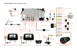
1
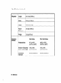
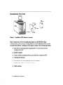
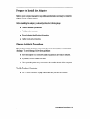
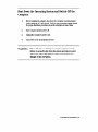
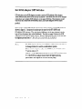
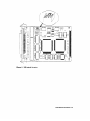
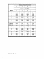
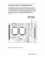
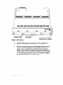
III’ A2969NA:36M
HP-HSC FastlWide
Diffkrentid
SCSI Adapt,ers
Installation and Service
0 Hewlett-Packard
Company,
1997. All rights reserved.
Hewlett-Packard Company makes no warranty of any kind with regard to this material, including, but not limited to, the
implied warranties of merchantability and fitness for a particular purpose. Hewlett-Packard shall not be liable for errors
contained herein or for incidental or consequential damages in connection with the furnishing, performance, or use of
this material.
This document contains proprietary information, which is protected by copyright. No part of this document may be
photocopied, reproduced, or translated into another language without the prior written consent of Hewlett-Packard.
The information contained in this document is subject to change without notice.
print
History
Edition 1, February 1995
Edition 2, March 1997
Safety Considerations
The product and related documentation must be reviewed for familiarization with safety markings and inshuctions
before installation and operation.
Safety
Symbols
manual
symbol. If the product is marked with this symbol, refer to the product
manuals to protect the product against damage.
Instruction
I
A ,
WARNING
CAUTION
A WARNING denotes a hazard that can cause personal ir\iury.
A CAUTION denotes a hazard that can damage quipment
Do not proceed beyond a WARNING or CAUTION notice until you have understood the
hazardous conditions and have taken appropriate steps.
Grounding
The computer in which this product is installed is a safety class I product and has a protective earthing terminal.
There must be an uninterruptible safety earth ground from the main power source to the product’s input wiring
terminals, power cord, or supplied power cord set. Whenever it is likely that the protection has been impaired,
disconnect the power cord until the ground has been restored.
Servleing
Any servicing, adjustment, maintenance, or repair must be performed only by authorized service-trained
personnel.
If you have any questions about the warranty for your product, contact your dealer or your local Hewlett-Packard
sales representative.
2
Regulatory
Statements
FCC Statement (For U.S.A. Only)
Federal Communications Commission Radio Frequency Interference Statement
Warning: This equipment generates, uses, and can radiate radio frequency energy. If it is not
installed and used in accordance with the instruction manual, it may cause interference to radio
communications. It has been tested and found to comply with the limits for a Class A
computing device pursuant to Part 15 of FCC Rules, which are designed to provide reasonable
protection against interference when operated in a commercial environment. Operation of this
equipment in a residential area is likely to cause interference, in which case the user at his own
expense will be required to take whatever measures may be required to correct the interference.
If this equipment causes interference to radio reception (which can be determined by turning
the equipment off and on) try these measures: Reorient the receiving antenna. Relocate the
computer with respect to the receiver. Move the equipment away from the receiver. Plug the
computer and receiver into different branch circuits. Consult your dealer or an experienced
technician for additional suggestions.
VCCI Class 1 (For Japan Only)
Hewlett-Packard
Company
Enterprise
Storage Solutions
Division,
Roseville,
CA 96747-6588
About
This Book
This book is the installation and service manual for the HP A2969AEIP A3644A HP-HSC
agh-Speed System Gonnect) Fast/Wide Differential SCSI Adapters. The HP A2969A adapter
connects an HP 9000 Series Kxxx computer (using the HP-UX operating system release 10.0 or
later) to SCSI devices, and the HP A3644A adapter connects an HP 9000 Series T6xx computer
(using the HP-UX operating system release 10.3or later) to SCSI devices.
This book contains reference information, installation procedures, and service information.
The reference information provides a description and technical specifications for the adapters.
The installation procedures contain the steps necessary to install the adapter in your computer.
The service information defines the steps and procedures to follow if you experience trouble
with the adapter. The information includes troubleshooting tools, removal and replacement
instructions, and reshipment guidelines.
4
Table of Contents
1
Reference
Description .................................
Product Contents ...........................
spectica.tions ................................
2
Installation
.8
.8
.
Procedures
12
InstaUation Overview ............................
13
.......................
PreparetoInstalltheAdapter
13
Observe Antistatic Precautions ....................
.13
Verify Product Contents .......................
14
Record Adapter Information ......................
14
Gather Tools and Accessories .....................
Shut Down the Operating System and Switch Off the Computer. ... 15
16
Set SCSI Adapter DIP Switches ......................
19
If Necessary, Remove the Termination Resistors ............
..2 0
...........................
InstalltheAdapter
Install the HP A2969A SCSI Adapter in an HP 9000 Series Kwr . . 21
Install the HP A3644A SCSI Adapter in an HP 9000 Series T6xx . . 24
29
Connect Cable and Peripheral Devices ..................
.29
SCSI Cable Connection ........................
.31
Peripheral Device Connections ...................
.32
..........................
TerminatetheSCSIBus
Switch Power on to Peripherals, then to the
Computer ................................
Configure the Operating System and the Adapter ...........
Verify Operation ..............................
3
Service
...33
.34
.34
Information
Field Replaceable Units ..........................
Exchange Assembly. .........................
Troubleshooting Tools ...........................
Term Power LED ............................
...................
ReplacingtheTermPowerFkse
Off-Line Diagnostics .........................
MAPPER...............................4
IOTEST................................4
RemovaVReplacement Instructions ...................
Removal/Replacement of the Adapter ...............
Reshipment Guidelines ..........................
.36
.36
37
.37
.33
.40
0
1
.42
-42
.43
Glossary ....................................................................................................................... 45
Index ...............................................................................................................,............. 49
1
Reference
Contents
Description.. ...................................................
.8
specifications.. ................................................
9
Reference
7
Description
The Hewlet&Packard &h-Speed astern Connect (HP-HSC) Fast/Wide Differential SCSI
Adapter provides the hardware needed to connect an HP 9ooo Series computer to E-bit
SCSI devices.
Product
Contents
Your product will consist of one set of the following items, depending on whether the
product is an A2969A SCSI adapter or an A3644A SCSI adapter.
Item
A2969A
HP-HSC Fast/Wide Differential SCSI
A2969AX
A3644A
Adapter
SCSI Termhator
Product Number:
Al65862024
C2905A
A165862024
C2905A
2.5meter cable (16bit high-density)
Al65862020
A165862020
Grounding wrist strap
9300-1408
93OcL1408
Installation
A296940002
A2969-90002
8 Reference
and Service Manual
Specifications
General
Features
supported
SyStemS
j Standards
Electrical
HP A2969A
HP A3644
HP 9000 Series K&x
computers using HP-UX
10.0 or later
HP 9000 Series T6xx
computer using HP-UX
10.3 or later
Complies with ANSI X3T9.2 SCSI specifications
Performance
20-Mbytekc
Connector
68-pin high-density P-type
Power
Consumptior
6.75 W @ 5.OV
0.75 w @ 3.3v
peak synchronous transfer rate
Reference
9
Specifications
Physical
(continued)
Length
15.11 cm (5.95 in.)
Width
8.76 cm (3.45 in.)
Height
2.54 cm (1.0 in.)
Board
Thickness
1.5 mm (0.06 in.)
Weight
114 g (4.02 02)
Operating
Non-Operating
Temperature
5°C to 40°C
(41*F to 104°F)
4o”c to 70°C
(-4OOFto 158°F’)
Relative Humidity
(non-condensing)
15%to 84E-G
at 40°C (104°F)
15%to 95%
at 65OC(149OF)
MWinUUtl
Altitude
4.6 km (15,000 ft)
4.6 km (15,000 ft)
Environmental
10 Reference
2
Installation
Procedures
Contents ..................................................................... ................ ............. Page
InstaIIation overview.. ............................................................................................
12
Prepare to install the adapter ...............................................................................
13
Shut down the operating system and switch off the computer ....................... 15
Set SCSI adapter DIP switches.. ...........................................................................
16
If necessary, remove the termination resistors.. ................................................19
InstaII the adapter.. .................................................................................................
20
InstalltheHPA2969AadapterinanHP9000SeriesKxxx..
.............................21
InstaIl the HP A3644A adapter in an HP 9000 Series T6xx.. .............................24
Connect cable and peripheral dev ices.. ..............................................................
29
Terminate the SCSI bus .........................................................................................
32
Switch power on to peripherals, then to the computer ....................................33
Configure the operating system and the adapter.. .............................................34
Verily operation ......................................................................................................
34
InstallationProcedures
11
Installation
Overview
0
Figure
1. Installing
a SCSI adapter,
. .
overview
F’lgure 1 presents an overview of installing the adapter in an HP 9000 Series Xxx
computer system. The procedure is slightly different for the HF’ 9000 Series T6xx and will
be noted where different. Installing the SCSI adapter consists of the following major steps:
Shut down the operating system using shutdown -h 0 (not reboot) and turn
computer power off.
Install the adapter
Connect cables and peripheral devices, and check for no duplicate ADDX.
Terminate the SCSI bus.
Switch power on to the peripherals, then to the computer.
Configure the software to include the adapter.
Verify operation.
12 hstdlation
Procedures
Prepare to Install the Adapter
Refer to your computer manuals for any additional information necessary to install the
adapter in your computer system.
Before installing the adapter, you should perform the following steps:
n
Observe antistatic precautions.
n
Verify product contents.
n
Record adapter identification information.
n
Gather tools and accessories.
Observe
Antistatic
Precautions
This product contains electronic components that can be damaged by an electrostatic
discharge. To avoid damage, follow these guidelines:
n
Store the adapter in a conductive plastic bag until you are ready to install it.
m
If possible, work in a static-free area.
a Use a grounding wrist strap connected to the metallic chassis of the computer.
Verify
n
Product
Contents
See “Product Contents” on page 8 and make sure you have all contents.
InstaUationProcedures
13
Record
Adapter
Information
Record the part number and date code of the adapter for future reference. If your
adapter requires service in the future, the part number and date code will be needed by
HP service personnel. This information is provided on stickers affixed to the adapter.
See the example below (note that your information might differ from the example).
B-3XXX
3XXX Made in USA
I
Gather
I
Tools and Accessories
The only tools required when installing the SCSI adapter are a #lO Torx driver or a
small flabblade screwdriver, and a grounding wrist strap.
14
Installation Rocedures
Shut Down the Operating System and Switch Off the
Computer
1.
Before installing the adapter, shut down the computer operating system
(using shutdown -h 0, not reboot). Refer to your computer system manual
for proper shutdown procedures to avoid corruption or loss of data.
2.
Turn computer system power off.
3.
Unplug the computer’s power cord.
4.
Turn power off on all peripheral devices.
WARNING
Unless otherwise noted in your computer system manuals,
failure to properly shut down the system and remove power
may create a personal hazard, or may result in hardware
damage or data corruption.
lnstallstion
Procedures
16
Set SCSI Adapter DIP Switches
DIP switches on the SCSI adapter are used to set the SCSI address of the adapter.
These switches are preset at the factory at address 7 and should not need to be changed
unless there are multiple SCSI initiators on the same SCSI bus. This situation would
only occur in a multi-host environment, that is, if you are using the ServiceGuard
product.
If you need to set the DIP switches, the location of the switches on the SCSI adapter is
shown in figure 2. Component locations are the same for the HP A2969A and
HP A3644A SCSI adapters. The only physical difference in the two adapters is in the
type of front faceplate (also called bulkhead). The table on page 18 shows the SCSI
addresses for the various switch settings. For bus arbitration the order of priority with
the highest priority first is: 7,6,5,4,3,2,1,0, 15, 14, 13, 12, 11, 10,9,8.
Note
16 Installation
The SCSI adapter is factory set to SCSI bus address ‘7’ and should not
be changed unless it is used in a multi-initiator system.
If there are two adapters on the same SCSI bus, one should be set to
‘7’ and the other to ‘6’.
Address ‘7’ is the highest priority address on the SCSI bus followed by
‘6’. If the SCSI host adapter doesn’t have the highest priority,
performance wdl degrade or the SCSI bus may hang.
Rocedures
u
n
l?
Figure
L
2. DIP switch
location
InstsUation
Procedures
17
Numbers
:I
Address
18 lxMallation
Procedures
on Printed-Circuit
Card
I
If Necessary, Remove the Termination
Resistors
If the SCSI Adapter is installed in the middle of a SCSI bus, that is, not at the end as
shown in figure 1 on page 12, the termination resistors on the SCSI Adapter should be
removed. (This would only occur in an HA solution with greater than two CPUs, or if a
V cable is used.) See figure 3 for the locations of the termination resistors (remember,
the component locations on the two adapters are identical except for the front
faceplate).
Terminatiin resistors
(Part number 1810-1418)
II -1
klldMLl
1234
RRAR
rll-l
OPEN
OPEN
Figure
3. Termination
resistor
r
locations
Installation
Procedures
19
Install the Adapter
For the HP 9000 Series Kxxx computer system, the HP AZ969A SCSI adapter can be
installed in a slot in either the core I/O or the HP-HSC expansion I/O.
For the HP 9000 Series T6xx computer system, the HP A3644A SCSI adapter is installed
in a slot in the HP-HSC I/O bus converter.
20 Instaua.tion
Procedures
Install
the HP A2969A
SCSI Adapter
in an HP 9000 Series Kxxx
To instaIl the HP A2969A SCSI adapter in an HP 9000 Series I&xx computer, perform
the following steps:
1.
Shut down the operating system and turn power off to the computer. (See
page 15.)
2.
Wear a grounding wrist strap that is connected to the core I/O or expansion
I/O bulkhead.
3.
Remove the core I/O or expansion VO from the computer. Refer to the
computer system manual for the necessary steps to remove the core I/O or
expansion I/O.
4.
Grasp the SCSI adapter by its edges or faceplate. Do not touch electronic
components or electrical traces. Recheck the DIP switches on the SCSI
adapter for the correct setting.
5.
If the SCSI adapter is to be installed in the core I/O, use the slot labeled
‘OPTIONAL I/O (J/8)*‘. If the SCSI adapter is to be installed in the
expansion I/O, select an empty slot on the expansion I/O. Seefigure 4 for
slot identifications.
InstallationProedures21
Slot cover screws
Figure
4. slot locations
Slot covers
/
Orange stripe indicating top
(matches strip on computer)
6.
Install the SCSI adapter into the slot in the core I/O or expansion I/O.
7.
Insert the mounting tabs (located on the SCSI adapter faceplate) into the
slots in the core I/O or expansion I/O bulkhead, then line up the SCSI
adapter connector with the receptacle on the core I/O or expansion I/O
adapter. Figure 5 shows the SCSI adapter beiig installed on the expansion
I/O. The procedure is the same for the core VO except that the adapter is
installed in the slot labeled ‘OPTIONAL I/O (X/8)‘.
22 Installation
Rocedures
Figure
5. Installing
the adapter
in the I/o bulkhead
8.
Press down on the rear of the SCSI adapter until its connector is fully
inserted into the receptacle on the core I/O or expansion I/O adapter.
9.
Secure the adapter by tightening the two retaining screws (Iocated on the
front of the core I/O or expansion YO bulkhead).
10.
If the SCSI adapter was installed in the expansion I/O, record the expansion
I/O slot number for future reference.
11.
Re-install the core I/O or expansion I/O. Refer to the computer system
manual for information on re-installing the core I/O or expansion I/O.
Installation
Procedures
23
Install
the HP A3644A
SCSI Adapter
in an HP 9000 Series T6xx
The HP A3644A SCSI adapter (see figure 6) is physically identical to the HP A2969A
adapter except for the front bulkhead, thus, the locations of the DIP switch and the
termination resistors are the same.
The HP A3644A adapter is installed in an HP-HSC I/O bus converter, which is then
instaIled in the HP 9000 Series T6xx computer. The HP-HSC YO bus converter is shown
in figure 7. Four SCSI adapters can be installed in one HP-HSC VO bus converter.
Bulkhead mounting screws
Figure
6. HP A3644A
24 Installation
SCSI adapter
Procedures
Figure
7. HP-H!3C I/O bus converter
To install the HP A3644A SCSI adapter in an HP 9000 Series T6xx computer, perform
the following steps:
1.
Shut down the operating system and turn power off to the computer. (See
page 15.)
2.
Wear a grounding wrist strap that is connected to the HP-HSC I/O bus
converter bulkhead.
3.
Remove the HP-I-NC J/O bus converter from the computer. Refer to the
computer system manual for instructions.
4.
Grasp the SCSI adapter by its edges or faceplate. Do not touch electronic
components or electrical traces. Recheck the DIP switches on the SCSI
adapter for the correct settings.
Installation
Procedures
26
Remove the cover blank from the slot where the SCSI adapter is to be
mounted. See figure 8. To remove the cover blank, remove the two screws
holding the blank in place. The screws are spring loaded. Apply slight
upward pressure to prevent the screw from separating from the spring.
5.
Figure
8. Removing
26 Instalhtion
a cover blank
Procedures
6.
Figure
Install the SCSI card in the HP-HSC converter by pressing the card against
the bulkhead of the HP-HSC converter. Seefigure 9.
9. Installing
the HP A3644A card
Instalition
Procedures
27
7.
Before you push the connector on the SCSI card into the mating connector
on the I-EHSC bus converter, turn the captive screws on the HP-HSC bus
converter until they engage the SCSI card, but do not tighten the screws.
8.
Align the connectors, then press them together securely.
9.
Tighten the HP-HSC bulkhead screws to secure the SCSI adapter to the
HP-HSC I/O bus converter.
10.
Re-install the HP-HSC I/O bus converter in the computer system. Refer to
the computer system manual for instructions on installing the HP-HSC bus
converter.
28 Installation Procedures
Connect Cable and Peripheral
Devices
With the adapter installed in the computer, you can now connect the adapter cable and
the peripheral devices.
SCSI Cable Connection
Attach the SCSI cable to the adapter as follows:
1.
Inspect the connector pins to be sure they are straight.
2.
Carefully plug the cable connector into the SCSI adapter receptacle on the
computer system. See figure 10. Note that figure 10 shows the cable being
attached to an HP 9000 Series I&xx computer; the procedure for the HP
9000 Series l%xx computer is very similar.
CAUTION
Do not bend any of the cable connector pins.
Insert connectors by pushing straight in
and remove them by pulling straight out.
Do not rock connector top to bottom or side to side.
3.
Secure the connector with the attached thumbscrews.
4.
Secure the other end of the cable to a SCSI device.
Installation
Procedures
29
Figure
10. Connecting
30 InstaUationAocedmes
cables to the computer
Peripheral
Device Connections
When connecting SCSI devices, follow these guidelines:
Verify the host computer system is shut down. There should be no data
transfer activity on the SCSI bus.
Verify power is off to the peripheral device before connecting it to the SCSI
bus.
Check whether your devices contain internal SCSI bus terminators or require
special terminates. If so, refer to your device manuals for instructions on
how to prevent excessive or improper SCSI bus termination.
Set switches or jumpers on your device(s) as appropriate. Be sure each SCSI
device has a unique SCSI address. Remember the default address of the SCSI
adapter is 7.
If a device other than the adapter also supplies termination power, its optimal
location is at the end of the SCSI bus. However, devices that supply
termination power can be distributed anywhere along the bus.
Use HP-supplied cables.
Do not exceed the maximum SCSI bus length of 25 meters. This includes any
bus Iengths internal to peripheral devices. Refer to peripheral device or
system configuration manuals for internal device lengths.
Do not exceed the maximum number of devices supported. (The differential
SCSI bus can support 16 devices including the SCSI adapter; however, only 7
SCSI Cascade Arrays can be connected. Note that SCSI Cascade Arrays are
only supported on HSC for the HP 9000 Series 700 on NIO adapters.)
installation
Procedures
31
Terminate
the SCSI Bus
Unless the SCSI bus is properly terminated, the bus will not operate properly.
Terminators provide matching impedance on SCSI bus signal lines.
This product includes an external SCSI bus terminator to terminate the peripheral end
of a differential SCSI bus. The terminator consists of a 68-pin, high density male
connector with thumb screws.
Install the external terminator on the end of the SCSI bus (opposite the SCSI host
adapter). If an intermediate device has internal terminations installed, remove them
before attaching the external terminator.
CATJTION
Only the two ends of a SCSI bus should be terminated.
Excessive or improper termination may overload the adapter’s
termination power circuitry. Refer to device manuals for their
proper operation on the SCSI bus.
See figure 1 on page 12 for an example of SCSI bus termination.
32 Instcrllation
Rocedures
Switch Power on to Peripherals,
Computer
then to the
Before applying power to your system, follow these guidelines:
1.
Verify all cables are connected and securely fastened.
2.
Switch power on to your peripheral devices and wait for them to become
ready before you switch power on to your computer.
3.
Switch power on for your computer.
When the computer’s power is switched on, power is supplied to the SCSI adapter. The
SCSI adapter supplies termination power to the SCSI bus. Some peripheral devices
may also supply SCSI bus termination power.
CAUTION
Do not switch power on or off on any device connected to an
active SCSI bus. Similarly, devices should not be added to, or
removed from, an active SCSI bus. Failure to comply may
result in data corruption or loss, or damage to hardware.
installation
Procedures
33
Configure the Operating System and the Adapter
The HP-HSC Fast/Wide Differential SCSI adapter should au&xonfigure into supported
HP-UX systems. When the operating system reboots it will determine your adapter has
been installed and will install the correct software device files necessary for the
operating system to communicate with peripherals connected to the adapter.
Verm Operation
The only indication of proper operation on the adapter is the green TERM POWER LED
located on the adapter bulkhead. If this LED is on, it indicates the adapter is supplying
termination power to the SCSI bus.
If the TERM POWER LED is off, refer to the Service Information chapter of this manual
for help.
If the TERM POWER LED is on but the SCSI device connected to the adapter does not
operate properly and you suspect the adapter is malfunctioning, refer to the Service
Information chapter of this manual for help.
34 InstallationRocedures
3
Service
Information
contents..................................................Page
Field replaceable units.. ................................
.36
Troubleshooting tools.. ..................................
37
Removal/replacement instructions .............42
Reshipment guidelines ...................................
43
Service Information 36
Field Replaceable Units
F’ield replaceable units (FRUs) are assemblies or components that are authorized for field
replacement.
Replaceable FlXJs on the HSC Fast/Wide Differential SCSI adapter:
Description
Part Number
125V, 2A, LF Fuse
2110-0517
Termination resistors
(Removed only during the
installation procedure
in a multi-jnitiator
situation.)
1810-1418
Exchange
Assembly
The adapter may be replaced under the HP exchange program. Adapter part numbers are
listed below:
HP A2969A
HPA3644A
New adapter
A2969Ax
Ai3644Ax
Exchange adapter
AZ96969001
A332969109
36 Service Information
Troubleshooting
Tools
Troubleshooting tools are used to identify faulty adapters. For this product, the following
tools are available:
n
Term Power LED
n
Off-line diagnostics
Term Power LED
The termination power (Term Power) LED is green and indicates the adapter is supplying
termination power to the SCSI bus. During proper operation, this LED is on.
If the Term Power LED is off, this adapter is not supplying power to the SCSI bus.
Possible faults include:
n
Blown
fuse
m Faulty adapter
n
Faulty SCSI device
n
Faulty cable connection (bent pins or improper seating of cable connector)
service Infol-mation 37
Replacing
the Term Power
Fuse
To remove and replace the Term Power fuse (F3), proceed as follows:
1. Remove the SCSI adapter from the computer. See the removal instructions on
page 42.
2. Pull the fuse out of its socket. The location of the fuse on the SCSI adapter is
shown in figure 11. Visually verify if the fuse is open, or by using a continuity
tester.
Fuse F3
Figure
11. Term power fuse location
38 service information
3. To install the replacement fuse, carefully align the two contact pins with the
socket holes. Then press the fuse in (refer to figure 12). The fuse has no
polarity, so the pins can go into either socket hole.
SCSI Adapter
Contact Pins
Fuse
part number 21100517
Fuse Socket
Figure
12. Installing
a replacement
fuse
selvice Information
39
Off-Line
Diagnostics
The Off-Line Diagnostic Environment (ODE) is used to test to the I/O adapter level in the
computer system. IOTESl’ and MAPPER are modules of ODE that check the functionality
of the I/O modules in the computer system. ODE is run from the Initial System Loader
(EL) on the system console.
MAPPER
ODE> mapper
MAPPER>run
The MAPPER utility provides the following hardware information:
1.
2.
3.
4.
5.
6.
Path#
Type ID (Architecture Module)
Hardware Version
Hardware and F’irmware Versions
SCSI bus address of host adapter
Names and addresses of devices on the SCSI bus.
MAPPER automatically resets the SCSI bus.
40 selviceIllfomlation
IOTEST
ODE> iotest
IOTEST> run
The IOTEWs strategy is to systematically check the basic functionality of I/O modules in
the system. This is accomplished by either making a PDC-IODC call to invoke selftest, or
by running a test within the diagnostic. IOTESl’ doesn’t test the functionality of devices.
IOTESl’ is currently divided into 23 sections. Each section performs basic tests on a
particular module.
Note
No on-line diagnostics are available for the HP-HSC SCSI adapter.
serviceInformation
Removal/Replacement
Instructions
Removal of the SCSI adapter is the opposite of installation. Follow the instructions
presented here and refer to the installation procedures on page 20.
The adapter contains electronic components that can be damaged
by static electricity. To avoid damage, follow these guidelines:
CAUTION
Store adapters in their conductive plastic bags.
H If possible, work in a static-free area.
n
n
Handle adaptersonly by the edges. Do not touch electronic components
or electrical traces. Use a grounding wrist strap connected to the
metallic chassisof the host computer.
Removal/Replacement
of the Adapter
For adapter removal, follow the procedures below:
1. Before removing the adapter, ensure the operating system is shut down and
power to the computer and all devices is switched off and disconnected.
Consult your computer documentation for proper shutdown procedures to
avoid file corruption or loss of data.
2. Disconnect all cabling from the adapter.
3. Refer to the installation procedures on page 20.
To install a replacement adapter, follow the procedures described on page 20.
42 Service Information
Reshipment Guidelines
If any item of the product is to be returned to Hewlett-Packard for any reason, contact
your HP Sales and Support Office to coordinate the return.
When returning the item, attach a tag that identifies the owner and indicates the reason for
shipment. Include the part number of the item and date code.
Pack the item in the original factory packaging material if available, or a suitable
substitute. Provide antistatic protection to applicable components or assemblies.
service Information 43
44 service
Information
Glossary
adapter
A computer interface card and circuitry that provides the physical connection and data
translation between the host computer’s I/O bus and external devices or networks.
adapter
slot
The location where adapters attach to the backplane. See Slot.
backplane
For an I/O bus, the computer’s circuitry and connectors to which adapter cards connect.
HP-HSC
HewlettiPackard High-Speed System Connect. Name given to one of the computer system
I/O buses.
ISL
Initial System Loader. ISL implements the operating system independent portion of the
bootstrap process. ISL is loaded and executed after self-test and initialization have
completed successfully. When executed, it loads HP-UX or other operating environments
(e.g., ODE “Ofiline Diagnostic Environment”) as specified.
LED
See light emitting diode.
Glossary 46
light
emltting
diode
A smaUlight emitting device used to provide status information.
Mbitdsec
Megabits per second (l,OOO,OOO
bits per second).
medium,
media
The tmnsmission connection between nodes. Most current I&k use cables (fiberoptic or
copper), although radio and other broadcast media are possible.
ODE
Off-lie Diagnostic EJnvironment. A distributed diagnostic execution environment
launched from ISL.
SCSI
Small Computer System Interface, often pronounced “skuzzy”.
SCSI address
The binary representation of the unique address (0 to 15) assigned to each device and
adapter on the SCSI bus. For bus arbitration the order of priority with highest first is: 7,6,
5,4,3,2,1,0, 15, 14, 13, 12, 11, 10,9,8. SCSI addresses are typicahy assigned during
installation. The SCSI adapter is typically assigned address “7”.
46 Glossary
SCSI bus
The collection of SCSI signal lines that interconnect SCSI devices and adapters.
SCSI ID
SCSI identification. The bit-significant representation of the SCSI address referring to one
of the bus signal lines DB (7 - 0,15 - 8). See also SCSI address.
slot
The physical place in the back of the computer where an adapter plugs in. Each slot has a
number, which in its hexidecimal form is used as part of the hardware address of the
device. See adapter slot
terminator
A device that contains a resistive network to terminate the peripheral end of a SCSI bus.
The peripheral end of the SCSI bus may not need a terminator if the last peripheral device
on the bus already contains SCSI termination resistors.
termination
To complete the bus circuitry at each end of a SCSI bus, the electrical lines (at each end
only) must be terminated with a resistive network. The HP-HSC Fast/Wide Differential
SCSI adapter contains termination resistor packs on the adapter and must be located at
one end of the SCSI bus. See also terminator.
Glossary 47
Index
A
A2969AX, 8
A3644Ax, 8
adapter information, 14
antistatic precautions, 13
B
bus arbitration, 16
C
cable connection, 29
component locations, 16
connect cable and peripheral devices,
29
connect peripheral devices, 29
connector type, 9
core I/O, 2 1
cover blank, 26
D
description, 8
DIP switches, 16
E
electrical specifications, 9
environmental specifications, 10
exchange assembly, 36
expansion YO, 2 1
F
field replaceable units, 36
front faceplate, 16
FRUs, 36
G
general features, 9
H
HP 9000 Series Kxxx computers, 9
HP 9000 Series T6xx computers, 9
HP-HSC expansion I/O, 20
HP-HSC I/O bus converter, 24
I
install the adapter, 20
install the HP A2969A SCSI adapter, 2 1
install the HP A3644A SCSI adapter, 24
Index
49
installation
antistatic precautions, 13
cable connection, 29
configuring the SCSI adapter into
the operating system, 34
connecting cables and peripheral
devices, 29
installing the HP A2969A SCSI
adapter, 2 1
installing the HP A3644A SCSI
adapter, 24
overview, 12
peripheral device connections, 3 1
procedures, 11
recording adapter information, 14
removing termination resistors, 19
removing the core I/O or expansion
L/o, 21
removing the HP-HSC I/O bus converter, 25
setting SCSI adapter DIP switches,
16
shutting down the operating system, 1.5
switching computer power on, 33
switching power off to the computer, 15
switching power on to peripherals,
33
terminating the SCSI bus, 32
tools and accessories required, 14
verify product contents, 13
verifying proper operation of the
SCSI adapter, 34
installation procedures, 11
IOTEST, 41
50 Index
M
MAPPER, 40
maximum number of devices supported, 31
maximum SCSI bus length, 3 1
0
Off-Line Diagnostic Environment
(ODE), 40
off-line diagnostics, 37
operating system, configuring the SCSI
adapter into, 34
overview of installing the adapter, 12
P
performance, 9
peripheral device connections, 3 1
physical specifications, 10
power consumption, 9
product contents, 8
R
reference, 7
removaUreplacement instructions, 42
remove the cover blank, 26
reshipment guidelines, 43
S
SCSI adapter DIP switches, 16
SCSI bus highest priority, 16
SCSI bus, terminating, 32
SCSI Cascade Arrays, 3 1
service information, 35
shut down the operating system, 15
slot locations, 21, 25
specifications, 9
standards, 9
supported systems, 9
switch computer power on, 33
switch power off to the computer, 15
switch power on to peripherals, 33
T
Term Power fuse, location, 3 8
Term Power fuse, replacing, 38
TERM POWER LED, 34
terminate the SCSI bus, 32
termination power (Term Power) LED,
37
termination resistors, 19
tools and accessories, 14
troubleshooting tools, 3 7
V
verify proper operation, 34
Index
61
62 Index
Reader Comment Sheet
Fast/Wide Differential
SCSI Adapter Installation
and Service
We welcome your evaluation of this manual. Your comments and suggestions will help us improve our
publications. Remove this page, mail or FAX to 9167852875. Use and attach additional pages if necessary.
Disagree
NC
&me
The manual is well organized.
The information is technically accurate.
Information is easy to find.
Stepby-step procedures are easy to perform
There are enough examples and pictures.
The examples and pictures were useful.
0
0
0
0
0
0
0000
0
0000
0
0000
0
0000
0
0000
0
0000
0
Comments:
Name:
Date:
Title:
Company
Address
City & State:
zip:
countzy
Phone:
Hewlett-Packard has the right to use submitted suggestions without obligation, with all such ideas becoming proper@
of Hewlett-Pa&&.
-Check here if you would like a reply
A2969-9ooo2 Eo397
IllIII
NECESSARY
-I
I
BUSINESS REPLY MAIL
FLRsrcLAssPERMlT NO. 256 ROSFXILLE. CA
POSTAGE WILL BE PAID BY ADDRESSEE
-I
-1
I
-I
-1
-/
Attention: Learning Products (MS5668)
Hewlett-Packard
Company
Enterprise
Storage Solutions
8000 Foothills
Boulevard
Roseville, CA 95747-9987
Division
-r
-1
-;
-I
-I
I
III IIII II II IIll II III IIIII III III III II III II IIll III I II I
I
I
Fold Here
I
Tape
Please do not staple
Tape
I
HEWLETT
PACKARD
Manual Part Number
A2969-90001
E0397
0 Copyright 1997
Hewlett-Packard Company
Printed in 1J.S.A.
A2969-96002
III
lllll
Ill11111
lllll
llllll
II1111
lllll
lllll
lllllll