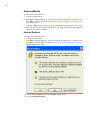
1
HP 24-Port 4x Fabric Copper Switch
Chassis Manager User Guide
March 2005 (Second Edition)
Part Number 377707-002
© Copyright 2005 Hewlett-Packard Development Company, L.P.
Confidential computer software. Valid license from HP required for possession, use or copying. Consistent with
FAR 12.211 and 12.212, Commercial Computer Software, Computer Software Documentation, and Technical
Data for Commercial Items are licensed to the U.S. Government under vendor’s standard commercial license.
The information contained herein is subject to change without notice. The only warranties for HP products and
services are set forth in the express warranty statements accompanying such products and services. Nothing
herein should be construed as constituting an additional warranty. HP shall not be liable for technical or editorial
errors or omissions contained herein.
Microsoft®, MS Windows®, Windows®, and Windows NT® are U.S. registered marks of Microsoft Corporation.
HP 24-Port 4x Fabric Copper Switch Chassis Manager User Guide
March 2005 (Second Edition)
Part Number 377707-002
i
Contents
Preface.......................................................... vii
Intended Audience .................................................................................................................................... vii
Typographical Conventions ...................................................................................................................... vii
Contact Information ................................................................................................................................. viii
1: About Chassis Manager............................. 1
Introduction..................................................................................................................................................1
Anatomy of Chassis Manager......................................................................................................................1
System Frame ................................................................................................................................. 1
Tree Frame ...................................................................................................................................... 2
View Frame..................................................................................................................................... 6
Browser Requirements.................................................................................................................................7
Platform Requirements ................................................................................................................................7
2: Getting Started ........................................... 9
Prepare Your Device....................................................................................................................................9
Launch Chassis Manager ...........................................................................................................................11
Launch Chassis Manager without SSL ......................................................................................... 11
Launch Chassis Manager with SSL .............................................................................................. 11
Avoid Error Messages .................................................................................................................. 13
Log Out of Chassis Manager ........................................................................................................ 14
Navigate Chassis Manager.........................................................................................................................14
Moving Backward......................................................................................................................... 15
Refreshing Views.......................................................................................................................... 15
Understand Access Privileges....................................................................................................................15
ii
View Device Status....................................................................................................................................15
3: Chassis Icon Tasks .................................. 17
View Cards on a Chassis ...........................................................................................................................17
View Card Properties.................................................................................................................... 19
View Card Inventory .................................................................................................................... 21
Configure Administrative Status of a Card................................................................................... 22
View Internal Gateway Ports .....................................................................................................................22
View Physical Ports on a Chassis ..............................................................................................................23
View Port Properties ..................................................................................................................... 23
View Port Bridging Properties...................................................................................................... 26
View Port Statistics....................................................................................................................... 26
Configure Ports ..........................................................................................................................................28
Configure a Port Name ................................................................................................................. 28
Enable or Disable a Port ............................................................................................................... 28
Configure Auto-Negotiation on a Port.......................................................................................... 28
Configure Port Speed.................................................................................................................... 28
View Power Supply Status ........................................................................................................................29
View Fan Status .........................................................................................................................................29
View Temperature Sensor Status...............................................................................................................30
View Backplane Information.....................................................................................................................30
View Management Ports on a Chassis.......................................................................................................31
4: Maintenance Icon Tasks .......................... 33
Configure Basic System Information ........................................................................................................33
View System Information ............................................................................................................. 34
Name Your InfiniBand Switch ..................................................................................................... 34
Define Device Location ................................................................................................................ 34
Define Technical Support Resource ............................................................................................. 34
Configure Date and Time Properties .........................................................................................................35
Configure Date and Time ............................................................................................................. 35
Assign NTP Servers...................................................................................................................... 35
View Files in the File System ....................................................................................................................35
Delete Files in the File System ..................................................................................................... 36
Install Software Images..............................................................................................................................36
Import Configuration Files and Image Files with FTP..............................................................................36
Export Configuration Files and Log Files with FTP .................................................................................37
Customize the Boot Configuration ............................................................................................................37
Back Up Running Configuration File ........................................................................................................37
Save Configuration File .............................................................................................................................38
Reboot ........................................................................................................................................................38
Configure Basic Services...........................................................................................................................38
Assign a DNS Server .................................................................................................................... 38
Enable or Disable the FTP Access................................................................................................ 38
Enable or Disable the Telnet Access ............................................................................................ 39
iii
Assign a SYSLOG Server............................................................................................................. 39
Assign an Authentication Method ................................................................................................ 39
Configure HTTP and HTTPS ....................................................................................................... 39
View RADIUS Servers ..............................................................................................................................40
View and Configure RADIUS Server Properties ......................................................................... 40
Add RADIUS Servers................................................................................................................... 41
Delete RADIUS Servers ............................................................................................................... 42
View Authentication Failures ....................................................................................................................42
View Diagnostic Test Results....................................................................................................................42
View POST Test Results .............................................................................................................. 42
View FRU Errors .......................................................................................................................... 43
5: InfiniBand Icon Tasks............................... 45
View Subnet Managers ..............................................................................................................................45
View Subnet Manager Properties ................................................................................................. 46
Add a Subnet Manager ................................................................................................................. 46
Delete a Subnet Manager .............................................................................................................. 47
Configure Subnet Manager Properties.......................................................................................... 47
View InfiniBand Services ..........................................................................................................................47
View InfiniBand Service Properties ............................................................................................. 47
View InfiniBand Nodes .............................................................................................................................48
View Node Properties ................................................................................................................... 48
View Node Ports ........................................................................................................................... 50
View Node Neighbors .................................................................................................................. 51
View InfiniBand Ports ...............................................................................................................................51
View InfiniBand Port Properties................................................................................................... 51
View Neighboring IB Devices...................................................................................................................56
View IB Neighbor Properties ....................................................................................................... 56
View IOUs .................................................................................................................................................57
View IOCs .................................................................................................................................................57
View IOC Properties..................................................................................................................... 58
View IOC Services ....................................................................................................................................59
View Properties of IOC Services.................................................................................................. 59
6: Ethernet Icon Tasks ................................. 61
View Bridge Groups ..................................................................................................................................61
View Bridge Group Properties ..................................................................................................... 62
Add Bridge Groups ....................................................................................................................... 62
Configure Bridge Groups.............................................................................................................. 63
Delete Bridge Groups ................................................................................................................... 63
View Bridge Subnets .................................................................................................................................64
Add Bridge Subnet........................................................................................................................ 64
Delete Bridge Subnet .................................................................................................................... 64
View Bridge Forwarding ...........................................................................................................................64
Add Bridge Forwarding ................................................................................................................ 65
iv
Delete Bridge Forwarding ............................................................................................................ 65
View Redundancy Groups .........................................................................................................................65
View Trunk Groups ...................................................................................................................................66
Add a Trunk Group....................................................................................................................... 67
View Trunk Group Properties....................................................................................................... 67
Configure a Trunk Group ............................................................................................................. 69
Delete a Trunk Group ................................................................................................................... 69
7: Fibre Channel Icon Tasks ........................ 71
Configure Global ITL Attributes ...............................................................................................................71
View SRP Hosts (Initiators) ......................................................................................................................72
View SRP Host (Initiator) Properties ........................................................................................... 73
View SRP Host (Initiator) World-Wide Port Names.................................................................... 73
View IT Policies of the Host......................................................................................................... 74
View ITL Policies of the Host ...................................................................................................... 74
Add SRP Host ............................................................................................................................... 74
Delete SRP Host ........................................................................................................................... 75
Configure SRP Host (Initiator) Properties.................................................................................... 75
View Fibre Channel Targets ......................................................................................................................75
View Fibre Channel Target Properties ......................................................................................... 76
Configure Fibre Channel Target Properties.................................................................................. 76
View IT Policies of the Target...................................................................................................... 77
View ITL Policies of the Target ................................................................................................... 77
View Fibre Channel LUNs ........................................................................................................................77
View Fibre Channel LUN Properties............................................................................................ 78
Configure Fibre Channel LUN Properties .................................................................................... 78
View ITL Policies of the LUN ..................................................................................................... 79
View IT Policies ........................................................................................................................................79
View IT Properties........................................................................................................................ 79
View ITLs ..................................................................................................................................................80
View ITL Properties ..................................................................................................................... 80
View Global Statistics ...............................................................................................................................81
v
Preface
This document is a guide to the Chassis Manager Web-based graphical user interface (GUI) that runs on
your Server Switch. This document explains how to use Chassis Manager (CM) and provides the steps
that you need to perform to configure your Server Switch with the GUI.
Intended Audience
The intended audience is the administrator responsible for installing, configuring, and managing your
equipment. This administrator should have experience administering similar networking or storage
equipment.
Typographical Conventions
The following typographic conventions are used in this manual to provide visual clues as to the purpose
or application of specific text.
•
Bold text indicates a command or keyword, or text that appears in your display.
•
Italics indicate variables that you replace with an actual value.
•
Square brackets ([,]) indicate an optional argument that you choose to include or exclude when you
enter a command.
•
Pipe character (|) indicates an “or” choice. For example, “a | b” indicates “a or b.”
•
Ellipses (…) indicate truncated text. You will see these in long examples depicting terminal output
that is too long to be shown in its entirety.
NOTE: Indicates an important point or aspect that you need to consider before continuing.
vi
Contact Information
Table 2-1: Customer Contact Information
For the name of your nearest authorized
HP reseller:
In the United States, call 1-800-345-1518.
In Canada, call 1-800-263-5868.
Outside the United States and Canada, refer to
www.hp.com.
For HP technical support
In the United States and Canada, call 1-800-HP-INVENT
(1-800-474-6836). This service is available 24 hours a day,
7 days a week. For continuous quality improvement, calls
may be recorded or monitored.
Outside the United States and Canada, refer to
www.hp.com.
1
1
About Chassis Manager
The following sections appear in this chapter:
•
“Introduction” on page 1
•
“Anatomy of Chassis Manager” on page 1
•
“Browser Requirements” on page 6
•
“Platform Requirements” on page 6
Introduction
The Chassis Manager (CM) runs directly on your switch to help you quickly and easily perform various
administration tasks. This chapter discusses the various components of the interface. CM runs on all
switches.
Anatomy of Chassis Manager
CM runs in a standard Web browser and displays information in standard HTML formats. The GUI
consists primarily of the following three frames:
•
System frame
•
Tree frame
•
View frame
System Frame
The System frame appears above the Tree and View frames and provides basic system information and
links to FRUs. Figure 1-1 displays an example of the CM System frame.
2
Figure 1-1: System Frame
•
Click the IP address in the IP Address field of the System frame to open a telnet window that
launches a CLI session to the switch.
•
Click the email address in the Support Contact field to send an email message to technical
support.
•
Click Help to open online help.
The System frame displays and updates the status of the cards, power supplies, and fans in your device.
Each number in the Cards, Power Supplies, and Fans fields identifies a field-replaceable unit (FRU)
in your device based on the slot number in which it resides. The color of the slot number indicates the
status of the FRU. Table 1-1 lists the colors in the display and explains what each color indicates.
Table 1-1: FRU Color Indicators
Color
Indication
green
Operational and administrative status of up.
gray
Administrative status of down.
red
Operational status of down.
Tree Frame
The Tree frame appears on the lower-left-hand side of the CM display and provides a navigation tree
that groups the functional branches of your device under icons. Figure 1-2 displays an example of the
Tree frame.
Figure 1-2: Tree Frame
NOTE: Figure 1-2 displays a Tree frame for a user with unrestricted access. Restricted users may see
fewer icons. For more information, refer to “Understanding Access Privileges” on page 15.
3
Table 1-2 lists and describes the icons in the Tree frame.
Table 1-2: Tree Frame Icons
Icon
Description
)
The Chassis icon lets you view and configure hardware in your switch. Access
this icon to view the status of all field replaceable units (FRUs) on your device.
Maintenance (
) The Maintenance icon contains branches that let you perform basic
administrative tasks on your switch. Access this icon to configure NTP servers,
assign a boot-config file, view the contents of the file system, etc.
Chassis (
InfiniBand (
Ethernet (
)
)
(select hardware
platforms only)
Fibre Channel
(
) (select
The InfiniBand® icon provides subnet manager (SM) and I/O details. You can
click the Subnet Manager branch of this icon to configure basic SM properties.
The Ethernet icon lets you view and configure many aspects of IP traffic on
your switch.
The Fibre Channel icon shows you SRP host and Fibre Channel (FC) storage
details and lets you configure global policies.
hardware platforms
only)
Help (
)
The Help icon takes you to on-line help and support resources.
Tree Frame Branches
1.
Click the plus-sign ( ) to expand an icon and display the branches that you can configure.
2.
Click a branch icon (
) to open the configuration options for that branch in the View frame.
Table 1-3 lists and describes the configurable branches under the Chassis icon.
Table 1-3: Chassis Icon Branches
Branch
Description
Cards
Click this branch to display and configure controller, switch, and gateway cards.
Ports
Click this branch to display and configure all external IB, Ethernet, and FC ports
on your device.
Power Supplies
(select hardware
platforms only)
Click this branch to view the status of the power supplies on your device.
Fans (select
hardware platforms
only)
Click this branch to view the status of the fans on your device.
Sensors
Click this branch to view the status and readings on the temperature sensors on
your device.
Backplane (select
hardware platforms
only)
Click this branch to view backplane details.
Management Ports Expand the Management Ports icon to display the following branches:
•
Serial—displays the Serial Console port configuration.
•
Ethernet—displays the Ethernet Management port configuration.
•
InfiniBand—displays the InfiniBand Management port configuration.
4
Table 1-4 lists and describes the configurable branches under the Maintenance icon.
Table 1-4: Maintenance Icon Branches
Branch
Description
System Information
Click this branch to view and configure the information that appears in the
System frame.
Time
Click this branch to configure the time and date on your switch and to assign
NTP servers to your device.
File Management
Click this branch to view, import, export, and install files in the file system on
your device.
Boot Configuration
Click this branch to select a configuration for your switch to use when it
boots.
Backup
Configuration
Click this branch to save your running configuration to a file.
Save Config
Click this branch to save the running configuration as the startup
configuration. When your switch reboots, it runs the updated configuration.
Reboot
Click this branch when you want to reload your switch.
Services
Expand the Services icon to display the following branches:
•
Diagnostics
General—displays the following system services and lets you configure
them:
•
DNS
•
FTP
•
telnet
•
syslog
•
RADIUS
•
HTTP
•
RADIUS Servers—displays the RADIUS server(s) that your device can
use to authenticate user logins and lets you configure attributes of the
server(s).
•
Authentication Failures—lists CLI, SNMP, and HTTP authentication
failures.
Click this branch to view switch diagnostic data.
Table 1-5 lists and describes the configurable branches under the InfiniBand icon.
Table 1-5: InfiniBand Icon Branches
Branch
Description
Subnet Managers
Click this branch to view and configure the SMs in your fabric.
Services
Click this branch to view the IB fabric services that have registered with
the SM.
Topology
Expand the Topology icon to display the following branches:
•
Nodes—click this branch to view the IB nodes in your IB fabric.
•
Ports—click this branch to view the IB ports in your IB fabric.
•
Neighbors—click this branch to display the interconnecting IB
nodes, and relevant ports, in your IB fabric.
5
Table 1-5: InfiniBand Icon Branches (Continued)
Branch
Description
Device Management
(select hardware platforms
only)
Expand the Device Management icon to display the following branches:
•
IOU—click this branch to view the I/O unit on your switch.
•
IOCs—click this branch to view the controller(s) on your device.
•
IOC Services—click this branch to view the IB features on your
device.
Table 1-6 lists and describes the configurable branches under the Ethernet icon.
Table 1-6: Ethernet Icon Branches
Branch
Description
Bridge Groups
Click this branch to view bridge groups on your switch.
Trunk Groups
Click this branch to view trunk groups on your switch.
Table 1-7 lists and describes the configurable branches under the InfiniBand icon.
Table 1-7: InfiniBand Icon Branches
Branch
Description
Global Policies
Click this branch to view and configure the default attributes of new IB-toFC connections.
SRP Hosts
Click this branch to view and configure SRP hosts that serve as initiators
for SAN fabrics.
Targets
Click this branch to view and configure FC targets that connect to your
switch through FC gateways.
Logical Units
Click this branch to view and configure FC Logical Units (LUNs) that
connect to your switch through FC gateways.
ITs
Click this branch to view and configure attributes of initiator-target
connections.
ITLs
Click this branch to view and configure attributes of initiator-target-LUN
connections.
Global Statistics
Click this branch to view IB-to-FC traffic statistics.
Table 1-8 lists and describes the configurable branches under the Help icon.
Table 1-8: Help Icon Branches
Branch
Description
Help Index
Click this branch to launch CM on-line help.
Support
Click this branch to open the HP support Web site.
View Frame
The View frame appears on the right-hand side of the interface. Input fields and device details appear in
this frame. The contents of the View frame vary based on the branch that you click in the Tree frame.
6
Figure 1-3 displays the table that appears in the View frame when you expand the Chassis icon and
click the Ports branch.
Figure 1-3: View Frame
Browser Requirements
CM supports the following browsers:
•
Microsoft® Internet Explorer version 6
•
Netscape Navigator version 6
•
Mozilla version 1.4
Platform Requirements
CM runs on the following platforms:
•
Windows®
7
•
Solaris
•
Linux
8
9
2
Getting Started
The following sections appear in this chapter:
•
“Preparing Your Device” on page 9
•
“Launching Chassis Manager” on page 11
•
“Navigating Chassis Manager” on page 14
•
“Understanding Access Privileges” on page 15
•
“Viewing Device Status” on page 15
Preparing Your Device
To launch CM on your Server Switch, you must:
•
Configure an IP address on the Ethernet management port.
•
Configure an IP gateway on the Ethernet management port.
•
Enable HTTP and/or HTTPS services.
NOTE: CM optionally supports Secure Sockets Layer (SSL) secure connections.
If your device meets these requirements, proceed to “Launching Chassis Manager” on page 11.
Otherwise, to prepare your device:
10
NOTE: Consult your network administrator for an IP address, subnet mask, and gateway address
before you begin this process.
1.
Use the Serial Console port to open a CLI session to your device, then log in as a user with
administrative access.
2.
Enter the enable command to enter Privileged Exec mode.
Example
Topspin-360> enable
Topspin-360#
3.
Enter the configure terminal command to enter Global Configuration mode.
Example
Topspin-360# configure terminal
Topspin-360(config)#
4.
Enter the interface mgmt-ethernet command to enter Ethernet Management Interface
Configuration submode.
Example
Topspin-360(config)# interface mgmt-ethernet
Topspin-360(config-if-mgmt-ethernet)#
5.
Enter the ip address command, then an address and subnet mask. Consult your network
administrator for an IP address. You will use this address in your Web browser to launch CM.
Example
Topspin-360(config-if-mgmt-ethernet)# ip address 10.3.102.66 255.255.0.0
6.
Enter the gateway command, then a default IP gateway. Consult your network administrator for a
gateway address.
Example
Topspin-360(config-if-mgmt-ethernet)# gateway 10.3.0.1
7.
Enter the no shutdown command to enable the Ethernet Management port.
Example
Topspin-360(config-if-mgmt-ethernet)# no shutdown
8.
Enter the exit command to return to Global Configuration mode
Example
Topspin-360(config-if-mgmt-ethernet)# exit
9.
Enable HTTP and/or HTTPS services.
a.
(Optional) Enter the ip http server command to enable HTTP services on your device to
permit unsecured access to your Server Switch.
Example
Topspin-360(config)# ip http server
11
b.
(Optional) Enter the ip http secure-server command to enable HTTPS services on your
device to permit SSL-secured access to your Server Switch.
Example
Topspin-360(config)# ip http secure-server
Launching Chassis Manager
CM without SSL requires no additional setup. CM with SSL requires additional steps based on
yourWeb browser.
Launching Chassis Manager without SSL
To launch CM:
1.
Launch your Web browser.
2.
Type the IP address of your Server Switch in the address field of your browser and press Enter.
(You configured the IP address in step 5 of “Preparing Your Device” on page 9.)
A login window opens. Figure 2-1 displays the login window.
Figure 2-1: CM Login Window
3.
Enter your Server Switch user name and password in the login window and click the OK button.
CM loads in your browser window.
Launching Chassis Manager with SSL
SSL setups vary by browser types. The following sections explain how to launch CM with particular
browsers.
12
Netscape/Mozilla
To launch a secure CM connection:
1.
Launch your Web browser.
2.
Type https:// and the IP address of your Server Switch in the address field of your browser and
press Enter. (You configured the IP address in step 5 of “Preparing Your Device” on page 9) A
login window opens.
3.
Click Yes or OK to close any browser messages. Mozilla dynamically manages your certificate.
4.
Enter your Server Switch user name and password in the login window and click the OK button.
CM loads in your browser window.
Internet Explorer
To launch a secure CM connection:
1.
Launch your Web browser.
2.
Type https:// and the IP address of your Server Switch in the address field of your browser and
press Enter. (You configured the IP address in step 5 of “Preparing Your Device” on page 9) A
Security Alert window opens.
3.
Click the View Certificate button. The Certificate window opens.
4.
Click the Certification Path tab.
13
5.
Click the root certificate in the tree.
Example
6.
Click the View Certificate button.
7.
Click the Install Certificate button.
8.
Click the Next button.
9.
Click the Place all certificates in the following store radio button.
10. Click the Browse button. The Select Certificate Store window opens.
11. Click Trusted Root Certification Authorities, then click OK.
12. Click the Next button, then click the Finish button.
Avoiding Error Messages
By default, SSL certificates map to the IP address of the Ethernet Management Port of a Server Switch.
If you enter one of the following, your browser displays an alert:
•
the system name of your host (that you configure with the hostname command)
•
the IP address of the InfiniBand Management Port of your Server Switch to launch CM.
14
The alert cautions you that the name on the certificate does not match the name of the site. This
hostname mismatch message reappears after you log in and the java applet begins to load. To avoid this
message entirely, configure your Server Switch to use the identifier that you enter in the browser to
verify certificates.
To configure the certificate name to use the system name:
1.
Telnet to your Server Switch and log in as a user with administrative privileges.
Example
Login: super
Password: xxxxx
2.
Enter the enable command to enter Privileged Exec mode.
Example
Topspin-270> enable
Topspin-270#
3.
Enter the configure terminal command to enter Global Configuration mode.
Example
Topspin-270# configure terminal
Topspin-270(config)#
4.
Enter the ip http command with the following to configure your certificates to use the system
name of your Server Switch:
•
the secure-cert-common-name keyword
•
the system name (hostname) of the Server Switch
Example
Topspin-270(config)# ip http secure-cert-common-name useSysName
Now, when you open CM with the system name of your Server Switch, error messages will not
repeatedly appear.
Logging Out of Chassis Manager
To log out of CM, close the Web browser window that displays the GUI. If you have multiple windows
open (such as the main CM window and a “properties” window), close all such windows.
Navigating Chassis Manager
The Tree frame of the Web-based interface provides a high-level map of CM. As you move from
display to display in CM, the View frame constantly reminds you where you are in the system.
When you click a branch in the Tree frame, the title of the display that appears in the View frame
matches the name of the branch. Directly below the display title appears a tiered locator that details the
level of the current display in relation to other elements of CM. For instance, when you click the Cards
branch of the Chassis icon, the following locator string appears:
A.B.C.D > Chassis > Cards
In this instance, A.B.C.D represents the IP address of your Server Switch. The tiered locator indicates
that your current display is the Cards display, which is a branch of the Chassis icon on the device with
an IP address of A.B.C.D.
15
When you further filter your display, the View frame indicates the new level of granularity. For
instance, if you view the ports on a particular gateway card instead of all ports on the device, a tiered
locator appears, followed by a filter indicator. If you view only external ports on an Ethernet gateway in
slot 4, the following identifiers appear:
A.B.C.D > Chassis > Ports
Filter : Card = 4
The second identifier indicates that the display shows only the ports on Card 4.
Moving Backward
Because no formal “move backward” function exists in CM, use one of the following options to return
to a previous display:
•
Click the Back button on your Web browser.
•
Right-click the View frame and select Back from the pop-up menu.
•
Navigate to the desired display with the Tree frame.
NOTE: When you use the Back button of your Web browser, your browser may not cache selections
that you made for a particular view. For instance, if you view the gateway ports of a card, then click a
branch in the Tree frame, your previous display may not appear correctly when you click the Back
button.
Refreshing Views
CM lets you update most displays to reflect changes that occurred since you opened the display. To
refresh your view, click the Refresh button in your display.
Understanding Access Privileges
The functionality available to you from CM varies based on the access privileges of your username. If
you do not have read access to a particular technology, the icon and branches for that technology do not
appear in your GUI. If you do not have write access to a particular technology, the configuration options
for that technology do not appear in your GUI.
Viewing Device Status
CM provides an overview of the status of the components of your Server Switch. To view the status
summary of your device, click the IP address at the top of the Tree frame. Items that appear in green
actively function. Items that appear in gray are not active. Items that appear in red are faulty or
administratively down.
16
17
3
Chassis Icon Tasks
The following sections appear in this chapter:
•
“Viewing Cards on a Chassis” on page 17
•
“Viewing Internal Gateway Ports” on page 22
•
“Viewing Physical Ports on a Chassis” on page 23
•
“Configuring Ports” on page 27
•
“Viewing Power Supply Status” on page 28
•
“Viewing Fan Status” on page 29
•
“Viewing Temperature Sensor Status” on page 29
•
“Viewing Backplane Information” on page 30
•
“Viewing Management Ports on a Chassis” on page 30
Viewing Cards on a Chassis
To view the cards on your chassis:
1.
Expand the Chassis icon in the Tree frame.
2.
Click the Cards branch.The Cards table that includes all cards on the chassis appears in the View
frame. Table 3-1 lists and describes the fields in this table.
Table 3-1: Cards Table Fields
Field
Description
Slot
Number of the chassis slot in which the card resides.
Type
Type of the card.
Current Status
Displays up if the card can currently run traffic, otherwise displays down.
18
Table 3-1: Cards Table Fields (Continued)
Field
Description
Operational State
Displays the general condition of the interface card. The general condition
may appear as any of the following:
•
unknown
•
normal
•
bootFailed
•
tooHot
•
booting
•
checkingBootImage
•
wrongBootImage
•
rebooting
•
standby
•
recoveryImage
A condition of unknown indicates an unsupported interface card. To
address this condition, replace the card with a supported card.
The operational state of a card must appear as normal for the current status
of the card to appear as up.
A wrongBootImage condition indicates that the active system image on
the interface card does not match the active system image on the controller.
All cards must run the same active system image as the controller card to
function.
A bootFailed condition indicates that the active system image on the card
was incompletely or incorrectly loaded. If the other interface cards come up
successfully, reset the individual card. Otherwise, reboot your entire device.
When your card overheats, the tooHot condition appears in the show card
command output. Expand the Chassis icon and click the Fans branch to
check to see if your fans failed.
The booting condition indicates that the card has not finished loading
necessary image data for internal configuration.
Boot Stage
Boot Stage appears as one of the following:
•
recovery
•
ipl
•
ppcboot
•
fpga
•
pic
•
ib
•
rootfs
•
kernel
•
exe
•
done
19
Table 3-1: Cards Table Fields (Continued)
3.
Field
Description
Boot Status
Boot Status may appear as any of the following:
•
upgrading
•
success
•
failed
•
badVersion
•
badCrc
•
memoryError
•
outOfSpace
•
programmingError
•
hardwareError
•
fileNotFound
•
inProgress
(Optional) Click the Refresh button to update the attributes in the display.
Viewing Card Properties
To view card properties:
1.
Expand the Chassis icon in the Tree frame.
2.
Click the Cards branch. A Cards table that includes all cards in the chassis appears. A radio button
appears to the left of each table entry.
3.
Click the radio button of the card whose properties you want to view.
4.
Click the Properties button. A Card Properties window opens. Table 3-2 lists and describes the
elements in this window.
Table 3-2: Card Properties Window Elements
Element
Description
Slot ID field
Number of the chassis slot in which the card resides.
Type field
Type of the card.
Admin Status field
Displays the up and down radio buttons. Click a radio button,
then click the Apply button to change the administrative status
and brings the port up or bring down.
Current Status field
Displays up if the card can currently run traffic, otherwise
displays down.
20
Table 3-2: Card Properties Window Elements (Continued)
Element
Description
Operational State field
Displays the general condition of the interface card. The general
condition may appear as any of the following:
•
unknown
•
normal
•
wrong-image
•
bootFailed
•
tooHot
•
booting
A condition of unknown indicates an unsupported interface
card. To address this condition, replace the card with a
supported card.
The operational state of a card must appear as normal for the
current status of the card to appear as up.
A wrong-image condition indicates that the active system
image on the interface card does not match the active system
image on the controller. All cards must run the same active
system image as the controller card to function.
A bootFailed condition indicates that the active system image
on the card was incompletely or incorrectly loaded. If the other
interface cards come up successfully, reset the individual card.
Otherwise, reboot your entire device.
When your card overheats, the tooHot condition appears in the
show card command output. Enter the show fan command to
check to see if your fans failed.
The booting condition indicates that the card has not finished
loading necessary image data for internal configuration.
Boot Stage field
Boot Stage appears as one of the following:
•
recovery
•
ipl
•
ppcboot
•
fpga
•
pic
•
ib
•
rootfs
•
kernel
•
exe
•
done
•
none
21
Table 3-2: Card Properties Window Elements (Continued)
Element
Description
Boot Status field
Boot Status may appear as any of the following:
•
upgrading
•
success
•
failed
•
badVersion
•
badCrc
•
memoryError
•
outOfSpace
•
programmingError
•
hardwareError
•
fileNotFound
•
inProgress
•
none
Serial Number field
Factory-assigned product serial number of the card.
PCA Serial Number field
Printed circuit assembly (PCA) serial number of the card.
PCA Assembly Number field
PCA assembly number of the card.
FRU Number field
Field-replaceable unit (FRU) number of the card.
Action field (select cards only)
Lists radio buttons with the actions that you make the card
perform when you click a radio button and then click the Apply
button.
Result field (select cards only)
Displays the result that occurs when you choose an action from
the Action field and click the Apply button.
Apply button
Applies the changes that you make in the Card Properties
window to the card.
Reset button
Resets the fields in the window to match the properties of the
card.
Close button
Closes the Card Properties window. If you close the window
before you apply changes, CM makes no changes to the card.
Help button
Opens on-line help.
Viewing Card Inventory
To view memory and image information on a card:
1.
Expand the Chassis icon in the Tree frame.
2.
Click the Cards branch. The Cards table appears.
3.
Click the radio button next to the card whose inventory you want to view, then click the Inventory
button. The Card Inventory window opens. Table 3-3 lists and describes the elements in this
window.
Table 3-3: Card Inventory Window Elements
Element
Description
Slot ID field
Slot on the Server Switch in which the card resides.
Used Memory field
Used memory on the card, in kilobytes.
22
Table 3-3: Card Inventory Window Elements (Continued)
Element
Description
Free Memory field
Available memory on the device, in kilobytes.
Used Disk Space field
Used disk space on the card, in kilobytes.
Free Disk Space field
Available disk space on the device, in kilobytes.
Current Image Source field
Image that the card runs.
Image Source for Next Reboot field Image that the card runs when you reboot.
Image One field
First image stored on the card.
Image Two field
Second image stored on the card.
CPU Description field
Description of the CPU on the card.
PIC Firmware Revision field
(select cards)
Current PIC firmware version that the card runs.
FPGA Firmware Revision field
(select cards)
Current FPGA firmware version that the card runs.
IB Firmware Revision field
Version of InfiniBand (IB) firmware on the card.
Close button
Closes the Card Inventory window.
Help button
Opens on-line help.
Configuring Administrative Status of a Card
With CM, you can bring up or shut down any card on your chassis. To configure the administrative
status of a card:
1.
Expand the Chassis icon in the Tree frame.
2.
Click the Cards branch. A table of the cards in the chassis appears. A radio button appears to the
left of each table entry.
3.
Click the radio button of the card that you want to configure.
4.
Click the Properties button. A Card Properties window opens.
5.
In the Admin Status field of the, click the up or down radio button, then click the Apply button.
Viewing Internal Gateway Ports
Each FC gateway and Ethernet gateway uses two internal ports to pass traffic through your device.
NOTE: Not all hardware platforms provide this option.
To view gateway port details:
1.
Expand the Chassis icon in the Tree frame.
2.
Click the Cards branch. A Cards table that includes all cards in the chassis appears. A radio button
appears to the left of each table entry.
3.
Click the radio button to the left of the card whose gateway (internal) ports you want to view.
23
4.
From the Show Options... pulldown menu, select Show Gateway Ports. The Gateway Ports table
opens in the View frame. Table 3-4 lists and describes the fields in this table.
Table 3-4: Gateway Ports Table Fields
Field
Description
GW Port
Port number, in slot#/port# format.
Name
Port name.
Type
Port type.
Current Speed
Current speed of the port.
Viewing Physical Ports on a Chassis
To view the physical ports on your device:
1.
Expand the Chassis icon in the Tree frame.
2.
Click the Ports branch. A table that includes all ports on the chassis appears in the View frame.
Table 3-5 lists and describes the fields in the Ports table.
Table 3-5: Ports Display Fields
3.
Field
Description
Port
Port number, in slot#/port# format.
Name
User-configured port name.
Type
Displays the type of the port. Types begin with fc to indicate FC, en to
indicate Ethernet, and ib to indicate IB.
Admin Status
Displays up when you bring up the port, otherwise displays down.
Oper Status
Indicates whether or not the port is ready for use.
MTU
Maximum transmission unit (MTU) of the port, in bytes.
(Optional) Click the Refresh button to update the attributes in the display.
Viewing Port Properties
To view port properties:
1.
Expand the Chassis icon in the Tree frame.
2.
Click the Ports branch. A Ports table that includes all cards in the chassis appears. A radio button
appears to the left of each table entry.
3.
Click the radio button of the port whose properties you want to view.
4.
Click the Properties button. The Port Properties window opens. Each type of port displays
different properties in this window.
NOTE: Available port types vary by hardware platform.
24
Table 3-6 lists and describes the elements in the Port Properties window of an Ethernet port.
Table 3-6: Ethernet Port Properties Window Elements
Element
Description
Port field
Displays the port number in slot#/port# notation.
Name field
Provides a port name that you can edit and apply to the port.
Type field
Displays the type of the port.
Admin Status field
Provides the up and down radio buttons so you can
configure the administrative status of the port.
Oper Status field
Indicates whether or not the port is ready for use.
Auto Negotiation Supported field
Displays true if the port supports auto-negotiation
Auto Negotiation field
Provides the Enable checkbox so you can enable or disable
auto-negotiation on the port.
Set Port Speed field
Provides radio buttons to let you configure the speed of the
port.
Current Speed field
Displays the speed of the port.
Set Port Duplex field
Provides radio buttons to let you configure the duplex
setting of the port.
Current Duplex field
Indicates whether the port runs in full duplex or half duplex
mode.
MTU field
Displays the MTU of the port, in bytes.
MAC Address field
Displays the media access control (MAC) address of the
port.
Last Changed On field
Displays the time and date of the last time that a user
configured the port.
Action field
Lets you flush the Address Resolution Protocol (ARP)
table.
Result field
Displays the result of the action that you perform from the
Action field.
Apply button
Applies the changes that you make in the Port Properties
window to the port.
Reset button
Resets the fields in the window to match the properties of
the card.
Close button
Closes the window. If you close the window before you
apply changes, CM makes no changes to the card.
Help button
Opens on-line help.
Table 3-7 lists and describes the fields in the Port Properties window of an FC port.
Table 3-7: Fibre Channel Port Properties Window Elements
Element
Description
Port field
Port number, in slot#/port# format.
Name field
Provides a port name that you can edit and apply to the port.
Type field
Displays the type of the port.
Admin Status field
Provides the up and down radio buttons so you can
configure the administrative status of the port.
25
Table 3-7: Fibre Channel Port Properties Window Elements (Continued)
Element
Description
Oper Status field
Displays up to indicate that the port is physically ready for
use, otherwise displays down.
Auto Negotiation Supported field
Displays true if the port supports auto-negotiation
Auto Negotiation field
Provides the Enable checkbox so you can enable or disable
auto-negotiation on the port.
Set Port Speed field
Provides the 1G and 2G radio buttons so you can configure
the port speed.
Current Speed field
Displays the speed of the port.
Current Connection Type field
Indicates the type of connection that the Server Switch
dynamically discovered for this port.
MTU field
Displays the MTU of the port, in bytes.
WWNN field
Displays the worldwide node name (WWNN) of your
device.
WWPN field
Displays the worldwide port name (WWPN) of the port.
FC ID field
FC Protocol (FCP) identifier of the port.
Last Changed On field
Displays the time and date of the last time that a user
configured the port.
Apply button
Applies the changes that you make in the Port Properties
window to the port.
Reset button
Resets the fields in the window to match the properties of
the card.
Close button
Closes the window. If you close the window before you
apply changes, CM makes no changes to the port.
Help button
Opens on-line help.
Table 3-8 lists and describes the elements in the Port Properties window of an IB port.
Table 3-8: InfiniBand Port Properties Window Elements
Element
Description
Port field
Displays the port number in slot#/port# notation.
Name field
Provides a port name that you can edit and apply to the port.
Type field
Displays the type of the port.
Admin Status field
Provides the up and down radio buttons so you can
configure the administrative status of the port.
Oper Status field
Displays up to indicate that the port is physically ready for
use, otherwise displays down.
Auto Negotiation Supported field
Displays true if the port supports auto-negotiation
Auto Negotiation field
Provide the Enable checkbox so you can enable or disable
auto-negotiation on the port.
Set Port Speed field
Provides the 2500M, 10G and 30G radio buttons so you
can configure the port speed.
Current Speed field
Displays the speed of the port.
Physical State field
Displays the physical state of the port.
26
Table 3-8: InfiniBand Port Properties Window Elements (Continued)
Element
Description
MTU field
Displays the maximum transmission unit (MTU) of the
port, in bytes.
Last Changed On field
Displays the time and date of the last time that a user
configured the port.
Apply button
Applies the changes that you make in the Port Properties
window to the port.
Reset button
Resets the fields in the window to match the properties of
the card.
Close button
Closes the window. If you close the window before you
apply changes, CM makes no changes to the port.
Help button
Opens on-line help.
Viewing Port Bridging Properties
To view the bridge to which a port belongs:
1.
Expand the Chassis icon in the Tree frame.
2.
Click the Ports branch. A Ports table that includes all cards in the chassis appears. A radio button
appears to the left of each table entry.
3.
Click the radio button next to the port whose bridging properties you want to view.
4.
Select Show Bridging from the Show Options pulldown menu. The Port Bridging table appears
in the View frame. Table 3-9 lists and describes the fields in this table.
Table 3-9: Port Bridging Table Fields
Field
Description
Port
Port that you chose from the Ports table.
Vlan
Virtual LAN (VLAN) of the bridge to which the port belongs.
Bridge ID
Bridge ID of the bridge to which the port belongs.
Viewing Port Statistics
To view port statistics:
1.
Expand the Chassis icon in the Tree frame.
2.
Click the Ports branch. The Ports table appears in the View frame.
3.
Click the radio button next to the port whose statistics you want to view, then select Show Port
Statistics from the Show Options pulldown menu. The Port Statistics display appears in the View
frame. Table 3-10 lists and describes the fields in this display.
Table 3-10: Port Statistics Display Fields
Field
Description
Port
Port number, as assigned by the SM.
Name
Administratively-assigned port name.
In Octets
Cumulative number of octets that arrived at the port, including framing
characters.
In Unicast Packets
Cumulative number of incoming packets destined for a single port.
27
Table 3-10: Port Statistics Display Fields (Continued)
Field
Description
In Multicast Packets
Cumulative number of incoming packets destined for the ports of a
multicast group.
In Broadcast Packets Cumulative number of incoming packets destined for all ports on the
fabric.
In Discards
Cumulative number of inbound packets that the port discarded for a
reason other than a packet error (for example, lack of buffer space).
In Errors
Number of inbound packets with errors that the port discarded.
In Unknown
Protocols
For packet-oriented interfaces, the number of packets received through
the interface that were discarded because of an unknown or unsupported
protocol. For character-oriented or fixed-length interfaces that support
protocol multiplexing, the number of transmission units received through
the interface that were discarded because of an unknown or unsupported
protocol. For any interface that does not support protocol multiplexing,
this counter is always 0.
Out Octets
Total number of octets transmitted out of the interface, including framing
characters.
Out Unicast Packets
Total number of packets that higher-level protocols requested be
transmitted, and which were not addressed to a multicast or broadcast
address at this sub-layer, including those that were discarded or not sent.
Out Multicast Packets Total number of packets that higher-level protocols requested be
transmitted, and which were addressed to a multicast address at this
sub-layer, including those that were discarded or not sent. For a MAC
layer protocol, this includes both Group and Functional addresses.
Out Broadcast
Packets
Total number of packets that higher-level protocols requested to be
transmitted, and which were addressed to a broadcast address at this
sub-layer, including those that were discarded or not sent.
Out Discards
Number of outbound packets that were chosen to be discarded even
though no errors had been detected to prevent their being transmitted.
One possible reason for discarding such a packet could be to free-up
buffer space.
Out Errors
For packet-oriented interfaces, the number of outbound packets that
could not be transmitted because of errors. For character-oriented or
fixed-length interfaces, the number of outbound transmission units that
could not be transmitted because of errors.
Configuring Ports
CM provides different configuration options for each type of port. The options available to each port
will appear in the Port Properties window.
Configuring a Port Name
To configure the administrative name of a port:
1.
Expand the Chassis icon in the Tree frame.
2.
Click the Ports branch. The Ports table appears in the View frame. A radio button appears to the
left of each table entry.
3.
Click the radio button of the port to which you want to assign a name.
28
4.
Click the Properties button. The Port Properties window opens.
5.
In the Name field of the Port Properties window, enter a name for the port, then click the Apply
button.
6.
Click the Close button to close the Port Properties window.
Enabling or Disabling a Port
To enable or disable a port:
1.
Expand the Chassis icon in the Tree frame.
2.
Click the Ports branch. The Ports table appears in the View frame. A radio button appears to the
left of each table entry.
3.
Click the radio button of the port to which you want to assign a name.
4.
Click the Properties button. The Port Properties window opens.
5.
In the Admin Status field of the Port Properties window, click the up (enable) or down (disable)
radio button, then click the Apply button.
6.
Click the Close button to close the Port Properties window.
Configuring Auto-Negotiation on a Port
To enable or disable auto-negotiation on a port:
1.
Expand the Chassis icon in the Tree frame.
2.
Click the Ports branch. The Ports table appears in the View frame. A radio button appears to the
left of each table entry.
3.
Click the radio button of the port to which you want to assign a name.
4.
Click the Properties button. The Port Properties window opens.
5.
In the Auto Negotiation field of the Port Properties window, check (enable) or uncheck (disable)
the Enable checkbox, then click the Apply button.
6.
Click the Close button to close the Port Properties window.
Configuring Port Speed
To configure the speed of a port:
1.
Expand the Chassis icon in the Tree frame.
2.
Click the Ports branch. The Ports table appears in the View frame. A radio button appears to the
left of each table entry.
3.
Click the radio button of the port to which you want to assign a name.
4.
Click the Properties button. The Port Properties window opens.
5.
In the Auto Negotiation field, uncheck the Enable checkbox (if necessary).
6.
In the Set Port Speed field of the Port Properties window, click a radio button to select a speed,
then click the Apply button.
7.
Click the Close button to close the Port Properties window.
Viewing Power Supply Status
To view the status of the power supplies on your device:
29
NOTE: Not all hardware platforms include power supply information. In such cases, the Power
Supplies branch does not appear.
1.
Expand the Chassis icon in the Tree frame.
2.
Click the Power Supplies branch. The Power Supplies table appears in the View frame.
Table 3-11 lists and describes the fields in the Power Supplies table.
Table 3-11: Power Supply Table Fields
Field
Description
PS ID
Numeric identifier of the power supply. For more information on the power
supplies in your device, refer to your hardware documentation.
Type
Type of power (AC or DC).
Current Status
Displays up to indicate that your power supply functions and currently
supplies power to your device. Displays down for faulty power supplies.
Utilization
Percentage of total power supply resources in use.
Voltage
Voltage of the power supply.
Viewing Fan Status
To view the status of the fans on your device:
1.
Expand the Chassis icon in the Tree frame.
2.
Click the Fans branch. The Fans table appears in the View frame. Table 3-12 lists and describes the
fields in this table.
Table 3-12: Fan Table Fields
Field
Description
Fan ID
Numeric identifier of the fan. For more information on the fans in your
device, refer to your hardware documentation.
Current Status
Displays up if the fan functions properly, otherwise, displays down.
Speed (%)
Displays the speed of the fan in percentage of maximum speed.
Viewing Temperature Sensor Status
To view the status of the power supplies on your device:
1.
Expand the Chassis icon in the Tree frame.
2.
Click the Sensors branch. The Sensors table appears in the View frame. Table 3-13 lists and
describes the fields in the Power Supplies table.
Table 3-13: Sensors Table Fields
Field
Description
Slot ID
Numeric identifier of the slot in which the temperature sensor
resides. For more information on the slots in your device, refer
to your hardware documentation.
30
Table 3-13: Sensors Table Fields (Continued)
Field
Description
Sensor ID
Numeric identifier of the temperature sensor.
Current Status
Displays up for functional sensors and down for faulty sensors.
Operational Code (Oper
Code)
Operational code of the sensor. This field displays normal,
tempAlert, currAlert, or voltAlert.
Temperature (select chassis)
Temperature of the slot.
Current Temp (select chassis)
Current temperature of the chassis.
Alarm Temp (select chassis)
Chassis temperature that triggers an alarm.
Shutdown Temp (select chassis) Chassis temperature that triggers a shutdown.
Viewing Backplane Information
To view backplane information:
NOTE: This feature is not available on all hardware platforms.
1.
Expand the Chassis icon in the Tree frame.
2.
Click the Backplane branch. The Backplane display appears in the View frame. Table 3-14 lists
and describes the fields in this display.
Table 3-14: Backplane Display Field Descriptions
Field
Description
Serial Number
Factory-assigned product serial number.
PCA Serial Number
PCA serial number.
PCA Assembly Number PCA assembly number.
FRU Num
FRU number.
Chassis ID
GUID of the chassis
Base MAC Address
24-bit base MAC address of this chassis.
Chassis GUID
GUID of the chassis.
Viewing Management Ports on a Chassis
To view the configurations of management ports on your device:
1.
Expand the Chassis icon in the Tree frame.
2.
Expand the Management Ports sub-icon in the Tree frame.
3.
Click the Serial, Ethernet, or InfiniBand branch to view the attributes of that management port.
Table 3-15 lists and describes the fields in the Serial Management Ports display.
Table 3-15: Serial Management Ports Display Fields
Field
Description
Baud Rate Transmission speed to which you must configure your serial connection.
31
Table 3-15: Serial Management Ports Display Fields (Continued)
Field
Description
Data Bits
Data bits value to which you must configure your serial connection.
Stop Bits
Stop bits setting to which you must configure your serial connection.
Parity
Parity setting to which you must configure your serial connection.
Table 3-16 lists and describes the fields in the Ethernet Management Ports display.
Table 3-16: Ethernet Management Ports Display Fields
Field
Description
MAC Address
MAC address of the Ethernet Management Port.
Enable Auto Negotiation
Displays true if you have enabled auto-negotiation and false if you
have disabled auto-negotiation.
Administrative Port
Status
Displays down if you have shut down the port and up if you brought
up the port.
Current Port Status
Displays up if the port runs successfully and down if the port cannot
run traffic for physical, logical, or administrative reasons.
IP Address
IP address of the Ethernet Management port.
Net Mask
Subnet mask of the Ethernet Management port.
Gateway
Default IP gateway of the Ethernet Management port.
Address Option
Configured Management Port address option.
Table 3-17 lists and describes the fields in the InfiniBand Management Ports display.
Table 3-17: InfiniBand Management Ports Display Fields
Field
Description
Administrative Port
Status
Displays down if you have shut down the port and up if you brought
up the port.
Current Port Status
Displays up if the port runs successfully and down if the port cannot
run traffic for physical, logical, or administrative reasons.
IP Address
IP address of the IB Management port.
Net Mask
Subnet mask of the IB Management port.
Gateway
Default IP gateway of the IB Management port.
Address Option
Address option of the IB management port.
32
33
4
Maintenance Icon Tasks
The following sections appear in this chapter:
•
“Configuring Basic System Information” on page 33
•
“Configuring Date and Time Properties” on page 35
•
“Viewing Files in the File System” on page 35
•
“Installing Software Images” on page 36
•
“Importing Configuration Files and Image Files with FTP” on page 36
•
“Exporting Configuration Files and Log Files with FTP” on page 37
•
“Customizing the Boot Configuration” on page 37
•
“Backing Up Running Configuration File” on page 38
•
“Saving Configuration File” on page 38
•
“Rebooting your Server Switch” on page 38
•
“Configuring Basic Services” on page 38
•
“Viewing RADIUS Servers” on page 40
•
“Viewing Authentication Failures” on page 42
•
“Viewing Diagnostic Test Results” on page 42
Configuring Basic System Information
Basic system information includes the name of your device, the location of your device, and support
resources.
34
Viewing System Information
To view basic system information:
1.
Expand the Maintenance icon in the Tree frame.
2.
Click the System Information branch. The System Information display appears in the View
frame. Table 4-1 lists and describes the elements on this display.
Table 4-1: System Information Elements
Element
Description
Description field
Description of the chassis and the image that runs on the chassis.
System Uptime field
Amount of time the chassis has run since the last boot.
Last Change Made At field
Date and time that a user last changed the running configuration.
Last Config Saved At field
Date and time that a user last saved the running configuration as
the startup configuration.
System Name field
Configurable name for your Server Switch.
Location field
Configurable location of your Server Switch.
Support Contact field
Configurable support information for your Server Switch.
Apply button
Applies changes that you make in configurable fields to your
Server Switch.
Refresh button
Refreshes the System Information display.
Naming Your InfiniBand Switch
To assign a hostname to your device:
1.
Expand the Maintenance icon in the Tree frame.
2.
Click the System Information branch. The System Information display appears in the View
frame.
3.
In the System Name field, type the name that you want to assign to the device, then click the
Apply button.
Defining Device Location
To add a physical device location description to your switch:
1.
Expand the Maintenance icon in the Tree frame.
2.
Click the System Information branch. The System Information display appears in the View
frame.
3.
In the Location field, type the name location of your device, then click the Apply button.
Defining Technical Support Resource
The technical support email address that you define appears in the System frame when you refresh or
restart CM. To define a technical support resource:
1.
Expand the Maintenance icon in the Tree frame.
2.
Click the System Information branch. The System Information display appears in the View
frame.
3.
In the Support Contact field, enter the email address of your technical support provider, then click
the Apply button.
35
Configuring Date and Time Properties
An internal clock runs on your device, but we recommend that you configure your device to access a
network time protocol (NTP) server to synchronize your device with your network.
Configuring Date and Time
To configure the date and time of the internal clock on your device:
1.
Expand the Maintenance icon in the Tree frame.
2.
Click the Time branch. The Date and Time Properties display appears in the View frame.
3.
In the Date field, enter the date in the MM/DD/YY format.
4.
In the Time field, enter the time in HH:MM:SS format.
5.
Click the Apply button.
Assigning NTP Servers
To configure your device to use an NTP server to synchronize your Server Switch with the network:
1.
Expand the Maintenance icon in the Tree frame.
2.
Click the Time branch. The Date and Time Properties display appears in the View frame.
3.
In the NTP Server 1 field, enter the IP address of the NTP server that you want your switch to use.
4.
(Optional) In the NTP Server 2 field, enter the IP address of the NTP server that you want your
switch to use in the event that your switch cannot access the primary NTP server.
5.
(Optional) In the NTP Server 3 field, enter the IP address of the NTP server that you want your
switch to use in the event that your switch cannot access the primary or secondary NTP servers.
6.
Click the Apply button.
NOTE: When your device cannot access a NTP server, it defaults to the on-board clock.
Viewing Files in the File System
To view file sthat reside on your device (for example, image files, log files, and configuration files) :
1.
Expand the Maintenance icon in the Tree frame.
2.
Click the File Management branch. The File Management table appears in the View frame.
Table 4-2 lists and describes the fields in this table.
Table 4-2: File Management Table Fields
Field
Description
Slot ID
Slot of the controller card on which the file resides.
Name
Name of the file.
Type
Type of file. The following types may appear:
Size
•
config
•
log
•
image
Size of the file, in bytes.
36
Table 4-2: File Management Table Fields (Continued)
3.
Field
Description
Date
Most recent date and time that your device or a user updated the file.
(Optional) Click the Refresh button to poll your switch and update your display to reflect the most
current inventory of your file system.
Deleting Files in the File System
To delete files from your file system:
1.
Expand the Maintenance icon in the Tree frame.
2.
Click the File Management branch. The File Management table appears in the View frame.
3.
Click the radio button next to the file that you want to delete, then click the Delete button.
Installing Software Images
To install an image file:
1.
Expand the Maintenance icon in the Tree frame.
2.
Click the File Management branch. The File Management table appears in the View frame.
NOTE: If you have not already imported the image file to your file system, refer to “Importing
Configuration Files and Image Files with FTP” on page 36.
3.
Click the radio button next to the image file that you want to install, then click the Install button. A
dialog box appears to verify that you want to proceed.
NOTE: Before you install an image, verify that you have brought up all of the cards on the chassis
that you want to run the new image. Cards that run a different image from the chassis cannot pass
traffic.
NOTE: Alert other users that you plan to install a new image to your Server Switch.
4.
Click OK to install the image. A status bar appears to display the status of the installation.
Importing Configuration Files and Image Files with
FTP
To import files to your Server Switch from remote devices:
1.
Expand the Maintenance icon in the Tree frame.
2.
Click the File Management branch. The File Management table appears in the View frame.
3.
Click the Import button. The Import File window opens.
4.
Enter the IP address of the FTP server that holds the file that you want to import in the Remote
FTP IP Address field.
37
5.
Enter the user ID that logs you into the FTP server in the Remote FTP User Name field.
6.
Enter the password logs you into the FTP server in the Remote FTP Password field.
7.
Enter the directory path and name of the file on the FTP server in the Remote File Path and Name
field.
8.
Enter the name that the file will take on your device in the File Name on System field.
9.
Click the Import button. A status bar appears to display the progress of the file transfer.
Exporting Configuration Files and Log Files with
FTP
To export files from your Server Switch to remote devices:
1.
Expand the Maintenance icon in the Tree frame.
2.
Click the File Management branch. The File Management table appears in the View frame.
3.
Click the Export button. The Export File window opens and the name of the file that you chose to
export appears in the File Name on System field.
4.
Enter, in the Remote FTP IP Address field, the IP address of the server to which you want to
export the file .
5.
Enter, in the Remote FTP User Name field, the user ID that logs you in to the server.
6.
Enter, in the Remote FTP Password field, the password that logs you in to the server.
7.
Enter, in the Remote File Path and Name field, the directory path and file name for the file on the
server.
8.
Click the Export button. A status bar appears to display the progress of the file transfer.
Customizing the Boot Configuration
Customize the boot configuration to:
•
View the image that the switch will load during the next reboot.
•
Delete the startup configuration.
•
Overwrite the startup configuration with another configuration file in your file system.
To customize the boot configuration:
1.
Expand the Maintenance icon in the Tree frame.
2.
Click the Boot Configuration branch. The Boot Configuration display appears in the View frame.
3.
(Optional) From the Image Source For Next Reboot pulldown menu, select the image that you
want the Server Switch to load when it reboots.
4.
(Optional) Click the Overwrite startup configuration with radio button, then select a
configuration from the pulldown menu to replace the current startup configuration with another
configuration file.
NOTE: To overwrite your startup configuration with your running configuration, refer to
“Backing Up Running Configuration File” on page 38.
5.
(Optional) Click the Delete startup configuration radio button to configure your Server Switch to
use the factory default startup configuration.
6.
Click the Apply button.
38
Backing Up Running Configuration File
To save your running configuration file:
1.
Expand the Maintenance icon in the Tree frame.
2.
Click the Backup Configuration branch. The Backup Configuration display appears in the View
frame.
3.
Enter a file name in the Save Configuration As field. CM will save your running configuration in
the config directory with the name that you specify.
NOTE: Enter startup-config in this field if you want to save the running configuration as the
startup configuration.
4.
Click the Save button. Optionally, click the File Management branch to verify that your file
appears in the file system.
Saving Configuration File
To back up your running configuration as your startup configuration (and to the standby controller in a
dual-controller chassis):
1.
Expand the Maintenance icon in the Tree frame.
2.
Click the Save Config branch. The Save Config display appears in the View frame.
3.
Click the Save Config button.
Rebooting your Server Switch
To reboot your Server Switch with CM:
1.
Expand the Maintenance icon in the Tree frame.
2.
Click the Reboot branch. The Reboot display appears in the View frame.
3.
Click the Reboot button.
Configuring Basic Services
Configure basic services to facilitate remote access to your device.
Assigning a DNS Server
To assign a DNS server to your device:
1.
Expand the Maintenance icon in the Tree frame.
2.
Expand the Services sub-icon in the Tree frame.
3.
Click the General branch. The System Services display appears in the View frame.
4.
In the Server 1 field, enter the IP address of the primary DNS server that you want to use.
5.
(Optional) In the Server 2 field, enter the IP address of the DNS server that you want to use if your
device cannot access the primary DNS server.
6.
In the Domain field, enter the domain to which you want your switch to belong, then click the
Apply button.
39
Enabling or Disabling the FTP Access
To enable FTP transfers to and from your device:
1.
Expand the Maintenance icon in the Tree frame.
2.
Expand the Services sub-icon in the Tree frame.
3.
Click the General branch. The System Services display appears in the View frame.
4.
In the FTP Server field, check (enable) or uncheck (disable) the Enable checkbox, then click the
Apply button.
Enabling or Disabling the Telnet Access
To enable telnet access to your device:
1.
Expand the Maintenance icon in the Tree frame.
2.
Expand the Services sub-icon in the Tree frame.
3.
Click the General branch. The System Services display appears in the View frame.
4.
In the Telnet Server field, check (enable) or uncheck (disable) the Enable checkbox, then click the
Apply button.
Assigning a SYSLOG Server
NOTE: This task assumes that you have already configured the host and connected it to the IB fabric.
To assign a SYSLOG server to store logs from your device:
1.
Expand the Maintenance icon in the Tree frame.
2.
Expand the Services sub-icon in the Tree frame.
3.
Click the General branch. The System Services display appears in the View frame.
4.
In the Remote Syslog Server field, enter the IP address of the remote server to accept messages
from your device, then click the Apply button.
Assigning an Authentication Method
To assign an authentication method to your device:
1.
Expand the Maintenance icon in the Tree frame.
2.
Expand the Services sub-icon in the Tree frame.
3.
Click the General branch. The System Services display appears in the View frame.
4.
In the Authentication Method field (under the Radius heading), click a radio button to select a
method, then click the Apply button. Table 4-3 lists and describes the radio buttons that you can
choose.
Table 4-3: Authentication Methods
Button
Description
local
Authenticates user logins with the local CLI user database only.
localThenRadius
Authenticates user logins with the local CLI user database; upon
failure, authenticates with the RADIUS server.
radiusThenLocal
Authenticates user logins with the RADIUS server; upon failure,
authenticates with the local CLI user database.
40
Configuring HTTP and HTTPS
To configure HTTP and HTTPS services:
1.
Expand the Maintenance icon in the Tree frame.
2.
Expand the Services sub-icon in the Tree frame.
3.
Click the General branch. The System Services display appears in the View frame.
4.
Configure fields under the HTTP heading. For details, refer to “Preparing Your Device” on page 9.
5.
Click the Apply button.
Viewing RADIUS Servers
To view the RADIUS servers that you have configured your device to use to authenticate CLI and CM
logins:
1.
Expand the Maintenance icon in the Tree frame.
2.
Expand the Services sub-icon in the Tree frame.
3.
Click the Radius Servers branch. The Radius Servers display appears in the View frame.
Table 4-4 lists and describes the fields in the Radius Servers table.
Table 4-4: Radius Servers Table Fields
Field
Description
Address
Displays the IP address of the RADIUS server.
UDP Port
UDP authentication port of the RADIUS server.
Encryption Key
Authentication key that the client and RADIUS server use.
Timeout
Amount of time, in seconds, in which the server must authenticate a login
before the login fails.
Max Retries
Number of sequential logins that a user may perform before the server
denies access to the username altogether.
Viewing and Configuring RADIUS Server Properties
To view and update the RADIUS servers that you have configured your device to use to authenticate
CLI logins:
1.
Expand the Maintenance icon in the Tree frame.
2.
Expand the Services sub-icon in the Tree frame.
3.
Click the Radius Servers branch. The Radius Servers table appears in the View frame.
4.
Click the radio button to the left of the server whose properties you want to view or configure, then
click the Properties button. The Radius Server Properties window opens. Table 4-5 lists and
describes the elements in the Radius Server Properties window.
Table 4-5: Radius Server Properties Window Elements
Element
Description
Address field
Displays the IP address of the RADIUS server.
41
Table 4-5: Radius Server Properties Window Elements (Continued)
Element
Description
UDP Port field
UDP authentication port of the RADIUS server.
Edit this value and click the Apply button to configure the UDP port of
the RADIUS server. The numbers to the right of the field indicate the
range of integer values that this field supports.
Encryption Key field
Authentication key that the client and RADIUS server use.
Enter a value and click the Apply button to configure the encryption key
of the RADIUS server. The numbers to the right of the field indicate the
range of integer values that this field supports.
Timeout field
Amount of time, in seconds, in which the server must authenticate a login
before the login fails.
Edit this value and click the Apply button to configure the timeout value
of the RADIUS server. The numbers to the right of the field indicate the
range of integer values that this field supports.
Max Retries field
Number of sequential logins that a user may perform before the server
denies access to the username altogether.
Edit this value and click the Apply button to configure the maximum
number of retries that the RADIUS server permits. The numbers to the
right of the field indicate the range of integer values that this field
supports.
Access Requests field Number of authentication requests that the server has received from your
device since your device booted.
Access Accepts field
Number of logins to your device that the server authenticated since your
device booted.
Access Rejects field
Number of logins to your device that the server denied since your device
booted.
Server Timeout field
Number of authentications that timed out on the server since your device
booted.
Apply button
Applies the changes that you make in the Radius Server Properties
window.
Reset button
Resets the fields in the window to match the server configuration.
Close button
Closes the Radius Server Properties window. If you close the window
before you apply changes, CM makes no changes to the configuration.
Help button
Opens on-line help.
Adding RADIUS Servers
To configure a new RADIUS server on your device:
1.
Expand the Maintenance icon in the Tree frame.
2.
Expand the Services sub-icon in the Tree frame.
3.
Click the Radius Servers branch. The Radius Servers table appears in the View frame.
4.
Click the Add button. The Add Radius Server window opens.
NOTE: Click the Close button at any time to abort this process with no changes to your device.
configurations apply only after you click the Apply button.
42
5.
In the Address field, enter the IP address of the server.
6.
(Optional) Edit the UDP Port field. The numbers to the right of the field indicate the range of
integer values that this field supports.
7.
(Optional) Enter an encryption key in the Encryption Key field.
8.
(Optional) Edit the Timeout field. The numbers to the right of the field indicate the range of integer
values that this field supports.
9.
(Optional) Edit the Max Retries field. The numbers to the right of the field indicate the range of
integer values that this field supports.
10. Click the Apply button.
Deleting RADIUS Servers
To remove a RADIUS server from your configuration:
1.
Expand the Maintenance icon in the Tree frame.
2.
Expand the Services sub-icon in the Tree frame.
3.
Click the Radius Servers branch. The Radius Servers table appears in the View frame.
4.
Click the radio button to the left of the server that you want to delete.
NOTE: CM will not prompt you to be sure that you want to delete this server.
5.
Click the Delete button.
Viewing Authentication Failures
To view a log of authentication failures for your Server Switch:
1.
Expand the Maintenance icon in the Tree frame.
2.
Expand the Services sub-icon in the Tree frame.
3.
Click the Authentication Failures branch. The Authentication Failures display appears in the
View frame. Table 4-6 lists and describes the fields in this display.
Table 4-6: Authentication Failures Fields
Field
Description
CLI Access Violation Count
Cumulative number of failed CLI logins since the Server Switch
booted.
CLI Last Violation Time
Time of the most recent failed CLI login.
SNMP Access Violation Count Cumulative number of failed SNMP logins since the Server
Switch booted.
SNMP Last Violation Time
Time of the most recent failed SNMP login.
HTTP Access Violation Count Cumulative number of failed HTTP logins since the Server
Switch booted.
HTTP Last Violation Time
Time of the most recent failed HTTP login.
Viewing Diagnostic Test Results
Available test results vary by hardware platform.
43
Viewing POST Test Results
To view POST test results:
1.
Expand the Maintenance icon in the Tree frame.
2.
Expand the Diagnostics sub-icon in the Tree frame.
3.
Click the POST branch. The POST Status table appears in the View frame. Table 4-7 lists and
describes the fields in the table.
Table 4-7: POST Status Fields
Field
Description
Card
Card on which the POST test ran.
Post Status
Status of the test.
Error Code
Applicable error codes that resulted from the test.
Viewing FRU Errors
To view FRU test results:
1.
Expand the Maintenance icon in the Tree frame.
2.
Expand the Diagnostics sub-icon in the Tree frame.
3.
Click the Fru Error branch. The Fru Error display appears in the View frame. The display lists
each FRU and any error codes that apply to the FRU.
44
45
5
InfiniBand Icon Tasks
The following sections appear in this chapter:
•
“Viewing Subnet Managers” on page 45
•
“Viewing InfiniBand Services” on page 47
•
“Viewing InfiniBand Nodes” on page 48
•
“Viewing InfiniBand Ports” on page 51
•
“Viewing Neighboring IB Devices” on page 56
•
“Viewing IOUs” on page 57
•
“Viewing IOCs” on page 57
•
“Viewing IOC Services” on page 59
Viewing Subnet Managers
The SMs display in CM provides an abridged version of the output of the show ib sm CLI command.
To view the SMs in your IB fabric:
1.
Expand the InfiniBand icon in the Tree frame.
2.
Click the Subnet Managers branch. The Subnet Managers table appears in the View frame.
Table 5-1 lists and describes the fields in this table.
Table 5-1: Subnet Managers Table Fields
Field
Description
Subnet Prefix
64-bit value that identifies the IB subnet.
GUID
GUID of the Server Switch.
Status
Displays the operating status (oper-status) of the SM.
46
Viewing Subnet Manager Properties
To view SM properties:
1.
Expand the InfiniBand icon in the Tree frame.
2.
Click the Subnet Managers branch. The Subnet Managers table appears in the View frame.
3.
Click the radio button next to the SM that you want to view, then click the Properties button. The
Subnet Manager Properties window opens. Table 5-2 lists and describes the elements in this
window.
Table 5-2: Subnet Manager Properties Window Elements
Element
Description
Subnet Prefix field
Displays the subnet prefix of the SM.
GUID field
Displays the GUID of the networking device on which the SM runs.
Status field
Status of the SM. It may be active or inactive. If active, it is actively
managing subnets. If inactive, it is not managing subnets.
Activity Count field
Activity counter that increments each time the SM issues an subnet
management packet (SMP) or performs other management activities.
SM Key field
64-bit subnet management key assigned to the SM.The default is
fe:80:00:00:00:00:00:00. The SM key serves as the prefix of all GIDs
and “brands” nodes as members of this subnet.
Priority field
Priority of the SM relative to other SMs in the IB network. The lower
the number, the greater the priority.
Sweep Interval field
Specifies how frequently the SM queries the IB fabric for network
changes.
Response Timeout field Maximum amount of time that the SM waits for a response after it
sends a packet to a port. If the SM does not receive a response in time,
the SM identifies the port as unresponsive.
Apply button
Applies the changes that you make in the Subnet Manager Properties
window to the SM.
Reset button
Resets the fields in the window to match the properties of the SM.
Close button
Closes the Subnet Manager Properties window. If you close the
window before you apply changes, CM makes no changes to the SM.
Help button
Opens on-line help.
Adding a Subnet Manager
To add a SM:
1.
Expand the InfiniBand icon in the Tree frame.
2.
Click the Subnet Managers branch. The Subnet Managers table appears in the View frame.
3.
Click the Add button. The Add Subnet Manager window opens.
4.
Enter a subnet prefix in the Subnet Prefix field.
5.
Assign a priority value (integer) in the Priority field. The higher the integer, the higher the priority.
6.
(Optional) Enter a key in the SM Key field.
7.
Click the Apply button.
47
Deleting a Subnet Manager
To delete a SM:
1.
Expand the InfiniBand icon in the Tree frame.
2.
Click the Subnet Managers branch. The Subnet Managers table appears in the View frame.
3.
Click the radio button next to the SM that you want to delete, then click the Delete button.
Configuring Subnet Manager Properties
To configure SM properties:
1.
Expand the InfiniBand icon in the Tree frame.
2.
Click the Subnet Managers branch. The Subnet Managers table appears in the View frame.
3.
Click the radio button next to the SM that you want to view, then click the Properties button. The
Subnet Manager Properties window opens.
4.
(Optional) Enter an integer in the Priority field to configure the priority of the SM; the lower the
number, the greater the priority.
5.
(Optional) Enter an integer (1 - 268435455) in the Sweep Interval field to configure the sweep
interval of the SM.
6.
(Optional) Enter an integer (200 - 5000) in the Response Timeout field to configure low long the
SM waits for a response from a connection before it identifies a connection as faulty.
7.
Click the Apply button to apply your change(s) to your Server Switch.
Viewing InfiniBand Services
Subnet services provide your IB fabric with various features, such as the ability to run particular
protocols. To view the subnet services on your IB fabric:
1.
Expand the InfiniBand icon in the Tree frame.
2.
Click the Services branch. The Services table appears in the View frame. Table 5-3 lists and
describes the fields in this table.
Table 5-3: Services Table Fields
Field
Description
Name
Name of the subnet service.
Subnet Prefix
Subnet prefix of the subnet service.
Service ID
Unique identifier that the SM assigns to the service.
Service GID
Services use the same GID as the IB controller (node) on which they run.
PKey
Partition key of the node on which the service runs.
Viewing InfiniBand Service Properties
1.
Expand the InfiniBand icon in the Tree frame.
2.
Click the Services branch. The Services table appears in the View frame.
48
3.
Click the radio button next to the service whose properties you want to view, then click the
Properties button. The InfiniBand Service Properties window opens. Table 5-4 lists and
describes the fields in this window.
Table 5-4: InfiniBand Service Properties Window Fields
Field
Description
Subnet Prefix Subnet prefix of the service.
Service ID
ID of the service.
Service GID
GID of the service.
PKey
Partition key of the service.
Lease
Lease period of the service.
Name
Name of the service.
Viewing InfiniBand Nodes
Both IB switches and IB hosts qualify as IB nodes. To view the nodes in your IB fabric:
1.
Expand the InfiniBand icon in the Tree frame.
2.
Expand the Topology icon in the IB frame.
3.
Click the Nodes branch. The Nodes table appears in the View frame. Table 5-5 lists and describes
the fields in this table.
Table 5-5: Nodes Table Fields
Field
Description
Subnet Prefix
Subnet prefix of the node. The prefix of the node matches the prefix of the
SM that manages the node.
Node GUID
GUID of the switch or host.
Description
Description of the node.
Type
Identifies the hardware type of the node.
Viewing Node Properties
To view the properties of a switch or host in your IB fabric:
1.
Expand the InfiniBand icon in the Tree frame.
2.
Expand the Topology icon in the IB frame.
3.
Click the Nodes branch. The Nodes table appears in the View frame.
4.
Click the radio button next to the node that you want to view, then click the Properties button. The
Topology Node Properties window opens. Table 5-6 lists and describes the Topology Node
Properties fields in the window.
Table 5-6: Topology Node Properties Window Fields
Field
Description
Subnet Prefix
64-bit value that identifies the IB subnet to which this node
belongs.
Node GUID
GUID of this node.
49
Table 5-6: Topology Node Properties Window Fields (Continued)
Field
Description
Base Version
Supported base management datagram (MAD) version.
Indicates that this channel adapter, switch, or router supports
versions up to and including this version. Refer to section
13.4.2, Management Datagram Format, in “InfiniBand®
Architecture, Vol. 1, Release 1.0”, for more information.
Class Version
Supported MAD class format version. Indicates that this
channel adapter, switch, or router supports versions up to, and
including, this version.
Type
Type of node being managed. The value is channel adapter,
switch, router, or error. An error entry indicates an unknown
type.
Num Ports
Number of physical ports on this node.
Port GUID
GUID of this port. A port within a node can return the node
GUID as its PortGUID if the port is an integral part of the
node and is not field-replaceable (in other words, not
swappable).
Partition Cap
Capacity of entries in the partition table for channel adapter,
router, and the switch management port. The value is the same
for all ports on the node. This is set to at least 1 for all nodes
including switches. This value is fixed and unconfigurable.
Device ID
Manufacturer-assigned device identification.
Revision
Manufacturer-assigned device revision.
Local Port Num
The link port number from which this subnet management
packet (SMP) arrived. The value is the same for all ports on
the node.
Vendor ID
Device vendor ID. The value is the same for all ports on the
node.
Description
Description of the node.
System Image GUID
GUID of the image that runs on the device.
Table 5-7 lists and describes the Switch Properties fields in this window.
Table 5-7: Switch Properties Window Fields
Field
Description
Linear FDB Cap
Maximum number of entries allowed in the linear unicast
forwarding table. Zero (0) indicates that there is no linear
forwarding database.
Random FDB Cap
Maximum number of entries allowed in the random unicast
forwarding table. Zero (0) indicates that there is no random
forwarding database.
MCast FDB Cap
Maximum number of entries allowed in the multicast
forwarding table.
50
Table 5-7: Switch Properties Window Fields (Continued)
Field
Description
Linear FDB Top
Specifies the top of the linear forwarding table. Packets
received with unicast LIDs greater than this value are
discarded by the switch. This parameter applies only to
switches that implement linear forwarding tables and is
ignored by switches that implement random forwarding
tables.
Default Port
Specifies the default port to forward all the unicast packets
from other ports whose destination local identifier (DLID)
does not exist in the random forwarding table.
Default Primary MCast Port
Specifies the default port to forward all the multicast packets
from other ports whose DLID does not exist in the multicast
forwarding table.
Default Non-Primary MCast
Port
Specifies the port to forward all the multicast packets from
default-pri-mcast-port whose DLID does not exist in the
multicast forwarding table.
Lifetime Value
Specifies the duration a packet can live in the switch. Time
units are in milliseconds. Refer to section 18.2.5.4,
Transmitter Queueing, “InfiniBand® Architecture, Vol. 1,
Release 1.0”, for more information.
Switch Port State Change
Indicates a change in port state. The value changes from
NotInTransition to PortInTransition anytime the State
parameter of a port changes from down to initialize, initialize
to down, armed to down, or active to down, as a result of
link state machine logic.
LID Per Port
Number of LID/LMC combinations that may be assigned to a
given external port for switches that support the random
forwarding table. This value is always 0. 0 indicates that there
is one LID per port.
Partition Enforce Cap
Number of entries in this partition enforcement table per
physical port. Zero (0) indicates that partition enforcement is
not supported by the switch.
In Enforce Cap
Indicates if the switch is capable of partition enforcement on
received packets. The value is true or false.
Out Enforce Cap
Indicates if the switch is capable of partition enforcement on
transmitted packets. The value is true or false.
In Filter Raw Packet Cap
Indicates if the switch is capable of raw packet enforcement
on received packets. The value is true or false.
Out Filter Raw Packet Cap
Indicates if the switch is capable of raw packet enforcement
on transmitted packets. The value is true or false.
Viewing Node Ports
To view the IB ports on a node in your IB fabric:
1.
Expand the InfiniBand icon in the Tree frame.
2.
Expand the Topology icon in the IB frame.
3.
Click the Nodes branch. The Nodes table appears in the View frame.
51
4.
Click the radio button next to the node whose ports you want to view, then select Show Ports from
the Show Options pulldown menu. The InfiniBand Ports display appears in the View frame, but
lists only the ports that belong to the node that you selected. For details, refer to “Viewing
InfiniBand Ports” on page 51 or see Table 5-8.
Viewing Node Neighbors
To view the neighbors of an IB node on your fabric:
1.
Expand the InfiniBand icon in the Tree frame.
2.
Expand the Topology icon in the IB frame.
3.
Click the Nodes branch. The Nodes table appears in the View frame.
4.
Click the radio button next to the node whose neighbors you want to view, then select Show
Neighbors from the Show Options pulldown menu. The InfiniBand Neighbors display appears in
the View frame but lists only the neighbors of the node that you selected. For details, refer to
“Viewing Neighboring IB Devices” on page 56 or see Table 5-10.
Viewing InfiniBand Ports
To view the IBs ports on your IB fabric:
1.
Expand the InfiniBand icon in the Tree frame.
2.
Expand the Topology icon in the Tree frame.
3.
Click the Ports branch in the Tree frame. The InfiniBand Ports table appears in the View frame.
Table 5-8 lists and describes the fields in this table.
Table 5-8: InfiniBand Ports Table Fields
Field
Description
Subnet Prefix
Subnet prefix of the device on which the port resides.
Node GUID
GUID of the node on which the port resides.
Port
Numeric identifier of the port.
LID
Logical ID (LID) of the port.
State
Displays the port state as active, armed, noStateChange, initialize,
reserved, or down.
Link Width Active
Speed of the connection to this port.
Viewing InfiniBand Port Properties
To view the properties of an IB port:
1.
Expand the InfiniBand icon in the Tree frame.
2.
Expand the Topology icon in the Tree frame.
3.
Click the Ports branch in the Tree frame. The InfiniBand Ports table appears in the View frame.
52
4.
Click the radio button next to the port whose properties you want to view, then click the Properties
button. The Topology Port Properties window opens. Table 5-9 lists and describes the fields in
this window.
Table 5-9: Topology Port Properties Window Fields
Field
Description
Subnet Prefix
64-bit value that identifies the IB subnet to which this port
belongs.
Node GUID
64-bit GUID of the node to which this port belongs.
Port
Port number (integer) on the node (host).
MKey
64-bit management key for this port. Refer to section 14.2.4,
Management Key and 3.5.3, Keys, “InfiniBand® Architecture,
Vol. 1, Release 1.0”, for more information.
GID Prefix
64-bit GID prefix for this port. This prefix is assigned by the
SM, based upon the port router and the rules for local identifiers.
Refer to section 4.1.3, Local Identifiers, “InfiniBand®
Architecture, Vol. 1, Release 1.0”, for more information.
LID
16-bit base-LID of this port.
Master SM LID
16-bit base LID of the master SM managing this port.
Cap Mask
The capability mask identifies the functions that the host
supports. 32-bit bitmask that specifies the supported capabilities
of the port. A bit value of 1 (one) indicates a supported
capability. The bits are 0, 11-15, 18, 21-31 (Reserved and
always 0.), 1 IsSM, 2 IsNoticeSupported, 3 IsTrapSupported, 4
IsResetSupported, 5 IsAutomaticMigrationSupported, 6
IsSLMappingSupported, 7 IsMKeyNVRAM (supports M_Key
in NVRAM), 8 IsPKeyNVRAM (supports P_Key in NVRAM),
9 Is LED Info Supported, 10 IsSMdisabled, 16
IsConnectionManagementSupported, 17
IsSNMPTunnelingSupported, 19
IsDeviceManagementSupported, 20
IsVendorClassSupported.Values are expressed in hexadecimal.
Diag Code
16-bit diagnostic code. Refer to section 14.2.5.6.1 Interpretation
of Diagcode, “InfiniBand® Architecture, Vol. 1, Release 1.0”,
for more information. This field does not currently apply to your
device.
MKey Lease Period
Initial value of the lease-period timer in seconds. The lease
period is the length of time that the M_Key protection bits are to
remain non-zero after a SubnSet (PortInfo) fails an M_Key
check. After the lease period expires, clearing the M_Key
protection bits allows any SM to read (and then set) the M_Key.
Set this field to 0 to indicate that the lease period is never to
expire. Refer to section 14.2.4, “Management Key, InfiniBand®
Architecture, Vol. 1, Release 1.0”, for more information.”
53
Table 5-9: Topology Port Properties Window Fields (Continued)
Field
Description
Link Width Enabled
Enabled link width (bandwidth). The value is an integer that
indicates the enabled link-width sets for this port. The value
may be:
•
0 (no state change)
•
1 (1x)
•
2 (4x)
•
3 (1x or 4x)
•
8 (12x)
•
9 (1x or 12x)
•
10 (4x or 12x)
•
11 (1x, 4x or 12x)
•
255 (set this parameter to the link-width-supported value)
Link Width Supported
Supported link width. The value is 1 (1x), 3 (1x or 4x), or 11
(1x, 4x, or 12x).
Link Width Active
Active link width. Used in conjunction with LinkSpeedActive
to determine the link rate between two nodes. The value is 1
(1x), 2 (4x), or 8 (12x).
Link Speed Supported
Supported link speed. The value is 1 (2.5 Gbps).
State
A higher form of addressing than PhyState, State determines
that the nodes can actually communicate and indicates the state
transition that has occurred. A transition is a port change from
down to initialize, initialize to down, armed to down, or active
to down as a result of link state machine logic. Changes to the
port state resulting from SubnSet have no affect on this
parameter value. The value is noStateChange, down, initialize,
armed, or active.
Physical State
Indicates the physical state of the port. This is used to determine
that electricity is flowing between nodes and they can perform a
handshake. The value is noStateChange, sleeping, polling,
disabled, portConfigurationTraining, linkup, or
linkErrorRecovery. The default state upon powerup is polling.
Link Down Def State
Default LinkDown state to return to. The value is
noStateChange, sleeping, or polling. Refer to section 5.5.2,
Status Outputs (MAD GET), “InfiniBand® Architecture, Vol. 2,
Release 1.0”, for more information.
MKey Protocol Bits
Management key protection bits for the port. The bits are 0, 1, 2,
and 3. Refer to section 14.2.4.1, Levels of Protection,
“InfiniBand® Architecture, Vol. 1, Release 1.0”, for more
information.
LMC
Local-identifier mask control (LMC) for multipath support. A
LMC is assigned to each channel adapter and router port on the
subnet. It provides multiple virtual ports within a single physical
port. The value of the LMC specifies the number of path bits in
the LID. A value of 0 (zero) indicates one LID is allowed on this
port. Refer to sections 3.5.10, Addressing, and 4.1.3, Local
Identifiers, “InfiniBand® Architecture, Vol. 1, Release 1.0”, for
more information.
54
Table 5-9: Topology Port Properties Window Fields (Continued)
Field
Description
Link Speed Active
Speed of an active link. The value is 1 (2.5 Gbps).
Link Speed Enabled
Maximum speed the link is capable of handling. The value is 0
(No state change), 1 (2.5 Gbps), or 3 (value derived from linkspeed-supported).
Neighbor MTU
Active maximum transmission unit enabled on this port for
transmit. Check the mtu-cap value at both ends of every link and
use the lesser speed. The value is mtu256, mtu512, mtu1024,
mtu2048, or mtu4096.
Master SM SL
Administrative service level required for this port to send a nonSMP message to the SM.
VL Cap
Maximum range of data virtual lanes supported by this port. The
value is vl0, vl0ToVl1, vl0ToVl3, vl0ToVl7, or vl0ToVl14.
Refer also to oper-VL. Each port can support up to fifteen
virtual lanes (VLs 0 - 15). The VL-cap field displays the range
of those lanes (for example, lanes 0 - 7) that the port currently
supports.
VL High Limit
Maximum high-priority limit on the number of bytes allowed
for transmitting high-priority packets when both ends of a link
operate with multiple data virtual-lanes. Used with the virtuallane arbitration table. The maximum high-limit is determined by
checking the vl-arb-high-cap on the other side of the link and
then negotiating downward.
VL Arb High Cap
Highest arbitration value allowed by the arbiter in determining
the next packet in a set of packets to send across the link. Used
with the virtual-lane arbitration table and specified as a VL/
Weight pair. Refer to section 14.2.5.9, VL Arbitration Table,
“InfiniBand® Architecture, Vol. 1, Release 1.0”, for more
information.
Vl Arb Low Cap
Lowest arbitration value allowed by the arbiter in determining
the next packet in a set of packets to send across the link. Used
with the virtual-lane arbitration table and specified as a VL/
Weight pair. Refer to section 14.2.5.9, VL Arbitration Table,
“InfiniBand® Architecture, Vol. 1, Release 1.0”, for more
information.
MTU Cap
Used in conjunction with neighbor-mtu to determine the
maximum transmission size supported on this port. The lesser of
mtu-cap and neighbor-mtu determines the actual MTU used.
The value is 256, 512, 1024, 2048, or 4096.
VL Stall Count
Number of sequentially dropped packets at which the port enters
a VLStalled state. The virtual lane exits the VLStalled state (8 *
HLL) units after entering it. Refer to section 18.2.5.4,
Transmitter Queuing, “InfiniBand® Architecture, Vol. 1,
Release 1.0”, for a description of HLL.
HOQ Life
Maximum duration allowed to packets at the head of a virtuallane queue. Used with VL-stall-count to determine the outgoing
packets to discard.
Oper VL
Administrative limit for the number of virtual lanes allowed to
the link. Do not set this above the VL-cap value. The value is
vl0, vl0-Vl1, vl0-Vl3, vl0-Vl7, or vl0-Vl14.
55
Table 5-9: Topology Port Properties Window Fields (Continued)
Field
Description
In Part Enforce
Boolean value that indicates whether or not to support optional
partition enforcement for the packets received by this port.
There is no default value.
Out Part Enforce
Boolean value that indicates whether or not to support optional
partition enforcement for the packets transmitted by this port.
There is no default value.
In Filter Raw Packet Enforce Boolean value that indicates whether or not to support optional
raw packet enforcement for the raw packets received by this
port. There is no default value.
Out Filter Raw Packet
Enforce
Boolean value that indicates whether or not to support optional
raw packet enforcement for the raw packets transmitted by this
port. There is no default value.
MKey Violation
Number of subnet management packets (SMPs) that have been
received on this port with invalid M_Keys since initial powerup
or the last reset. Refer to section 14.2.4, Management Key,
“InfiniBand® Architecture, Vol. 1, Release 1.0”, for more
information.
PKey Violation
Number of SMPs that have been received on this port with
invalid P_Keys since initial powerup or the last reset. Refer to
section 9.2.7, partition key (P_KEY), “InfiniBand®
Architecture, Vol. 1, Release 1.0”, for more information.
QKey Violation
Number of SMPs that have been received on this port with
invalid Q_Keys since initial powerup or the last reset. Refer to
section 10.2.4, Q Keys, “InfiniBand® Architecture, Vol. 1,
Release 1.0”, for more information.
GUID Cap
Number of GUID entries allowed for this port in the port table.
Any entries that exceed this value are ignored on write and read
back as zero. Refer to section 14.2.5.5, GUIDCap,
“InfiniBand® Architecture, Vol. 1, Release 1.0”, for more
information.
Subnet Timeout
Maximum propagation delay allowed for this port to reach any
other port in the subnet. This value also affects the maximum
rate at which traps can be sent from this port. Delay is affected
by switch configuration. This parameter, along with resp-time,
may be used by requestors to determine the interval to wait for a
response to a request before taking other action. Duration is
calculated as (4.096 ms * 2^SubnetTimeout).
Response Time
Maximum time allowed between the port reception of a subnet
management packet and the transmission of the associated
response. Refer to section 13.4.6.2, Timers and Timeouts,
“InfiniBand® Architecture, Vol. 1, Release 1.0”, for more
information.
Local Physical Error
Threshold at which ICRC, VCRC, FCCRC, and all physical
errors result in an entry into the BAD PACKET or BAD
PACKET DISCARD states of the local packet receiver. Refer to
section 7.12.2, Error Recovery Procedures, “InfiniBand®
Architecture, Vol. 1, Release 1.0”, for more information.
56
Table 5-9: Topology Port Properties Window Fields (Continued)
Field
Description
Local Overrun Error
Threshold at which the count of buffer overruns, across
consecutive flow-control update periods, result in an overrun
error. A possible cause of such errors is when an earlier packet
has physical errors and the buffers are not immediately
reclaimed.
Viewing Neighboring IB Devices
To view the IB devices that directly connect to your device:
1.
Expand the InfiniBand icon in the Tree frame.
2.
Expand the Topology icon in the Tree frame.
3.
Click the Neighbors branch in the Tree frame. The InfiniBand Neighbors table appears in the
View frame. Table 5-10 lists and describes the fields in this table.
Table 5-10: InfiniBand Neighbors Table Fields
Field
Description
Subnet Prefix
64-bit value that identifies the IB subnet to which this neighbor node
belongs.
Local Node GUID
64-bit GUID of the IB node.
Local Port ID
Port ID of the IB node. The value is an integer between 0 and 255.
Remote Node GUID 64-bit GUID of the neighboring IB node to which the local node is linked.
Remote Port ID
Port ID of the neighboring IB node to which the local node is linked. The
value is an integer between 0 and 255.
Viewing IB Neighbor Properties
To view IB neighbor properties:
1.
Expand the InfiniBand icon in the Tree frame.
2.
Expand the Topology icon in the Tree frame.
3.
Click the Neighbors branch. The InfiniBand Neighbors table appears in the View frame.
4.
Click the radio button next to the neighbor whose properties you want to view, then click the
Properties button. The Topology Neighbor Properties window opens. Table 5-11 lists and
describes the elements in this window.
Table 5-11: Topology Neighbor Properties Window Elements
Element
Description
Subnet Prefix field
Subnet prefix of the neighbor node.
Local Node GUID field
GUID of the neighbor that you selected.
Local Port ID field
Local port on the neighbor that you selected that connects to your
Server Switch.
Local Node Type field
Node type of the neighbor node.
Remote Node GUID field
GUID of the physical switch within your Server Switch that
connects to the neighbor node.
57
Table 5-11: Topology Neighbor Properties Window Elements (Continued)
Element
Description
Remote Port ID field
Port on the physical switch within your Server Switch that connects
to the neighbor node.
Remote Node Type field
Node type of the physical switch within your Server Switch that
connects to the neighbor node.
Link State field
State of the connection between the neighbor and the switch within
your Server Switch.
Link Width Active field
Bandwidth of the connection between the neighbor and the switch
within your Server Switch.
Close button
Closes the window.
Help button
Opens on-line help.
Viewing IOUs
To view the I/O Units (IOUs) on your device:
NOTE: This feature is not available on all hardware platforms.
1.
Expand the InfiniBand icon in the Tree frame.
2.
Expand the Device Management sub-icon in the Tree frame.
3.
Click the IOU branch. The IOU display appears in the View frame. Table 5-12 lists and describes
the fields in this display.
Table 5-12: IOU Display Fields
Field
Description
Change ID
Cumulative number of changes to the controller list since the device last
booted.
Max Controllers
Maximum number of controllers that your device can support.
Diag Device ID
Indicates that diagnostics can (1) or cannot (0) provide IOC details.
Option ROM
Indicates the presence or absence of Option ROM.
Controller List
Lists each slot on your device that can potentially contain a controller and
identifies whether or not a controller resides in that slot.
Viewing IOCs
To view the I/O controllers (IOCs) on your device:
NOTE: This feature is not available on all hardware platforms.
1.
Expand the InfiniBand icon in the Tree frame.
2.
Expand the Device Management sub-icon in the Tree frame.
58
3.
Click the IOCs branch. The IOCs display appears in the View frame. Table 5-13 lists and describes
the fields in this display.
Table 5-13: IOCs Display Fields
Field
Description
GUID
GUID of the controller.
Vendor ID
Organization Unique Identifier (OUI) of the vendor.
Device ID
Vendor-assigned device identifier.
Device Version
Vendor-assigned device version.
IO Class
I/O class that the IOC supports.
Protocol
Standard protocol definition that the IOC supports.
Viewing IOC Properties
To view the properties of the I/O controllers (IOCs) on your device:
NOTE: This feature is not available on all hardware platforms.
1.
Expand the InfiniBand icon in the Tree frame.
2.
Expand the Device Management sub-icon in the Tree frame.
3.
Click the IOCs branch. The IOCs display appears in the View frame.
4.
Click the radio button next to the IOC that you want to view, then click the Properties button. The
IOC Properties window opens. Table 5-14 lists and describes the fields in this window.
Table 5-14: IOC Properties Window Fields
Field
Description
GUID
GUID of the controller.
Vendor ID
Organization Unique Identifier (OUI) of the vendor.
Device ID
Vendor-assigned device identifier.
Device Version
Vendor-assigned device version.
Subsystem Vendor ID
Vendor-assigned subsystem vendor identifier
Subsystem ID
Vendor-assigned subsystem identifier.
IO Class
I/O class that the IOC supports.
IO Subclass
Subclass of the I/O class protocol of the IOC.
Protocol
Standard protocol definition that the IOC supports.
Protocol Version
Protocol version that the IOC supports.
Send Msg Queue Depth
Maximum number of messages that the send message queue
supports.
RDMA Read Queue
Depth
Maximum depth of the per-channel RDMA Read Queue.
Send Msg Size
Maximum size, in bytes, of send messages.
RDMA Transfer Size
Maximum size, in bytes, of outbound RDMA transfers that the IOC
initiates.
59
Table 5-14: IOC Properties Window Fields (Continued)
Field
Description
Controller Op Cap Mask Integer value (from 8 cumulative bits) between 1 and 255 that
represents the operation type(s) that the IOC supports.
Service Entries
•
bit 0: ST—Send Messages To IOCs
•
bit 1: SF—Send Messages From IOCs
•
bit 2: RT—RDMA Read Requests To IOCs
•
bit 3: RF—RDMA Read Requests From IOCs
•
bit 4: WT—RDMA Write Requests To IOCs
•
bit 5: WF—RDMA Write Requests From IOCs
•
bit 6: AT—Atomic Operations To IOCs
•
bit 7: AF—Atomic Operations From IOCs
Number of services that the IOC provides.
Viewing IOC Services
To view the IOC services on your device:
NOTE: This feature is not available on all hardware platforms.
1.
Expand the InfiniBand icon in the Tree frame.
2.
Expand the Device Management sub-icon in the Tree frame.
3.
Click the IOC Services branch in the Tree frame. The IOC Services table appears in the View
frame. Table 5-15 lists and describes the fields in this table.
Table 5-15: IOC Services Table Fields
Field
Description
GUID
GUID of the node that provides the service.
Service Name
ASCII identifier of the service.
Service ID
Numeric identifier that nodes use to call the service.
Viewing Properties of IOC Services
NOTE: This feature is not available on all hardware platforms.
To view the properties of IOC services on your device:
1.
Expand the InfiniBand icon in the Tree frame.
2.
Expand the Device Management sub-icon in the Tree frame.
3.
Click the IOC Services branch in the Tree frame. The IOC Services table appears in the View
frame.
60
4.
Click the radio button next to the service whose properties you want to view, then click the
Properties button. The Infiniband Service Properties window opens. Table 5-16 lists and
describes the elements in this window.
Table 5-16: Infiniband Service Properties Window Elements
Element
Description
Subnet Prefix field
Subnet prefix of the service.
Service ID field
Numeric identifier that nodes use to call the service.
Service GID field
Global ID (GID) of the service.
PKey field
Partition key of the service.
Lease field
Lease period of the service.
Key field
Subnet management key of the service.
Name field
ASCII identifier of the service.
Data (8 bit) field
8-bit descriptor of the service.
Data (16 bit) field
16-bit descriptor of the service.
Data (32 bit) field
32-bit descriptor of the service.
Data (64 bit) field
64-bit descriptor of the service.
Close button
Closes the window.
Help button
Opens context-sensitive on-line help.
61
6
Ethernet Icon Tasks
The following sections appear in this chapter:
•
“Viewing Bridge Groups” on page 61
•
“Viewing Bridge Subnets” on page 64
•
“Viewing Bridge Forwarding” on page 64
•
“Viewing Redundancy Groups” on page 65
•
“Viewing Trunk Groups” on page 66
Viewing Bridge Groups
To view the bridge groups on your Server Switch:
1.
Expand the Ethernet icon in the Tree frame.
2.
Click the Bridge Groups branch. The Bridge Groups table appears in the View frame. Table 6-1
lists and describes the fields in this table.
Table 6-1: Bridge Groups Table Fields
Field
Description
ID
Bridge group ID number.
Name
Bridge group name.
Subnet Prefix
Subnet prefix of the bridge group.
Ethernet Port
Displays the trunk group and ports available that the bridge group uses to
connect to the Ethernet switch.
IB Port
Displays the internal gateway slot#/port# that is associated with the
bridge-group.
62
Table 6-1: Bridge Groups Table Fields
Field
Description
Ethernet Next Hop Displays the Ethernet next hop address that the administrator configured
with the bridge-group command.
IB Next Hop
Default next-hop for packets entering from the IB fabric.
Viewing Bridge Group Properties
To view the properties of a bridge group:
1.
Expand the Ethernet icon in the Tree frame.
2.
Click the Bridge Groups branch. The Bridge Groups table appears in the View frame.
3.
Click the radio button next to the bridge group whose properties you want to view, then click the
Properties button. The Ethernet Chassis Manager window opens and displays the properties of
the bridge group. Table 6-2 lists and describes the elements in this window.
Table 6-2: Ethernet Chassis Manager Window Elements
Element
Description
ID field
ID number of the bridge group.
Name field
Name of the bridge group.
Subnet Prefix field
Subnet prefix of the bridge group.
Subnet Prefix Len field
Length of the bridge group subnet prefix.
Ethernet Next Hop field
IP address of the next hop (from the Ethernet side) of the bridge
group.
IB Next Hop field
Default next-hop for packets entering from the IB fabric.
Broadcast Forwarding field
Displays a checked box when broadcast forwarding runs.
Loop Protection Method field Displays the loop protection method of the group.
IP Multicast field
Displays a checked box when IP multicasting runs.
Ethernet Port pulldown menu
Displays the trunk or ports that the bridge group uses to connect
to the Ethernet switch.
Vlan field
Virtual LAN (VLAN) identifier of the group.
IB Port pulldown menu
Displays the IB port that the bridge group uses.
IB P_KEY field
Partition key of the bridge group.
Apply button
Applies the changes that you make in the window.
Reset button
Resets the fields in the window to match the properties of the
bridge group.
Close button
Closes the window. If you close the window before you apply
changes, CM makes no changes to the bridge group.
Help button
Opens on-line help.
Adding Bridge Groups
To create a new bridge group:
1.
Expand the Ethernet icon in the Tree frame.
2.
Click the Bridge Groups branch. The Bridge Groups table appears in the View frame.
3.
Click the Add button. The Add Ethernet Bridge Group window appears.
63
4.
Enter a bridge group ID number in the ID field.
5.
(Optional) Enter a name in the Name field.
6.
Enter a subnet prefix in the Subnet Prefix field or leave the field as 0.0.0.0 to enable
auto-detection.
7.
Enter the length of the subnet prefix in the Subnet Prefix Len field.
8.
Enter the next Ethernet hop address in the Ethernet Next Hop field.
9.
Enter the next IB hop address in the IB Next Hop field.
10. (Optional) Check the Enable checkbox in the Broadcast Forwarding field to enable broadcast
forwarding.
11. Click the none radio button or the one radio button in the Loop Protection Method to choose a
protection method.
12. (Optional) Check the Enable checkbox in the IP Multicast field to enable IP multicasting.
13. Select a port from the Ethernet Port pulldown menu.
14. Enter a virtual LAN in the Vlan field.
15. Select an IB gateway port from the IB Port pulldown menu.
16. (Optional) Enter a partition key in the IB P_KEY field.
17. Click the Apply button.
Configuring Bridge Groups
To configure the properties of a bridge group:
1.
Expand the Ethernet icon in the Tree frame.
2.
Click the Bridge Groups branch. The Bridge Groups table appears in the View frame.
3.
Click the radio button next to the bridge group whose properties you want to view, then click the
Properties button. The Ethernet Chassis Manager window opens.
4.
(Optional) Enter a name for the bridge group in the Name field.
5.
(Optional) Enter the IP address of the next Ethernet hop of the bridge group in the Ethernet Next
Hop field.
6.
(Optional) Enter the IP address of the next destination for packets that enter from the IB fabric in
the IB Next Hop field.
7.
(Optional) Check (or uncheck) the Enable checkbox in the Broadcast Forwarding field.
8.
(Optional) Click the none radio button or one radio button in the Loop Protection Method field.
9.
(Optional) Check (or uncheck) the Enable checkbox in the IP Multicast field.
10. (Optional) Select a port from the Ethernet Port pulldown menu.
11. (Optional) Enter a virtual LAN ID in the Vlan field.
12. (Optional) Select a gateway port from the IB Port pulldown menu.
13. (Optional) Enter a partition key in the IB P_KEY field.
14. Click the Apply button.
Deleting Bridge Groups
To delete a bridge group:
1.
Expand the Ethernet icon in the Tree frame.
2.
Click the Bridge Groups branch. The Bridge Groups table appears in the View frame.
3.
Click the radio button next to the bridge group that you want to delete, then click the Delete button.
64
Viewing Bridge Subnets
To view bridge subnets:
1.
Expand the Ethernet icon in the Tree frame.
2.
Click the Bridge Subnet branch. The Bridge Subnet display appears in the View frame. Table 6-3
lists and describes the fields in this display.
Table 6-3: Bridge Subnets Fields
Field
Descriptions
ID
Subnet ID number.
Subnet Prefix
Subnet prefix, in A.B.C.D format.
Subnet Prefix Len
Length of the subnet prefix.
Adding Bridge Subnet
To add a bridge subnet:
1.
Expand the Ethernet icon in the Tree frame.
2.
Click the Bridge Subnet branch.
3.
Click the Add button. The Add Ethernet Bridge Group Subnet window opens.
4.
Enter an integer value in the ID field to assign an ID number to the subnet.
5.
Enter the subnet prefix in the Subnet Prefix field, in A.B.C.D format.
6.
Enter an integer value in the Subnet Prefix Len field to configure a length for the subnet prefix.
7.
Click the Apply button.
Deleting Bridge Subnet
To delete a bridge subnet:
1.
Expand the Ethernet icon in the Tree frame.
2.
Click the Bridge Subnet branch.
3.
Click the radio button next to the subnet that you want to delete, then click the Delete button.
Viewing Bridge Forwarding
To view bridge forwarding:
1.
Expand the Ethernet icon in the Tree frame.
2.
Click the Bridge Forwarding branch. The Bridge Forwarding display appears in the View frame.
Table 6-4 lists and describes the fields in this display.
Table 6-4: Bridge Forwarding Fields
Field
Description
ID
Displays the integer-value identifier of the bridge group.
Port Type
Displays eth for IP and ib for IPoIB.
Dest Address Final destination of the packets.
Dest Length
Number of hops to the destination.
65
Table 6-4: Bridge Forwarding Fields (Continued)
Field
Description
Next Hop
First hop out of the Server Switch to forward packets that you ultimately want to
arrive at the destination.
Subnet Prefix Subnet prefix of the bridge group.
Prefix Length Subnet prefix length, in bits, of the bridge group.
Adding Bridge Forwarding
To add a bridge subnet:
1.
Expand the Ethernet icon in the Tree frame.
2.
Click the Bridge Forwarding branch.
3.
Click the Add button. The Add Ethernet Bridge Group Forwarding window opens.
4.
Enter the ID of the bridge group in the ID field.
5.
Click the eth or ib radio button to specify IP or IPoIB respectively.
6.
Enter an IP address in the Destination Address field.
7.
Enter the destination length in the Dest Length field.
8.
Enter the IP address of the next hop in the Next Hop field.
9.
Inter the subnet prefix in the Subnet Prefix field.
10. Enter the subnet prefix length, in bits, in the Prefix Length field.
11. Click the Apply button.
Deleting Bridge Forwarding
To delete a bridge subnet:
1.
Expand the Ethernet icon in the Tree frame.
2.
Click the Bridge Forwarding branch.
3.
Click the radio button next to the forwarding group that you want to delete, then click the Delete
button.
Viewing Redundancy Groups
To view the redundancy groups on your Server Switch:
1.
Expand the Ethernet icon in the Tree frame.
2.
Click the Redundancy Group branch. The Redundancy Group display appears in the View
frame. Table 6-5 lists and describes the fields in this display.
Table 6-5: Redundancy Group Fields
Field
Description
ID
ID number of the redundancy group.
Name
Name of the redundancy group.
Multicast PKey
Partition key of the multicast group to which the redundancy group
belongs.
Load balancing
Displays enabled if load balancing runs, otherwise displays disabled.
Members
Number of members in the redundancy group.
66
Viewing Trunk Groups
To view the trunk groups on your Server Switch:
1.
Expand the Ethernet icon in the Tree frame.
2.
Click the Trunk Groups branch. The Trunk Groups table appears in the View frame. Table 6-6
lists and describes the fields in this table.
Table 6-6: Trunk Groups Table Fields
Field
Description
ID
ID number of the trunk group.
Name
Name of the trunk group.
Port Members
Ports that belong to the trunk group.
Distribution Type
Distribution type of the trunk group. This field displays one of the
following types:
•
srcMac—bases load distribution on the source MAC address of the
incoming packet. Packets from different hosts use different ports in
the channel, but packets from the same host use the same port in the
trunk group.
•
dstMac—bases the load distribution on the destination host MAC
address of the incoming packet. Packets to the same destination
travel on the same port, but packets to different destinations travel on
different ports in the trunk group.
•
srcDstMac—bases load distribution on the MAC address of the
source logic gate (XOR) destination.
•
srcIp—bases the load distribution on the source IP address. Packets
from the same source travel on the same port, but packets from
different sources travel on different ports in the trunk group.
•
dstIp—bases the load distribution on the destination IP address of
the incoming packet. Packets to the same destination travel on the
same port, but packets to different destinations travel on different
ports in the trunk group.
•
srcDstlp—bases load distribution on the IP address of the source
logic gate (XOR) destination.
Trunk Group
Enabled
Displays a checked Enable checkbox to indicate an active trunk group.
MTU
Displays the MTU of the group.
MAC Address
MAC address of the trunk group.
IfIndex
Interface index of the trunk group.
Adding a Trunk Group
To add a trunk group:
1.
Expand the Ethernet icon in the Tree frame.
2.
Click the Trunk Groups branch. The Trunk Groups table appears in the View frame.
3.
Click the Add button. The Add Ethernet Trunk Group window opens.
4.
Enter a trunk group ID number in the ID field.
5.
Enter a name for the trunk group in the Name field.
67
6.
Check, in the Port Members field, the checkboxes of the ports that you want to include.
NOTE: Check the checkbox of a particular card to automatically check all ports on that card.
7.
Click the radio button of the distribution type to apply to the trunk group in the Distribution Type
field.
8.
Click the Apply button.
Viewing Trunk Group Properties
To view the properties of a trunk group:
1.
Expand the Ethernet icon in the Tree frame.
2.
Click the Trunk Groups branch. The Trunk Groups table appears in the View frame.
3.
Click the radio button next to the trunk group whose properties you want to view, then click the
Properties button. The Ethernet Trunk Group Properties window opens. Table 6-7 lists and
describes the elements in this window.
Table 6-7: Ethernet Trunk Group Properties Window Elements
Element
Description
ID field
ID number of the trunk group.
Name field
Name of the trunk group.
Port Members field
Ports that belong to the trunk group.
Distribution Type field
Distribution type of the trunk group. This field displays one of the
following types:
•
srcMac—bases load distribution on the source MAC address
of the incoming packet. Packets from different hosts use
different ports in the channel, but packets from the same host
use the same port in the channel.
•
dstMac—bases the load distribution on the destination host
MAC address of the incoming packet. Packets to the same
destination travel on the same port, but packets to different
destinations travel on different ports in the channel.
•
srcDstMac—bases load distribution on the MAC address of
the source logic gate (XOR) destination.
•
srcIp—bases the load distribution on the source IP address.
Packets from the same source travel on the same port, but
packets from different sources travel on different ports in the
channel.
•
dstIp—bases the load distribution on the destination IP
address of the incoming packet. Packets to the same
destination travel on the same port, but packets to different
destinations travel on different ports in the channel.
•
srcDstlp—bases load distribution on the IP address of the
source logic gate (XOR) destination.
Trunk Group Enabled field Displays a checked Enable checkbox to indicate an active trunk
group.
MTU field
Displays the MTU of the group.
68
Table 6-7: Ethernet Trunk Group Properties Window Elements (Continued)
Element
Description
MAC Address field
Displays the MAC address of the trunk group, such as
00:05:ad:01:59:30. This is a unique physical address associated
with the trunk (link-aggregated) interface. This address is separate
from the individual port MAC addresses.
IfIndex field
Displays a management software unique identifier for all physical
and logical (trunks, gateway ports) interfaces.
Apply button
Applies the changes that you make in the window.
Reset button
Resets the fields in the window to match the properties of the trunk
group.
Close button
Closes the window. If you close the window before you apply
changes, CM makes no changes to the trunk group.
Help button
Opens on-line help.
Configuring a Trunk Group
To configure an existing trunk group:
1.
Expand the Ethernet icon in the Tree frame.
2.
Click the Trunk Groups branch. The Trunk Groups table appears in the View frame.
3.
Click the radio button next to the group that you want to delete, then click the Properties button.
The Ethernet Trunk Group Properties window opens.
4.
(Optional) Create or change the name of the trunk group in the Name field.
5.
(Optional) Check or uncheck checkboxes in the Port Members field to add or remove ports from
the group.
6.
(Optional) Click a radio button in the Distribution Type field to change the type.
7.
(Optional) Check or uncheck the Enabled checkbox in the Trunk Group Enabled field to enable
or disable the trunk group.
8.
Click the Apply button.
Deleting a Trunk Group
To delete a trunk group:
1.
Expand the Ethernet icon in the Tree frame.
2.
Click the Trunk Groups branch. The Trunk Groups table appears in the View frame.
3.
Click the radio button next to the group that you want to delete, then click the Delete button.
69
7
Fibre Channel Icon Tasks
The following sections appear in this chapter:
•
“Configuring Global ITL Attributes” on page 69
•
“Viewing SRP Hosts (Initiators)” on page 70
•
“Viewing Fibre Channel Targets” on page 73
•
“Viewing Fibre Channel LUNs” on page 75
•
“Viewing IT Policies” on page 77
•
“Viewing ITLs” on page 78
•
“Viewing Global Statistics” on page 79
Configuring Global ITL Attributes
Configure global initiator, target, LUN (ITL) attributes to select the attributes that apply by default to all
new ITLs.
NOTE: If you change ITL attributes, the changes only apply to ITLs that you create thereafter.
Existing ITLs do not change.
To configure global attributes:
1.
Expand the Fibre Channel icon in the Tree frame.
2.
Click the Global Policies branch. The Global Policies display appears in the View frame.
3.
Configure host attributes:
a.
(Optional) Click the Restricted checkbox in the Gateway Port Access field to
•
Check the checkbox and deny all new initiators access to ports.
70
•
b.
4.
5.
6.
Uncheck the checkbox and grant all new initiators access to ports.
(Optional) Click the Restricted checkbox in the LUN Access field to:
•
Check the checkbox and deny all new initiators access to LUNs.
•
Uncheck the checkbox and grant all new initiators access to LUNs.
Configure random access device attributes:
a.
(Optional) Enter an integer value between 1 and 256 in the ITL HI Mark field.
b.
(Optional) Enter an integer value between 1 and 100 in the ITL Max Retries field.
c.
(Optional) Enter an integer value between 1 and 1800 in the ITL Min I/O Timeout field.
d.
(Optional) Click one of the following, in the ITL Dynamic Loading field:
•
The Path Affinity radio button to enable dynamic path affinity on all new ITLs
•
The Gateway Port Load Balancing radio button to enable load balancing between Fibre
Channel gateway ports on all new ITLs
•
The Gateway Port Failover radio button to enable FC gateway port failover for all new
ITLs
Configure sequential access device attributes:
a.
(Optional) Enter an integer value between 1 and 256 in the ITL HI Mark field.
b.
(Optional) Enter an integer value between 1 and 100 in the ITL Max Retries field.
c.
(Optional) Enter an integer value between 1 and 1800 in the ITL Min I/O Timeout field.
d.
(Optional) Click one of the following, in the ITL Dynamic Loading field:
•
The Path Affinity radio button to enable dynamic path affinity on all new ITLs
•
The Gateway Port Load Balancing radio button to enable load balancing between Fibre
Channel gateway ports on all new ITLs
•
The Gateway Port Failover radio button to enable FC gateway port failover for all new
ITLs
Click the Apply button.
Viewing SRP Hosts (Initiators)
To view the SRP hosts that connect to your device and, with your Server Switch, behave as FC
initiators:
7.
Expand the Fibre Channel icon in the Tree frame.
8.
Click the SRP Hosts branch. A SRP Hosts table that includes all SRP hosts that connect to the
chassis appears in the View frame. Table 7-1 lists and describes the fields in this table.
Table 7-1: SRP Hosts Table Fields
Field
Description
Description
User-assigned text description of the SRP host.
SRP Initiator ID
Host GUID and GUID extension.
WWNN
Worldwide node name (WWNN) of the SRP host.
Ports Registered With Port(s) on your Server Switch that connect to the host.
71
Viewing SRP Host (Initiator) Properties
To view the properties of a SRP host:
1.
Expand the Fibre Channel icon in the Tree frame.
2.
Click the SRP Hosts branch. A SRP Hosts table that includes all SRP hosts that connect to the
chassis appears in the View frame.
3.
Click the radio button next to the SRP host whose properties you want to view, then click the
Properties button. The SRP Host Properties window opens. Table 7-2 lists and describes the
elements of this window.
Table 7-2: SRP Host Properties Window Elements
Element
Description
SRP Initiator ID field
Host GUID and GUID extension.
Ports Registered With field
Port(s) on your Server Switch that connect to the host.
WWNN field
WWNN of the SRP host.
Description field
User-assigned text description of the SRP host.
PKeys field
Partition key(s) of the SRP host.
Boot Target field
WWPN of the target that contains the image that the SRP host
uses to boot.
Boot LUN field
LUN ID of the LUN that contains the image that the SRP host
uses to boot.
Action field
Provides a pulldown menu of actions that you can perform on
the host. Select an action, then click the Apply button to
perform the action.
Result field
Displays the result of the action that you performed with the
pulldown menu from the Action field.
Apply button
Applies the changes that you make in the window to the host.
Reset button
Resets the fields in the window to match the properties of the
host.
Close button
Closes the window. If you close the window before you apply
changes, CM makes no changes to the host.
Help button
Opens on-line help.
Viewing SRP Host (Initiator) Worldwide Port
Names
To view the (WWPNs of the virtual ports through which FC nodes communicate with SRP hosts:
1.
Expand the Fibre Channel icon in the Tree frame.
2.
Click the SRP Hosts branch. A SRP Hosts table that includes all SRP hosts that connect to the
chassis appears in the View frame.
3.
Click the radio button next to the SRP host whose WWPNs you want to view.
72
4.
Select Show WWPNs from the Show Options pulldown menu. A SRP Host Wwpns table
appears in the View frame. Table 7-3 lists and describes the fields in this table.
Table 7-3: SRP Host Wwpns Table Fields
Field
Description
GUID
GUID of the SRP host.
Extension
GUID extension of the SRP host.
Slot/Port
Physical FC gateway port (in slot#/port# format) that passes traffic
(addressed to the virtual port WWPN) to the SRP host.
WWPN
WWPN of the virtual FC port.
FC Address
FC address of the virtual FC port.
Viewing IT Policies of the Host
To view the details of the initiator-target (IT) pairs to which a host (initiator) belongs:
1.
Expand the Fibre Channel icon in the Tree frame.
2.
Click the SRP Hosts branch. A SRP Hosts table that includes all SRP hosts that connect to the
chassis appears in the View frame.
3.
Click the radio button next to the SRP host whose ITs you want to view.
4.
Select Show IT Policies from the Show Options pulldown menu. The Show IT display appears in
the View frame, but lists only ITs that include the initiator that you selected. For more information,
refer to “Viewing IT Policies” on page 77 or see Table 7-8.
Viewing ITL Policies of the Host
To view the details of the initiator-target-LUN (ITL) groups to which a host (initiator) belongs:
1.
Expand the Fibre Channel icon in the Tree frame.
2.
Click the SRP Hosts branch. A SRP Hosts table that includes all SRP hosts that connect to the
chassis appears in the View frame.
3.
Click the radio button next to the SRP host whose ITLs you want to view.
4.
Select Show ITL Policies from the Show Options pulldown menu. The Show ITL display appears
in the View frame, but lists only ITLs that include the initiator that you selected. For more
information, refer to “Viewing ITLs” on page 78 or see Table 7-10.
Adding SRP Host
To add an SRP host to the configuration file:
1.
Expand the Fibre Channel icon in the Tree frame.
2.
Click the SRP Hosts branch. A SRP Hosts table that includes all SRP hosts that connect to the
chassis appears in the View frame.
3.
Click the Add button. The Add SRP Host window opens.
4.
Enter the GUID of the new initiator in the Host GUID field.
5.
(Optional) Enter a description for the new initiator in the Description field.
6.
Click the Apply button.
73
Deleting SRP Host
To delete an SRP host from the configuration file:
1.
Expand the Fibre Channel icon in the Tree frame.
2.
Click the SRP Hosts branch. A SRP Hosts table that includes all SRP hosts that connect to the
chassis appears in the View frame.
3.
Click the radio button next to the host that you want to delete from the configuration file, then click
the Delete button.
Configuring SRP Host (Initiator) Properties
To configure properties of an SRP host:
1.
Expand the Fibre Channel icon in the Tree frame.
2.
Click the SRP Hosts branch. A SRP Hosts table that includes all SRP hosts that connect to the
chassis appears in the View frame.
3.
Click the radio button next to the SRP host whose properties you want to view, then click the
Properties button. The SRP Host Properties window opens.
4.
(Optional) Enter a text description for the SRP host in the Description field.
5.
(Optional) Enter a partition key (or comma-separated keys) in the PKeys field.
6.
(Optional) Enter the world-wide port name (WWPN) of a target that holds a boot image in the Boot
Target field.
7.
(Optional) Enter the LUN ID of a disk that holds a boot image in the Boot LUN field.
8.
Click the Apply button, then click the Close button.
Viewing Fibre Channel Targets
To view the FC targets in the configuration file of your Server Switch:
1.
Expand the Fibre Channel icon in the Tree frame.
2.
Click the Targets branch. A Targets table that includes all targets in your configuration file
appears in the View frame. Table 7-4 lists and describes the fields in this table.
Table 7-4: Targets Table Fields
Field
Description
WWPN
WWPN of the port on the target through which your Server Switch accesses
the target.
Description
User-assigned target description.
NOTE: If no user has assigned a description, a default description appears.
Physical Access
Port on your Server Switch (in slot#/card# format) through which your
Server Switch accesses the target.
Connection Type
Displays nlport to indicate a virtual FC port, or down to indicate a faulty
connection.
74
Viewing Fibre Channel Target Properties
To view the properties of a Fibre Channel target:
1.
Expand the Fibre Channel icon in the Tree frame.
2.
Click the Targets branch. A Targets table that includes all targets in your configuration file
appears in the View frame.
3.
Click the radio button next to the target whose properties you want to view, then click the
Properties button. The SRP Target Properties window opens. Table 7-5 lists and describes the
elements of this window.
Table 7-5: SRP Target Properties Window Elements
Element
Description
WWPN field
WWPN of the port on the target through which your Server Switch
accesses the target.
WWNN field
WWNN of the target.
FC Address field
FC address of the target.
IOC GUID field
InfiniBand I/O controller (IOC) through which initiators access the
target.
Physical Access
field
Port on your Server Switch (in slot#/card# format) through which your
Server Switch accesses the target.
MTU field
Maximum transmission unit, in bytes, of the target.
Connection Type
field
Provides the down and nlPort radio buttons so you can assign a
connection type to the target.
Description field
User-assigned target description.
NOTE: If no user has assigned a description, a default description
appears.
Service Name field
Name of the service to associate with the WWPN.
Apply button
Applies the changes that you make in the window.
Reset button
Resets the fields in the window to match the properties of the target.
Close button
Closes the window. If you close the window before you apply changes,
CM makes no changes to the target.
Help button
Opens on-line help.
Configuring Fibre Channel Target Properties
To configure the properties of a FB target:
1.
Expand the Fibre Channel icon in the Tree frame.
2.
Click the Targets branch. A Targets table that includes all targets in your configuration file
appears in the View frame.
3.
Click the radio button next to the target whose properties you want to view, then click the
Properties button. The SRP Target Properties window opens.
4.
(Optional) Click the down radio button or nlPort radio button to configure the connection type of
the target.
5.
(Optional) Enter a description in the Description field.
75
6.
(Optional) Enter a serve name in the Service Name field.
7.
Click the Apply button, then click the Close button.
Viewing IT Policies of the Target
To view the details of the initiator-target (IT) pairs to which a target belongs:
1.
Expand the Fibre Channel icon in the Tree frame.
2.
Click the Targets branch. A Targets table that includes all FC targets that connect to the chassis
appears in the View frame.
3.
Click the radio button next to the target whose ITs you want to view.
4.
Select Show IT Policies from the Show Options pulldown menu. The ITs display appears in the
View frame, but lists only ITs that include the target that you selected. For more information, refer
to “Viewing IT Policies” on page 77 or see Table 7-8.
Viewing ITL Policies of the Target
To view the details of the initiator-target-LUN (ITL) groups to which a target belongs:
1.
Expand the Fibre Channel icon in the Tree frame.
2.
Click the SRP Hosts branch. A Targets table that includes all FC targets that connect to the chassis
appears in the View frame.
3.
Click the radio button next to the target whose ITLs you want to view.
4.
Select Show ITL Policies from the Show Options pulldown menu. The ITLs display appears in
the View frame, but lists only ITLs that include the target that you selected. For more information,
refer to “Viewing ITLs” on page 78 or see Table 7-10.
Viewing Fibre Channel LUNs
To view the logical units (FC storage disks) in the configuration file of your Server Switch:
1.
Expand the Fibre Channel icon in the Tree frame.
2.
Click the Logical Units branch. A Logical Units table that includes all LUs in your configuration
file appears in the View frame. Table 7-6 lists and describes the fields in this table.
Table 7-6: Logical Units Table Fields
Field
Description
Logical ID
Logical ID of the logical unit (disk).
Description
User-assigned logical unit description.
NOTE: If no user has assigned a description, a default description appears.
Physical Access
Physical FC gateway port(s) through which your Server Switch accesses
the LU.
Viewing Fibre Channel LUN Properties
To view FB LUN properties:
1.
Expand the Fibre Channel icon in the Tree frame.
2.
Click the Logical Units branch. A Logical Units table that includes all LUs in your configuration
file appears in the View frame.
76
3.
Click the radio button next to the LUN whose properties you want to view, then click the
Properties button. The SRP LUN Properties window opens. Table 7-7 lists and describes the
elements in this window.
Table 7-7: SRP LUN Properties Window Elements
Element
Description
Logical ID field
Logical ID of the LUN.
Device Category field
Provides the random radio button and sequential radio button to
identify disk devices and tape devices respectively.
Inquiry Data field
SCSI inquiry data retrieved about the LU.
Physical Access field
Ports on your Server Switch that can access the LUN.
Description field
User-assigned description of the LUN.
Hi Mark field
The maximum number of outstanding requests from the initiator to the
storage that the ITL can maintain.
Max Retry field
Number of failed communication attempts that must occur before the
LUN identifies the initiator as inaccessible.
Min IO Timeout field
Maximum amount of time that elapses before a SRP request times out.
Dynamic Pathing field
Provides the following radio buttons:
•
Path Affinity—this feature locks a storage connection to a path
for the duration of data transfer to increase speed and efficiency.
•
Gateway Port Load Balancing—this feature distributes traffic
evenly across both ports in an FC gateway card (when both of the
ports can access the same storage).
•
Gateway Port Failover—this feature leaves one port on an FC
gateway dormant so it can adopt the traffic of the other port (when
both of the ports can access the same storage) if that port goes
down.
Apply button
Applies the changes that you make in the window to the LUN.
Reset button
Resets the fields in the window to match the properties of the LUN.
Close button
Closes the window. If you close the window before you apply changes,
CM makes no changes to the LUN.
Help button
Opens on-line help.
Configuring Fibre Channel LUN Properties
To configure FB LUN properties:
1.
Expand the Fibre Channel icon in the Tree frame.
2.
Click the Logical Units branch. A Logical Units table that includes all LUs in your configuration
file appears in the View frame.
3.
Click the radio button next to the LUN whose properties you want to view, then click the
Properties button. The SRP LUN Properties window opens.
4.
(Optional) Enter a description in the Description field.
5.
(Optional) Enter an integer value in the Hi Mark field.
6.
(Optional) Enter an integer value in the Max Retry field.
7.
(Optional) Enter an integer value in the Min IO Timeout field.
8.
(Optional) Click a radio button in the Dynamic Pathing field.
77
9.
Click the Apply button, then click the Close button.
Viewing ITL Policies of the LUN
To view the details of the initiator-target-LUN (ITL) groups to which a LUN belongs:
1.
Expand the Fibre Channel icon in the Tree frame.
2.
Click the Logical Units branch. A Logical Units table that includes all FC targets that connect to
the chassis appears in the View frame.
3.
Click the radio button next to the LUN whose ITLs you want to view.
4.
Select Show ITL Policies from the Show Options pulldown menu. The ITLs display appears in
the View frame, but lists only ITLs that include the LUN that you selected. For more information,
refer to “Viewing ITLs” on page 78 or see Table 7-10.
Viewing IT Policies
To view Initiator-Target (IT) pair properties:
1.
Expand the Fibre Channel icon in the Tree frame.
2.
Click the ITs branch. The ITs table appears in the View frame. Table 7-8 lists and describes the
fields in this table.
Table 7-8: ITs Table Fields
Field
Description
SRP Initiator ID
GUID of the initiator (host).
Target WWPN
WWPN of the target.
Current Access
Physical FC gateway port through which the host currently accesses the
target.
Physical Access
Physical FC gateway port(s) through which the host can access the target.
Viewing IT Properties
To view detailed IT pair properties:
1.
Expand the Fibre Channel icon in the Tree frame.
2.
Click the ITs branch. The ITs table appears in the View frame.
3.
Click the radio button next to the IT pair whose properties you want to view, then click the
Properties button. The SRP IT Properties window opens. Table 7-9 lists and describes the
elements in this window.
Table 7-9: SRP IT Properties Window Elements
Element
Description
SRP Initiator ID field GUID of the host.
Target WWPN field
WWPN of the target.
Description field
User-assigned description of the IT.
Current Access field
Physical FC gateway port through which the host currently accesses the
target.
Physical Access field
Physical FC gateway port(s) through which the host can access the target.
78
Table 7-9: SRP IT Properties Window Elements (Continued)
Element
Description
Port Mask field
Displays a checkbox for every FC gateway card and FC gateway port on
the chassis. Ports with a checked checkbox grant the initiator access to
the target.
Action pulldown menu Discovers the ITLs that the initiator can form with the LUNs in the target.
Result field
Displays the status of the action if you select Discover ITLs from the
Action pulldown menu and then click the Apply button.
Apply button
Applies any changes that you make in the window to the Server Switch.
Reset button.
Resets the window to match the settings on the Server Switch
Close button.
Closes the window.
Help button.
Opens on-line help.
Viewing ITLs
To view ITL properties:
1.
Expand the Fibre Channel icon in the Tree frame.
2.
Click the ITLs branch. The ITLs table appears in the View frame. Table 7-10 lists and describes
the fields in this table.
Table 7-10: ITLs Table Fieldns
Field
Description
SRP Initiator ID
GUID of the initiator (host).
Target WWPN
WWPN of the target.
FC LUN ID
FB ID of the disk or tape in the target. The ID of the first LUN always
appears as 00:00:00:00:00:00:00:00, and the IDs for subsequent LUNs
increment by 1, in hexadecimal.
LUN Logical ID
Logical ID of the disk or tape in the target.
Viewing ITL Properties
To view detailed ITL properties:
1.
Expand the Fibre Channel icon in the Tree frame.
2.
Click the ITLs branch. The ITLs table appears in the View frame.
3.
Click the radio button next to the ITL whose properties you want to view, then click the Properties
button. The SRP ITL Properties window opens. Table 7-11 lists and describes the elements in this
window.
Table 7-11: SRP ITL Properties Window Elements
Element
Description
SRP Initiator ID field GUID of the initiator (host).
Target WWPN field
WWPN of the target.
FC LUN ID field
FB ID of the disk or tape in the target. The ID of the first LUN always
appears as 00:00:00:00:00:00:00:00, and the IDs for subsequent LUNs
increment by 1, in hexadecimal notation.
79
Table 7-11: SRP ITL Properties Window Elements (Continued)
Element
Description
LUN Logical ID field Logical ID of the disk or tape in the target.
Device Category field. Identifies a LUN as random (a disk) or sequential (a tape).
Description field.
User-assigned text identifier of the ITL.
SRP LUN ID field
SRP ID of the disk or tape in the target. The ID of the first LUN always
appears as 00:00:00:00:00:00:00:00, and the IDs for subsequent LUNs
increment by 1, in hexadecimal notation.
Physical Access field
Physical FC gateway port through which the host currently accesses the
LUN.
Current Access field
Physical FC gateway port(s) through which the host can access the LUN.
Port Mask field
Displays a checkbox for every FC gateway card and FC gateway port on
the chassis. Ports with a checked checkbox grant the initiator access to
the LUN.
Apply button
Applies any changes that you make in the window to the Server Switch.
Reset button
Resets the window to match the settings on the Server Switch
Close button
Closes the window.
Help button
Opens on-line help.
Viewing Global Statistics
To view global SRP statistics:
1.
Expand the FB icon in the Tree frame.
2.
Click the Global Statistics branch. The SRP Global Statistics display appears in the View frame.
Table 7-12 lists and describes the fields in this display.
Table 7-12: SRP Global Statistics Display Fields
Field
Description
Link Events
Total number of link events (e.g., link up, link down) processed by
the FB interface gateway(s).
SRP Initiated IOs
Total number of I/O transactions requested by the SRP initiator.
SRP Commands Completed Total number of SRP commands completed on the FB interface
gateway(s).
SRP Bytes Read
Total number of I/O bytes read by the SRP initiator that is
connected to this chassis.
SRP Bytes Written
Total number of I/O bytes written by the SRP initiator.
SRP Connections
Total number of connections used by the SRP initiator.
SRP Commands
Outstanding
Total number of SRP commands outstanding on the FB interface
gateway(s).
SRP Errors
Total number of SRP errors encountered on the FB interface
gateway((s).
FCP Initiated IOs
Total number of I/O responses by the FB device to SRP initiator
requests.
80
Table 7-12: SRP Global Statistics Display Fields (Continued)
Field
Description
FCP Commands Completed Total number of FCP commands completed on the FB interface
gateway(s).
FCP Bytes Read
Total number of I/O bytes read by the target device.
FCP Bytes Written
Total number of I/O bytes written by the target device.
FCP Commands
Outstanding
Total number of FCP commands outstanding on the FB interface
gateway(s).
FCP Errors
Total number of FCP errors encountered on the FB interface
gateway(s).
Index
A
D
access privileges ....................................................15
admin status
configuring, card .............................................22
authentication ........................................................39
auto-negotiation, configuring ..........................28, 31
data bits .................................................................31
date, configuring ...................................................35
disable
port ..................................................................28
DNS ......................................................................38
B
E
backing up configuration files ..............................37
backplane, viewing ...............................................30
baud rate ................................................................31
boot configuration, setting ....................................37
bridge groups
adding ..............................................................62
configuring ......................................................63
deleting ............................................................63
properties ........................................................62
viewing ............................................................61
bridging, port ........................................................26
enable
port ..................................................................28
encryption key, configuring ..................................40
exporting
configuration files ...........................................37
log files ...........................................................37
C
cards
inventory .........................................................21
viewing ............................................................17
viewing properties ...........................................19
CLI authentication ................................................39
configuration files
backing up .......................................................37
boot config, setting .........................................37
exporting .........................................................37
importing .........................................................36
saving ..............................................................38
current status
card ..................................................................19
ports ................................................................31
F
fan status ...............................................................29
file system
deleting files ....................................................36
viewing ............................................................35
files, deleting .........................................................36
filter indicator .......................................................15
frames, GUI
System ...............................................................1
Tree ...................................................................2
View ..................................................................6
FRU number, card .................................................21
FTP ........................................................................38
G
gateway ports, internal ..........................................22
global ITL
attributes ..........................................................71
policies ............................................................71
statistics ...........................................................81
H
hosts
adding ..............................................................74
configuring ......................................................75
deleting ............................................................75
ITLs .................................................................74
ITs ...................................................................74
properties ........................................................73
viewing ............................................................72
WWPNs ..........................................................73
host-target policies ................................................79
host-target properties ............................................79
host-target-LUN policies ......................................80
host-target-LUN properties ...................................80
I
image files, importing ...........................................36
importing
configuration files ...........................................36
image files .......................................................36
InfiniBand nodes
viewing ............................................................48
Infiniband Nodes
properties ........................................................48
InfiniBand ports
properties ........................................................51
viewing ............................................................51
initiators
adding ..............................................................74
configuring ......................................................75
deleting ............................................................75
ITLs .................................................................74
ITs ...................................................................74
properties ........................................................73
viewing ............................................................72
WWPNs ..........................................................73
installing software .................................................36
internal gateway ports ...........................................22
IOCs
properties ........................................................58
services ............................................................59
viewing ............................................................57
IOUs ......................................................................57
IP addresses
Ethernet management port ..............................31
IT
policies ............................................................79
properties ........................................................79
ITL
global attributes ...............................................71
global policies .................................................71
policies ............................................................80
properties ........................................................80
L
launching Chassis Manager ..................................11
location ..................................................................34
locator ...................................................................14
log files, exporting ................................................37
logging out of chassis manager .............................14
LUNs
configuring ......................................................78
ITLs .................................................................79
properties ........................................................78
viewing ............................................................77
M
MAC (media access control) ................................31
management ports, viewing ..................................31
max retry, configuring for RADIUS .....................41
media access control (MAC) address ...................31
N
name
configuring port names ...................................28
file ...................................................................35
switch name ....................................................34
neighbor properties, viewing ................................56
neighbors, InfiniBand .....................................51, 56
net mask, ports ......................................................31
node neighbors, viewing .......................................51
node ports, viewing ...............................................50
nodes
properties ........................................................48
viewing ............................................................48
viewing neighbors ...........................................51
viewing ports ...................................................50
NTP servers, assigning .........................................35
O
operational state, card ...........................................20
P
S
parity .....................................................................31
PCA
assembly number
card 21
serial number
card 21
port bridging properties ........................................26
ports
administrative status .......................................31
auto-negotiation ..............................................28
bridging properties ..........................................26
configure properties ........................................28
current status ...................................................31
enabling and disabling ....................................28
gateway ...........................................................31
IP address ........................................................31
management ports ...........................................31
name, configuring ...........................................28
net mask ..........................................................31
node ports ........................................................50
properties ........................................................23
speed, configuring ...........................................28
view all ............................................................23
view internal gateway .....................................22
ports, InfiniBand
viewing ............................................................51
Ports, InfiniBand Ports
properties ........................................................51
power supply status ...............................................29
prepare your switch .................................................9
prerequisites ............................................................9
printed circuit assembly (PCA) .............................21
saving configuration files ......................................38
serial number .........................................................21
services (basic), configuring .................................38
setup ........................................................................9
slot ID ...................................................................19
software, installing ................................................36
speed, port speed ...................................................28
SRP Hosts
adding ..............................................................74
configuring ......................................................75
deleting ............................................................75
ITLs .................................................................74
ITs ...................................................................74
properties ........................................................73
viewing ............................................................72
WWPNs ..........................................................73
starting Chassis Manager ......................................11
statistics, global ITL .............................................81
status
viewing ............................................................15
stop bits .................................................................31
subnet manager
adding ..............................................................46
configuring ......................................................47
deleting ............................................................47
properties ........................................................46
viewing ............................................................45
subnet services
properties ........................................................47
viewing ............................................................47
switch configuration ...............................................9
SYSLOG ...............................................................39
System frame ..........................................................1
R
RADIUS
adding ..............................................................41
configuring ......................................................40
deleting ............................................................42
viewing ............................................................40
RADIUS server
configuring encryption key .............................40
configuring max retry value ............................41
configuring timeout .........................................41
configuring UDP port .....................................40
rebooting ...............................................................38
reloading ...............................................................38
T
targets
configuring ......................................................76
ITLs .................................................................77
ITs ...................................................................77
properties ........................................................76
viewing ............................................................75
telnet ......................................................................39
temperature sensor status ......................................30
tiered locator .........................................................14
time, configuring ...................................................35
timeout, configuring for RADIUS server .............41
Tree frame ...............................................................2
trunk groups
adding ..............................................................67
configuring ......................................................69
deleting ............................................................69
properties ........................................................67
viewing ............................................................66
type, card ...............................................................19
U
UDP port, configuring ..........................................40
V
View frame ..............................................................6