1
3Com Router 3000 ADSL2+ Family
Getting Started Guide
Router 3040 (3C13640)
Router 3041 (3C13641)
Router 3040E (3CR13640-75)
Router 3041E (3CR13641-75)
www.3Com.com
Part Number: 10014947 Rev. AA
March 2006
BOM: 3122A02M
3Com Router 3000 ADSL2+ Family Getting Started Guide
Table of Contents
1. Introduction .....................................................................................................1
About the 3Com Router 3040 ......................................................................................................1
System Specifications ................................................................................................................1
LEDs ...........................................................................................................................................2
Console port ...............................................................................................................................2
Ethernet interface .......................................................................................................................2
About the 3Com Router 3041 ......................................................................................................3
System Specifications ................................................................................................................3
LEDs ...........................................................................................................................................4
Console port ...............................................................................................................................4
Ethernet interface .......................................................................................................................4
2. Installing the Router .......................................................................................5
Placing the Router on a Tabletop/Workbench.............................................................................5
Mounting the Router on a Vertical Surface..................................................................................5
Connecting the Ground Wire .......................................................................................................6
Connecting the Power Cord.........................................................................................................6
AC-input power supply ...............................................................................................................6
Connecting the AC-input power cord .........................................................................................6
Connecting the Router to a Console Terminal ............................................................................7
Console cable .............................................................................................................................7
Connecting the console cable ....................................................................................................7
Connecting the Router to LAN.....................................................................................................7
Verifying Installation.....................................................................................................................7
3. Safety Information...........................................................................................8
Power Cord Set – Japan..............................................................................................................8
Important Safety Information .......................................................................................................9
L'information de Sécurité Importante.........................................................................................10
Wichtige Sicherheitsinformationen ............................................................................................11
Información de Seguridad Importante .......................................................................................12
Importanti Informazioni di Sicurezza .........................................................................................13
Ważne informacje o zabezpieczeniach .....................................................................................14
3Com Router 3000 ADSL2+ Family Getting Started Guide
1. Introduction
The 3Com Router 3000 ADSL2+ Family are ADSL access routers designed for smalloffice/home-office (SOHO) subscribers . They provides an uplink ADSL2+ interface and four
downlink layer 2 (L2) switched 10/100 Ethernet interfaces that can be isolated.
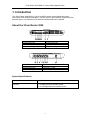
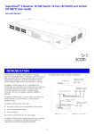
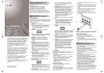
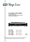
About the 3Com Router 3040
(1) Ethernet LED (LAN4)
(3) Ethernet LED (LAN2)
(5) ADSL2+ link LED (DSL LNK)
(7) System LED (SYS)
(2) Ethernet LED (LAN3)
(4) Ethernet LED (LAN1)
(6) ADSL2+ activity LED (DSL ACT)
(8) Power LED (PWR)
Front view of the 3Com Router 3040
(1) Power switch
(3) Console port (CONSOLE)
(5) Ethernet port 2(LAN2)
(7) Ethernet port 4 (LAN4)
(2) Power socket
(4) Ethernet port 1 (LAN1)
(6) Ethernet port 3 (LAN3)
(8) ADSL2+ over POTS interface (ADSL)
Rear view of the 3Com Router 3040
System Specifications
Item
Specification
Interface
1 console port
1 x 10 Mbps Ethernet interface (WAN)
4 x 10/100 Mbps Ethernet interfaces (LAN)
1
3Com Router 3000 ADSL2+ Family Getting Started Guide
LEDs
LED
Description
LAN0/LAN1/LAN2/LAN3/WAN
SYS
PWR
OFF means no link is present.
ON means a link is present.
Blinking means data is being sent or/and received on
the AUX port.
Blinking means the system is operating normally.
Steady ON or OFF means the system is improperly
operating.
OFF means no power is being supplied.
ON means power is being supplied.
Console port
Attribute
Connector
Interface standard
Baud rate
Service
Description
RJ45
Asynchronous RS232
9600 (default) to 115200 bps
Connection to an ASCII terminal
Connection to the serial interface on a PC to run the
terminal emulation program on the PC
Command line interface (CLI)
Auxiliary (AUX) port
Ethernet interface
Attribute
10BASE-T
Connector
Interface type
RJ45
MDI/MDIX auto-sensing
Operating mode
10 Mbps
Full duplex/half duplex
10/100BASE-T
10/100 Mbps auto-sensing
Full duplex/half duplex
Supports only L2 switching
2
3Com Router 3000 ADSL2+ Family Getting Started Guide
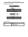
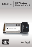
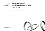
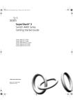
About the 3Com Router 3041
(1) Ethernet LED (LAN4)
(3) Ethernet LED (LAN2)
(5) ADSL2+ link LED (DSL LNK)
(7) ISDN link LED (ISDN LNK)
(9) System LED (SYS)
(2) Ethernet LED (LAN3)
(4) Ethernet LED (LAN1)
(6) ADSL2+ activity LED (DSL ACT)
(8) ISDN activity LED (ISDN ACT)
(10) Power LED (PWR)
Front view of the 3Com Router 3041
(1) Power switch
(3) Console port (CONSOLE)
(5) Ethernet port 2(LAN2)
(7) Ethernet port 4 (LAN4)
(2) Power socket
(4) Ethernet port 1 (LAN1)
(6) Ethernet port 3 (LAN3)
(8) ADSL2+ over POTS interface (ADSL)
Rear view of the 3Com Router 3041
System Specifications
Item
Specification
Interface
1 console port
4 x 10/100 Mbps Ethernet ports
1 ADSL2+ over POTS interface
1 ISDN BRI S/T interface
3
3Com Router 3000 ADSL2+ Family Getting Started Guide
LEDs
LED
Description
LAN1/LAN2/LAN3/LAN4
DSL LNK
DSL ACT
ISDN LNK
ISDN ACT
SYS
PWR
OFF means no link is present.
Steady ON means a link is present.
Blinking means the interface is sending and/or
receiving data.
OFF means no ADSL/ADSL2/ADSL2+ line is activated.
Steady ON means the ADSL/ADSL2/ADSL2+ line is
activated.
Blinking means the connected two parties are
negotiating parameters.
OFF means no data is being sent or received.
Blinking means the interface is sending and/or
receiving data.
OFF means the ISDN link is not activated.
ON means the ISDN link has been activated.
OFF means no data is being sent or received on the
ISDN link.
Blinking means data is being sent and/or received on
the ISDN link.
Blinking means the system is operating normally.
Steady ON or OFF means the system is improperly
operating.
OFF means no power is being supplied.
Steady ON means power is being supplied.
Console port
Attribute
Connector
Interface standard
Baud rate
Service
Description
RJ45
Asynchronous RS232
9600 (default) to 115200 bps
Connection to an ASCII terminal
Connection to the serial interface on a PC to run the
terminal emulation program on the PC
Command line interface (CLI)
Auxiliary (AUX) port
Ethernet interface
Attribute
10BASE-T
Connector
Interface type
RJ45
MDI/MDIX auto-sensing
Operating mode
10 Mbps
Full duplex/half duplex
10/100BASE-T
10/100 Mbps auto-sensing
Full duplex/half duplex
Supports only L2 switching
4
3Com Router 3000 ADSL2+ Family Getting Started Guide
2. Installing the Router
You can place your router on a sturdy tabletop or workbench or mount it on a vertical surface.
Placing the Router on a Tabletop/Workbench
When placing the router on a tabletop or workbench,
• Make sure that the tabletop or workbench is clean, flat, and sturdy.
• Allow 10 cm (3.9 in.) of clearance around the sides of the chassis.
• Do not stack multiple routers together.
Mounting the Router on a Vertical Surface
Mount the router on a vertical surface with four pan-head screws and the four brackets at the
bottom of the router.
Caution:
z
z
z
Securely anchor these four mounting screws in the vertical surface. If the screws are not
properly anchored, strain of the network cable connections can pull the router from the wall.
Install the router in such a position that the LEDs can be read easily.
Securely fix the external power supply unit of the router, preventing the power cord from falling
down.
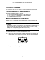
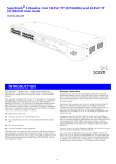
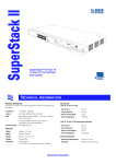
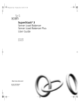
Follow these steps to mount the router on a wall or other vertical surface:
Step 1: Install four pan-head screws on a wall or other flat vertical surface (with reference to the
distance between the four brackets as shown below), and ensure that each screw sticks
out 6 mm (0.24 in.) on the wall.
Chassis bottom view
Step 2: Hang the router on the screws by the four brackets.
5
3Com Router 3000 ADSL2+ Family Getting Started Guide
Connecting the Ground Wire
Caution:
Properly connect the ground wire before connecting other cables and shorten it as much as
possible to prevent the router and the connected device from getting damaged during periods of
lightning activities.
The grounding screw of the chassis PGND is located on the rear panel. Connect this screw to the
earth ground using a ground wire. The grounding resistance must not be greater than 5-ohm.
Connecting the Power Cord
AC-input power supply
The Router 3000 external AC-input power supply is provided with these specifications:
• Input rated voltage: 100 to 240 Vac, 50 to 60 Hz
• Max. input tolerance: 90 to 264 Vac, 50 to 60 Hz
• Input current: 0.5 to 1A
• Output voltage: 12 Vdc
• Output current: 1.25 A
Power supply
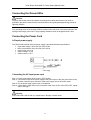
Connecting the AC-input power cord
Step 1: Put the power switch of the router in OFF position.
Step 2: Connect the output of the power supply to the power input on the rear panel of the router,
and then insert the input connector of the power supply into an AC power outlet.
Step 3: Put the power switch of the router in ON position.
Step 4: Check that the PWR LED on the front panel of the router is ON. If the LED is OFF, repeat
steps 2 through 4.
Caution:
If the PWR LED is still off after you repeat steps 2 through 4 several times.
6
3Com Router 3000 ADSL2+ Family Getting Started Guide
Connecting the Router to a Console Terminal
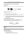
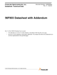
Console cable
The console cable has an RJ45 connector at one end and a DB9 (socket) connector at the other
end.
A
A
Console cable assembly
Connecting the console cable
Follow these steps to connect the router to a console terminal:
Step 1: Select a console terminal. The console terminal can be either a standard ASCII terminal
with an RS-232 serial interface or more commonly, a PC.
Step 2: Power off the router and the console terminal, and then connect the RS-232 serial port on
the console terminal to the console port on the router using the console cable. Verify the
connection and power on the router. In normal cases, the startup information is displayed
on the terminal screen.
Connecting the Router to LAN
The 10/100 Ethernet LAN interfaces on the Router 3000 support MDI/MDIX auto-sensing.
Therefore, you can connect your router to another device using either a straight-through or
crossover cable regardless of whether the two devices are the same type.
RJ-45 Ethernet cable
Caution:
In preparing network cables, shielded cables are preferred for the sake of electromagnetic
compatibility.
Verifying Installation
After you complete installation, verify that:
• The proper power supply is used.
• The grounding wire of the router is correctly connected.
• The console cable and the power cord are correctly connected.
7
3Com Router 3000 ADSL2+ Family Getting Started Guide
3. Safety Information
You must read the following safety information before carrying out any installation or removal of
components, or any maintenance procedures on the product.
WARNING: Warnings contain directions that you must follow for your personal safety. Follow all
directions carefully. You must read the following safety information carefully before operation,
installation or removal of the unit.
AVERTISSEMENT: Les avertissements présentent des consignes que vous devez respecter
pour garantir votre sécurité personnelle. Vous devez respecter scrupuleusement toutes les
consignes. Nous vous demandons de lire attentivement les consignes de sécurité suivantes
avant d'installer ou de retirer l'unité.
VORSICHT: Warnhinweise enthalten Anweisungen, die Sie zu Ihrer eigenen Sicherheit befolgen
müssen. Alle Anweisungen sind sorgfältig zu befolgen. Sie müssen die folgenden
Sicherheitsinformationen' sorgfältig durchlesen, bevor Sie das Gerät installieren oder ausbauen.
ADVERTENCIA: Las advertencias contienen indicaciones que debe respetar por su seguridad
personal. Siga las indicaciones con cuidado. Antes de utilizar, instalar o extraer la unidad, debe
leer detenidamente la siguiente información de seguridad.
AVVERTENZA: Le avvertenze contengono istruzioni indispensabili per assicurare la sicurezza
personale. Seguire attentamente tutte le indicazioni fornite. Prima di avviare, installare o
rimuovere l'unità, leggere attentamente le seguenti informazioni di sicurezza.
OSTRZEŻENIE: Ostrzeżenia zawierają wskazówki, których należy przestrzegać dla własnego
bezpieczeństwa. Należy uważnie przestrzegać wszystkich wskazówek. Przed użyciem, instalacją
lub demontażem urządzenia należy przeczytać poniższe informacje o bezpieczeństwie.
Power Cord Set – Japan
8
3Com Router 3000 ADSL2+ Family Getting Started Guide
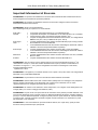
Important Safety Information
WARNING: Installation and removal of Router 3000 units must be carried out by qualified personnel only.
WARNING: The unit must be connected to an earthed power supply to ensure compliance with safety
standards.
WARNING: Power Cord Set:
This must be approved for the country where it is used.
U.S.A. and
The cord set must be UL-approved and CSA certified.
Canada
The minimum specification for the flexible cord is:
No. 18 AWG
Type SV or SJ
3-conductor
The cord set must have a rated current capacity of at least 10A.
The attachment plug must be an earth-grounding type with a NEMA 5-15P (15A,
125V) or NEMA 6-15P (15A, 250V) configuration.
United Kingdom
The supply plug must comply with BS1363 (3-pin 13 amp) and be fitted with a 5A
Only
fuse that complies with BS1362.
The mains cord must be <HAR> or <BASEC> marked and be of type
H03VVF3GO.75 (minimum).
Europe Only
The supply plug must comply with CEE 7/7 ("SCHUKO").
The mains cord must be <HAR> or <BASEC> marked and be of type
H03VVF3GO.75 (minimum).
Denmark
The supply plug must comply with section 107-2-D1, standard DK2-1a or DK25a.
Switzerland
The supply plug must comply with SEV/ASE 1011.
WARNING: France and Peru only:
†
This unit cannot be powered from IT supplies. If your supplies are of IT type, this unit must be powered by
230V (2P+T) via an isolation transformer ratio 1:1, with the secondary connection point labeled Neutral,
connected directly to earth (ground).
†
Impédance à la terre.
WARNING: The appliance coupler (the connector to the unit and not the wall plug) must have a
configuration for mating with an EN60320/IEC320 appliance inlet.
WARNING: The socket outlet must be near to the unit and easily accessible.
WARNING: This unit operates under SELV (Safety Extra Low Voltage) according to IEC 60950. The
conditions are only maintained if the equipment to which it is connected also operates under SELV
conditions.
WARNING: To avoid electric shock or damage to the equipment, do not connect Safety-Extra-Low-Voltage
(SELV) circuits to telephone-network-voltage (TNV) circuits.
WARNING: RJ-45 Ports. These are shielded RJ-45 data sockets. They cannot be used as standard
traditional telephone sockets, or to connect the unit to a traditional PBX or public telephone network. Only
connect RJ-45 data connectors, network telephony systems, or network telephones to these sockets.
Either shielded or unshielded data cables with shielded or unshielded jacks can be connected to these data
sockets.
WARNING: If installing products of different depths together (one on top of the other), the shallower
products should be installed above the deeper products.
9
3Com Router 3000 ADSL2+ Family Getting Started Guide
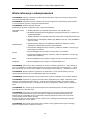
L'information de Sécurité Importante
AVERTISSEMENT: L'installation et la dépose des unités Router 5000 et 6000 Series doivent être confiées à
un personnel qualifié.
AVERTISSEMENT: Brancher l'unité à une source de courant mise à la terre pour assurer la conformité aux
normes de sécurité.
AVERTISSEMENT: Cordon électrique:
Il doit être agréé ans le pays d'utilisation:
Etats-Unis et
Canada
Danemark
Europe
Suisse
Le cordon doit avoir reçu l'homologation des UL et un certificat de la CSA
Le cordon souple doit respecter, à titre minimum, les spécifications suivantes :
calibre 18 AWG
type SV ou SJ
à 3 conducteurs
Le cordon doit être en mesure d'acheminer un courant nominal d'au moins 10 A
La prise femelle de branchement doit être du type à mise à la terre (mise à la
masse) et respecter la configuration NEMA 5-15P (15 A, 125 V) ou NEMA 6-15P
(15 A, 250 V)
La prise mâle d'alimentation doit respecter la section 107-2 D1 de la norme DK2
1a ou DK2 5a
La prise secteur doit être conforme aux normes CEE 7/7 ("SCHUKO")
Le cordon secteur doit porter la mention <HAR> ou <BASEC> et doit être de type
HO3VVF3GO.75 (minimum).
La prise mâle d'alimentation doit respecter la norme SEV/ASE 1011
AVERTISSEMENT: France et Pérou uniquement:
Ce groupe ne peut pas être alimenté par un dispositif à impédance à la terre. Si vos alimentations sont du
type impédance à la terre, ce groupe doit être alimenté par une tension de 230 V (2 P+T) par le biais d'un
transformateur d'isolement à rapport 1:1, avec un point secondaire de connexion portant l'appellation Neutre
et avec raccordement direct à la terre (masse).
AVERTISSEMENT: Le coupleur d'appareil (le connecteur du groupe et non pas la prise murale) doit
respecter une configuration qui permet un branchement sur une entrée d'appareil EN60320/CEI 320.
AVERTISSEMENT: La prise secteur doit se trouver à proximité de l'appareil et son accès doit être facile.
AVERTISSEMENT: Cette unité fonctionne dans des conditions de très basse tension de sécurité et de
tension de réseau téléphonique conformes à la norme CEI60950. Ces conditions sont garanties uniquement
si l'équipement auquel l'unité est raccordée fonctionne dans les mêmes conditions.
AVERTISSEMENT: Pour éviter tout choc électrique ou dommage à l'équipement, ne reliez pas les circuits
de très basse tension de sécurité aux circuits de tension de réseau téléphonique.
AVERTISSEMENT: Points d'accès RJ-45. Ceux-ci sont protégés par des prises de données. Ils ne peuvent
pas être utilisés comme prises de téléphone conventionnelles standard, ni pour la connection de l'unité à un
réseau téléphonique central privé ou public. Raccorder seulement connecteurs de données RJ-45,
systèmes de réseaux de téléphonie ou téléphones de réseaux à ces prises.
Il est possible de raccorder des câbles protégés ou non protégés avec des jacks protégés ou non protégés
à ces prises de données.
AVERTISSEMENT: Si vous installez des produits de profondeur différente ensemble (l'un sur l'autre),
placez le produit le moins encombrant sur le produit le plus encombrant.
10
3Com Router 3000 ADSL2+ Family Getting Started Guide
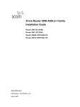
Wichtige Sicherheitsinformationen
VORSICHT: Einheiten der Router-Serie 5000 und 6000 dürfen nur von qualifiziertem Fachpersonal
installiert bzw. deinstalliert werden.
VORSICHT: Das Gerät muß an eine geerdete Steckdose angeschlossen werden, die europäischen
Sicherheitsnormen erfüllt.
VORSICHT: Der Anschlußkabelsatz muß mit den Bestimmungen des Landes übereinstimmen, in dem er
verwendet werden soll.
USA und
Kanada
GB
Europa
Dänemark
Schweiz
Das Kabel muss UL-zugelassen und von der CSA abgenommen sein
Mindestanforderungen an das flexible Netzkabel: Nr. 18 AWG Tpe SV- oder SJ 3Leiter
Das Kabel muss eine Nennbelastbarkeit von mindestens 10 A aufweisen
Der Netzstecker muss über eine Erdung verfügen und entweder der Konfiguration
NEMA 5-15P (15 A, 125 V) oder NEMA 6-15P (15 A, 250 V) entsprechen
Der Stecker muss mit BS1363 (dreipolig, 13 A) konform und mit einer 5-A-Sicherung
ausgestattet sein, die mit BS1362 konform ist
Das Netzkabel muss vom Typ HO3VVF3GO.75 (Mindestanforderung) sein und die
Aufschrift <HAR> oder <BASEC> tragen
Der Netzstecker muß die Norm CEE 7/7 erfüllen ("SCHUKO")
Das Netzkabel muß vom Typ HO3VVF3GO.75 (Mindestanforderung) sein und die
Aufschrift <HAR> oder <BASEC> tragen
Der Netzstecker muss die in Abschnitt 107-2-D1 der Norm DK2-1a oder DK2-5a
aufgeführten Bestimmungen erfüllen
Der Stecker muss mit SEV/ASE 1011 konform sein
VORSICHT: Nur für Frankreich und Peru:
†
Diese Einheit kann nicht über Netzteile vom Typ IT mit Strom versorgt werden. Wenn Ihre Netzteile vom
Typ IT sind, muss diese Einheit über einen Trenntransformator, 1:1-Verhältnis, mit 230 Volt (2P+T) versorgt
werden. Der sekundäre Anschlusspunkt mit der Bezeichnung Neutral muss dabei direkt an die Erdung
angeschlossen sein.
†
Impédance à la terre
VORSICHT: Der Gerätestecker (der Anschluß an das Gerät, nicht der Wandsteckdosenstecker) muß eine
passende Konfiguration für einen Geräteeingang gemäß EN60320/IEC320 haben.
VORSICHT: Die Netzsteckdose muß in der Nähe des Geräts und leicht zugänglich sein.
VORSICHT: Diese Einheit arbeitet unter SELV-Bedingungen (SELV = Safety Extra Low Voltage) und TNVBedingungen (TNV = Telephone-network-voltage) gemäß IEC 60950. Die hiermit verknüpften Bedingungen
sind nur dann erfüllt, wenn Geräte, mit denen diese Einheit verbunden ist, ebenfalls unter SELV- und/oder
TNV-Bedingungen arbeiten.
VORSICHT: Damit elektrische Schläge oder Schäden an den Geräten vermieden werden, verbinden Sie
keine SELV (Safety-Extra-Low-Voltage)-Stromkreise mit TNV (Telephone-network-voltage)-Stromkreisen.
VORSICHT: RJ-45-Porte. Diese Porte sind geschützte Datensteckdosen. Sie dürfen weder wie normale
traditionelle Telefonsteckdosen noch für die Verbindung der Einheit mit einem traditionellem privatem oder
öffentlichem Telefonnetzwerk gebraucht werden. Nur RJ-45-Datenanscluße, Telefonnetzsysteme or
Netztelefone an diese Steckdosen anschließen.
Entweder geschützte oder ungeschützte Buchsen dürfen an diese Datensteckdosen angeschlossen werden.
VORSICHT: Werden Produkte mit unterschiedlicher Tiefe übereinander installiert, sind die flacheren
Produkte auf den tieferen zu installieren.
11
3Com Router 3000 ADSL2+ Family Getting Started Guide
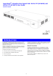
Información de Seguridad Importante
ADVERTENCIA: La instalación y retirada de las unidades del Router serie 5000 y 6000 sólo debe llevarla a
cabo personal cualificado.
ADVERTENCIA: Conecte la unidad a una fuente de alimentación con toma de tierra para garantizar el
cumplimiento de las normas de seguridad.
ADVERTENCIA: Conjunto de cables eléctricos:
Debe estar homologado para el pa's donde se utilice:
EE.UU. y Canadá
Sólo para el Reino
Unido
Sólo para Europa
Dinamarca
Suiza
El conjunto de cables debe estar homologado por UL y tener la certificación
CSA.
La especificación m'nima del cable flexible es: Nº 18 AWG Tipo SV o SJ Tres
conductores
El conjunto de cables debe tener una capacidad de corriente nominal de al
menos 10 A.
El enchufe de conexión debe ser de tipo de toma de tierra con una
configuración NEMA 5-15P (15 A, 125 V) o NEMA 6-15P (15 A, 250 V).
La toma de alimentación debe cumplir la norma BS1363 (3 patillas, 13 A) e
instalarse con un fusible de 5 A que cumpla BS1362.
El cable de alimentación de red debe tener la marca <HAR> o <BASEC> y ser
de tipo H03VVF3GO.75 (m'nimo).
La toma de alimentación debe cumplir la norma CEE 7/7 ("SCHUKO").
El cable de alimentación de red debe tener la marca <HAR> o <BASEC> y ser
de tipo H03VVF3GO.75 (m'nimo).
La toma de alimentación debe cumplir la sección 107-2-D1 de la norma DK2-1a
o DK2-5a
La toma de alimentación debe cumplir la norma SEV/ASE 1011.
†
ADVERTENCIA: Sólo para Francia y Perú: esta unidad no puede recibir corriente de fuentes IT . Si las
fuentes de suministro de corriente son de tipo IT, esta unidad debe recibir 230 V (2P+T) a través de un
transformador aislador con relación 1:1, con el punto de conexión secundario etiquetado como neutro
conectado directamente a tierra.
†
Impédance à la terre
ADVERTENCIA: El acoplador del equipo (el conector para la unidad y no la toma de la pared) debe tener
una configuración que se adapte a una entrada del equipo EN60320/IEC320.
ADVERTENCIA: El enchufe debe estar cerca de la unidad y ser de fácil acceso.
ADVERTENCIA: Esta unidad funciona en condiciones SELV (voltaje extrabajo de seguridad) y TNV (voltaje
de redes telefónicas) de conformidad con la norma IEC 60950. Las condiciones sólo se mantienen si el
equipo al que esté conectada la unidad también funciona en condiciones SELV o TNV.
ADVERTENCIA: Para evitar descargas eléctricas o daños al equipo, no conecte los circuitos SELV (voltaje
extrabajo de seguridad) a los circuitos TNV (voltaje de redes telefónicas).
ADVERTENCIA: Puertos RJ-45. Son conectores de datos RJ-45 blindados. No pueden utilizarse como
tomas de teléfono tradicionales estándar ni para conectar la unidad a una central de conmutación PBX
tradicional ni a una red telefónica p?blica. Conecte sólo conectores de datos RJ-45, sistemas de telefon'a
de red local o teléfonos de red local a estas tomas.
Pueden conectarse cables de datos blindados o sin blindaje con clavijas blindadas o sin blindaje a estos
conectores de datos.
ADVERTENCIA: Si instala juntos productos de diferente altura (uno encima de otro), los de menor altura
deben instalarse encima.
12
3Com Router 3000 ADSL2+ Family Getting Started Guide
Importanti Informazioni di Sicurezza
AVVERTENZA: Le operazioni di installazione e rimozione delle unità Router 5000 e 6000 Series devono
essere eseguite esclusivamente da personale qualificato.
AVVERTENZA: Per rispettare gli standard di sicurezza, è necessario collegare l'unità a una fonte di
alimentazione dotata di messa a terra.
AVVERTENZA: Set dei cavi di alimentazione
Deve essere approvato per il paese in cui viene utilizzato
Stati Uniti e
Canada
Solo Regno
Unito
Solo Europa
Danimarca
Svizzera
Il cavo deve avere l'approvazione UL e la certificazione CSA
La specifica minima per il cavo flessibile è: N. 18 AWG Tipo SV o SJ 3 conduttori
Il set di cavi deve avere una capacità nominale di almeno 10 A.
La spina di collegamento deve essere dotata di messa a terra, con configurazione
NEMA 5-15P (15 A, 125 V) o NEMA 6-15P (15 A, 250 V).
La spina di alimentazione deve essere conforme BS1363 (3 pin 13 amp) e dotata
di un fusibile da 5 A conforme BS1362.
Il cavo dell'alimentazione di rete deve essere contrassegnato dai marchi <HAR> o
<BASEC> ed essere di tipo H03VVF3GO.75 (minimo).
La spina di alimentazione deve essere conforme CEE 7/7 (tipo "SCHUKO").
Il cavo dell'alimentazione di rete deve essere contrassegnato dai marchi <HAR> o
<BASEC> ed essere di tipo H03VVF3GO.75 (minimo).
La spina di alimentazione deve essere conforme alla sezione 107-2-D1, standard
DK2-1a o DK2
La spina di alimentazione deve essere conforme SEV/ASE 1011
†
AVVERTENZA: Solo per Francia e Perù. Questa unità non può ricevere alimentazione di tipo IT . Se
l'alimentazione è di tipo IT, l'unità deve essere alimentata a 230 V (2P+T) tramite un trasformatore di
isolamento con rapporto 1:1, con il punto di collegamento secondario contrassegnato come Neutro,
collegato direttamente a terra.
†
Impédance à la terre.
AVVERTENZA: L'accoppiatore (il connettore all'unità e non la spina a muro) deve avere una configurazione
abbinabile a una presa EN60320/IEC320.
AVVERTENZA: La presa deve trovarsi vicino all'unità ed essere facilmente accessibile.
AVVERTENZA: Questa unità funziona alle condizioni SELV (Safety Extra Low Voltage) e TNV (Telephone
Network Voltage) previste dalla norma IEC 60950. Tali condizioni sono mantenute solo se anche
l'apparecchiatura a cui è collegata opera nelle stesse condizioni.
AVVERTENZA: Per evitare scosse elettriche o danni al dispositivo, non collegare circuiti Safety-Extra-LowVoltage (SELV) con circuiti a voltaggio rete telefonica (TNV).
AVVERTENZA: Le porte RJ-45 sono prese dati RJ-45 schermate. Non è pertanto possibile utilizzarle come
normali prese telefoniche né per collegare l'unità a un PBX (Private Branch Exchange, centralino telefonico
privato) o a una rete telefonica pubblica. Collegare a queste porte solo prese dati RJ-45, sistemi di telefonia
o telefoni di rete. A queste prese dati è possibile collegare cavi dati schermati o non schermati con prese
dati schermate o non schermate.
AVVERTENZA: In caso di installazione di prodotti di altezze diverse (uno sopra l'altro), quelli più bassi
dovranno essere posizionati sopra quelli più alti.
13
3Com Router 3000 ADSL2+ Family Getting Started Guide
Ważne informacje o zabezpieczeniach
OSTRZEŻENIE: Instalacja i demontaż urządzenia Router 5000 series i 6000 series mogą być wykonywane
tylko przez wykwalifikowany personel.
OSTRZEŻENIE: Urządzenie musi być uziemione lub musi być podłączone do uziemionego źródła zasilania
w celu zapewnienia zgodności z wymogami bezpieczeństwa.
OSTRZEŻENIE: Zestaw przewodów zasilania:
Niezbędna jest zgodność z przepisami kraju, w którym jest stosowany
Stany Zjednoczone
i Kanada
Zestaw przewodów musi posiadać zezwolenie UL oraz certyfikat CSA.
Minimalna specyfikacja przewodu giętkiego: Przewód typu SV lub SJ 3 o średnicy 18
wg specyfikacji AWG.
Zestaw przewodów musi posiadać pojemność prądu znamionowego przynajmniej 10A.
Wtyczka musi być uziemiająca z układem typu NEMA 5-15P (15A, 125V) lub NEMA 615P (15A, 250V).
Wielka Brytania
Wtyczka musi być zgodna z normą BS1363 (3-pinowa 13 amperów) i musi być
wyposażona w bezpiecznik 5A zgodny z normą BS1362.
Przewód sieci zasilającej musi być oznaczony <HAR> lub <BASEC> i musi być typu
H03VVF3g0.75 (minimum).
Europa
Wtyczka zasilająca musi być zgodna z normą CEE 7/7 („SCHUKO”).
Przewód sieci zasilającej musi być oznaczony <HAR> lub <BASEC> i musi być typu
H03VVF3g0.75 (minimum).
Dania
Wtyczka zasilająca musi być zgodna z sekcją 107-2-D1 normy DK2-1a lub DK2-5a.
Szwajcaria
Wtyczka zasilająca musi być zgodna z normą SEV/ASE 1011.
†
OSTRZEŻENIE: Tylko Francja i Peru: Urządzenie nie może być zasilane zasilaczem IT . Jeśli zasilacze są
typu IT, urządzenie to musi być zasilane napięciem 230V (2P+T) z transformatora separującego 1:1, a drugi
bolec wtyczki musi być oznaczony jako Neutral i musi być bezpośrednio uziemiony. † Impédance à la terre
OSTRZEŻENIE: Złączka urządzenia (podłączona do przełącznika, a nie do wtyczki ściennej) musi być
odpowiednio dopasowana do normy EN60320/IEC320 otworu wlotowego.
OSTRZEŻENIE: Gniazdo zasilające musi być umieszczone w pobliżu urządzenia i musi być łatwo dostępne.
OSTRZEŻENIE: Urządzenie to pracuje w warunkach SELV (Safety Extra Low Voltage – Bezpieczne niskie
napięcie) i TNV (telephone-network-voltage – napięcie sieci telefonicznej) zgodnie z normą IEC 60950.
Takie warunki są zachowane tylko, jeśli osprzęt, do którego jest podłączone, również pracuje w warunkach
SELV.
OSTRZEŻENIE: Aby uniknąć ryzyka porażenia prądem lub uszkodzenia sprzętu, nie należy podłączać
obwodów SELV do obwodów TNVs.
OSTRZEŻENIE: Porty RJ-45. Są to ekranowane gniazda danych RJ-45. Nie mogą być używane jako
tradycyjne gniazda telekomunikacyjne lub stosowane do podłączenia urządzenia do publicznej sieci
telefonicznej lub centrali PBX. Do tych gniazd należy podłączać jedynie łącza danych RJ-45, sieciowe
systemy telefoniczne lub telefony sieciowe.
Zarówno osłonięte, jak i nieosłonięte przewody z danymi wraz z osłoniętymi lub nieosłoniętymi wtykami
mogą być podłączone do tych gniazd.
OSTRZEŻENIE: W przypadku montowania razem urządzeń o różnych głębokościach (jedno na drugim)
węższe urządzenia należy ustawiać na szerszych.
14
3Com Router 3000 ADSL2+ Family Getting Started Guide
15