1
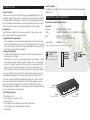
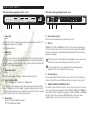
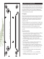
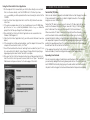
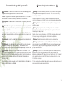
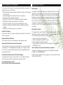
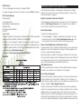
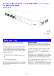
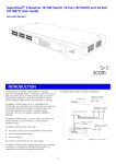
Installation Guide
OfficeConnect
®
Managed Gigabit Switch (3CDSG8)
INTRODUCTION
About This Guide:
Thank you for purchasing the 3Com® OfficeConnect® Managed Gigabit Switch. This
high quality, Gigabit Ethernet Switch is an easy, efficient way of creating or expanding
an existing network and managing it centrally. The Switch’s Gigabit ports provide support for bandwidth intensive applications, and allow high speed connections to servers,
and to the rest of the network. An example configuration is shown in Figure 1.
GreenConnect
Your OfficeConnect Gigabit Switch employs a number of initiatives to ensure your
product uses the least amount of power possible:
1. High Efficiency Power Adapter
The Power Adapter is a model specially designed to meet the Energy Star™ requirements for operating efficiency and also very low standby power when not connected
to the switch. These two features ensures your power adapter now uses substantially
less power than a conventional linear adapter.
2. Energy Saving Modes
Your OfficeConnect Gigabit Switch employs the latest technology to minimise the
amount of power it consumes.
When a port on the switch is not connected to a cable, or the link partner is turned
off or removed, the switch reduces the power on that port until it is connected again.
Also the switch detects the length of cable connected to its port and optimizes the
power on the port to reach the end device. Thus for shorter cables lengths it will
reduce the power output thereby achieving further reduction in power consumption.
You can be confident that your Switch will be taking the least amount of power but
still providing the performance that you have come to expect from OfficeConnect.
The Switch is compact and attractively designed for desktop use. It can be used with
other units in the OfficeConnect family, which include Cable/DSL gateways, wireless
devices, Fast Ethernet and Gigabit Ethernet switches. The OfficeConnect family is a
fully integrated system, enabling you to share computer resources, and take advantage
of new technologies as your network grows.
Your Package Contains:
• OfficeConnect Switch
• Power adapter for use with the Switch
• Four rubber feet
• This Installation Guide including Support and Safety Information
• CD Containing a User Guide and Application software
• Warranty flyer
2
About This Guide
This guide will use the term Switch when referring to the OfficeConnect managed
Gigabit Switch.
DIMENSIONS AND STANDARDS
Dimensions and Operating Conditions
Standards
Functional:
ISO 8802/3, IEEE 802.3, 802.3u
Safety:
UL 60950-1, EN 60950-1, CSA 22.2 #60950-1, IEC60950-1
EMC:
EN 55022 Class A, EN 55024,
FCC Part 15 Class A* ICES-003 Class A
Environmental:
EN 60068 (IEC 68)
* Refer to Regulatory Notices in the Support and Safety Information Section.
Managed Gigabit
Switch 8
7.64W, 26.1 BTU/hr
power requriement
Height:
27 mm (1.06 in)
3CDSG8
Duplex
us
Port Stat
1
Power
Depth:
135.4 mm (5.33 in)
s
Statu
Module
e
Activ
2
= 1000
Green
7 8/SFP
6
ity
5
= Activ
4
Flash
3
00M,
w = 10/1
M, Yello
1
2
3
4
5
6
7
8
Full
On =
Half
Off =
Giga
aged
bit Swit
ch
Man
onnect
OfficeC
Width:
225 mm (8.08 in)
ABOUT YOUR SWITCH
OfficeConnect Managed Gigabit Switch - Rear
OfficeConnect Managed Gigabit Switch - Front
3CDSG8
Duplex
Port Status
Power
1
Status
Module
Active
2
3
1
2
3
4
5
6
7
8/SFP
Green = 1000M, Yellow = 10/100M, Flash = Activity
4
1
2
3
4
5
6
7
8
On = Full
Off = Half
OfficeConnect Managed Gigabit Switch
5
1
Power LED
Green
Indicates that the Switch is receiving power from the power adapter. If the LED is off
there may be a problem with the adapter.
Refer to Problem Solving.
2
Status LED
Green/Yellow
This LED is used to indicate the status of the system. When this LED is green and not
flashing, the system is operating normally. When the switch is booting up and during
firmware upgrades the LED will flash green. If the system has failed the Power On Self
Test (POST) the LED will illuminate yellow.
POWER
6
CONSOLE
SFP
7
8
9
6 Power Adapter Socket
Only use the power adapter that is supplied with the Switch.
7 SFP Port
1000BaseLX (3CSFP92) and 1000BaseSX (3CSFP91) transceivers are supported. Use
this interface to allow your Switch to connect across distances greater than 100m or
where electrical isolation is required. Appropriate multimode fiber cables will also be
required (not supplied).
SFP transceivers are hot-insertable and hot-swappable. You can remove them
from and inset them without having to power down the switch.
3
Use of non-3Com SFPs is not recommended. 3Com cannot guarantee
operation of the switch if non-3Com SFPs are used.
4
8 Console Interface
Use the supplied DB-9 to RJ45 serial cable to connect to the switch’s command line
interface. Default Settings are 38,400 baud, 8 data bits, no parity, no flow control.
5
9 10BASE-T/100BASE-TX/1000BASE-T Ports
Use suitable TP cable with RJ-45 connectors. You can connect your Switch to a workstation, or any other piece of equipment that has 10BASE-T/100BASE-TX/1000BASE-T
connectivity. Each port is capable of autosensing for 10 Mbps, 100 Mbps or 1000 Mbps
operation. All ports have an automatic MDI/MDIX feature, which means either
straight-through or crossover cable can be used to connect to any port.
Module Active LED
Green
This LED is used to indicate that an SFP module is inserted and is active.
Eight/ Port Status LEDs
Green (1000 Mbps link) / Yellow (10 or 100Mbps link)
If the LED is on, the link between the port and the next piece of equipment is OK. If
the LED is flashing, the link is OK and data is being transmitted or received. If the LED
is off, nothing is connected or the connected device is turned off, or there is a problem
with the connection (refer to the Problem Solving section).
Duplex LEDs
Green (10/100/1000 Mbps, full duplex) /
Off (10/100 Mbps, half duplex)
3
WARNING: RJ-45 ports.
These are shielded RJ-45 data sockets. They cannot be used as standard traditional
telephone sockets, or to connect the unit to a traditional PBX or public telephone
network. Only connect RJ-45 data connectors, network telephony systems, or network telephones to these sockets.
Either shielded or unshielded data cables with shielded or unshielded jacks can be
connected to these data sockets.
VORSICHT: RJ-45-Portes.
Diese Portes sind geschützte Datensteckdosen. Sie dürfen weder wie normale
traditionelle Telefonsteckdosen noch für die Verbindung der Einheit mit einem
traditionellenm privatenm oder öffentlichenm Telefonnetzwerk gebraucht werden.
Nur RJ-45- Datenansclußhlüsse, Telefonnetzsysteme oder Netztelefone an diese
Steckdosen anschließen. Entweder geschützte oder ungeschützte Buchsen dürfen
an diese Datensteckdosen angeschlossen werden.
AVERTISSEMENT : Prises RJ-45 blindées.
Ces prises ne peuvent servir comme prises telephone standard et ne permettent pas
la connexion de l'appareil à un système PBX ni à un réseau téléphonique public.
N'y branchez que des prises RJ-45 mâles adaptées, ou des systèmes de réseaux
téléphoniques. Il est possible d'y brancher des câbles blindés ou non comportant
des prises de type Jack (blindées ou non).
1. POSTIONING YOUR SWITCH
Safety Information
WARNING: Please read the ‘Important Safety Information’ section in the
Support and Safety Information sheet before you start.
VORSICHT: Bitte lesen Sie den Abschnitt ‘Wichtige Sicherheitsinformationen’
sorgfältig durch, bevor Sie das Gerät einschalten.
AVERTISSEMENT: Veuillez lire attentivement la section "Consignes
importantes de sécurité" avant de mettre en route.
4
When positioning your Switch, ensure:
• It is out of direct sunlight and away from sources of heat.
• Cabling is away from power lines, fluorescent lighting fixtures, and sources of electrical noise such as radios, transmitters and broadband amplifiers.
• Water or moisture cannot enter the case of the unit.
• Air flow around the unit and through the vents in the side of the case is not restricted.
3Com recommends you provide a minimum of 25 mm (1 in.) clearance.
Using the Rubber Feet
Use the four self-adhesive rubber feet to prevent your Switch from moving around on
your desk, or when stacking with flat top OfficeConnect units. Only stick the feet to
the marked areas at each corner on the underside of your Switch.
Wall Mounting
There are two slots on the underside of the Switch that can be used for wall mounting. The Switch must be mounted with the LEDs facing upwards. When wall mounting the unit, ensure it is within reach of the power Outlet When wall mounting the
unit, ensure that the rubber feet are not fixed.
Mounting Instructions for Cement Walls
1 Make two holes 150 mm (5.9 in.) apart and insert two nylon or similar screw
anchors that are suitable for the wall construction.
2 Fix two suitable screws into the anchors, leaving their heads 3 mm (0.12 in.) clear of
the wall surface. The screws should be at least 30 mm (1.2 in.) long,
3 Remove any connections in the Switch and locate it over the screw heads. When in
line, gently push the Switch on to the wall and move it downwards to secure.
Mounting Instructions for Wood Walls
1 Make two holes 150 mm (5.9 in.) apart.
2 Fix two suitable screws directly into the wall, leaving their heads 3 mm (0.12 in.)
clear of the wall surface. The screws should be at least 20 mm (0.75 in.) long,
3 Remove any connections in the Switch and locate it over the screw heads. When in
line, gently push the Switch on to the wall and move it downwards to secure.
CAUTION: When making connections, be careful not to push the Switch up
and off the wall.
2. SETTING UP FOR MANAGEMENT
Managed Gigabit Switch 150mm apart
Wall mounting template
Your Switch can operate in its default state, that is, you can install it and it will work
straight away (plug-and-play). However, to make full use of the features offered by the
Switch, and to change and monitor the way it works, you have to access the management software that resides on the Switch. This is known as managing the Switch.
Managing the Switch can help you to improve the efficiency of the Switch and therefore the overall performance of your network.
IP Configuration
When the switch is powered up and connected to a network, the switch will obtain an
address from the DHCP server. If there is no DHCP server available, the switch will use
a default IP address of 169.254.xx.yy, where xx and yy are the last two bytes of the
MAC address. This default IP address is also printed on the label attached to the
underside of your switch.
Before you can manage your switch, you will need to determine it’s IP address to allow
a web browser to connect to it. You can do this either by connecting your workstation
to the console interface using the cable supplied, or using the 3Com Switch Detect
application that can be found on the CD that was supplied with the Switch.
Please follow the instructions below to determine and/or configure the IP address of
your switch.
Using the Console Interface
1. Connect the DB-9 to RJ-45 serial cable between your workstation (to it’s COM port)
and the Switch. Take care not to connect it to a data port on the Switch.
2. Using a terminal emulator program, for example HyperTerminal, connect to the
appropriate COM port on the workstation and ensure the following parameters are
set: 38400 baud, 8 data bits, no parity, 1 stop bit and no flow control.
3. If the Switch is not already powered up, power it up now and wait for the boot up
sequence to complete.
4. When the boot up sequence is completed, you will be presented with a login
prompt. The default username is admin. No password is required.
5. To show the IP address the switch is using, enter IP status and press Return. The
switch will display the IP address the switch is using. This address can now be used
in your preferred web browser to connect to the Switch User Interface. Use the
same username to log in.
6. If you want to manually assign an IP address, enter the following commands:
IP dhcp disable and press Return
IP Setup <IP Address> <ipmask> <gateway> and press Return
For example: IP Setup 192.168.1.2 255.255.255.0 192.168.1.1
You can now direct the web browser at the 192.168.1.2 address.
5
Using the 3Com Switch Detect Application
1. On the computer that is connected to your Switch (either directly or on a network
that is on the same subnet), insert the CD-ROM into its CD drive. If you have
autorun enabled, you will be presented with a menu showing the contents of the
CD-ROM.
2. Select the 3Com Detect Application link to install the utility. Follow the onscreen
instructions.
3. If the auto-run program does not start, you should browse to your CD-ROM drive,
go to the /switch detect directory and double click on setup.exe. Follow the
prompts that will take you through the installation process.
4. Once installed, the 3Com Switch Detect Application can be accessed from the
Windows Start/Programs list.
5. When the 3Com Detect application starts, you will be see the Welcome Screen (see
below).
6. If the computer has multiple network adapters, select the adapter that connects the
computer to the network or Switch, click "Next."
7. You will then be offered the choice of searching the same subnet that your PC is on
for a connected switch (default), or specifying an IP range. Note that specifying a
large range may take some time for the search to complete.
8. Once your Switch or Switches have been located, you will be presented with a list.
Select the switch to which you want to connect and click on "Open." Your default
Web browser will open and connect to the home page of the Switch.
6
3 CONNECTING WORKSTATIONS
Twisted Pair (TP) Cables
Cables can be shielded (screened) or unshielded. Cables must be Category 5 or above.
3Com recommends Category 5E or 6 cable for Gigabit connections. The maximum
length you can use is 100 m (328 ft).
Twisted Pair (TP) cable is very easy to use. To connect a TP cable, simply slot the connector into the relevant RJ-45 Port. When a connector is fully in, its latch locks into
place. To disconnect the cable, push the connector’s latch in and remove it.
When one end of a TP cable is connected to the Switch and the other end is connected to the network interface card of a workstation or other device, the Switch will
automatically detect whether a straight-through or crossover cable is being used and
will compensate if required. The units will then autonegotiate to determine the fastest
possible link speed between them. This may take a few seconds and the outcome will
be reflected in the LEDs on the front of the Switch.
If the equipment connected to the Switch does not support autonegotiation or it
has been disabled, it must be configured to operate in half duplex mode.
Expanding Your Network
You can increase the number of workstations and other devices that can connect to
your network by adding OfficeConnect gateways and switches. The Switch has automatic MDI/MDIX functionality. Simply plug in the cable and the Switch will automatically detect which wiring practice has been followed and will compensate accordingly.
4 PROBLEM SOLVING
For reference, the part number for the power adapter supplied for your region is:
The Switch has been designed to aid you when detecting and solving possible problems with your network. These problems are rarely serious; the cause is usually a disconnected or damaged cable, or incorrect configuration. If this section does not solve
your problem, contact your supplier for information on what to do next.
Perform these actions first:
• Ensure all network equipment is powered on.
• Power each piece of network equipment off, wait about five seconds and then
power each one on.
3C number
3C12VUS
3C12VUK
3C12VME
3C12VAA
3C12VSA
3C12VKR
3C12VRA
CAUTION: Do not power the Switch off and then immediately on. Wait about
five seconds between power cycles.
Check the following symptoms and solutions:
Power LED not lit.
This is probably because the switch does not have power. Check the following:
• Make sure the power lead from the power adapter is properly connected and the
cord is not damaged.
• Ensure the power adapter is correctly fitted into the power outlet socket and that
the socket switch is turned on if applicable.
• Ensure you are using only the 3Com power adapter supplied with the switch.
Power LED lit but Status LED illuminated yellow.
This indicates that the switch is receiving power, but for some reason the switch is not
operational. This is most likely due to a problem with the operational software in the
unit not loading correctly.
Refer to the diagnostic messages displayed on the command line interface (CLI) to
help identify the problem. If the software is corrupted, you can re-load the software
from the CLI. Please follow the instructions found in the User Guide for this Switch
which can be found on the on the CD which is supplied with your Switch or which
can be downloaded from www.3Com.com.
If there is still no power, contact 3Com Technical Support and ask for assistance.
Only use the power adapter supplied with the Switch or a replacement
OfficeConnect power adapter. Do not use any other power adapter.
Region
US and Canada
UK
Europe and Middle East
Australasia
South Africa
Korea
Argentina
If a software reload does not resolve the issue, contact 3Com Technical Support and
ask for assistance
Port Status LED not lit for a port that has a TP cable connected.
After connection, it may take several seconds for the Port Status LEDs to illuminate.
The Port Status LED should turn Green or Yellow, for each port that is connected.
If the Port Status LED is not lit after several seconds, ensure that the connected device
is powered on, that the TP cable is not damaged and that it is correctly inserted at
both ends.
You may find that a TP cable works when connected to the Switch, but does not work
if disconnected from the Switch and connected to another device. This may be
because the other device does not have the automatic MDI/MDIX feature.
7
Support and
Safety Information
8
Important Safety Information Consignes de sécurité importantes WARNING: Warnings contain directions you must follow for your personal
safety. Follow all directions carefully.
You must read the following safety information before carrying out any installation
or removal of the unit, or any maintenance procedures.
Avertissement: Ces avertissements sont à respecter pour votre sécurité.
Lisez-les attentivement.
WARNING: Exceptional care must be taken during installation and removal of
the unit.
Avertissement: L’installation et la désinstallation du matériel nécessite une
vigilance exceptionnelle.
WARNING: To ensure compliance with international safety standards this product must only be used with a power supply that is approved in the country of use.
The power supply output must be +12VDC, 1A minimum and the polarity of the
power supply output connector must comply with the marking on the unit.
Avertissement: Pour être conforme aux normes de sécurité internationales, ce
produit doit être utilisé exclusivement avec une alimentation aux normes du pays
d’utilisation.
WARNING: Disconnect the power adapter before moving the unit.
WARNING: This unit operates under SELV (Safety Extra Low Voltage) conditions
according to IEC 60950-1. The conditions are only maintained if the equipment to
which it is connected also operates under SELV conditions.
WARNING: RJ-45 Ports. These are shielded RJ-45 data sockets. They cannot be
used as standard traditional telephone sockets, or to connect the unit to a traditional PBX or public telephone network. Only connect RJ-45 data connectors, network telephony systems, or network telephones to these sockets.
Either shielded or unshielded data cables with shielded or unshielded jacks can be
connected to these data sockets.
Vous devez impérativement lire les consignes de sécurité suivantes avant de procéder
à l’installation ou à la désinstallation du matériel, ou à toute activité d’entretien.
La sortie de l’alimentation doit être de 12 V continus, 1A minimum, et les polarités
du connecteur de sortie doivent coïncider avec les indications figurant sur l’appareil.
Avertissement: Coupez systématiquement l’adaptateur secteur avant de
déplacer l’appareil.
Avertissement: Cet appareil fonctionne à très basse tension de sécurité (SELV,
Safety Extra Low Voltage) conformément à la norme IEC 60950-1. Pour ce faire, le
matériel auquel il est connecté doit également fonctionner sous SELV.
Avertissement: Ports RJ 45. Il s’agit de connecteurs de communication de
données blindés RJ 45. Il n’est pas possible de les utiliser comme prises téléphoniques
classiques ni de connecter l’appareil à un standard téléphonique classique ou à un
réseau téléphonique public. Seuls des connecteurs de réseau de données RJ 45, des
systèmes de téléphonie en réseau ou des téléphones réseau peuvent y être
branchés.
Vous pouvez y brancher des câbles pour réseau de données blindés ou non pourvus
de prises jack blindées ou non aux extrémités.
9
Wichtige Sicherheitsinformationen Importanti informazioni di sicurezza Warnung: Warnhinweise enthalten Anweisungen, die Ihrer persönlichen
Sicherheit dienen. Befolgen Sie all diese Anweisungen mit größter Sorgfalt.
Avvertenza: Queste avvertenze precisano le direttive da seguire per la propria
sicurezza personale. Conformarsi con la massima attenzione a quanto precisato.
Lesen Sie unbedingt die folgenden Sicherheitsinformationen, bevor Sie eine
Installation oder Entfernung des Gerätes vornehmen bzw. Wartungen/
Instandhaltungen durchführen.
Leggere con attenzione le informazioni relative alla sicurezza prima di procedere
all’installazione o alla rimozione dell’unità o a qualsiasi intervento di manutenzione.
Warnung: Bei der Installation und Entfernung des Gerätes ist mit äußerster
Sorgfalt vorzugehen.
Warnung: Um die Übereinstimmung mit den internationalen
Sicherheitsstandards zu gewährleisten, darf dieses Produkt nur mit einer
Stromversorgung betrieben werden, die den Bestimmungen des jeweiligen Landes
entspricht.
Die Netzsteckdose muss +12VDC, 1A minimal haben und die Polarität des
Netzanschlusses muss der Kennzeichnung auf dem Gerät entsprechen.
Warnung: Nehmen Sie vor dem Transport des Gerätes den Netzadapter ab.
Warnung: Dieses Gerät arbeitet gemäß IEC 60950-1 mit Schutzkleinspannung
(SELV = Safety Extra Low Voltage). Dieser Schutz bleibt nur erhalten, wenn die
angeschlossene Anlage ebenfalls über SELV verfügt.
Warnung: RJ-45 Anschluss. Dies sind abgeschirmte RJ-45-Datenbuchsen. Sie
können nicht als herkömmliche Standardtelefonbuchsen verwendet werden und
verbinden das Gerät nicht mit einer herkömmlichen Telefonanlage oder einem
öffentlichen Telefonnetz. Schließen Sie an diese Buchsen nur RJ-45Datenanschlüsse, Netzwerktelefonieanlagen oder Netzwerktelefone an.
An diese Datenbuchsen können abgeschirmte oder nicht abgeschirmte Stecker
angeschlossen werden.
10
Avvertenza: E’ necessario prestare la massima attenzione durante l’installazione e la rimozione dell’unità.
Avvertenza: Per garantire la piena conformità con gli standard di sicurezza
internazionali, il prodotto deve essere utilizzato con un’alimentazione approvata
nello specifico paese di utilizzo.
L’uscita dell’alimentazione deve essere +12V DC, 1A minimo e la polarità del
connettore dell’uscita dell’alimentazione dovrà conformarsi con la marcatura
riportata sull’unità.
Avvertenza: Scollegare l’adattatore di alimentazione prima di spostare l’unità.
Avvertenza: Quest’unità funziona in condizioni SELV (Safety Extra Low
Voltage) conformemente a IEC 60950-1. Tali condizioni potranno essere mantenute solo se l’apparecchiatura a cui è collega funziona similmente in condizioni
SELV.
Avvertenza: Porte RJ-45. Si tratta di prese dati schermate RJ-45. Non potranno
essere utilizzate come prese telefoniche tradizionali o per collegare l’unità ad una
normale rete PBS o telefonica pubblica. Collegare a queste prese solo connettori
RJ-45, sistemi di telefonia in rete o telefoni in rete.
A queste prese dati potranno essere collegati cavi dati schermati o meno con jack
schermati o meno.
Información de seguridad importante Advertencia: Las advertencias contienen instrucciones que debe seguir para su
seguridad personal. Siga todas las instrucciones atentamente.
Debe leer la siguiente información de seguridad antes de llevar a cabo la instalación
o extracción de la unidad, o cualquier procedimiento de mantenimiento.
Advertencia: Se debe extremar el cuidado durante la instalación y extracción
de la unidad.
Advertencia: Para asegurar la conformidad con los estándares de seguridad
internacionales, este producto sólo se puede usar con una fuente de alimentación
aprobada en el país de uso.
La salida de la fuente de alimentación debe ser de +12V CC, de 1A mínimo y la
polaridad del conector de salida de alimentación debe cumplir con la marca en la
unidad.
Advertencia: Desconecte el adaptador de alimentación antes de desplazar la
unidad.
Istotne Bezpieczeństwo Informacja Warning: Ostrzeżenia zawierają wskazówki, których należy przestrzegać w
celu zagwarantowania bezpieczeństwa osobistego. Do tych zaleceń należy
stosować się dokładnie.
Przed przystąpieniem do instalacji, usuwania urządzenia lub jakichkolwiek
czynności konserwacyjnych należy zapoznać się z instrukcjami bezpieczeństwa.
Warning: Podczas montażu lub demontażu urządzenia należy pracować z
wyjątkową uwagą.
Warning: Aby zapewnić zgodność z międzynarodowymi standardami
bezpieczeństwa, produkt należy wyłącznie używać w połączeniu z zasilaczem
zatwierdzonym w danym kraju.
Gniazdo zasilania musi mieć parametry +12VDC, 1A minimum, a biegunowość
złącza wyjściowego musi być zgodna z oznaczeniami na urządzeniu.
Warning: Przed przeniesieniem urządzenia należy odłączyć zasilacz.
Advertencia: Esta unidad opera bajo condiciones SELV (muy bajo voltaje de
seguridad) de acuerdo con la norma IEC 60950-1. Las condiciones sólo se
mantienen si el equipo al que está conectado también opera bajo condiciones SELV.
Warning: Urządzenie działa w warunkach SELV (obwód bezpiecznego niskiego
napięcia) zgodnie z normą IEC 60950-1. Warunki te są jednak zagwarantowane
wyłącznie wtedy, gdy sprzęt, do którego podłączone jest urządzenie, również
pracuje w obwodzie SELV.
Advertencia: Puertos RJ-45 Son enchufes de datos RJ-45 blindados. No se
pueden usar en los tradicionales enchufes telefónicos estándar, o para conectar la
unidad a una red PBX tradicional o red telefónica pública. Conecte únicamente a
estos enchufes los conectores de datos RJ-45, sistemas de telefonías de red o
teléfonos de red.
Warning: Porty RJ-45. Są to ekranowane gniazda RJ-45 do danych. Nie są
przeznaczone do użycia jako standardowe gniazda telefoniczne lub do
podłączenia urządzenia do PBX lub publicznej sieci telefonicznej. Do tych gniazd
wolno podłączać wyłącznie wtyki RJ-45 danych, systemów telefonii sieciowej
lub telefonów sieciowych.
A estos enchufes de datos se pueden conectar cables blindados o no blindados con
tomas hembra blindadas o no blindadas.
Do tych gniazd można podłączać kable danych ekranowane lub nieekranowane z
ekranowanymi lub nieekranowanymi wtykami.
11
ENVIRONMENTAL STATEMENTS
It is the policy of 3Com Corporation to be environmentally-friendly in all operations. To
uphold our policy, we are committed to:
• Establishing environmental performance standards that comply with national legislation and regulations.
• Conserving energy, materials and natural resources in all operations.
• Reducing the waste generated by all operations.
• Ensuring that all waste conforms to recognized environmental standards.
• Maximizing the recyclable and reusable content of all products.
• Ensuring that all products can be recycled, reused and disposed of safely.
• Ensuring that all products are labelled according to recognized environmental
standards.
• Improving our environmental record on a continual basis.
End Of Life Statement
3Com processes allow for the recovery, reclamation and safe disposal of all end-of-life
electronic components.
Regulated Materials Statement
3Com products do not contain any hazardous or ozone-depleting material.
Environmental Statement about the Documentation
The documentation for this product is printed on paper that comes from sustainable,
managed forests; it is fully biodegradable and recyclable, and is completely chlorinefree. The varnish is environmentally-friendly, and the inks are vegetable-based with a
low heavy-metal content.
Environmental Statement about the Product Packaging
The packaging for this product is fully recyclable. It has a recycled (post consumer)
waste content of at least 40% by weight, and no heavy-metal content.
For further details please refer to
http://www.3com.com/environment/index.html
12
REGULATORY NOTICES
FCC Statement
This equipment has been tested and found to comply with the limits for a Class A
digital device, pursuant to part 15 of the FCC Rules. These limits are designed to
provide reasonable protection against harmful interference when the equipment is
operated in a commercial environment. This equipment generates, uses and can radiate radio frequency energy and, if not installed and used in accordance with the
instructions, may cause harmful interference to radio communications. Operation of
this equipment in a residential area is likely to cause harmful interference to radio communications, in which case the user will be required to correct the interface at their
own expense.
Information to the User
If this equipment does cause interference to radio or television reception, which can be
determined by turning the equipment off and on, the user is encouraged to try to correct the interference by one or more of the following measures:
• Reorient or relocate the receiving antenna
• Relocate the equipment away from the receiver
• Move the equipment away from the receiver
• Plug the equipment into a different outlet so that equipment and receiver are on
different branch circuits.
How to identify and resolve radio-TV interference problems
This booklet is available from the U.S. Government Printing Office, Washington,
DC 20402, Stock No. 004-000-00345-4
In order to meet FCC emissions limits, this equipment must be used only with cables
that comply with IEEE 802.3.
ICES Statement
This Class A digital apparatus complies with Canadian ICES-003.
Cet appareil numérique de la classe A est conforme à la norme NMB-003 du Canada.
CE Statements (Europe)
EU Representative:
3Com Europe Limited
Peoplebuilding 2, Peoplebuilding Estate
Maylands Avenue
Hemel Hempstead, Hertfordshire
HP2 4NW
United Kingdom
This product complies with the European Low Voltage Directive 73/23/EEC as amended
by European Directive 93/68/EEC and EMC Directive 2004/108/EC.
Warning: This is a class A product. In a domestic environment this product may cause
radio interference in which case the user may be required to take adequate measures.
A copy of the signed Declaration of Conformity can be downloaded from the Product
Support web page at http://www.3com.com/
Also available at http://support.3com.com/doc/3CDSG8.pdf
China RoHS
OBTAINING SUPPORT FOR YOUR PRODUCT
3Com offers product registration, case management, and repair services through
eSupport.3com. You must have a user name and password to access these services,
which are described in this appendix.
Register Your Product to Gain Service Benefits
To take advantage of warranty and other service benefits, you must first register your
product at: http://eSupport.3com.com/. 3Com eSupport services are based on
accounts that are created or that you are authorized to access.
Solve Problems Online
3Com offers the following support tool:
• 3Com Knowledgebase — Helps you to troubleshoot 3Com products. This querybased interactive tool is located at: http://knowledgebase.3com.com. It contains thousands of technical solutions written by 3Com support engineers.
Purchase Extended Warranty and Professional Services
To enhance response times or extend your warranty benefits, you can purchase valueadded services such as 24x7 telephone technical support, software upgrades, onsite
assistance, or advanced hardware replacement.
Experienced engineers are available to manage your installation with minimal disruption to your network. Expert assessment and implementation services are offered to fill
resource gaps and ensure the success of your networking projects. For more information on 3Com Extended Warranty and Professional Services, see:
http://www.3com.com/
Contact your authorized 3Com reseller or 3Com for additional product and support
information. See the table of access numbers later in this appendix.
Access Software Downloads
You are entitled to bug fix / maintenance releases for the version of software that you
initially purchased with your 3Com product. To obtain access to this software, you
need to register your product and then use the Serial Number as your login. Restricted
Software is available at: http://eSupport.3com.com/
To obtain software releases that follow the software version that you originally purchased, 3Com recommends that you buy an Express or Guardian contract, a Software
Upgrades contract, or an equivalent support contract from 3Com or your reseller.
Support contracts that include software upgrades cover feature enhancements, incremental functionality, and bug fixes, but they do not include software that is released
by 3Com as a separately ordered product. Separately orderable software releases and
13
licenses are listed in the 3Com Price List and are available for purchase from your
3Com reseller.
Contact Us
3Com offers telephone, internet, and e-mail access to technical support and repair
services. To access these services for your region, use the appropriate telephone number, URL, or e-mail address from the table in the next section.
Telephone Technical Support and Repair
To obtain telephone support as part of your warranty and other service benefits, you
must first register your product at: http://eSupport.3com.com/
When you contact 3Com for assistance, please have the following information ready:
• Product model name, part number, and serial number
• A list of system hardware and software, including revision level
• Diagnostic error messages
• Details about recent configuration changes, if applicable
To send a product directly to 3Com for repair, you must first obtain a return materials
authorization number (RMA). Products sent to 3Com without authorization numbers
clearly marked on the outside of the package will be returned to the sender
unopened, at the sender’s expense. If your product is registered and under warranty,
you can obtain an RMA number online at http://eSupport.3com.com/. First-time
users must apply for a user name and password.
Telephone numbers are correct at the time of publication. Find a current directory of
3Com resources by region at: http://csoweb4.3com.com/contactus/
Country
Telephone Number
Asia, Pacific Rim — Telephone Technical Support and Repair
Australia
1800 075 316
Hong Kong
2907 0456
India
000 800 440 1193
Indonesia
001 803 852 9825
Japan
03 3507 5984
Malaysia
1800 812 612
New Zealand
0800 450 454
Philippines
1800 144 10220 or 029003078
P.R. of China
800 810 0504
Singapore
800 616 1463
South Korea
080 698 0880
14
Country
Taiwan
Thailand
Telephone Number
00801 444 318
001 800 441 2152
Pakistan Call the U.S. direct by dialing 00 800 01001, then dialing 800 763 6780
Sri Lanka Call the U.S. direct by dialing 02 430 430, then dialing 800 763 6780
Vietnam Call the U.S. direct by dialing 1 201 0288, then dialing 800 763 6780
You can also obtain non-urgent support in this region at this email address
[email protected]
Or request a return material authorization number (RMA) by FAX using this number:
+61 2 9937 5048, or send an email at this email address:
[email protected]
Country
Telephone Number
Europe, Middle East, and Africa — Telephone Technical Support and Repair
From anywhere in these regions not listed below, call: +44 1442 435529
From the following countries, call the appropriate number:
Austria
0800 297 468
Belgium
0800 71429
Denmark
800 17309
Finland
0800 113153
France
0800 917959
Germany
0800 182 1502
Hungary
06800 12813
Ireland
1 800 553 117
Israel
180 945 3794
Italy
800 879489
Luxembourg
800 23625
Netherlands
0800 0227788
Norway
800 11376
Poland
00800 4411 357
Portugal
800 831416
Russia
88005558588
Saudi Arabia
800 8 445 312
South Africa
0800 995 014
Spain
900 938 919
Sweden
020 795 482
Switzerland
0800 553 072
Country
U.A.E.
U.K.
Telephone Number
04-3908997
0800 096 3266
You can also obtain support in this region using this URL:
http://emea.3com.com/support/email.html
You can also obtain non-urgent support in this region at these email addresses:
Technical support and general requests: [email protected]
Return material authorization: [email protected]
Contract requests: [email protected]
Country
Telephone Number
Latin America — Telephone Technical Support and Repair
Antigua
AT&T +800 988 2112
Antigua Barbuda
AT&T +800 988 2112
Argentina
AT&T +800 988 2112
Aruba
AT&T +800 988 2112
Bahamas
AT&T +800 988 2112
Barbados
AT&T +800 988 2112
Belize
AT&T +800 988 2112
Bermuda
AT&T +800 988 2112
Bolivia
AT&T +800 988 2112
Brasil
0800-133266 (0800-13-3COM)
Brasil Local
+5511 5643 2700
British Virgin Islands
AT&T +800 988 2112
Cayman Islands
AT&T +800 988 2112
Chile
AT&T +800 998 2112
Colombia
AT&T +800 998 2112
Columbia Local
+571 592 5000
Costa Rica
AT&T +800 998 2112
Curaçao
AT&T +800 988 2112
Dominican Republic
AT&T +800 998 2112
El Salvador
AT&T +800 988 2112
Equador
AT&T +800 988 2112
French Guyana
AT&T +800 988 2112
Grenada
AT&T +800 988 2112
Guadalupe
AT&T +800 988 2112
Guatemala
AT&T +800 998 2112
Guyana
AT&T +800 988 2112
Haiti
AT&T +800 988 2112
Country
Telephone Number
Honduras
AT&T +800 998 2112
Jamaica
AT&T +800 988 2112
Mexico
1800 849 2273
Mexico Local
+52-55-52-01-0004
Monserrat
AT&T +800 998 2112
Nicaragua
AT&T +800 998 2112
Panama
AT&T +800 998 2112
Paraguay
AT&T +800 998 2112
Peru
AT&T +800 998 2112
Puerto Rico
AT&T +800 998 2112
Rest of Latin America
508 323 6234
St. Kitts Nevis
AT&T +800 998 2112
St. Lucia
AT&T +800 998 2112
St. Vincent
AT&T +800 998 2112
Suriname
AT&T +800 998 2112
Trinidad and Tobago
AT&T +800 998 2112
Turks and Caicos
AT&T +800 998 2112
Uruguay - Montevideo
AT&T +800 998 2112
Venezuela
AT&T +800 998 2112
Virgin Islands
AT&T +800 998 2112
You can also obtain support in this region in the following ways:
Spanish speakers, enter the URL:
http://lat.3com.com/lat/support/form.html
Portuguese speakers, enter the URL:
http://lat.3com.com/br/support/form.html
English speakers in Latin America should send e-mail to:
[email protected]
Country
Telephone Number
US and Canada — Telephone Technical Support and Repair
All locations: All 3Com products: 1 800 876 3266
15
COPYRIGHT AND TRADEMARKS
3Com Corporation, Corporate Headquarters, 350 Campus Drive, Marlborough, MA 01752-3064
Copyright © 2008 3Com Corporation. All rights reserved.
Copyright
No part of any documentation supplied with this product may be reproduced in any form or by any means or used to make any derivative work (such as translation, transformation,
or adaptation) without written permission from 3Com Corporation.
3Com Technologies reserves the right to revise any documentation supplied with this product and to make changes in content from time to time without obligation on the part
of 3Com Technologies to provide notification of such revision or change.
3Com Technologies provides any documentation supplied with this product without warranty, term, or condition of any kind, either implied or expressed, including, but not limited
to, the implied warranties, terms or conditions of merchantability, satisfactory quality, and fitness for a particular purpose. 3Com may make improvements or changes in the
product(s) and/or the program(s) described in any documentation supplied with this product at any time.
If there is any software on removable media described in any documentation supplied with this product, it is furnished under a license agreement included with the product as a
separate document, in the hard copy documentation, or on the removable media in a directory file named LICENSE.TXT or !LICENSE.TXT. If you are unable to locate a copy,
please contact 3Com and a copy will be provided to you.
UNITED STATES GOVERNMENT LEGEND
If you are a United States government agency, then any documentation supplied with this product and the software described therein are provided to you subject to the following:
All technical data and computer software are commercial in nature and developed solely at private expense. Software is delivered as "Commercial Computer Software" as defined
in DFARS 252.227-7014 (June 1995) or as a "commercial item" as defined in FAR 2.101(a) and as such is provided with only such rights as are provided in 3Com’s standard
commercial license for the Software. Technical data is provided with limited rights only as provided in DFAR 252.227-7015 (Nov 1995) or FAR 52.227-14 (June 1987), whichever
is applicable. You agree not to remove or deface any portion of any legend provided on any licensed program or documentation supplied to you in connection with this product.
Trademarks
Unless otherwise indicated, 3Com registered trademarks are registered in the United States and may or may not be registered in other countries.
3Com, the 3Com logo and OfficeConnect are registered trademarks of 3Com Corporation.
All other company and product names may be trademarks of the respective companies with which they are associated.
Please e-mail any comments about this document to 3Com at: [email protected]. Please include the document title, part number and if appropriate, the
page number.
3Com Corporation, Corporate Headquarters, 350 Campus Drive, Marlborough, MA 01752-3064
Copyright © 2008 3Com Corporation. All rights reserved. 3Com, the 3Com logo, and OfficeConnect are registered trademarks of 3Com Corporation.
Microsoft, MS-DOS and Windows are registered trademarks of Microsoft Corporation.
All other company and product names may be trademarks of their respective companies.
Part Number 10016797 Rev CA Issued August 2008