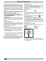
1
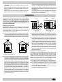
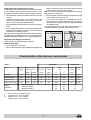
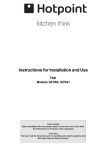
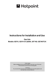
Instructions for Installation and Use
Gas Hob
Model GF760RX
Model GE760RX
To the Installer
Before installation fill in the product details on the back cover of this book.
The information can be found on the rating plate.
To the User
You must read the instructions prior to installing and using the appliance and
then retain them for future reference.
CONTENTS
Introduction
3
Close-up View
4
How To Use Your Appliance
4
How to Keep Your hob in Shape
5
Practical Advice
5
Is there a problem?
6
Safety Is a Good Habit to Get Into
6-7
Installation
7-8-9
Characteristic of the burners and nozzles
9
Electrical Connection
10
After Sales Service
11
Hotpoint Guarantee
12
Key Contacts
Back Cover
Retention of this Instruction Book
This Instruction Book must be kept handy for reference as it contains important details on the safe and proper use of
the appliance.
If you sell or pass the appliance to someone else, or move house and leave it behind, make sure this Book is also
provided so the new owner can become familiar with the appliance and safety warnings.
If the Book is lost or damaged a copy may be obtained from:
INDESIT Company UK LTD, Morley Way, Peterborough, PE2 9JB
2
Introduction
Your new hob is guaranteed* and will give lasting service. This guarantee is only applicable if the appliance has been
installed in accordance with the installation instructions detailed in this booklet.
To help make best use of your cooking equipment, please read this booklet carefully.
The hob is designed specifically for domestic use and responsibility will not be accepted for use in any other installation.
* The guarantee is subject to the provisions that the appliance:
(a) Has been used solely in accordance with this booklet.
(b) Has been properly connected to a suitable supply voltage as stated on the rating plate, attached to the
appliance.
(c) Has not been subjected to misuse or accident or been modified or repaired by any person other than the
manufacturers authorised employee or agent.
(d) Has been correctly installed.
This appliance conforms with the following European Economic Community directives:
- 73/23/EEC of 19/02/73 (Low Voltage) and subsequent modifications;
- 89/336/EEC of 03/05/89 (Electromagnetic Compatibility) and subsequent modifications;
- 90/396/EEC of 29/06/90 (Gas) and subsequent modifications;
- 93/68/EEC of 22/07/93 and subsequent modifications.
- 2002/96/EC
The European Directive 2002/96/EC on Waste Electrical and Electronic Equipment (WEEE), requires that old household
electrical appliances must not be disposed of in the normal unsorted municipal waste stream. Old appliances must
be collected separately in order to optimise the recovery and recycling of the materials they contain and reduce the
impact on human health and the environment. The crossed out “wheeled bin” symbol on the product reminds you of
your obligation, that when you dispose of the appliance it must be separately collected.
Consumers should contact their local authority or retailer for information concerning the correct disposal of their old
appliance.
3
Congratualtions on choosing an Hotpoint appliance, which you will find is dependable and easy to use. We recommend
that you read this manual for best performance and to extend the life of your appliance. Thank you.
Close-up View
F
D
A
A
B
B
C
A
B
C
D
C
Gas Burners
Support Grid for Cookware
Control Knobs for Gas Burners
Ignitor for Gas Burners
F Safety Device - Activates if the flame accidentally goes
out (spills, drafts, etc.), interrupting the delivery of gas
to the burner.
How To Use Your Appliance
To light the selected burner, first press the corresponding
knob down fully, turn it anti-clockwise to the high flame
symbol, and keep the knob pressed down until the burner
ignites for approximately 3-4 seconds to allow the safety
device "F", which keeps the flame lit automatically, to
heat up.
To turn off a burner, turn the knob clockwise until it stops
(it should be on the “•” setting).
Caution: If the burner accidently goes out, turn off the gas
on the control knob and wait at least 1 minute before you
try to to light it again.
The position of the corresponding gas burner or electric
hot plate (if present) is indicated on each control knob.
Gas Burners
The burners differ in size and power. Choose the most
appropriate one for the diameter of the cookware being
used.
The burner can be regulated with the corresonding control
knob by using one of the following settings:
•
Off
High
Low
To turn on one of the burners, place a lighted match or
lighter near the burner, press the knob all the way in and
turn it anti-clockwise to the "High" setting.
On those models fitted with a safety device (F), the
knob must be pressed in for about 4 seconds until the
device that keeps the flame lit warms up.
The section entitled, "Practical Cooking Advice", provides
information on the recommended settings for various types
of food or cooking processes. When the knob is on any of
the settings other than "Off", the operating light comes
on.
4
How to Keep Your Cooktop in Shape
Before cleaning on your appliance, disconnect it from the
electrical power supply.
To extend the life of the hob, it is vital that it be cleaned
carefully and thoroughly on a frequent basis, keeping
in mind the following:
· Do not use steam equipment to clean the appliance.
· Remove any liquid from the lid before opening it.
• The enameled parts and the glass top, if present, must
be washed with warm water without using abrasive
powders or corrosive substances which could ruin them;
• The removable parts of the burners should be washed
frequently with warm water and soap, making sure to
remove caked-on substances;
• On cooktops with automatic ignition, the end of the
electronic ignition device must be cleaned carefully and
frequently, making sure that the gas holes are not
clogged;
•
Stainless steel can be stained if it remains in contact
with highly calcareous water or aggressive detergents
(containing phosphorous) for an extended period of time.
It is recommended that these parts be rinsed thoroughly
with water and then dried well. It is also a good idea to
clean up any spills.
Greasing the Taps
The taps may jam in time or they may become difficult to
turn. If so, the tap itself must be replaced.
N.B.: This operation must be performed by a technician
authorised by the manufacturer.
Practical Advice
Practical Advise on Using the Burners
For best performance, follow these general guidelines:
• Use the appropriate cookware for each burner (see
table) in order to prevent the flame from reaching the
sides of the pot or pan;
• Alwasy use cookware with a flat bottom and keep the
lid on;
• When the contents come to a boil, turn the knob to
"Low".
Burner
ø Cookware diameter (cm)
Fast (R)
24 - 26
Semi Fast (S)
16 - 20
Auxiliary (A)
10 - 14
Triple Crown (TC)
24 - 26
Fishburner (SP)
16 - 20
5
Is there a problem?
It may occur that the hob does not function or does not
function properly. Before calling customer service for
assistance, lets see what can be done.
First of all, check to see that there are no interruptions in
the gas and electrical supplies, and, in particular, that the
gas valves for the mains are open.
The burner does not remain on when set to "Low".
Check to make sure that:
• The gas holes are not clogged.
• There are no draughts near the cooking surface.
• The minimum has been adjusted correctly (see the
section entitled, "Minimum Regulation").
The burner does not light or the flame is not uniform
around the burner.
Check to make sure that:
• The gas holes on the burner are not clogged;
• All of the movable parts that make up the burner are
mounted correctly;
• There are no draughts around the cooking surface.
The cookware is not stable.
Check to make sure that:
• The bottom of the cookware is perfectly flat.
• The cookware is centered correctly on the burner or
electric hot plate.
• The support grids have not been inverted.
If, despite all of these checks, the cooktop does not function
properly and problem persists, call the nearest INDESIT
Company Customer Service Centre, informing them of:
- The type of problem.
- The abbreviation used to identify the model (Mod. ...) as
indicated on the warranty.
Never call upon technicians not authorized by the
manufacturer, and refuse to accept spare parts that are
not genuine.
The flame does not stay lighted on the model with
the safety device.
Check to make sure that:
• You press the knob all the way in;
• You keep the knob pressed in long enough to activate
the safety device.
• The gas holes are not clogged in the area corresponding
to the safety device.
Safety Is a Good Habit to Get Into
To maintain the EFFICIENCY and SAFETY of this appliance, we recommend:
• call only the Service Centers authorized by the manufacturer
• always use original Spare Parts
•
•
•
•
This manual is for a class 3 built-in cooktop.
This appliance is designed for non-professional use in
the home and its features and technical characteristics
must not be modified.
These instructions are only valid for the countries the
symbols for which appear on the manual and the serial
plate.
The electrical system of this appliance is safe only
when it is correctly connected to an adequate earthing
system, as required by current safety standards.
-
Prevent children and the disabled from coming into
contact or having access to the following, as they are
possible sources of danger:
- The controls and the appliance in general;
- The packaging (plastic bags, polystyrene, nails, etc.);
- The appliance, during and immediately after use given
the heat generated by its use;
- The appliance when no longer installed (in this case,
all potentially dangerous parts must be made safe).
Exposure to atmospheric agents (rain, sun);
Using flammable liquids nearby;
Using adaptors, multiple outlet plugs and/or extensions;
Using unstable or deformed cookware;
Leaving the electric hobs on without cookware on top
of them;
Closing the glass top (if present) while the gas burners
or electrical hot plates are still hot;
Trying to install or repair the appliance without the
assistance of qualified personnel.
The assistance of qualified personnel must be called
upon in the following cases:
- Installation (in accordance with the manufacturer's
instructions);
- When in doubt about the operation of the appliance;
- Replacement of the electrical outlet becuase it is
incompatible with the plug.
Contact service centers authorized by the
manufacturer in the following cases:
- When in doubt about the condition of the appliance after
having removed the packing;
- Damage to or replacement of the power supply cord;
- In the case of a breakdown or malfunction: ask for
original spare parts.
The following should be avoided:
- Touching the appliance with wet parts of the body;
- Using the appliance with bare feet;
- Pulling on the appliance or the power supply cord to
disconnect them from the electrical outlet;
- Improper and/or dangerous use;
- Obstructing the ventilation or heat dissipation slots;
- Allowing the power supply cord of small appliances to
come into contact with the hot parts of the cooktop;
It is recommended that you follow the guidelines
below:
- Only use the appliance to cook food, avoiding all other
uses;
6
-
-
-
Check the condition of the appliance after it has been
unpacked;
Disconnect the appliance from the power supply in the
event of malfunction and always before cleaning or
maintenance;
When not in use, disconnect the appliance from the
power supply and turn off the gas valve (if present);
-
•
Always check to make sure that the control knobs are
on the “•”/”o” setting when the appliance is not in use;
Cut the power supply cord after disconnecting it from
the electrical mains when you decide to no longer use
the appliance.
The manufacturer will not be held liable for any damages
arising out of : incorrect installation or improper,
incorrect or unreasonable use..
Installation
The following instructions are directed at the qualified
installer so that the installation and maintenance
proceedures may be followed in the most professional and
expert manner possible. Important: Unplug the electrical
connection before performing any maintenance or
regulation upkeep work.
Detail A
Positioning for gas hob
Important: this unit may be installed and used only in
permanently ventilated rooms according to the British
Stancards Codes Of Practice: B.S. 6172 / B.S. 5440, Par.
2 and B.S. 6891 Current Editions. The following
requirements must be observed:
Room to be
Vented
A
Examples of ventilation holes
for comburant air.
Enlarging the ventilation slot
between window and floor.
Fig. A
Fig. B
c) Intensive and prolonged use of the appliance may necessitate supplemental ventilation, e.g. opening a window or
increasing the power of the air intake system (if present).
a) The room must be fitted with a ventilation system which
vents smoke and gases from combustion to the outside.
This must be done by means of a hood or electric ventilator
that turns on automatically each time the hood is operated.
In a chimney stack or branched flue.
Adjacent
Room
d) Liquidified petroleum gases are heavier than air and, as a
result, settle downwards. Rooms in which LPG tanks are
installed must be fitted with ventilation openings to the
outside in order to allow the gas to escape in the event of
a leak. Therefore, LPG tanks, whether empty or partially
full, must not be installed or stored in rooms or spaces
below ground level (cellars, ect.). It is also a good idea to
keep only the tank currently being used in the room, making
sure that it is not near sources of heat (ovens, fireplaces,
stoves, etc.) that could raise the internal temperature of
the tank above 50°C.
Installation of built-in stove tops
The appliance can be installed next to furniture units which
are no taller than the top of the cooker hob. The wall in
direct contact with the back panel of the cooker must be
made of non-flammable material. During operation the back
panel of the cooker could reach a temperature of 50°C
above room temperature. For proper installation of the
cooker, the following precautions must be taken:
a) The hob may be located in a kitchen, a kitonen/diner or
bed sitting room, but not in a bathroom or shower room.
b) The furniture standing next to the unit, that is higher
than the working boards, must be placed at least 600
mm from the edge of the board.
c) The cabinets should be positioned next to the hood at
a height of at least 420 mm (Fig. C).
Directly to the Outside
(exclusively for cooking appliances)
b) The room must also allow for the influx of the air needed
for proper combustion. The flow of air for combustion
purposes must not be less than 2 m3/h per kW of installed
capacity. The supply of said air can be effected by means
of direct influx from the outside through a duct with a
inner cross section of at least 100 cm² which must not be
able to be accidentally blocked. Those appliances which
are not fitted with a safety device to prevent the flame
from accidentally going out must have a ventilation
opening twice the size otherwise required, i.e. a minimum
of 200cm2 (Fig. A). Otherwise, the room can be vented
indirectly through adjacent rooms fitted with ventilation
ducts to the outside as described above, as long as the
adjacent rooms are not shared areas, bedrooms or present
the risk of fire (Fig. B).
7
540mm min.
700mm min.
600mm min.
g) In the event the hob is not installed above a built-in
oven, a wood panel must be inserted as insulation. This
panel must be placed at least 20 mm from the bottom
of the cooktop itself.
Important: When installing the hob above a built-in oven,
the oven should be placed on two wooden strips; in the
case of a joining cabinet surface, remember to leave a
space of at least 45 x 560 mm at the back.
Fig. C
d) Should the hob be installed directly under a cupboard,
the letter should be at least 700mm (millimetres) from
the worktop, as shown in Fig. C.
e) The dimensions of the room for the furniture must be
those indicated in the figures in the last two pages of
the cover. Fixing hooks are provided which allow to place
the hob plate on work tops that measure from 20 to 40
mm in thickness (see Fig. D). To obtain a good fixing of
the hob plate it is advisable to use all the hooks
supplied.
m.
m
560
m.
Gas connection for gas hob
The cooker should be connected to the gas-supply by a
corgi registered installer. During installation of this product
it is essential to fit an approved gas tap to isolate the
supply from the appliance for the convenience of any
subsequent removal or servicing. Connection of the
appliance to the gas mains or liquid gas must be carried
out according to the prescribed regulation in force, and
only after it is ascertained that it is adaptable to the type
of gas to be used. If not, follow the instructions indicated
in the paragraph headed “Adaptation to different gas types”.
In the case of connection to liquid gas, by tank, use
pressure regulators that conform to the regulation in force.
Important: For safety, for the correct regulation of gas
use and long life of the appliance, ensure that the gas
pressure conforms to the indications given in table 1
“Nozzle and burner characteristics”.
55 mm
475
mm
555 mm
Fig. D
Hook position for
H=30mm top
45 m
Connection to non-flexible tube
(copper or steel)
Connection to the gas source must be done in such a way
as to not create any stress points at any part of the
appliance.
The appliance is fitted with an adjustable, "L" shaped connector
and a gasket for the attachment to the gas supply. Should
this connector have to be turned, the gasket must be replaced
(supplied with the appliance).
The feeding connector of the gas to the appliance is a
threaded 1/2 gas male cylinder.
Hook position for
H=40mm top
Front
Connection to flexible steel tube
The gas feed connector to the appliance is a threaded,
male 1/2" connector for round gas pipe. Only use pipes
and sealing gaskets that conform to the standards currently
in force. The maximum length of the flexible pipes must
not exceed 2000 mm. Once the connection has been made,
ensure that the flexible metal tube does not touch any
moving parts and is not crushed.
Hook position for
Back
H=20mm top
N.B: Use the hook contained in the "accessories set"
f) The hob can only be installed above built-in ovens
provided with cooling ventilation.
Check the Seal
Once the appliance has been installed, make sure all the
connections are properly sealed, using a soapy water solution.
Never use a flame.
8
Adapting the hob for Different Types of Gas
To adapt the hob to a different type of gas than that for which
it was designed, (see the sticker under the hob or on the
packaging), the burner nozzles must be changed, as follows:
• Remove the pan supports and slide the burners out of the
cooktop.
• Unscrew the nozzles using a 7mm socket wrench and
replace them with those for the new type of gas. (See
table 1, “Burner and Nozzle Specifications”).
• Reassemble the parts following the instructions in reverse
order.
• On completing the operation, replace the old rating label
with the one showing the new type of gas; the sticker is
available from our Service Centre.
If the gas pressure is different than that prescribed, a pressure
regulator must be installed at the source, in compliance with
national standards governing the use of piped gas regulators.
either on the side of the top or inside the shaft) clockwise
until the flame becomes small but regular.
N.B.: In the case of liquid gas, the regulation screw must be
fully screwed in (clockwise).
• Make sure that, when the knob is turned rapidly from high
to low, the flame does not go out.
• In the event of a malfunction on appliances with the
security device (thermocouple) when the gas supply is
set at minimum, increase the minimum supply levels using
the regulator screw.
Once the adjustment has been made, apply sealing wax, or
a suitable substitute, to the old seals on the by-pass.
Regulation of Air Supply to the Burner
The burners do not need a primary air regulator.
Minimum Regulation
• Turn the gas valve to minimum.
• Remove the knob and turn the regulator screw (positioned
Characteristic of the burners and nozzles
Table 1
Burner
Liquid Gas
Diameter
(mm)
Thermal power
kW (p.c.s.*)
By-Pass
1/100
Nozzle
1/100
Natural Gas
Flow*
g/h
Nozzle
1/100
Nomin.
Ridot.
(mm)
(mm)
***
**
(mm)
Flow*
l/h
Fast (R)
100
3,00
0,70
41
86
218
214
116
286
Semi Fast (S)
75
1,90
0,40
30
70
138
136
106
181
Auxiliary (A)
55
1,00
0,40
30
50
73
71
79
95
Triple Crown (TC)
100
2,50
0,80
48
83
182
179
124
238
28-30
20
35
37
25
45
Supply
Pressures
*
**
***
Nominal (mbar)
Minimum (mbar)
Maximum (mbar)
At 15°C and 1013 mbar-dry gas
Propane P.C.S. = 50.37 MJ/kg.
Butane P.C.S. = 49.47 MJ/kg.
Natural P.C.S. = 37.78 MJ/m3
9
20
17
25
Electrical Connection
Power supply voltage and frequency: 230-240V a.c.50 Hz.
Note: the supply cable must be positioned so that it never reaches
at any point a temperature 50°C higher than the room temperature.
The cable must be routed away from the rear vents. Should you
require it, you may use a longer cable, however, you must ensure
that the cable supplied with the appliance is replaced by one of the
same specifications in accordance with current standards and
legislation.
Your appliance is supplied with a 13 amp fused plug that can be
plugged into a 13 amp socket for immediate use. Before using the
appliance please read the instructions below.
WARNING -THIS APPLIANCE MUST BE EARTHED.
THE FOLLOWING OPERATIONS SHOULD BE CARRIED OUT
BY A QUALIFIED ELECTRICIAN.
Disposing of the plug:
Ensure that before disposing of the plug itself, you make the pins
unusable so that it cannot be accidentally inserted into a socket.
Instructions for connecting cable to an alternative plug:
Important: the wires in the mains lead are coloured in accordance
with the following code:
Green &Yellow
- Earth
Blue
- Neutral
Brown
- Live
If the colours of the wires in the mains lead do not correspond with
the coloured markings identifying the terminals in your plug, proceed
as follows:
Connect Green &Yellow wire to terminal marked“E”or or coloured
Green or Green &Yellow.
Connect Brown wire to terminal marked “L” or coloured Red.
Connect Blue wire to terminal marked “N” or coloured Black.
If a 13 amp plug (BS 1363) is used it must be fitted with a 13 amp
fuse. A 15 amp plug must be protected by a 15 amp fuse, either in
the plug or adaptor or at the distribution board. If you are in any doubt
about the electrical supply to your machine, consult a qualified
electrician before use.
Replacing the fuse:
When replacing a faulty fuse, a 13 amp ASTA approved fuse to BS
1362 should always be used, and the fuse cover re-fitted. If the fuse
cover is lost, the plug must not be used until a replacement is
obtained.
Replacement fuse covers:
If a replacement fuse cover is fitted, it must be of the correct colour
as indicated by the coloured marking or the colour that is embossed
in words on the base of the plug. Replacements can be obtained
directly from your nearest Service Depot.
How to connect an alternative plug:
The wires in this mains lead are coloured in accordance with the
following code:
BLUE
“NEUTRAL”(“N”)
BROWN
“LIVE”(“L”)
GREEN ANDYELLOW
“EARTH” (“E”)
Removing the plug:
If your appliance has a non-rewireable moulded plug and you should
wish to remove it to add a cable extension or to re-route the mains
cable through partitions, units etc., please ensure that either:
• the plug is replaced by a fused 13 amp re-wireable plug bearing
the BSI mark of approval.
or:
• the mains cable is wired directly into a 13 amp cable outlet,
controlled by a switch, (in compliance with BS 5733) which is
accessible without moving the appliance.
Please note: for appliances with a rating greater than 13 amp (eg:
electric hob, double ovens and freestanding electric cookers etc.)
the mains cable must be wired into a cooker output point with a
rating of 45 amp. In this case the cable is not supplied.
GREEN &
YELLOW
BROWN
BLUE
13 amp fuse
CROSS-BAR
CORD GRIP
Disposing of the appliance
When disposing of the appliance please remove the plug by cutting
the mains cable as close as possible to the plug body and dispose
of it as described above.
10
After Sales Service
"No company is better positioned to offer an after sales service on a
Hotpoint appliance than us - the manufacturer"
As part of our commitment to you, all Hotpoint appliances have the added benefit of a fully inclusive parts
and labour guarantee for the first 12 months. In addition to this you also have the advantage of free
replacement parts for the first 5 years when fitted by a Hotpoint
engineer. When the 12 months parts and labour guarantee expires we offer the following after sales
service options:
Repair Service and Information Help Desk
UK: 08709 066066
www.hotpointservice.co.uk
Republic of Ireland: 1850 302 200
Note: Our operators will require the Model number and the Serial number of your appliance
Available 364 days a year with a fast, effective and value for money service. We have the largest white
goods repair service in the UK with over 1200 of our own fully trained engineers. All repairs include a
parts and labour guarantee for 12 months from the date of the repair.
If you require any information or have any questions about your appliance, our operators are on hand with
help and advice.
All this ensures that you will receive the best available after sales service possible.
Extended Warranties
UK: 08709 088 088
www.hotpointservice.co.uk
Republic of Ireland: 1850 502 200
Whether you have just one or a number of Hotpoint appliances in your kitchen, we offer two service cover
plans to give you total peace of mind.
l Repair Protection Plan
FREE service repairs for a single Hotpoint appliance during the period
of cover.
l Kitchen Cover
FREE service repairs for all your Hotpoint appliances less than 8
years old.
Genuine Parts and AccessoriesUK: 08709 077 077
www.hotpointservice.co.uk
Republic of Ireland: (01) 842 6836
A wide range of genuine parts and accessories are available from our hotline or through our web site.
Genuine parts and accessories, extended warranties and service repairs are all
available on our web-site at:
www.hotpointservice.co.uk
GB
11
Guarantee
"Satisfaction guaranteed or your money back"
We give you a unique 'satisfaction guaranteed' promise - valid for 90 days - after you have
purchased your Hotpoint appliance. If there is a technical problem simply call our Hotpoint Repair
Service or visit our web-site at www.hotpointservice.co.uk and where necessary, we will arrange for an
engineer to call. If the technical problem is not resolved under this guarantee, we will replace your
machine or, if you prefer, give you your money back.
All Hotpoint appliances carry a fully inclusive 12 month parts and labour guarantee as well as free
replacement parts for the first 5 years provided that they are fitted by a Hotpoint engineer.
Guarantee terms and conditions
Your guarantee is only applicable in the United Kingdom or Republic of Ireland and is subject to the
following provisions that your appliance:
l
Has been installed and used correctly in accordance with this instruction booklet.
l
Has been used solely for domestic purposes and is located on domestic premises (ie. not for
commercial or trade use).
l
Has been properly connected to a suitable electrical supply voltage as stated on the appliance
rating plate.
l
Has not been subject to misuse, accident, modified or repaired by anyone other than one of our
own service engineers.
For pre purchase information on any other Hotpoint product call: 08701 50 60 70
or visit: www.hotpoint.co.uk
Recycling & Disposal Information
As part of Hotpoint's continued commitment to helping the environment, Hotpoint reserves the right to
use quality recycled components to keep down customer costs and minimise material wastage.
Please dispose of packaging and old appliances carefully.
To minimise risk of injury to children, remove the door, plug and cut mains cable off flush with the
appliance. Dispose of these parts separately to ensure that the appliance can no longer be plugged
into a mains socket, and the door cannot be locked shut.
12
GB
13
14
15
Key Contacts
After Sales Service
Over 1200 trained specialists, directly employed by us, ensure that you can have complete confidence in
both the appliances and services we offer.
Repair Service and Information Desk
UK: 08709 066 066
(Open 8 to 8 Mon - Fri, 8 to 6 Sat, 10 to 4 Sun & Bank Holidays)
www.theservicecentre.co.uk
Republic of Ireland: 1850 302 200
Note: Our operators will require the following information:
Model number:
Serial number:
Extended Warranties
UK: 08709 088 088
(Open 8 to 8 Mon - Sun)
www.theservicecentre.co.uk
Republic of Ireland: 1850 502 200
Genuine Parts and Accessories
UK: 08709 077 077
(Open 8-30 to 5-30 Mon - Fri & 9 to 12 Sat)
www.theservicecentre.co.uk
Republic of Ireland: (01) 842 6836
Indesit Company UK Ltd. Morley Way, Peterborough, PE2 9JB.
10/2005 - 195043661.02