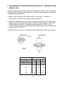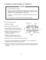
1
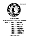
NO.: 73095 ISSUED: FEB. 4, 1998 REVISED: NOV. 29, 2000 HOSHIZAKI MODULAR CRESCENT CUBER MODEL KML-200MAE KML-200MWE SERVICE MANUAL FOREWORD IMPORTANT Only qualified service technicians should attempt to service or maintain this icemaker. No such service or maintenance should be undertaken until the technician has thoroughly read this Service Manual. HOSHIZAKI provides this manual primarily to assist qualified service technicians in the service and maintenance of the icemaker. Should the reader have any questions or concerns which have not been satisfactorily addressed, please call or write to the HOSHIZAKI Care Department for assistance. HOSHIZAKI AMERICA, INC. 618 Highway 74 South Peachtree City, GA 30269 Attn: HOSHIZAKI Care Department Phone: 1-800-233-1940 Technical Service (770) 487-2331 Fax: (770) 487-3360 NOTE: To expedite assistance, all correspondence/communication MUST include the following information: • Model Number • Serial Number • Complete and detailed explanation of the problem 2 Please review this manual. It should be read carefully before the icemaker is serviced or maintenance operations performed. Only qualified service technicians should service and maintain the icemaker. This manual should be made available to the technician prior to service or maintenance. CONTENTS PAGE I. SPECIFICATIONS .................................................................................................... 5 1. KML-200MAE (Air-cooled) .................................................................................. 5 2. KML-200MWE (Water-cooled) ............................................................................. 6 II. GENERAL INFORMATION ...................................................................................... 7 1. CONSTRUCTION ............................................................................................... 7 [a] KML-200MAE (Air-cooled) ............................................................................ 7 [b] KML-200MWE (Water-cooled) ....................................................................... 8 2. CONTROLLER BOARD ...................................................................................... 9 [a] SOLID-STATE CONTROL ............................................................................ 9 [b] CONTROLLER BOARD ................................................................................ 9 [c] SEQUENCE ................................................................................................ 12 [d] CONTROLS AND ADJUSTMENTS ........................................................... 15 [e] CHECKING CONTROLLER BOARD ......................................................... 18 3. SWITCHES ....................................................................................................... 20 III. TECHNICAL INFORMATION ............................................................................... 21 1. WATER CIRCUIT AND REFRIGERANT CIRCUIT .......................................... 21 [a] KML-200MAE (Air-cooled) .......................................................................... 21 [b] KML-200MWE (Water-cooled) ..................................................................... 22 2. WIRING DIAGRAMS ......................................................................................... 23 [a] KML-200MAE (Air-cooled) .......................................................................... 23 [b] KML-200MWE (Water-cooled) ..................................................................... 23 3. TIMING CHART ................................................................................................ 24 4. PERFORMANCE DATA ................................................................................... 26 [a] KML-200MAE (Air-cooled) .......................................................................... 26 [b] KML-200MWE (Water-cooled) ..................................................................... 27 IV. SERVICE DIAGNOSIS ........................................................................................ 28 1. NO ICE PRODUCTION ..................................................................................... 28 2. EVAPORATOR IS FROZEN UP ....................................................................... 31 3. LOW ICE PRODUCTION .................................................................................. 31 4. ABNORMAL ICE ............................................................................................... 32 5. OTHERS ........................................................................................................... 32 3 V. REMOVAL AND REPLACEMENT OF COMPONENTS.......................................... 33 1. SERVICE FOR REFRIGERANT LINES .............................................................. 33 [a] REFRIGERANT RECOVERY ........................................................................ 33 [b] EVACUATION AND RECHARGE ................................................................. 33 2. BRAZING ............................................................................................................. 34 3. REMOVAL AND REPLACEMENT OF COMPRESSOR...................................... 34 4. REMOVAL AND REPLACEMENT OF DRIER .................................................... 36 5. REMOVAL AND REPLACEMENT OF EXPANSION VALVE .............................. 36 6. REMOVAL AND REPLACEMENT OF HOT GAS VALVE AND .............................. LINE VALVE ........................................................................................................ 37 7. REMOVAL AND REPLACEMENT OF EVAPORATOR ...................................... 39 8. REMOVAL AND REPLACEMENT OF WATER-REGULATING VALVE ................. - WATER COOLED MODEL ONLY .................................................................... 40 9. ADJUSTMENT OF WATER-REGULATING VALVE ............................................... - WATER COOLED MODEL ONLY .................................................................... 41 10. REMOVAL AND REPLACEMENT OF THERMISTOR ........................................ 42 11. REMOVAL AND REPLACEMENT OF FAN MOTOR ........................................... 43 12. REMOVAL AND REPLACEMENT OF WATER VALVE ...................................... 44 13. REMOVAL AND REPLACEMENT OF PUMP MOTOR ........................................ 44 14. REMOVAL AND REPLACEMENT OF SPRAY TUBE ......................................... 45 VI. CLEANING AND MAINTENANCE INSTRUCTIONS ............................................. 46 1. PREPARING THE ICEMAKER FOR LONG STORAGE...................................... 46 2. CLEANING ........................................................................................................... 48 3. SANITIZING ......................................................................................................... 50 4. MAINTENANCE ................................................................................................... 51 4 I. SPECIFICATIONS 1. KML-200MAE AC SUPPLY VOLTAGE AMPERAGE MINIMUM CIRCUIT AMPACITY MAXIMUM FUSE SIZE APPROX. ICE PRODUCTION PER 24 HR. lbs./day ( kg./day ) Reference without *marks 115/60/1 10.8 A (5 Min. Freeze AT 104° F / WT 80° F) 20A 20A Ambient Water Temp. (°F) Temp. (°F) 50 70 90 70 *250 (113) 240 (109) 220 (100) 80 241 (109) 226 (103) 210 ( 95) 90 230 (104) *214 ( 97) 199 ( 90) 100 218 ( 99) 203 ( 92) 187 ( 85) SHAPE OF ICE ICE PRODUCTION PER CYCLE APPROXIMATE STORAGE CAPACITY ELECTRIC & WATER CONSUMPTION ELECTRIC W ( KWH/100 lbs. ) WATER gal./24 HR. ( gal./100 lbs. ) EXTERIOR DIMENSIONS ( WxDxH ) EXTERIOR FINISH WEIGHT CONNECTIONS - ELECTRIC - WATER SUPPLY - DRAIN Crescent Cube 3.9 lbs. (1.8 kg) 180 pcs. N/A 90°F/70°F 70°F/50°F 820 (9.2) 760 (6.7) 64 (29.9) 81 (30.8) 30"x27-3/8"x22" (762x695x560 mm) Stainless Steel, Galvanized Steel (Rear) Net 150 lbs. (68 kg) Permanent Connection Inlet 1/2" FPT Outlet 3/4" FPT CUBE CONTROL SYSTEM HARVESTING CONTROL SYSTEM ICE MAKING WATER CONTROL COOLING WATER CONTROL BIN CONTROL SYSTEM COMPRESSOR CONDENSER EVAPORATOR REFRIGERANT CONTROL REFRIGERANT CHARGE DESIGN PRESSURE P.C. BOARD CIRCUIT PROTECTION COMPRESSOR PROTECTION REFRIGERANT CIRCUIT PROTECTION LOW WATER PROTECTION ACCESSORIES - SUPPLIED - REQUIRED OPERATION CONDITIONS Float Switch Hot gas and water, thermistor and timer Timer controlled, Overflow pipe N/A Thermostat Hermetic, Model RSU4-0050-CAA Air-cooled, fin and tube type Vertical type, Stainless Steel and Copper Thermostatic Expansion Valve R22, 1lb. (465g) High 427 PSIG, Low 206 PSIG High Voltage Cut-out (Internal) Auto-reset Overload Protector (Internal) Auto-reset High Pressure Control Switch Float Switch N/A Ice Storage Bin VOLTAGE RANGE 104 - 127 V AMBIENT TEMP. 45 - 100°F WATER SUPPLY TEMP. 45 - 90°F WATER SUPPLY PRESS. 10 - 113PSIG * We reserve the right to make changes in specifications and design without prior notice. 5 2. KML-200MWE AC SUPPLY VOLTAGE AMPERAGE MINIMUM CIRCUIT AMPACITY MAXIMUM FUSE SIZE APPROX. ICE PRODUCTION PER 24 HR. lbs./day ( kg./day ) Reference without *marks 115/60/1 8.3 A ( 5 Min. Freeze AT 104° F / WT 80° F ) 20A 20A SHAPE OF ICE ICE PRODUCTION PER CYCLE APPROXIMATE STORAGE CAPACITY ELECTRIC & WATER CONSUMPTION ELECTRIC W ( KWH/100 lbs. ) WATER gal./24 HR. ( gal./100 lbs. ) WATER COOLED CONDENSER gal./24 hr. ( gal./100 lbs. ) EXTERIOR DIMENSIONS ( WxDxH ) EXTERIOR FINISH WEIGHT CONNECTIONS - ELECTRIC - WATER SUPPLY - DRAIN CUBE CONTROL SYSTEM HARVESTING CONTROL SYSTEM ICE MAKING WATER CONTROL COOLING WATER CONTROL BIN CONTROL SYSTEM COMPRESSOR CONDENSER EVAPORATOR REFRIGERANT CONTROL REFRIGERANT CHARGE DESIGN PRESSURE P.C. BOARD CIRCUIT PROTECTION COMPRESSOR PROTECTION REFRIGERANT CIRCUIT PROTECTION LOW WATER PROTECTION ACCESSORIES - SUPPLIED - REQUIRED OPERATION CONDITIONS Crescent Cube 3.9 lbs. ( 1.8 kg. ) 180 pcs. N/A 90° F / 70° F 70° F / 50° F 713 ( 8.6 ) 700 ( 7.0 ) 72 ( 36.3 ) 88 ( 36.8 ) 330 ( 166 ) 138 ( 57.6 ) Ambient Water Temp. (°F) Temp. (°F) 50 70 90 190 (86) 70 *238 (108) 220 (100) 80 232 (105) 208 ( 94) 184 (83) 90 223 (101) *199 ( 90) 175 (79) 215 ( 98) 190 ( 86) *167 (76) 100 30" x 273¦8" x 22" ( 762 x 695 x 560 mm. ) Stainless steel, Galvanized Steel ( Rear ) Net 150 lbs. ( 60 kg. ) Permanent Connection 1 2 Inlet ¦ " FPT Condenser Inlet 1¦2" FPT 3 4 ¦ " FPT Condenser Outlet 3¦8" FPT Outlet Float Switch Hot Gas and Water, Thermistor and Timer Timer Controlled, Overflow Pipe Pressure Regulator Thermostat Hermetic, Model RSU4-0050-CAA Water-cooled, Tube in Tube type Vertical type, Stainless Steel and Copper Thermostatic ExpansionValve R22, 10 oz. ( 290 g. ) High 395 PSIG, Low 206 PSIG High Voltage Cut-out Relay ( Internal ) Auto-reset Overload Protector ( Internal ) Auto-reset High Pressure Control Switch Float Switch N/A Ice Storage Bin VOLTAGE RANGE 104 - 127 V AMBIENT TEMP. 45 - 100° F WATER SUPPLY TEMP. 45 - 90° F WATER SUPPLY PRESS. 10 - 113 PSIG * We reserve the right to make changes in specifications and design without prior notice. 6 II. GENERAL INFORMATION 1. CONSTRUCTION [a] KML-200MAE 7 [b] KML-200MWE 8 2. CONTROLLER BOARD [a] SOLID-STATE CONTROL 1) A HOSHIZAKI exclusive solid-state control is employed in KML-200 Series Modular Crescent Cubers. 2) A Printed Circuit Board (hereafter called “Controller Board”) includes a stable and high quality control system. 3) All models are pre-tested and factory-adjusted. [b] CONTROLLER BOARD CAUTION 1. Fragile, handle very carefully. 2. A controller board contains integrated circuits, which are susceptible to failure due to static discharge. It is especially important to touch the metal part of the unit when handling or replacing the board. 3. Do not touch the electronic devices on the board or the back of the board to prevent damage to the board. 4. Do not change wiring and connections. Especially, never misconnect K3, K4 and K5, because the same connector is used for the Thermistor and Float Switch. K4 is not connected. 5. Do not fix the electronic devices or parts on the board in the field. Always replace the whole board assembly when it goes bad. 6. Do not short out power supply to test for voltage. PART NUMBER TYPE 2U0127-01 MY9KM910 (Alpine) Note: (1) Maximum Water Supply Period - 6 minutes Water Solenoid Valve opening, in the Defrost (Harvest) Cycle, is limited by maximum period of the defrost timer. The Water Valve cannot remain open longer than the maximum period. The Water Valve can close in less than the maximum period if the defrost cycle is completed. 9 (2) Defrost Timer The defrost cycle starts when the Float Switch opens and completes the freeze cycle. But the Defrost Timer does not start counting until the Thermistor senses 48°F at the Evaporator outlet. The period from the end of the freeze cycle up to the point of the Thermistor's sensing varies depending on the ambient and water temperatures. (3) High Temperature Safety - 127 ± 7°F The temperature of the suction line in the refrigerant circuit is limited by the High Temperature Safety. During the defrost cycle the Evaporator temperature rises. The Thermistor senses 48°F and starts the Defrost Timer. After the Defrost Timer counts down to zero, the normal freeze cycle begins. If the Evaporator temperature continues to rise, the Thermistor will sense the rise in temperature and at 127 ± 7°F the Thermistor operates the High Temperature Safety. This High Temperature Safety shuts down the circuit and the icemaker automatically stops. To reset the safety, turn the power off and back on again. This High Temperature Safety protects the unit from excessive temperature. (4) Low Water Safety The Controller Board checks the position of the Float Switch at the end of the initial one minute water fill cycle and at the end of each defrost cycle. If the Float Switch is in the up position (electrical circuit closed), the Controller Board changes to the ice making cycle. If the Float Switch is in the down position (electrical circuit open), the Controller Board changes to a one minute water fill cycle before starting the ice making cycle. For water-cooled model, if the water is shut off, the unit is protected by the High Pressure Switch. (5) High Voltage Cut-out The maximum allowable supply voltage of this icemaker is limited by the High Voltage Cut-out. If miswiring causes excessive voltage on the Controller Board, the High Voltage Cut-out shuts down the circuit in 3 seconds and the icemaker automatically stops. When the proper supply voltage is resumed, the icemaker automatically starts running again. 10 Connector K1 Pin #1 thru #10 #1, 9 #2 #3 #4 #5 #6 #7, 10 #8 Magnetic Contactor Hot Gas Valve Line Valve Pump Motor (icemaking) Pump Motor (drain) Water Valve Power (line, Bin Control) Open Dip Switch Defrost Timer, Drain Timer & Drain Counter Connector K5 Float Switch Connector K4 Open (not connected) Connector K3 Defrost Control (Thermistor) (Alpine “C”/Alpine Board) 11 [c] SEQUENCE 1st Cycle 1. Unit energized and Control Switch to “ICE” position. Water supply cycle starts. 3. Thermistor reads 48° F. Defrost Timer (adjustable from 1 to 3 minutes) starts counting. 2. After 1 minute, Defrost cycle starts. IMPORTANT Water Valve opening is limited to 6 minutes. 4. Defrost Timer stops counting. Defrost cycle is completed and freeze cycle starts. 5. After the first 5 minutes in freeze cycle. Ready to complete freeze cycle when Float Switch circuit opens. IMPORTANT Board never accepts freeze completion signal within the first 5 minutes in freeze cycle. IMPORTANT 1. Board never accepts defrost completion signal within the first 2 minutes in defrost cycle. 2. Defrost cycle time is limited to 20 minutes even if Defrost Timer does not stop counting. 12 2nd Cycle and after with pump drain IMPORTANT Freeze cycle time is limited to 60 minutes even if Float Switch does not open. 2. Drain Timer stops counting. Pump drain is completed 1. Float Switch opens and signals to complete freeze cycle. 10/20 second Drain Timer starts counting. 3. Thermistor reads 48° F. Defrost Timer (adjustable from 1 to 3 minutes) starts counting. IMPORTANT Water Valve opening is limited to 6 minutes. , & LINE VALVE 5. After the first 5 minutes in freeze cycle. Ready to complete freeze cycle when Float Switch circuit opens. 4. Defrost Timer stops counting. Defrost cycle is completed and freeze cycle starts. IMPORTANT Board never accepts freeze completion signal within the first 5 minutes in freeze cycle. IMPORTANT 1. Board never accepts defrost completion signal within the first 2 minutes in defrost cycle. 2. Defrost cycle time is limited to 20 minutes even if Defrost Timer does not stop counting. 13 2nd Cycle and after with no pump drain IMPORTANT Freeze cycle time is limited to 60 minutes even if Float Switch does not open. 2. Thermistor reads 48° F. Defrost Timer (adjustable from 1 to 3 minutes) starts counting. 1. Float Switch opens and signals to complete freeze cycle. IMPORTANT Water Valve opening is limited to 6 minutes. 3. Defrost Timer stops counting. Defrost cycle is completed and freeze cycle starts. 4. After the first 5 minutes in freeze cycle. Ready to complete freeze cycle when Float Switch circuit opens. IMPORTANT Board never accepts freeze completion signal within the first 5 minutes in freeze cycle. IMPORTANT 1. Board never accepts defrost completion signal within the first 2 minutes in defrost cycle. 2. Defrost cycle time is limited to 20 minutes even if Defrost Timer does not stop counting. 14 [d] CONTROLS AND ADJUSTMENTS (Alpine/Alpine “C” Board) The Dip Switch is factory-adjusted to the following positions: DIP SWITCH NO. KML-200MAE, KML-200MWE 1 2 3 4 5 6 7 8 OFF OFF OFF ON OFF OFF ON ON ON ON ON ON OFF OFF OFF OFF Switch Nos. 1 and 2: Used for adjustment of the Defrost Timer. The Defrost Timer starts counting when the Thermistor reads a certain temperature at the Evaporator outlet. Switch Nos. 3 and 4: Used for adjustment of the Drain Timer. When a freeze cycle is completed, the Pump Motor stops, and the icemaker resumes operation in 2 seconds. Then the Pump Motor drains the Water Tank for the time determined by the Drain Timer. The Drain Timer also determines the time to restrain completion of a defrost cycle, i.e. the minimum defrost time. Switch Nos. 5 and 6: Used for adjustment of the Drain Counter. The Pump Motor drains the Water Tank at the frequency determined by the Drain Counter. Switch Nos. 7 and 8: Used only for checking the Controller Board. Usually set in OFF position. 15 1) Defrost Control A thermistor (Semiconductor) is used for a defrost control sensor. The resistance varies depending on the Suction Line temperatures. The Thermistor detects the temperature of the Evaporator outlet to start the Defrost Timer. No adjustment is required. If necessary, check for resistance between Thermistor leads, and visually check the Thermistor mounting, located on the Suction Line next to the Evaporator outlet. Temperature (°F) 0 10 32 50 70 90 Resistance (kW) 14.401 10.613 6.000 3.871 2.474 1.633 Check a thermistor for resistance by using the following procedures. (i) Disconnect the connector K3 on the board. (ii) Remove the Thermistor. See “V. 11. REMOVAL AND REPLACEMENT OF THERMISTOR.” (iii) Immerse the Thermistor sensor portion in a glass containing ice and water for 2 or 3 minutes. (iv) Check for a resistance between Thermistor leads. Normal reading is within 3.5 to 7kW. Replace the Thermistor if it exceeds the normal reading. 2) Defrost Timer No adjustment is required under normal use, as the Defrost Timer is adjusted to the suitable position. However, if necessary when all the ice formed on the Evaporator does not fall into the bin in the harvest cycle, adjust the Defrost Timer to longer position by setting the Dip Switch (No. 1 & 2) on the Controller Board. SETTING Dip Switch Dip Switch No. 1 No. 2 OFF ON OFF ON OFF OFF ON ON TIME 60 seconds 90 seconds 120 seconds 180 seconds 16 3) Drain Timer The Drain Timer is factory-adjusted, and no adjustment is required. SETTING Dip Switch Dip Switch No. 3 No. 4 OFF ON OFF ON TIME OFF OFF ON ON T1 T2 10 seconds 10 seconds 10 seconds 20 seconds 150 seconds 180 seconds 120 seconds 180 seconds T1: Time to drain the Water Tank T2: Time to restrain defrost completion 4) Drain Counter CAUTION Do not adjust the Drain Counter, or the Evaporator may freeze up. Except for some B-type models, the Drain Counter is factory-adjusted to drain the Water Tank every 10 cycles, and no adjustment is required. However, where water quality is bad and the icemaker needs a pump drain more often, the Drain Counter can be adjusted as shown in the table below: SETTING Dip Switch Dip Switch No. 5 No. 6 OFF ON OFF ON FREQUENCY OFF OFF ON ON every cycle every 2 cycles every 5 cycles every 10 cycles 17 5) Bin Control CAUTION When the ambient temperature is below 45°F, the Bin Control Thermostat operates to stop the icemaker even if the Ice Storage Bin is empty. When the Thermostat is set in the prohibited range, the icemaker operates continuously even if the Ice Storage Bin is filled with ice. Setting in the prohibited range might cause severe damage to the icemaker resulting in failure. No adjustment is required under normal use, as the Bin Control is factory-adjusted. Adjust it, if necessary, so that the icemaker stops automatically in approximately 6 to 10 seconds after ice contacts the Bin Control Thermostat Bulb. [e] CHECKING CONTROLLER BOARD 1) Visually check the sequence with the icemaker operating. 2) Visually check the Controller Board by using the following procedures. (i) Adjust the Defrost Timer to minimum position. Disconnect the Thermistor from the Controller Board. Connect a 1.5kW - 3.5kW resistor to the Connector K3 (pins #1 and #2), and energize the unit. After the 1 minute ± 5 second water supply cycle and the 2 minute ± 10 second defrost cycle, the unit should start the freeze cycle. (ii) After the above step (i), disconnect the Float Switch leads from the Controller Board within the first 5 minutes of the freeze cycle. The unit should go into the defrost cycle after the first 5 minutes ± 20 seconds of the freeze cycle. (iii) Reconnect the Float Switch Connector to the Controller Board. After the first 5 minutes of the freeze cycle, disconnect the Float Switch leads from the Controller Board. At this point, the unit should start the defrost cycle. (iv) After Step (iii), de-energize the unit and confirm that the Defrost Timer is in the minimum position. Disconnect the resistor from the Controller Board, and energize the unit. After the 1 minute water supply cycle, the defrost cycle starts. Re-connect a 1.5kW - 3.5kW resistor to the Connector K3 (pins #1 and #2) after the first 2 minutes of the defrost cycle. 18 The unit should start the freeze cycle after 1 minute ± 5 seconds from the resistor connection. 3) Check the Controller Board by using test program of the Controller Board. (i) Disconnect the Connector K1 from the Controller Board. Set the Dip Switch No. 7 and 8 on the Controller Board to the “ON” position, and energize the unit. (ii) The current flows to each Relay (from X1 to X4) one after another every time the float is raised and the contacts close. See the following chart, and check “OPEN” and “CLOSE” of Pins of the Connector K1 at each step. (iii) If the checks are completed, turn off the icemaker, plug the Connector K1 into the Controller Board as before, and set the Dip Switch No. 7 and 8 to the “OFF” position. TEST PROGRAM OF CONTROLLER BOARD 19 3. SWITCHES Two control switches are used to control operation in the KML Series Modular Crescent Cubers. These switches are referred to as the “Control Switch” and the “Service Switch.” [a] CONTROL SWITCH The Control Switch is located on the lower left section of the control box when facing the front of the machine. This switch is used to place the machine into one of three modes: “Power Off” (Center position), “Ice Making” (Right position), and “Service” (Left position). [b] SERVICE SWITCH When the Control Switch is pushed to the left, the machine is placed in “Service” mode. In this position the Control Switch supplies power to the Service Switch. The Service Switch can be used to perform three funtions: Drain the tank (left position), Circulate water (center position), Wash the ice making compartment (right position). When the Service Switch is activated power is supplied to the pump in all three positions. 1) Drain The KML series utilizes a pump-out drain system. When the Service Switch is active and placed in the left position, power is supplied to the pump and the Drain solenoid valve. 2) Wash The KML series utilizes a solenoid operated cleaning valve. When the Service Switch is active and placed in the right position, power is supplied to the pump and the Bypass solenoid valve. This cleans both the inside and outside of the evaporator plate assembly. 3) Circulate When the Service switch is active and placed in the center position, power is supplied to the pump only. This operation can be used to circulate cleaner for extended periods of time over the outside surface of the Evaporator. 20 III. TECHNICAL INFORMATION 1. WATER CIRCUIT AND REFRIGERANT CIRCUIT [a] KML-200MAE 21 [b] KML-200MWE 22 Note: KML-200MAE Pressure Switch 2. WIRING DIAGRAMS Cut-out 384 ± 21.3 PSIG Cut-in 284.5 ± 21.3 PSIG [a] KML-200MAE, KML-200MWE KML-200MWE Pressure Switch Cut-out 355.6 ± 21.3 PSIG Cut-in 256 ± 21.3 PSIG 23 3. TIMING CHART When Control Sw. is turned OFF, Pressure Sw. is OFF, or Thermistor Temp. exceeds t1. From Defrost Cycle To Defrost Cycle If Float Sw. is OFF Hi Temp Mid Temp Lo Temp Too Lo Temp Normal Too Hi Temp Lo Water Time Up (60 sec) Control Sw. in ICE Bin Thermostat ON Max. 60 min Pressure Sw. ON Min. 5 min Overheat Protect Reset * Min. 2 min * Max. 6 min Max. 6 min Max. 20 min *3 (KM-1200MAE/SAE) *4 (KM-1200MRE/SRE, KM-2000SRE3) *NOTE: The icemaker does not complete a defrost cycle in the first 2 or 3 minutes. See “II. 2. [d] CONTROLS AND ADJUSTMENTS.” 24 To Stand-by Cycle (When Control Sw. is turned OFF, Pressure Sw. is OFF, or Thermistor Temp. exceeds t1.) To Freeze Cycle From Freeze Cycle Control Sw. in WASH *1 *2 Min. 3 min Max. 6 min *2 Max. 6 min Max. 20 min *3 (KM-1200MAE/SAE) *4 (KM-1200MRE/SRE, KM-2000SRE3) *1 The Pump Motor waits for 2 seconds before starting a drain cycle. See “II. 2. [d] CONTROLS AND ADJUSTMENTS.” *2 The icemaker does not complete a defrost cycle in the first 2 or 3 minutes. See “II. 2. [d] CONTROLS AND ADJUSTMENTS.” 25 4. PERFORMANCE DATA [a] KML-200MAE APPROXIMATE ICE PRODUCTION PER 24 HR. lbs./day (kg./day) APPROXIMATE ELECTRIC CONSUMPTION watts APPROXIMATE WATER CONSUMPTION PER 24 HR. gal./day (m3/day) FREEZING CYCLE TIME min. HARVEST CYCLE TIME min. HEAD PRESSURE PSIG SUCTION PRESSURE PSIG (kg/cm2G) TOTAL HEAT OF REJECTION AMBIENT TEMP. ( °F/°C ) 50/10 70/21 80/27 90/32 100/38 *250 (113) 241 (109) 230 (104) 218 ( 99) 70/21 80/27 90/32 100/38 *770 774 776 787 70/21 80/27 90/32 100/38 *81 ( 0.31 ) 75 ( 0.28 ) 73 ( 0.28 ) 71 ( 0.27 ) WATER TEMP. ( °F/°C ) 70/21 90/32 240 (109) 226 (103) *214 ( 97) 203 ( 92) 776 784 *790 797 220 (100) 210 ( 95) 199 ( 90) 187 ( 85) 801 818 821 850 73 ( 0.28 ) 62 ( 0.24 ) *54 ( 0.20 ) 51 ( 0.19 ) 63 ( 0.24 ) 54 ( 0.20 ) 44 ( 0.17 ) *36 ( 0.14 ) 70/21 80/27 90/32 100/38 *20 21 21 24 21 23 *24 26 28 32 32 *40 70/21 80/27 90/32 100/38 *2.5 2 2 3 2 2 *2 2 2 2 2 *2 70/21 80/27 90/32 100/38 *260 266 268 268 268 278 *286 288 276 284 293 *300 70/21 80/27 90/32 100/38 *25 26 26 31 26 28 *30 33 36 42 42 *53 5980 Btu/h [AT 90°F (32°C) / WT 70°F (21°C)] Note: Pressure data is recorded first 5 minutes in freezing cycle. The data without *marks should be used for reference. * We reserve the right to make changes in specifications and design without prior notice. 26 [b] KML-200MWE APPROXIMATE ICE PRODUCTION PER 24 HR. AMBIENT TEMP. ( °F/°C ) lbs./day (kg./day) APPROXIMATE ELECTRIC CONSUMPTION watts APPROXIMATE WATER CONSUMPTION PER 24 HR. gal./day (m3/day) FREEZING CYCLE TIME min. HARVEST CYCLE TIME min. HEAD PRESSURE PSIG SUCTION PRESSURE PSIG 70/21 80/27 90/32 100/38 50/10 *238 ( 108 ) 232 ( 105 ) 223 ( 101 ) 215 ( 98 ) 70/21 80/27 90/32 100/38 *700 707 709 709 70/21 80/27 90/32 100/38 *226 ( 0.86 ) 266 ( 1.00 ) 279 ( 1.06 ) 295 ( 1.12 ) WATER TEMP. ( °F/°C ) 70/21 90/32 220 ( 100 ) 208 ( 94 ) *199 ( 90 ) 190 ( 86 ) 190 ( 86 ) 184 ( 83 ) 175 ( 79 ) *167 ( 76 ) 709 720 *730 732 279 ( 1.06 ) 348 ( 1.32 ) *406 ( 1.54 ) 425 ( 1.61 ) 717 727 738 *745 355 ( 1.34 ) 427 ( 1.62 ) 485 ( 1.84 ) *558 ( 2.11 ) 70/21 80/27 90/32 100/38 *21.5 22 22 23 22 24 *24.5 25 24 25 26 *27 70/21 80/27 90/32 100/38 *3.0 3.0 2.9 3.0 2.9 2.9 *2.8 2.8 2.9 2.9 2.8 *2.8 70/21 80/27 90/32 100/38 *223 224 224 227 224 225 *226 228 230 233 233 *240 70/21 80/27 90/32 100/38 *30 31 31 35 31 33 *35 37 39 43 44 *52 HEAT OF REJECTION FROM CONDENSER 5650 W [AT 90°F (32°C) / WT 70°F (21°C)] HEAT OF REJECTION FROM COMPRESSOR 381 W [AT 90°F (32°C) / WT 70°F (21°C)] WATER FLOW FOR CONDENSER 67 gal./h (17.7 lt./h) [AT 100°F (38°C) / WT 90°F (32°C)] PRESSURE DROP OF COOLING WATER LINE less than 10 PSIG (0.7 bar) 27 IV. SERVICE DIAGNOSIS 1. NO ICE PRODUCTION PROBLEM [1] The icemaker will not start POSSIBLE CAUSE a) Power Supply 1. “OFF” position. 2. Loose connections. 3. Bad contacts. 4. Voltage too high. b) Fuse (Inside Fused Disconnect, if any) c) Control Switch d) Bin Control Thermostat e) High Pressure Control f) Transformer g) Wiring to Controller Board h) Thermistor i) Hot Gas Solenoid Valve j) Water Supply Line k) Water Solenoid 1. Blown out. 1. “OFF” position. 2. Bad contacts. 1. Tripped with bin filled with ice. 2. Ambient temperature too cool. 3. Set too warm. 4. Bulb out of position. 5. Bad contacts or leaks bulb. 1. Bad contacts. 1. Thermal fuse blown out or coil winding opened. 1. Loose connections or open. 1. Leads short-circuit or open and High Temperature Safety operates. 1. Continues to open in freeze cycle and High Temperature Safety operates. 1. Water supply off and water supply cycle does not finish. 2. Condenser water pressure too low or off and Pressure Control opens and closes frequently to finally operate High Temperature Safety. 1. Mesh filter or orifice gets clogged and water supply cycle does not finish. 2. Coil winding opened. 3. Wiring to Water Valve. 28 REMEDY 1. Move to “ON” position 2. Tighten 3. Check for continuity and replace. 4. Check and get recommended voltage. 1. Check for short circuit and replace 1. Move to “ICE” position. 2. Check for continuity and replace. 1. Remove ice. 2. Increase ambient temperature. 3. See “II.2.[d] CONTROLS AND ADJUSTMENTS, 5) Bin Control.” 4. Place in position. 5. Check for continuity and replace. 1. Check for continuity and replace. 1. Replace. 1. Check for continuity and replace. 1. See “II.2.[d] CONTROLS AND ADJUSTMENTS, 1) Defrost Control.” 1. Check for power off in freeze cycle and replace. 1. Check and get recommended pressure. 2. Check and get recommended pressure. 1. Clean. 2. Replace. 3. Check for loose connection or open, and replace. PROBLEM [2] Water continues to be supplied, and the icemaker will not start. [3] Compressor POSSIBLE CAUSE REMEDY l) Controller Board 1. Defective a) Float switch 1. Connector disconnected. 2. Leads opened or defective switch. 3. Float does not move freely. 3. Clean or replace. 1. Defective. 1. Replace. b) Controller Board a) Control Switch b) High Pressure Controller c) Water Regulator d) Overload Protector e) Starter 1. “SERVICE” position. 2. Bad contacts. 1. Dirty Air Filter or Condenser. 2. Ambient or condenser water temp. too warm. 3. Refrigerant overcharged. 4. Condenser water pressure too low or off. [Watercooled model only]. 5. Fan not operating. [Except water-cooled model]. 6. Refrigerant line or components plugged. 1. Set too high. 1. Bad contacts. 2. Voltage too low. 3. Refrigerant overcharged or undercharged. 4. Line Valve continues to close in freeze cycle and Overload Protector operates. 1. Bad contacts. 2. Coil winding opened. 1. Defective. f) Start Capacitor or Run Capacitor g) Magnetic Contactor 1. Bad contacts. h) Compressor 2. Coil winding opened. 1. Wiring to Compressor. i) Controller board 2. Defective. 3. Protector tripped. 1. Defective. 29 1. See “II.2[e] CHECKING CONTROLLER BOARD.” 1. Place in position. 2. Check and replace. 1. Move to “ICE” position. 2. Check and replace. 1. Clean. 2. Reduce ambient temp. 3. Recharge. 4. Check and get recommended pressure. 5. See chart 1 - [6]. 6. Clean and replace Drier. 1. Adjust lower. 1. Check for continuity and replace. 2. Increase voltage. 3. Recharge. 4. Check Line Valve's operation in freeze cycle and replace. 1. Check and replace. 2. Replace. 1. Replace. 1. Check for continuity and replace. 2. Replace. 1. Check for loose connection or open, and replace. 2. Replace. 3. Reduce temperature. 1. See “II.2. [e] CHECKING CONTROLLER BOARD.” PROBLEM [4] Water continues to be supplied in freeze cycle. [5] No water comes from Spray Tubes. Water Pump will not start, or freeze cycle time is too short. POSSIBLE CAUSE a) Water Solenoid Valve b) Controller Board a) Water Supply Line b) Water Solenoid Valve c) Water System d) Pump Motor e) Controller Board [6] Fan Motor will a) Fan Motor not start, or is not operating. b) Controller Board [7] All components a) Refrigerant run but no ice is produced. b) Compressor c) Hot Gas Solenoid Valve d) Line Valve e) Water Supply Line [Water-cooled model only] 1. Diaphragm does not close. REMEDY 1. Check for water leaks with icemaker off. 1. Defective. 1. See “II.2.[e] CHECKING CONTROLLER BOARD.” 1. Water pressure too low and 1. Check and get water level in Water Tank recommended pressure. too low. 1. Dirty mesh filter or orifice 1. Clean. and water level in Water Tank too low. 1. Water leaks. 1. Check connections for water leaks, and replace. 2. Clogged. 2. Clean. 1. Motor winding opened. 1. Replace. 2. Bearing worn out. 2. Replace. 3. Wiring to Pump Motor. 3. Check for loose connection or open, and replace. 4. Defective or bound impeller. 5. CLEAN 1. Defective. 1. See “II.2. [e] CHECKING CONTROLLER BOARD.” 1. Motor winding opened. 1. Replace. 2. Bearing worn out. 2. Replace. 3. Wiring to Fan Motor. 3. Check for loose connection or open, and replace. 4. Defective Capacitor. 4. Replace 5. Fan blade bound. 5. Check and replace. 1. Defective. 1. See “II.2. [e] CHECKING CONTROLLER BOARD.” 1. Undercharged. 1. Check for leaks and recharge. 2. Air or moisture trapped. 2. Replace Drier, and recharge. 1. Defective valve. 1. Replace. 1. Continues to open in freeze 1. Check and replace. cycle. 1. Continues to close in 1. Check and replace freeze cycle. 1. Condenser water pressure 1. Check and get too low or off and Pressure recommended pressure. Control opens and closes frequently. 30 2. EVAPORATOR IS FROZEN UP PROBLEM [1] Freeze cycle time is too long. POSSIBLE CAUSE a) Float Switch b) Water Solenoid Valve c) Controller Board [2] All ice formed a) Evaporator on Evaporator b) Water Supply Line does not fall into bin in c) Water Solenoid harvest cycle. Valve d) Ambient and/or water temperature e) Thermistor f) Controller Board 1. Leads short-circuit or 1. Check and replace. defective switch. 2. Float does not move freely. 2. Clean or replace. 1. Diaphragm does not close. 1. Check for water leaks with icemaker off. 1. Defective. 1. See “II.2[e] CHECKING CONTROLLER BOARD.” 1. Scaled up. 1. Clean. 1. Water pressure too low. 1. Check and get recommended pressure. 1. Dirty mesh filter or orifice. 1. Clean. 2. Diaphragm does not close. 2. Check for water leaks with icemaker off. 1. Too cool. 1. Increase temperature. 1. Out of position or loose attachment.. 1. Defrost Timer is set too short. 2. Defective. [3] Others a) Spray Tube b) Water System c) Refrigerant d) Expansion Valve e) Hot Gas Solenoid Valve REMEDY 1. Clogged. 2. Out of position. 1. Dirty. 1. Undercharged. 1. Bulb out of position or loose attachment. 2. Defective. 1. Coil winding opened. 2. Plunger does not move. 3. Wiring to Hot Gas Valve. 1. See “V. 11. REMOVAL AND REPLACEMENT OF THERMISTOR.” 1. Adjust longer, referring to “II. 2. [d] CONTROLS AND ADJUSTMENT, 2) Defrost Timer.” 2. See “II. 2.[e] CHECKING CONTROLLER BOARD.” 1. Clean. 2. Place in position. 1. Clean. 1. Check for leaks and recharge. 1. Place in position. 2. Replace. 1. Replace. 2. Replace. 3. Check for loose connection or open, and replace. 3. LOW ICE PRODUCTION PROBLEM [1] Freeze cycle time is long. [2] Harvest cycle time is long POSSIBLE CAUSE REMEDY a) See chart 1 - [3], and check dirty Air Filter or Condenser, ambient or water temperature, water pressure, Water Regulator or refrigerant charge. b) See chart 2 - [1], and check Float Switch, Water Solenoid Valve or Controller Board. a) See chart 2 - [2], and check Controller Board, Thermistor, Evaporator, ambient and/or water temperature, water supply line, Water Solenoid Valve. 31 4. ABNORMAL ICE PROBLEM [1] Small Cube POSSIBLE CAUSE REMEDY a) Ice Cube Guide 1. Out of position. 1. Place in position. Circulated water falls into bin. b) See chart 1 - [5], and check water supply line, Water Solenoid Valve, water system, Pump Motor or Controller Board. c) Drain Valve 1. Dirty. 1. Clean. [2] Cloudy or a) See chart 2 - [1] and - [3], and check Float Switch, Water Solenoid Valve, irregular cube Controller Board, Spray Tubes, water system, refrigerant charge or Expansion Valve. b) Spray Guide 1. Dirty. 1. Clean. c) Water Quality 1. High hardness or contains 1. Install a water filter or impurities. softener. 5. OTHERS PROBLEM POSSIBLE CAUSE [1] Icemaker will a) Bin Control not stop when Thermostat bin is filled with ice. [2] Abnormal a) Pump Motor noise b) Fan Motor c) Compressor d) Refrigerant Lines [3] Ice in storage bin often melts. a) Bin Drain REMEDY 1. Set too cold. 2. Defective. 1. Adjust warmer. 2. Replace. 1. Bearings worn out. 1. Bearings worn out. 2. Fan blade deformed. 3. Fan blade does not move freely. 1. Bearings worn out, or cylinder valve broken. 2. Mounting pad out of position. 1. Rub or touch lines or other surfaces. 1. Plugged. 1. Replace. 1. Replace. 2. Replace fan blade. 3. Replace. 32 1. Replace. 2. Reinstall 1. Replace. 1. Clean. V. REMOVAL AND REPLACEMENT OF COMPONENTS 1. SERVICE FOR REFRIGERANT LINES [a] REFRIGERANT RECOVERY The icemaker unit is provided with two Refrigerant Access Valves on the low-side and high-side lines. Recover the refrigerant from the Access Valves and store it in an approved container. Do not discharge the refrigerant into the atmosphere. [b] EVACUATION AND RECHARGE 1) Attach Charging Hoses, a Service Manifold and a Vacuum Pump to the system. For models with the Line Valve, be sure to connect Charging Hoses to both high-side and low-side lines, or the high-side line cannot be evacuated because of the Line Valve. 2) Turn on the Vacuum Pump. 3) Allow the Vacuum Pump to pull down to a 29.9" Hg vacuum. Evacuating period depends on pump capacity. 4) Close the Low-side Valve and High-side Valve on the Service Manifold. 5) Disconnect the Vacuum Pump, and attach a Refrigerant Service Cylinder to the Lowside line. Remember to loosen the connection, and purge the air from the Hose. See the Nameplate for the required refrigerant charge. Hoshizaki recommends only virgin refrigerant or reclaimed refrigerant which meets ARI Standard No. 700-88 be used. 6) Open the Low-side Valve. Do not invert the Service Cylinder. A liquid charge will damage the Compressor. 7) Turn on the icemaker when charging speed gets slow. Turn off the icemaker when the Low-side Gauge shows approximately 0 PSIG. Do not run the icemaker at negative pressures. Close the Low-side Valve when the Service Cylinder gets empty. 8) Repeat the above steps 4) through 7), if necessary, until the required amount of refrigerant has entered the system. 9) Close the two Refrigerant Access Valves, and disconnect the Hoses and Service Manifold. 10) Cap the Access Valves to prevent a possible leak. 33 2. BRAZING WARNING 1. Refrigerant R22 itself is not flammable, explosive or poisonous. However, when exposed to an open flame, R22 creates Phosgene gas, hazardous in large amounts. 2. Always recover the refrigerant and store it in an approved container. Do not discharge the refrigerant into the atmosphere. 3. Do not use silver alloy or copper alloy containing Arsenic. Note: All brazing-connections in the Evaporator Case are clear-paint coated. Sandpaper the brazing-connections before unbrazing the components. Use a good abrasive cloth to remove paint. 3. REMOVAL AND REPLACEMENT OF COMPRESSOR IMPORTANT Always install a new Drier every time the sealed refrigeration system is opened. Do not replace the Drier until after all other repair or replacement has been made. Note: When replacing a Compressor with a defective winding, be sure to install the Start Capacitor, Run Capacitor and Start Relay supplied with the replacement Compressor. 1) Turn off the power supply. 2) Remove the panels. 3) Recover the refrigerant and store it in an approved container. 4) Remove the terminal Cover on the Compressor, and disconnect the Compressor Wiring. 5) Remove the Discharge and Suction Pipes using brazing equipment. 6) Remove the Hold-down Bolts, Washers and Rubber Grommets. 34 7) Slide and remove the Compressor. Unpack the new Compressor package. Install the new Compressor. 8) Attach the Rubber Grommets of the prior Compressor. 9) Sandpaper the Suction, Discharge and Process Pipes. 10) Place the Compressor in position, and secure it using the Bolts and Washers. 11) Remove plugs from the Suction, Discharge and Process Pipes. 12) Braze the Process, Suction and Discharge lines (Do not change this order), while purging with nitrogen gas flowing at the pressure 3 - 4 PSIG. 13) Install the new Drier. 14) Check for leaks using nitrogen gas (140 PSIG) and soap bubbles. 15) See the Nameplate for the required refrigerant charge. 16) Connect the Terminals, and replace the Terminal Cover in its correct position. 17) Replace the panels in their correct positions. 18) Turn on the power supply. 35 4. REMOVAL AND REPLACEMENT OF DRIER IMPORTANT Always install a new Drier every time the sealed refrigeration system is opened. Do not replace the Drier until after all other repair or replacement has been made. 1) Turn off the power supply. 2) Remove the panels. 3) Recover the refrigerant and store it in an approved container. 4) Remove the Drier. 5) Install the new Drier, with the arrow on the Drier, in the direction of the refrigerant flow. Use nitrogen gas at the pressure of 3 - 4 PSIG when brazing the tubings. 6) Check for leaks using nitrogen gas (140 PSIG) and soap bubbles. 7) See the Nameplate for the required refrigerant charge. 8) Replace the panels in their correct positions. 9) Turn on the power supply. 5. REMOVAL AND REPLACEMENT OF EXPANSION VALVE IMPORTANT Sometimes moisture in the refrigerant circuit exceeds the Drier capacity and freezes up at the Expansion Valve. Always install a new Drier every time the sealed refrigeration system is opened. Do not replace the Drier until after all other repair or replacement has been made. 1) Turn off the power. 2) Remove the panels. 3) Recover the refrigerant and store it in an approved container. 36 4) Remove the insulation and the Expansion Valve Bulb on the suction line. 5) Remove the Expansion Valve Cover, and disconnect the Expansion Valve using brazing equipment. 6) Braze the new Expansion Valve, with nitrogen gas flowing at the pressure of 3 - 4 PSIG. WARNING Always protect the valve body by using a damp cloth to prevent the valve from overheating. Do not braze with the valve body exceeding 250°F. 7) Install the new Drier. 8) Check for leaks using nitrogen gas (140 PSIG) and soap bubbles. 9) See the Nameplate for the required refrigerant charge. 10) Attach the Bulb to the suction line in position. Be sure to secure it with clamps and to insulate it. 11) Place the new set of Expansion Valve Covers in position. 12) Replace the panels in their correct positions. 13) Turn on the power supply. 6. REMOVAL AND REPLACEMENT OF HOT GAS VALVE AND LINE VALVE CAUTION Always use a copper tube of the same diameter and length when replacing the hot gas lines; otherwise the performance may be reduced. 37 IMPORTANT Always install a new Drier every time the sealed refrigeration system is opened. Do not replace the Drier until after all other repair or replacement has been made. 1) Turn off the power supply. 2) Remove the panels. 3) Recover the refrigerant and store it in an approved container. 4) Remove the screw and the Solenoid. 5) Disconnect the Hot Gas Valve or Line Valve. 6) Install the new valve. WARNING Always protect the valve body by using a damp cloth to prevent the valve from overheating. Do not braze with the valve body exceeding 250°F. 7) Install the new Drier. 8) Check for leaks using nitrogen gas (140 PSIG) and soap bubbles. 9) See the Nameplate for the required refrigerant charge. 10) Cut the leads of the Solenoid allowing enough lead length to reconnect using closed end connectors. 11) Connect the new Solenoid leads. 12) Attach the Solenoid to the valve body, and secure it with a screw. 13) Replace the panels in their correct positions. 14) Turn on the power supply. 38 7. REMOVAL AND REPLACEMENT OF EVAPORATOR IMPORTANT Always install a new Drier every time the sealed refrigeration system is opened. Do not replace the Drier until after all other repairs or replacement have been made. 1) Turn off the power supply. 2) Remove the panels and the Top Insulation over the Evaporator. 3) Recover the refrigerant and store it in an approved container. 4) Remove the Spray Tube and the Insulated Rubber Tube at the “U” shaped notch where the refrigeration tubings go through the chassis. 5) Remove the Insulation Tube, and disconnect the Evaporator Inlet Tubing at the Tee next to the Expansion Valve. 6) Lift up the Evaporator, and disconnect the Evaporator Outlet Tubing. 7) Install the new Evaporator. 8) Install the new Drier. 9) Check for leaks using nitrogen gas (140 PSIG) and soap bubbles. 10) Evacuate the system, and charge it with refrigerant. See the Nameplate for the required refrigerant charge. 11) Replace the removed parts in the reverse order of which they were removed. 12) Replace the Top Insulation and the panels in their correct positions. 13) Turn on the power supply. 39 8. REMOVAL AND REPLACEMENT OF WATER REGULATING VALVE WATER-COOLED MODEL ONLY IMPORTANT Always install a new Drier every time the sealed refrigeration system is opened. Do not replace the Drier until after all other repair or replacement has been made. 1) Turn off the power supply. 2) Close the Water Supply Line Shut-off Valve. 3) Remove the panels. 4) Recover the refrigerant and store it in an approved container. 5) Disconnect the Capillary Tube at the Condenser outlet using brazing equipment. 6) Disconnect the Flare-connections of the valve. 7) Remove the screws and the valve from the Rear Panel. 8) Install the new valve, and braze the Capillary Tube. 9) Install the new Drier. 10) Check for leaks using nitrogen gas (140 PSIG) and soap bubbles. 11) Evacuate the system, and charge it with refrigerant. See the Nameplate for the required refrigerant charge. 12) Connect the Flare-connections. 13) Open the Water Supply Line Shut-off Valve. 14) Check for water leaks. 15) Replace the panels in their correct positions. 16) Turn on the power supply. 40 9. ADJUSTMENT OF WATER REGULATING VALVE - WATER-COOLED MODEL ONLY The Water Regulating Valve (also called “WATER REGULATOR”) is factory-adjusted. No adjustment is required under normal use. Adjust the Water Regulator, if necessary, using the following procedures. 1) Attach a pressure gauge to the high-side line of the system. Or prepare a thermometer to check for the condenser drain temperature. 2) Rotate the adjustment screw by using a flat blade screwdriver, so that the pressure gauge shows the temperature specified in the table, 5 minutes after a freeze cycle or icemaking process starts. When the pressure exceeds 235 PSIG, or the condenser drain temperature exceeds the temperature range, rotate the adjustment screw clockwise. See Fig. 1. 3) Check that the pressure or the condenser drain temperature holds a stable setting. CW - Lower CCW - Higher Fig. 1 MODEL KML-200MWE WATER TEMP. (°F) 50 70 90 70 100 100 105 80 99 105 105 90 99 105 105 100 100 105 105 AMBIENT TEMP. (°F) 41 10. REMOVAL AND REPLACEMENT OF THERMISTOR CAUTION 1. Fragile, handle very carefully. 2. Always use a recommended sealant (High Thermal Conductive Type), Model KE4560RTV manufactured by SHINETSU SILICONE, Part Code 60Y000-11, or Part Code 4A0683-01 or equivalent. 3. Always use a recommended foam insulation (Non-absorbent Type) or equivalent. 4. Do not shorten or cut the Thermistor leads when installing it. 1) Turn off the power supply. Thermistor Lead 2) Remove the panels. Cable Tie 3) Remove the Control Box Cover. 4) Disconnect the Thermistor leads from the K3 Connector on the Controller Board. 5) Remove the Plastic Cable Ties, Foam Insulation, Thermistor Holder and Thermistor. See Fig. 2. Foam Insulation 6) Scrape away the old sealant on the Thermistor Holder and the Suction Pipe. Thermistor Holder Fig. 2 7) Wipe off moisture or condensation on the Suction Pipe. 8) Smoothly apply recommended sealant (KE4560RTV, Part Code 60Y000-11 or 4A0683-01) to the Thermistor Holder concave. 9) Attach the new Thermistor to the Suction Pipe very carefully to prevent damage to the leads. And secure it using the Thermistor Holder and recommended foam insulation. 42 10) Secure the insulation using the Plastic Cable Ties. 11) Connect the Thermistor leads through the bushing of the Control Box to the K3 Connector on the Controller Board. Note: Do not cut the leads of the Thermistor while installing it. 12) Replace the Control Box Cover and the panels in their correct positions. 13) Turn on the power supply. 11. REMOVAL AND REPLACEMENT OF FAN MOTOR Note: When replacing a Fan Motor with defective winding, it is recommended that a new capacitor be installed. 1) Turn off the power supply. 2) Remove the panels. 3) Remove the closed end connectors from the Fan Motor leads. 4) Remove the Fan Motor Bracket and Fan Motor. 5) Remove the wiring connectors from the Pump Motor leads. 6) Install the new Fan Motor, and replace the removed parts in the reverse order of which they were removed. 7) Replace the panels in their correct positions. 8) Turn on the power supply. 43 12. REMOVAL AND REPLACEMENT OF WATER VALVE 1) Turn off the power supply. 2) Close the Water Supply Line Shut-off Valve. 3) Remove the Front Panel. 4) Remove the Valve Outlet Tubing by releasing the Clamp. 5) Remove the Bracket from the unit. 6) Remove the Fitting Nut and Water Valve. 7) Disconnect the Terminals from the Water Valve. 8) Install the new Water Valve, and replace the removed parts in the reverse order of which they were removed. 9) Open the Water Supply Line Shut-off Valve. 10) Turn on the power supply. 11) Check for leaks. 12) Replace the Front Panel in its correct position. 13. REMOVAL AND REPLACEMENT OF PUMP MOTOR 1) Turn off the power supply. 2) Remove the Front Panel. 3) Remove the three screws and the Float Switch Assembly. 4) Remove the wiring connectors from the Pump Motor leads. 5) Remove the four screws and the Pump Motor. 5) Install the new Pump, and replace the removed parts in the reverse order of which they were removed. 6) Turn on the power supply, and check for leaks. 7) Replace the Front Panel in its correct position. 44 14. REMOVAL AND REPLACEMENT OF SPRAY TUBE 1) Turn off the power supply. 2) Remove the Front Panel and the Insulation Panel. 3) Release the Clamps, and disconnect the Rubber Hoses. 4) Remove the Spray Tubes by squeezing the side tabs. 5) Install the new Spray Tubes, and replace the removed parts in the reverse order of which they were removed. 6) Replace the panels in their correct positions. 7) Turn on the power supply. 45 VI. CLEANING AND MAINTENANCE INSTRUCTIONS 1. PREPARING THE ICEMAKER FOR LONG STORAGE CAUTION When shutting off the icemaker for an extended time, drain out all water from the water line and remove the ice from the Storage Bin. The Storage Bin should be cleaned and dried. Drain the icemaker to prevent damage to the water supply line at sub-freezing temperatures, using air or carbon dioxide. Shut off the icemaker until the proper ambient temperature is resumed. • When the icemaker is not used for two or three days, it is sufficient to only move the Control Switch to the “OFF” position, unless the icemaker will be at sub-freezing temperatures. [1] On water-cooled model only, first remove the water from the water-cooled condenser: 1) Turn off the power supply. 2) Remove the Front Panel. 3) Move the Control Switch, on the Control Box, to the “OFF” position. 4) Wait 3 minutes. 5) Move the Control Switch to the “ICE” position. 6) Replace the Front Panel and turn on the power supply. 7) Allow 5 minutes for the icemaker to fill with water and the Water Pump to start operating. 8) Close the Water-cooled Condenser Water Supply Line Shut-off Valve. See Fig. 4. 9) Open the Drain Valve for the water-cooled condenser water supply line. 10) Allow the line to drain by gravity. 11) Quickly attach compressed air or carbon dioxide supply to the Condenser Water Line Drain Valve. 12) Blow the water-cooled Condenser out using compressed air or carbon dioxide until water stops coming out. 46 [2] Remove the water from the potable water supply line: 1) Turn off the power supply and remove the Front Panel. 2) Move the Control Switch, on the Control Box, to the “OFF” position. 3) Wait 3 minutes. 4) Close the Potable Water Supply Line Shut-off Valve and open the Potable Water Supply Line Drain Valve. See Fig. 4. 5) Allow the line to drain by gravity. 6) Attach compressed air or carbon dioxide supply to the Potable Water Line Drain Valve. 7) Move the Control Switch to the “ICE” position. 8) Replace Front Panel and turn on the power supply. 9) Blow the potable water line out using compressed air or carbon dioxide. [3] Drain the Potable Water Tank: 1) Turn off the power supply. 2) Remove the Front Panel. 3) Move the Control Switch to “SERVICE” and move the Service Switch to the “DRAIN” position. 4) Replace the Front Panel and turn on the power supply for 2 minutes. 5) Turn off the power supply. 47 2. CLEANING WARNING 1. HOSHIZAKI recommends cleaning this unit at least once a year. More frequent cleaning, however, may be required in some existing water conditions. 2. To prevent injury to individuals and damage to the icemaker, do not use ammonia type cleaners. 3. Always wear liquid-proof gloves for safe handling of the cleaning and sanitizing solution. This will prevent irritation in case the solution contacts with skin. 1) Dilute approximately 10.5 fl. oz. of recommended cleaner Hoshizaki “Scale Away” or “LIME-A-WAY,” (Economics Laboratory, Inc.) with 2 gal. of water. 2) Remove all ice from the Evaporator and the Storage Bin. Note: To remove cubes on the Evaporator, turn off the power supply and turn it on after 3 minutes. The defrost cycle starts and the cubes will be removed from the Evaporator. 3) Turn off the power supply. 4) Remove the Front Panel. 5) Place the Control Switch in the “SERVICE” position. Then place the Service Switch in the “DRAIN” position. 6) Replace the Front Panel and turn on the power supply for 2 minutes. 7) Turn off the power supply. 8) Remove the Front Panel and then remove the Insulation Panel by lifting up the panel slightly and pulling it toward you. 9) Pour the cleaning solution into the Water Tank. 10) Move the Service Switch to the “WASH” position. 48 11) Replace the Insulation Panel and the Front Panel in their correct positions. 12) Turn on the power supply and start the washing process. 13) Turn off the power supply after 30 minutes. 14) Remove the Front Panel. 15) Move the Service Switch to the “DRAIN” position. 16) Replace the Front Panel and turn on the power supply for 2 minutes. 17) Turn off the power supply and remove the Front Panel. 18) Move the Control Switch to the “ICE” position. 19) Replace the Front Panel in its correct position. 20) Turn on the power supply to fill the Water Tank with water. 21) Turn off the power supply after 3 minutes. 22) Remove the Front Panel. 23) Move the Control Switch to the “SERVICE” position; then move the Service Switch to the “WASH” position 24) Replace the Front Panel in its correct position. 25) Turn on the power supply to rinse off the cleaning solution. 26) After 5 minutes, turn off the power supply. 27) Remove the Front Panel. 28) Move the Service Switch to the “DRAIN” position. 29) Replace the Front Panel and turn on the power supply for 2 minutes. 30) Turn off the power supply. 31) Remove the Front Panel. 31) Repeat the above steps 18) through 31) three more times to rinse thoroughly. Note: If you do not sanitize the icemaker, go to step 14) in “SANITIZING PROCEDURE.” 49 3. SANITIZING PROCEDURE - Following Cleaning Procedure 1) Dilute IMS-II Sanitizer or a 5.25% Sodium Hypochlorite solution with water (Add 1.0 fl. oz. to 2 gal. of water). Note: IMS-II Sanitizer, Part #SA0004, is available through your Hoshizaki Dealer. 2) Remove the Insulation Panel. 3) Pour the sanitizing solution into the Water Tank. 4) Move the Service Switch to the “WASH” position. 5) Replace the Insulation Panel and the Front Panel in their correct position. 6) Turn on the power supply and start the sanitizing process. 7) Turn off the power supply after 15 minutes. 8) Remove the Front Panel. 9) Move the Service Switch to the “DRAIN” position. 10) Replace the Front Panel and turn on the power supply for 2 minutes. 11) Turn off the power supply. 12) Remove the Front Panel. 13) Repeat the above steps 18) through 31) in “CLEANING PROCEDURE” two times to rinse thoroughly. 14) Move the Control Switch to the “ICE” position. 15) Replace the Front Panel in its correct position. 16) Clean the Storage Bin with water. 17) Turn on the power supply and start the automatic icemaking process. 50 4. MAINTENANCE IMPORTANT This icemaker must be maintained individually, referring to the instruction manual and labels provided with the icemaker. 1) Stainless Steel Exterior To prevent corrosion, wipe the exterior occasionally with a clean and soft cloth. Use a damp cloth containing a neutral cleaner to wipe off oil or dirt build up. 2) Storage Bin and Scoop • Wash your hands before removing ice. Use the plastic scoop provided (Accessory). • The Storage Bin is for ice use only. Do not store anything else in the bin. • Keep the scoop clean. Clean it by using a neutral cleaner and rinse thoroughly. • Clean the bin liner by using a neutral cleaner. Rinse thoroughly after cleaning. 3) Air Filter (Air-cooled model only) A plastic mesh air filter removes dirt or dust from the air, and keeps the Condenser from getting clogged. As the filter gets clogged, the icemaker’s performance will be reduced. Check the filter at least twice a month. When clogged, use warm water and a neutral cleaner to wash the filter. 4) Condenser (Air-cooled model only) Check the Condenser once a year, and clean if required by using a brush or vacuum cleaner. More frequent cleaning may be required depending on the location of the icemaker. 51