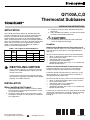
1
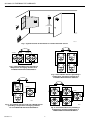
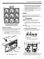
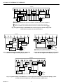
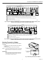
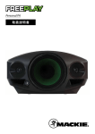
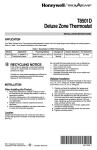
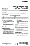
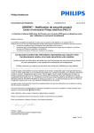
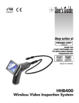
Q7100A,C,D
Thermostat Subbases
INSTALLATION INSTRUCTIONS
APPLICATION
The Q7100 Thermostat Subbases provide electronic
control of commercial 24 Vac single or multistage heat
pump or conventional heating and cooling systems.
Select models have terminals for light emitting diodes
LEDs, remote temperature sensors and remote setback
timer. The LED models have up to two field configurable
LEDs and up to two factory assigned LEDs. Refer to
Table 1. All Q7100 Thermostat Subbases require a
common wire to the supply power.
3. Installer must be a trained, experienced service
technician.
4. After completing installation, use these instructions
to check out the product operation.
CAUTION
Disconnect power supply to prevent electrical
shock or equipment damage.
Location
Subbase without Remote-Mounted Temperature Sensor
Table 1. Description of Q7100 Subbases.
Use
Q7100 T7100
a
Install the subbase about 5 ft (1.5m) above the floor in an
area with good air circulation at average temperature.
See Fig. 1.
Stagesa
System
A
D or F Conventional
C
E or F Heat pump
D
E or F Heat pump
Heat
Cool
Figs.
1 or 2
1 or 2
8-9
1, 2 or 3 1 or 2
1 or 2
10-14
1 or 2
15
Depends on the model.
RECYCLING NOTICE
If this control is replacing a control that contains
mercury in a sealed tube, do not place your old
control in the trash.
Contact your local waste management authority
for instructions regarding recycling and the proper
disposal of the old thermostat.
INSTALLATION
When Installing this Product...
1. Read these instructions carefully. Failure to follow
the instructions can damage the product or cause
a hazardous condition.
2. Check the ratings given in the instructions and on
the product to make sure the product is suitable for
your application.
®U.S. Registered Trademark
Copyright © 1996 Honeywell Inc. •
• All Rights Reserved
Do not install the subbase where it can be affected by:
— drafts, or dead spots behind doors and in corners.
— hot or cold air from ducts.
— radiant heat from sun or appliances.
— concealed pipes and chimneys.
— unheated (uncooled) areas such as an outside wall
behind the thermostat.
Subbase with Remote-Mounted Temperature Sensor(s)
Install the subbase in an area that is accessible for
setting and adjusting the temperature and settings.
Install the remote-mounted sensor(s) about 5 ft (1.5m)
above the floor in an area with good air circulation at
average temperature. See Fig. 1.
Do not mount the sensor(s) where it can be affected by:
— drafts, or dead spots behind doors and in corners.
— hot or cold air from ducts.
— radiant heat from sun or appliances.
— concealed pipes and chimneys.
— unheated (uncooled) areas such as an outside wall
behind the thermostat.
If more than one remote sensor is required, they must be
arranged in a temperature averaging network consisting
of two, three, four, five or nine sensors. See Fig. 2
through 6.
X-XX UL
69-0931-3
Q7100A,C,D THERMOSTAT SUBBASES
YES
NO
NO
5 FEET
[1.5 METERS]
NO
M10074
Fig. 1. Typical location of thermostat or remote-mounted sensor.
SUBBASE
SUBBASE
T
T
T
T
T7047C
T7047G
T7047C
T7047G
T
T
T
T
T
T
T7047C
M4838
T
T
T7047C
T
T
T
T
Fig. 2. Two T7047G Sensors providing a
temperature averaging network for a
T7100/Q7100 Thermostat/Subbase.
M4840
Fig. 4. Four T7047C Sensors providing a
temperature averaging network for a
T7100/Q7100 Thermostat Subbase.
SUBBASE
T
T
SUBBASE
T7047C
T
T
T
T
T7047G
T7047G
T7047G
T
T
T7047C
T
T
T
T7047G
T
T7047G
M4839
T
Fig. 3. Two T7047C Sensors and one T7047G Sensor
providing a temperature averaging network
for a T7100/Q7100 Thermostat/Subbase.
69-0931—3
T
T
T
T7047G
T
T
T
T
M4841
Fig. 5. Five T7047G Sensors providing a
temperature averaging network for a
T7100/Q7100 Thermostat/Subbase.
2
Q7100A,C,D THERMOSTAT SUBBASES
3. Remove the subbase from the wall and drill two
3/16 inch holes in the wall (if drywall) as marked. For
firmer material such as plaster or wood, drill two
7/32 inch holes. Gently tap anchors (provided) into
the drilled holes until flush with the wall.
4. Position the subbase over the holes, pulling wires
through the wiring opening.
5. Loosely insert the mounting screws into the holes.
6. Tighten mounting screws.
SUBBASE
T
T7047C
T
T7047C
T
T7047C
T
T
T7047C
T
T7047C
T
T7047C
T
T
T
T
T
T7047C
T
T7047C
T
T
T
WIRING
T
All wiring must comply with local electrical codes and
ordinances. Refer to Fig. 9 through 15 for typical
hookups. A letter code is located near each terminal for
identification.
T7047C
T
T
CAUTION
T
Disconnect power before wiring to prevent
electrical shock or equipment damage.
1. Loosen the terminal screws on the back of the
thermostat and connect the system wires. See
Fig. 8.
M4842
Fig. 6. Nine T7047C Sensors providing a
temperature averaging network for a
T7100/Q7100 Thermostat/Subbase.
IMPORTANT
Use 18 gauge, color-coded thermostat cable for
proper wiring.
Subbase Installation
2. Securely tighten each terminal screw.
3. Push excess wire back into the hole.
4. Plug the hole with nonflammable insulation to
prevent drafts from affecting the thermostat.
The subbase can be mounted horizontally on the wall or
a 2 in. x 4 in. wiring box. Position the subbase horizontally on the wall or on a 2 in. x 4 in. wiring box.
1. Position and level the subbase (for appearance
only). The thermostat will function properly even
when not level.
2. Use a pencil to mark the mounting holes. See Fig. 7.
FOR STRAIGHT
INSERTION STRIP
5/16 IN. (8 MM).
WALL
FOR WRAPAROUND
INSERTION STRIP
7/16 IN. (11 MM).
WIRES
THROUGH WALL
M4826
Fig. 8. Proper wiring technique.
SUBBASE
B
O
G
Y
X
W
RH
RC
WALL
ANCHORS
(2)
COMPRESSOR
CONTACTOR
HEAT
RELAY OR
VALVE COIL
FAN
RELAY
COOL
DAMPER
MOUNTING
HOLES
MOUNTING
SCREWS
HEAT
DAMPER
M6531
1
L1
(HOT)
L2
1 POWER SUPPLY. PROVIDE DISCONNECT MEANS
AND OVERLOAD PROTECTION AS REQUIRED.
M4831A
LEDS
Fig. 9. Typical hookup of Q7100A1044 in a one-stage
heat and one-stage cool conventional system.
Fig. 7. Mounting the subbase.
3
69-0931—3
Q7100A,C,D THERMOSTAT SUBBASES
SUBBASE
RC
O
Y1
Y2
G
X
W1
W2
B
RH
T
T
D
D
3
COOL
DAMPER
COMPRESSOR
CONTACTOR 2
FAN
RELAY
COMPRESSOR
CONTACTOR 1
REMOTE
TEMPERATURE
SENSOR
HEAT
RELAY 2
HEAT
RELAY 1
1
HEAT
DAMPER
REMOTE
SETBACK
TIMER
2
2
L1
(HOT)
L1
(HOT)
L2
L2
1 CAUTION:
EQUIPMENT DAMAGE WILL OCCUR IF POWER IS CONNECTED TO THE D TERMINALS.
2 POWER SUPPLY. PROVIDE DISCONNECT MEANS AND OVERLOAD PROTECTION AS REQUIRED.
3 JUMPER RC TERMINAL TO RH TERMINAL WHEN INSTALLED ON A SYSTEM WITH ONE TRANSFORMER.
M4837A
Fig. 10. Typical hookup of Q7100A1010 in a two-stage heat and two-stage cool
conventional system with two transformers.
SUBBASE
B
O
W
G
SUBBASE
X
Y
X1
R
COMPRESSOR
CONTACTOR
FAN
RELAY
HEAT
RELAY
E
W1
G
HEAT
RELAY
X
X1
R
COMPRESSOR
CONTACTOR
FAN
RELAY
EQUIPMENT
EM. HT.
RELAY
EQUIPMENT
Y1
MONITOR
MONITOR
COOL
CHANGEOVER
VALVE
L1
(HOT)
L1
(HOT)
HEAT
CHANGEOVER
VALVE
L2
1
L2
1
M11088
Fig. 11. Typical hookup of Q7100C1024 in a one-stage
heat and one-stage cool heat pump system.
POWER SUPPLY. PROVIDE DISCONNECT MEANS AND
OVERLOAD PROTECTION AS REQUIRED.
M4843A
Fig. 12. Typical hookup of Q7100D in a one-stage
heat and one-stage cool heat pump system.
SUBBASE
X
W2
O
AUX.
HEAT
RELAY
W1
B
E Y1 R
X1
EQUIPMENT
FAN
RELAY
T
T
D
D
SENSOR
MONITOR
HEAT
RELAY
HEAT
CHANGEOVER
VALVE
COOL
CHANGEOVER
VALVE
G
TIMER
EM. HT.
RELAY
COMPRESSOR
CONTACTOR
L1
(HOT)
L2
M11089
Fig. 13. Typical hookup of Q7100C1016 in a two-stage heat and one-stage cool heat pump system.
Includes remote temperature sensor and remote setback timer.
69-0931—3
4
Q7100A,C,D THERMOSTAT SUBBASES
SUBBASE
O
X
E
B
G
W2
Y2
W1
Y1
X2
X4
X1
X3
T
R
T
D
D
5
COOL
CHANGEOVER
VALVE
FAN
RELAY
COMPRESSOR
CONTACTOR 2
HEAT
RELAY 2
REMOTE
TEMPERATURE
SENSOR
EQUIPMENT
4
MONITOR 2
3
1
HEAT
CHANGEOVER
VALVE
EM. HT.
RELAY
COMPRESSOR
CONTACTOR 1
HEAT
RELAY 1
2
EQUIPMENT
L1
(HOT)
MONITOR 1
REMOTE
SETBACK
TIMER
L2
1
CAUTION: EQUIPMENT DAMAGE WILL OCCUR IF POWER IS CONNECTED TO THE D TERMINALS.
2
POWER SUPPLY. PROVIDE DISCONNECT MEANS AND OVERLOAD PROTECTION AS REQUIRED.
3
EM. HEAT RELAY DOES NOT CYCLE. TO TURN OFF THE EM. HEAT, GO TO SYSTEM SELECTION AND CHOOSE HEAT.
4
SELECT MODELS HAVE LEDS.
5
X2 AND X4 NEED TO BE JUMPERED TO TERMINAL X.
M4835A
Fig. 14. Typical hookup of Q7100C1008 in a two-stage heat and two-stage cool heat pump system.
Includes remote temperature sensor and remote setback timer.
SUBBASE
B
O
X
E
W3
G
Y2
Y1
X4
X1
X3
R
T
T
D
D
4
COOL
CHANGEOVER
VALVE
HEAT
CHANGEOVER
VALVE
FAN
RELAY
EM. HT.
RELAY
COMPRESSOR
CONTACTOR 2
EQUIPMENT
MONITOR 2
AUX. HT.
RELAY
COMPRESSOR
CONTACTOR 1
REMOTE
TEMPERATURE
SENSOR
1
EQUIPMENT
3
MONITOR 1
L1
(HOT)
L2
2
REMOTE
SETBACK
TIMER
1
CAUTION: EQUIPMENT DAMAGE WILL OCCUR IF POWER IS CONNECTED TO THE D TERMINALS.
2
POWER SUPPLY. PROVIDE DISCONNECT MEANS AND OVERLOAD PROTECTION AS REQUIRED.
3
SELECT MODELS HAVE LEDS.
4
X4 NEEDS TO BE JUMPERED TO TERMINAL X.
M4834B
Fig. 15. Typical hookup of Q7100C1073 in a three-stage heat and one-stage cool heat pump system.
Includes remote temperature sensor and remote setback timer.
Mounting Thermostat on Subbase
Mount the thermostat on the subbase after the subbase
is installed.
1. Engage tabs at the top of thermostat and subbase.
See Fig. 16.
2. Press lower edge of case to close and latch.
A. ENGAGE TABS AT TOP OF
THERMOSTAT AND SUBBASE.
NOTE: To remove the thermostat from the wall, first pull
out at the bottom of the thermostat; remove top
last.
B. PRESS LOWER
EDGE OF CASE
TO LATCH.
IMPORTANT
Refer to the thermostat installation instructions
for Installer Setup, Settings, Installer Self-Test
and Troubleshooting information.
M6799A
Fig. 16. Mounting thermostat on subbase.
5
69-0931—3
Q7100A,C,D THERMOSTAT SUBBASES
Home and Building Control
Honeywell Inc.
Honeywell Plaza
P.O. Box 524
Minneapolis, MN 55408-0524
69-0931—3
Rev. 2-98
L. C.
Home and Building Control
Honeywell Limited-Honeywell Limitée
155 Gordon Baker Road
North York, Ontario
M2H 2C9
6
www.honeywell.com