1
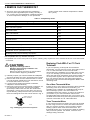
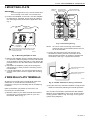
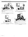
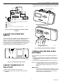
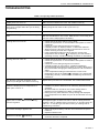
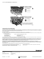
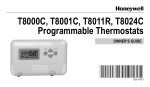
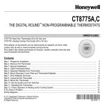
CT3451
Programmable Thermostat
OWNER’S GUIDE
MERCURY NOTICE
If this control is replacing a control that contains
mercury in a sealed tube, do not place your old
control in the trash. Dispose of it properly.
Contact your local waste management authority
for instructions regarding recycling and the
proper disposal of an old control.
1 PREPARE FOR INSTALLATION
Programmable Heat and/or Cool
Low Voltage (20 to 30 Vac) Thermostat and Wallplate
❑ Check Table 1 to make sure this thermostat is
compatible with your system. If not, return it to the
retailer.
❑ Acquire tools and items, as needed. See Fig. 1.
Congratulations on the purchase of your new thermostat!
More than 100 years of Honeywell engineering produced
this thermostat that can provide you with a more
comfortable and convenient living environment.
Your new thermostat automatically controls the
temperature in your home, keeping you comfortable
while saving energy when programmed according to
these instructions.
SCREWDRIVER
HAND OR POWER
DRILL WITH 3/16 INCH
DRILL BIT, IF NEEDED TO
DRILL HOLES IN WALL
Direct questions about this thermostat to our Web site at
www.honeywell.com/yourhome or call the customer
information line at 1-800-468-1502.
WIRE CUTTER/STRIPPER IF NEEDED TO STRIP WIRES
MERCURY
SWITCH
LEVEL, IF NEEDED TO LEVEL
THERMOSTAT FOR APPEARANCE
M20551
Fig. 1. Required installation tools/supplies.
TYPICAL LOCATION OF A MERCURY
SWITCH IN A THERMOSTAT
M10614
® U.S. Registered Trademark
Copyright © 2003 Honeywell •
•All Rights Reserved
69-1620-1
CT3451 PROGRAMMABLE THERMOSTAT
2 REMOVE OLD THERMOSTAT
❑ Test to be sure your heating and air conditioning
systems (where applicable) are working correctly. If
not, contact your local heating/air conditioning dealer.
To avoid compressor damage, do not operate the
cooling system when outdoor temperature is below
50°F (10°C).
Table 1. Compatibility Chart.
System Type
Compatible With CT3451
Gas—standing pilot
Yes
Gas—electronic ignition
Yes
Gas-fired boilers
Yesa
Gas—750 millivolt
Yes
Oil-fired boilers
Yesa
Oil-fired furnace
Yes
Electric furnace
Yes
Electric air conditioning
Yes
Single stage heat pumps (no backup or auxiliary heat)
Yes
Baseboard electric (120/240 line volt)
No
Multistage heat pumps/multistage equipment
No
Not compatible with any 120/240 volt circuit.
with 2-wire Honeywell zone valves. Isolating relay required for zone valves that have a 3-wire thermostat
connection.
aCompatible
Replacing Clock WIth C or C1 Clock
Terminals
CAUTION
Equipment Damage Hazard.
Handling wires during installation can
damage equipment.
Disconnect power at furnace or main breaker/
fuse box before beginning installation.
If you are replacing a Honeywell Chronotherm®
Thermostat, you may find one or two wires that go to the
C or C1 clock terminals on the Chronotherm®
Thermostat wiring wallplate. Do not allow them to touch,
or you can damage your transformer. Disconnect the
wires and wrap them separately using electrical tape; do
not wrap them together. Do not place the wires where
they can interfere with the new thermostat operation.
Record the colors and terminal designation labels of the
remaining wires.
❑ Carefully unpack your new thermostat and wallplate
and save package of screws, instructions and receipt.
❑ Remove the cover from the old thermostat. If it does
not snap off when pulled firmly from the bottom, check
for screw that locks on the cover.
❑ Loosen screws holding thermostat to subbase,
wallplate or wall and lift away.
❑ Disconnect wires from old thermostat or subbase. As
you disconnect each wire, use the wiring labels
(enclosed) to label each wire with the old terminal
designation. If there are only two wires, they do not
require labeling. Wrap wires around a pencil to keep
them from falling back into the wall as shown in Fig. 2.
Six or More Thermostat Wires
If there are six or more wires connected to the thermostat
(excluding clock wires attached to terminals), you
probably have a variation of a multistage heat pump or
other multistage system. The thermostat is not
compatible with these systems, so return the product to
your retailer. If you want information about which
programmable thermostats work with your system, visit
our Web site at www.honeywell.com/yourhome or call the
customer information line at 1-800-468-1502.
WIRES THROUGH
WALL OPENING
Three Thermostat Wires
If you have three wires for heating only and can operate
the fan using the Fan On switch, this thermostat works
with your system. However, some hot water (zoned)
heating systems have three thermostat wires. The
thermostat works only if a contractor installs an isolating
relay on these systems. For details, contact a local
heating/cooling contractor.
M5136
Fig. 2. Wrapping wires around pencil.
69-1620—1
2
CT3451 PROGRAMMABLE THERMOSTAT
3 MOUNT WALLPLATE
TERMINAL
SCREW
IMPORTANT
Level for appearance only. The thermostat functions normally even when not mounted level.
FOR STRAIGHT
INSERTION STRIP
5/16 IN. (8 MM)
FOR WRAPAROUND
STRIP 7/16 IN. (11 MM)
G
❑ Position the wallplate on the wall. Level the wallplate
for appearance, if desired. Use a pencil to mark the
two mounting holes that best fit the application. See
Fig. 3.
Rc
R
WALL
1
WALL
ANCHORS (2)
W
B
Y
O
M12559A
Fig. 4. Connecting wiring.
MOUNTING
SCREWS (2)
1
WALLPLATE
NOTE: To ensure correct mounting of thermostat,
restrict all wiring to the shaded area in the center of the terminals.
WHEN USING WALL ANCHORS, DRILL 3/16 INCH
HOLES FOR DRYWALL, 7/32 INCH HOLES FOR
PLASTER OR WOOD.
M12202A
❑ Loosen the terminal screws and slip each wire
beneath its matching terminal. The shape of the
terminals permit insertion of straight or wraparound
connections. See Fig. 5. Tighten the terminals.
Fig. 3. Mounting wallplate to wall.
❑ Remove the wallplate from the wall and drill two 3/16in. holes in the wall (if drywall). For firmer wall material
such as plaster or wood, drill 7/32-in. holes. Gently tap
provided anchors into the drilled holes until flush with
the wall.
❑ Reposition the wallplate, pulling wires through the
wiring opening. Loosely insert the mounting screws
into the holes.
❑ Level for appearance only; the thermostat functions
correctly even when not level. Tighten the mounting
screws.
FOR WRAPAROUND, STRIP
7/16 IN. (11 mm)
FOR STRAIGHT INSERTION,
STRIP 5/16 IN. (8 mm)
4 WIRE WALLPLATE TERMINALS
M12537
All wiring must comply with local electrical codes and
ordinances. If unsure about household wiring
procedures, call your local heating and air conditioning
contractor.
Fig. 5. CT3451 methods for wiring connection.
❑ Plug the hole in the wall with insulation to help prevent
drafts from adversely affecting thermostat operation.
Refer to the labels you placed on wires when you
removed your old thermostat.
The CT3451 Thermostat is powered with 3AA alkaline
batteries and is adaptable to most 18 to 30 Vac heatingcooling systems. Refer to Fig. 6 through 10 for typical
system wiring diagrams.
❑ Match the letter of your old thermostat wire with the
terminal of the corresponding letter on your new
thermostat. Refer to Fig. 4.
3
69-1620—1
CT3451 PROGRAMMABLE THERMOSTAT
THERMOSTAT
THERMOSTAT
G
G
Rc
Rc
R
3
R
B
B
Y
Y
O
HEAT
RELAY
1
FAN
RELAY
L1
(HOT)
FAN
COIL
W
W
O
2
COOL
DAMPER
COMPRESSOR
CONTACTOR
2
COOLIING
CONTRACTOR
COIL
1
L1
(HOT)
HEAT
DAMPER
L2
24V
L2
TRANSFORMER
1
POWER SUPPLY. PROVIDE DISCONNECT MEANS AND OVERLOAD
PROTECTION AS REQUIRED.
2
CAN BE USED FOR CHANGEOVER VALVE ON SINGLE-STAGE HEAT
PUMP SYSTEMS.
3
JUMPER R TO Rc.
1
POWER SUPPLY. PROVIDE DISCONNECT MEANS
AND OVERLOAD PROTECTION AS REQUIRED.
M20537
Fig. 8. Typical cool system hookup with 3-wire,
cool-only system.
M20510
Fig. 6. Typical heat-cool system hookup with single
transformer.
THERMOSTAT
G
Rc
R
THERMOSTAT
G
W
Rc
Y
2
B
O
R
W
3
B
FAN
RELAY
Y
O
COOL
DAMPER
3
HEAT
DAMPER
1
L1
(HOT)
1
L1
(HOT)
L2
HEATING
RELAY AND
FAN COIL
1
COOLING
TRANSFORMER
24V
1
POWER SUPPLY. PROVIDE DISCONNECT MEANS
AND OVERLOAD PROTECTION AS REQUIRED.
M20536
69-1620—1
HEAT
RELAY
L2
HEATING
TRANSFORMER
1
POWER SUPPLY. PROVIDE DISCONNECT MEANS AND OVERLOAD
PROTECTION AS REQUIRED.
2
REMOVE RC TO R JUMPER WHEN INSTALLED ON A TWO TRANSFORMER
SYSTEM.
3
Fig. 7. Typical heat system hookup with 2-wire, heatonly system.
COMPRESSOR
CONTACTOR
CAN BE USED FOR CHANGEOVER VALVE ON SINGLE-STAGE HEAT
PUMP SYSTEMS.
M20511
Fig. 9. Typical heat-cool system hookup with two
transformers.
4
CT3451 PROGRAMMABLE THERMOSTAT
❑ Swing down the thermostat and press the lower edge
of the thermostat onto the wallplate to latch. See Fig.
12.
T8002 THERMOSTAT
G
Rc
R
DASHED LINES INDICATE TABS
ON BACK OF THERMOSTAT
3
W
4
FAN
RELAY
Y
2
B
O
COOL
CHANGEOVER
VALVE
COMPRESSOR
CONTACTOR
1
L1
(HOT)
Hold
Sele
ct
HEAT
CHANGEOVER
VALVE
FA
Auto N
On
L2
TRANSFORMER
1
POWER SUPPLY. PROVIDE DISCONNECT MEANS AND OVERLOAD
PROTECTION AS REQUIRED.
2
JUMPER Y TO W.
3
JUMPER R TO Rc.
4
Coo SYSTE
l Off
M
Hea
t
A ENGAGE TABS AT TOP OF THERMOSTAT
WITH SLOTS ON WALLPLATE.
M20512
USE EITHER O OR B FOR HEAT PUMP CHANGEOVER.
Fig. 10. Typical single-stage heat pump system
hookup.
PM
TUE
Hold
Selec
5 ADJUST FAN OPERATION
SWITCH
t
FA
Auto N
On
The thermostat fan operation switch, labeled fuel switch
in Fig. 11, is set at the factory in the F (gas/oil fuel)
position. This is the correct setting for most systems. If
you have an electric heat system, set the switch to the E
(electric) position. The E setting allows the fan to turn on
immediately with the heating equipment in a system
where the G terminal is connected.See Fig. 11.
Coo SYSTE
l Off M
Hea
t
B PRESS LOWER EDGE OF
CASE TO LATCH.
M20513
Fig. 12. Mounting thermostat to wallplate.
7 INSTALLING AND REPLACING
BATTERIES
E
The thermostat requires three AA alkaline batteries to
operate:
❑ Remove the battery door, located on the right side of
the thermostat, by pulling outward from the bottom.
See Fig. 13.
❑ Insert three AA alkaline batteries as shown in Fig. 13.
F
FAN OPERATION (FUEL) SWITCH
M20530
Fig. 11. Fan operation (fuel) switch.
NOTE: The thermostat shows a “bAtLo” message on
the digital display to alert the homeowner one to
two months before the batteries run out completely.
6 MOUNT THERMOSTAT TO
WALLPLATE
IMPORTANT
Homeowner should replace the batteries once a
year to prevent leakage and/or the heating/cooling system from shutting down due to lack of
battery power in the thermostat.
❑ Slide System switch to the Off position.
❑ Engage the tabs at the top of the thermostat and
wallplate.
5
69-1620—1
CT3451 PROGRAMMABLE THERMOSTAT
—
AA BATTERIES (3)
Release the keys to display the three-digit software revision code. (Information displayed varies
by model).
PM
Hold
TUE
Selec
t
M12583
—
FA
Auto N
On
Coo SYSTE
l Off M
Hea
t
Press the ▲ key. FC (factory configuration) displays. (A typical example is shown, but information displayed varies by model. This information
is for factory use only.)
M20514
M12584A
Fig. 13. Installing batteries.
❑ Setting °C or °F.
— Press the ▲ key again to display the current
setting.
— Press the ▼ key to change the °C or °F indication.
❑ Setting Heat Cycle Rate (see Table 2 for the cycle rate
options and equipment).
— Press the ▲ key to display the current heat cycle
rate setting of 1, 3, 4, 5, 9, or 12 cph.
❑ Restore power to the heating/cooling system.
8 CUSTOMIZE YOUR THERMOSTAT
Your Honeywell thermostat comes preset to the most
commonly used settings:
— Temperature (°F).
— Gas or oil forced air furnace.
— Aggressive algorithm control.
You can change these settings using the instructions that
follow. To exit at any time, press the ▲ key until End
displays.
M12589A
—
If the desired cycle rate is displayed, press the ▲
key to display heating and cooling algorithm
default.
—
To change the heat cycle rate, press the ▼ key
until your choice of 1, 3, 4, 5, 6, 9, or 12 is displayed.
Press the ▲ key to display the heating and
cooling temperature control algorithm configuration default.
Setting °F/°C Indication, Heat Cycle Rate,
Heating/Cooling Temperature Control
The following instructions provide information to change
the heating cycle rate to match the heating equipment
and to choose either the Fahrenheit (°F) or Celsius (°C)
display.
M12588A
NOTE: All four steps must be completed to save
changes to the °F/°C indication and the heat
cycle rate.
—
❑ Enter Installer Setup.
— Use ▼ or ▲ keys to set the temperature setpoint
to 52°F (11°C).
SET
HT.
M14691
—
M12582A
—
Press ▼ and ▲ keys simultaneously for more
than two seconds to enter Installer Setup.
69-1620—1
6
Press the ▼ key to change the heating and cooling control algorithm to C1 or C3.
C1 = Standard control algorithm.
C3 = Aggressive control algorithm (Default. Can
cause overshooting.)
CT3451 PROGRAMMABLE THERMOSTAT
—
Press the ▲ key. Current configuration (CC) is
displayed. A typical example is shown, but CC
varies by model. (This information is for factory
use only.)
NOTE: The heating and cooling program times are the
same. Changing your cooling Wake time also
changes your heating Wake time.
Leave is the time period you can set for an energy saving
temperature while you are away from home during the
day.
Return is the time period when you want the house at a
comfortable temperature when you come home during
the day.
M14692
❑ Exit Installer Setup.
— Press the ▲ key to save all changes and return to
normal operation.
Sleep is the time period when you can set an energysaving temperature while you are sleeping.
IMPORTANT
Always press the keys with your fingertip or similar blunt tool. Sharp instruments like pens and
pencil points can damage the keyboard.
PM
Setting Current Time and Day
1.
M12590A
NOTE: While setting the current time, the word SET is
displayed.
Table 2. Heating Cycle Rate.
System
To set current time, press Select twice. Press ▼
or ▲ key to set current time.
Cycle Per Hr
SET
Steam, gravity
1
Hydronic heat, condensing gas
furnacesa
3
Gas or oil forced air (default)
6
Electric heat
9
Special applications
4, 5, 12
PM
M12591A
aHigh
2.
To set day of week, press Select again. Press▼
or ▲ key to set current day.
SET
efficiency furnace (90+).
to the equipment manufacturer’s instructions.
bRefer
M18534
9 PROGRAM YOUR THERMOSTAT
To use the preprogrammed time and temperature
settings (see Table 3), press Hold to exit the
programming mode.
The thermostat is preprogrammed for your convenience
with the following time and temperature settings; see
Table 3. See energy saving charts at the end of this
document for energy-saving information.
Setting Weekday Program
Slide the System switch to the position, Heat or Cool,
that you want to program. A flame
(heating) or a
snowflake
(cooling) appears in the right side of the
display, when setting the program temperature.
Table 3. Preprogrammed Time
and Temperature Settings.
Period
Wake
Time
6:00 AM
Heat
Setpoint
70°F (21°C)
1.
Cool
Setpoint
78°F (26°C)
Leave
8:00 AM
62°F (17°C)
85°F (29°C)
Return
6:00 PM
70°F (21°C)
78°F (26°C)
Sleep
10:00 PM
62°F (17°C)
82°F (28°C)
Wake
a. Press Select. Press ▼ or ▲ key to set Wake
time.
SET
M18570
b. Press Select. Press ▼ or ▲ key to set Wake
temperature.
Wake is the time period when you want the house at a
comfortable temperature when you get up in the morning.
7
69-1620—1
CT3451 PROGRAMMABLE THERMOSTAT
Setting Saturday and Sunday Programs
To set the Saturday program:
SET
1.
M12625C
2.
Leave.
a. Press Select. Press ▼ or ▲ key to set Leave
time.
Wake
a. Press Select. Press ▼ or ▲ key to set Wake
time.
SET
SET
M20558
b. Press Select. Press ▼ or ▲ key to set Wake
temperature.
M18566
b. Press Select. Press ▼ or ▲ key to set Leave
temperature.
SET
SET
M20559
2.
M12627B
3.
Return
a. Press Select. Press ▼ or ▲ key to set Return
time.
Leave
a. Press Select. Press ▼ or ▲ key to set Leave
time.
SET
SET
M20560
b. Press Select. Press ▼ or ▲ key to set Leave
temperature.
M18567
b. Press Select. Press ▼ or ▲ key to set Return
temperature.
SET
SET
M20561
3.
M12629B
4.
Sleep
a. Press Select. Press ▼ or ▲ key to set Sleep
time.
Return
a. Press Select. Press ▼ or ▲ key to set Return
time.
SET
SET
M20562
b. Press Select. Press ▼ or ▲ key to set Return
temperature.
M18568
b. Press Select. Press ▼ or ▲ key to set Sleep
temperature.
SET
SET
M20563
M12631C
69-1620—1
8
CT3451 PROGRAMMABLE THERMOSTAT
4.
Setting Indefinite Temperature Hold
Sleep
a. Press Select. Press ▼ or ▲ key to set Sleep
time.
The Hold key allows you to indefinitely hold a
temperature. When Hold is active, the letters Hld are
displayed continuously. Hold can be canceled by
pressing the Hold key again.
SET
❑ Press Hold.
❑ Press ▼ or ▲ key to set indefinite temperature
setting.
M20564
b. Press Select. Press ▼ or ▲ key to set Sleep
temperature.
SET
M12641A
11 SET FAN AND SYSTEM
SWITCHES
M20565
5.
6.
Repeat steps 1-4 in Setting Saturday and Sunday
Program section to set the Sunday program.
Press Select. End is displayed. Programming is
complete. The thermostat reverts to displaying the
current day time and temperature in five seconds.
Manually control Fan and System settings using the
switches located at the bottom of the thermostat case.
See. Fig. 14 for switch locations.
SET
M18556
7.
Repeat programming steps to set heat or cool
program, as desired.
PM
TUE
Hold
Selec
t
10 OPERATE YOUR THERMOSTAT
FA
Auto N
On
Displaying Temperature Setting
Coo SYSTE
l Off M
Hea
❑ Press ▼ or ▲ key once to display present
temperature setting. After approximately five seconds,
the thermostat displays the current time and room
temperature.
t
M20515
Fig. 14. Time/temperature display and System/Fan
switches.
SET TEMPORARY
Fan Switch
❑ The Fan switch settings are:
On: The fan runs continuously. Use for
improved air circulation.
M20538
Setting Temporary Temperature Hold
Auto: Normal setting for most homes. In cooling,
the fan starts and stops with the cooling equipment. In heating, the fan is controlled directly by
the heating equipment and starts a few minutes
after the heating equipment turns on (on most
systems). When the thermostat fuel switch is
set to the E position for electric heat, the fan
starts and stops with the heating equipment.
❑ Press ▼ or ▲ key to set a temporary temperature
setting.
TEMPORARY
PM
WED
M12640A
❑ Slide the Fan switch on the thermostat to the desired
fan setting.
NOTE: The temporary temperature setting remains in
effect until the next program period. To cancel,
press Hold twice.
9
69-1620—1
CT3451 PROGRAMMABLE THERMOSTAT
System Switch
❑ The System switch settings control thermostat
operation as follows:
Cool: The thermostat controls the cooling
system.
Off: Both heating and cooling are off.
Heat: The thermostat controls the heating
system.
❑ Slide the System switch on the thermostat to the
desired system setting.
with the Fuel switch set to the E position for electric
heat, the fan starts immediately.
❑ Press the ▼ key to lower the temperature setting
below the room temperature. The heating equipment
should shut down.
Cooling System
CAUTION
Compressor Damage Hazard.
Operating at too low of an outdoor
temperature can cause compressor damage.
Do not operate cooling if outdoor temperature is
below 50°F (10°C).
Allow compressor to remain off for five minutes
before restarting.
Refer to manufacturer’s recommendations.
Heat and Cool Indicators
indicates a call for heat.
indicates a call for cool.
NOTE: In the programming mode, the
the
indicate System setting.
and
Minimum Off-Timer
1.
The thermostat minimum off-timer assures that the
compressor does not come on again for at least five
minutes after it turns off.
The minimum off-timer is triggered when the compressor
turns off and when the System switch position is
changed. If the compressor turns off when the setpoint is
changed, the minimum off-timer is triggered.
A flashing snowflake
is in effect.
indicates the minimum off-timer
12 CHECK OPERATION AFTER
INSTALLATION/PROGRAMMING
Heating System
❑ Slide the System switch to Heat and the Fan switch to
Auto.
❑ Press and hold the ▲ key to raise the temperature
several degrees above the room temperature to start
the heating equipment. When using the thermostat
69-1620—1
2.
Slide the System switch to Cool and the Fan switch
to Auto.
Press the ▼ key to lower the temperature setting
several degrees below the room temperature; the
cooling equipment should start. The fan starts and
stops with the cooling equipment.
NOTE: If the cooling system does not start immediately,
remember that the thermostat has a built-in minimum off-time of five minutes to protect the compressor.
3.
Press the ▲ key to raise the temperature setting
above the room temperature. Cooling system
should shut down.
Fan
❑ Slide the System switch to Off and the Fan switch to
On. The fan should run continuously.
❑ Slide the Fan switch to Auto. The fan should turn off.
Backlighting
❑ Press any key to light the display for approximately
ten seconds.
10
CT3451 PROGRAMMABLE THERMOSTAT
TROUBLESHOOTING
Table 4. Frequently Asked Questions.
If ...
Then ...
Display does not come on.
Make sure the batteries are fresh and installed correctly.
Temperature display does not go lower than
40°F (4°C) or higher than 99°F (37°C during
programming.
Your thermostat has reached the temperature limit. Be sure the
setting range is from 40°F to 99°F (4°C to 37°C).
Display shows flashing or steady “bAtLo.”
The batteries are low; replace them as soon as possible.
Temperature change occurs at the wrong
time.
Check the program times for the period in question. Be sure that
AM and PM indications are correct. Make sure the current day and
time are correct. Reprogram if necessary.
Heating does not come on.
• Check that the System switch is set to Heat.
• Check the system fuse or circuit breaker and replace or reset, if
necessary.
• Check for correct wiring and good connections.
• If display is blank or displays “bAtLo,” install fresh batteries.
• Allow time for the furnace to heat up and the fan to come on
before checking for heat at the register.
• If the temperature setting is higher than the current room
temperature and the flame
is displaying, the thermostat is
operating correctly. Contact a heating contractor for assistance.
Cooling does not come on.
• Check that the System switch is set to Cool.
• Check the system fuse or circuit breaker and replace or reset, if
necessary.
• Check for correct wiring and good connections.
• If display is blank or says “bAtLo,” install fresh batteries.
• The thermostat has a built-in time delay on cooling. Allow five to
ten minutes after changing the setting before the air conditioner
starts.
• If the temperature setting is lower than the current room
temperature and the snowflake
is displaying, the thermostat
is operating correctly. Contact an air conditioning contractor for
assistance.
The furnace cycles too frequently or the
system cycle length is too short or too long.
Adjust heat cycle rate in the Customize Your Thermostat section.
The thermostat current setting does not
match the displayed room temperature to
within plus or minus 1°.
• Plug the wiring hole in the wall behind the mounting plate with
insulation to prevent drafts that can adversely affect thermostat
operation.
• Be aware that it is normal for the current setting and the
displayed room temperature to differ occasionally.
• During recovery from setback or setup, setting and displayed
room temperatures can differ for up to 30 minutes after recovery
period.
System on indicator ( = heat;
= cool) is
lighted, but no warm or cool air is coming
from the registers.
Wait five minutes after seeing the flame or snowflake and check
the registers again. If there is no hot or cool air coming from the
registers, refer to “Heating does not come on” or “Cooling does not
come on.” If everything is checked contact you heating and air
conditioning contractor.
Thermostat backlight appears dim.
• Wait until Replace Battery indicator is illuminated and replace
batteries.
• Replace batteries now.
System on indicator
• MInimum off-timer is in effect. Wait five minutes until the
minimum off-timer is complete.
is flashing.
11
69-1620—1
CT3451 PROGRAMMABLE THERMOSTAT
PERCENT OF HEATING
COSTS YOU CAN SAVE
SAVINGS FOR ONCE-A-DAY
10°F (5°C) DECREASE*
6 TO
9
12
14
16
TO
TO
TO
TO
8%
HEAT
11%
13%
15%
18%
PERCENT OF COOLING
COSTS YOU CAN SAVE
SAVINGS FOR ONCE-A-DAY
10°F (5°C) INCREASE*
COOL
7 TO
9%
10 TO 11%
12 TO 14%
14 TO 19%
* YOUR SAVINGS DEPENDS ON HOME SIZE AND
ACTUAL HEAT LOSS OR GAIN, GEOGRAPHIC
LOCATION, FREQUENCY OF TEMPERATURES
CHANGE, AND RANGE IN DEGREES OF CHANGE.
M12545
Limited One-Year Warranty
Honeywell warrants this product, excluding battery, to be free from defects in the workmanship or materials, under normal use and service, for a period of
one (1) year from the date of purchase by the consumer. If, at any time during the warranty period, the product is defective or malfunctions, Honeywell shall
repair or replace it (at Honeywell’s option) within a reasonable period of time.
If the product is defective,
(i) return it, with a bill of sale or other dated proof of purchase, to the retailer from which you purchased it, or
(ii) package it carefully, along with proof of purchase (including date of purchase) and a short description of the malfunction, and mail it, postage prepaid,
to the following address:
Honeywell Return Goods
Dock 4, MN10-3860
1885 Douglas Dr N
Golden Valley, MN 55422
Canada: Honeywell Limited/Honeywell Limitée
Product Services ON15
35 Dynamic Dr
Scarborough, Ontario M1V 4Z9
This warranty does not cover removal or reinstallation costs. This warranty shall not apply if it is shown by Honeywell that the defect or malfunction was
caused by damage which occurred while the product was in the possession of a consumer.
Honeywell’s sole responsibility shall be to repair or replace the product within the terms stated above. HONEYWELL SHALL NOT BE LIABLE FOR ANY
LOSS OR DAMAGE OF ANY KIND, INCLUDING ANY INCIDENTAL OR CONSEQUENTIAL DAMAGES RESULTING, DIRECTLY OR INDIRECTLY,
FROM ANY BREACH OF ANY WARRANTY, EXPRESS OR IMPLIED, OR ANY OTHER FAILURE OF THIS PRODUCT. Some states do not allow the
exclusion or limitation of incidental or consequential damages, so this limitation may not apply to you.
THIS WARRANTY IS THE ONLY EXPRESS WARRANTY HONEYWELL MAKES ON THIS PRODUCT. THE DURATION OF ANY IMPLIED
WARRANTIES, INCLUDING THE WARRANTIES OF MERCHANTABILITY AND FITNESS FOR A PARTICULAR PURPOSE, IS HEREBY LIMITED TO
THE ONE YEAR DURATION OF THIS WARRANTY. Some states do not allow limitations on how long an implied warranty lasts, so the above limitation
may not apply to you.
This warranty gives you specific legal rights, and you may have other rights which vary from state to state.
If you have any questions concerning this warranty, please write
Honeywell Customer Relations, 1985 Douglas Dr N, MN10-1461, Golden
Valley, MN 55422. In Canada, write Retail Products ON15,
Honeywell Limited/Honeywell Limitée, 35 Dynamic Dr, Scarborough,
Ontario M1V 4Z9.
Automation and Control Solutions
Honeywell
1985 Douglas Drive North
Golden Valley, MN 55422
69-1620—1 J.S. 05-03
Honeywell Limited-Honeywell Limitée
35 Dynamic Drive
Scarborough, Ontario
M1V 4Z9
Printed in U.S.A. on recycled
paper containing at least 10%
post-consumer paper fibers.
www.honeywell.com/yourhome