1
MAXPRO-Net
Crosspoint Matrix Video Switching System
Operator’s Manual
HMXMU001056 - March 2005 - Rev. A
Rev. A
ISSUE
DATE
A
March 2005
REVISIONS
Initial Release (PCN1980)
ii
HMXMU001056
03/16/05
SOFTWARE LICENSE AGREEMENT
Honeywell International Inc.
165 Eileen Way, Syosset, NY 11791
.
You should carefully read the following terms and conditions. If you do not
consent to be bound by this License Agreement, you must promptly return
the unopened package to the person from whom you purchased it within
fifteen (15) days from date of purchase and your money will be refunded to
you by that person. If the person from whom you purchased this Software
fails to refund your money, contact HONEYWELL immediately at the
address shown above.
Important: This Software is security related. Access should be limited to
authorized individuals.
1. GRANT OF LICENSE. Subject to all terms and conditions hereof of
Honeywell International Inc. acting through its Security group ("HONEYWELL")
does hereby grant to the purchaser (the "Licensee") upon payment in full of the
published license fee, or other license fee agreed to in writing (the "License Fee")
a nontransferable, non exclusive license to use the enclosed software ("Licensed
Programs") provided herewith in Licensee's own business on a single computer
for a term commencing on the date of payment in full of the License Fee and
continuing in perpetuity unless terminated in accordance with the terms hereof.
2. PROPRIETARY RIGHTS. License hereby acknowledges that the Licensed
Programs including the algorithms contained therein are proprietary to
HONEYWELL. Licensee shall not sell, transfer, disclose, display or otherwise
make available any Licensed Programs or copies or portions thereof to any other
entity. Licensee agrees to secure and protect the Licensed Programs so as to
maintain the proprietary rights of HONEYWELL therein, including appropriate
instructions to and agreements with its employees.
3. DOCUMENTATION. The documentation supplied with the Licensed Programs
is the copyright property of HONEYWELL. Licensee shall not under any
circumstances divulge or permit to be divulged such documentation to any other
entity.
4. COPIES. Licensee shall not copy in whole or in part the Licensed Programs
or documentation provided however that Licensee shall be permitted to make
one (1) copy of the Licensed Programs solely for backup purposes provided that
all proprietary notices are reproduced thereon. Any such copy shall remain part
of the Licensed Programs and shall be subject to this agreement.
5. OBJECT CODE. Licensee understands and acknowledges that the Licensed
Programs consist of object code only and that HONEYWELL shall not supply
source code versions of the Licensed Programs. Licensee shall not create or
attempt to create by de-compilation or otherwise, the source code for the
Licensed Programs, or any part thereof.
6. SECURITY. Licensee acknowledges that the Licensed Programs are security
related and access to the Licensed Software should be limited to authorized
individuals. Licensee assumes full responsibility for use of the Licensed
Programs whether by authorized or unauthorized individuals. Licensee agrees
that the License Fee has been set in reliance upon the limitation on liability
contained herein and that such provisions are fair and not unconscionable.
HONEYWELL does not represent that the Licensed Programs may not be
compromised or circumvented, that the Licensed Programs will prevent any
personal injury or property loss by burglary, robbery, fire or otherwise, or that the
Licensed Programs will in all cases provide adequate warning or protection.
Licensee understands that a properly installed and maintained alarm may only
reduce the risk of burglary, robbery or fire without warning, but is not insurance or
a guarantee that such will not occur or that there will be no personal injury or
property loss as a result.
7.
DISCLAIMER OF WARRANTIES. HONEYWELL does not warrant that the
Licensed Programs will meet your requirements, that operation of the Licensed
Programs will be uninterrupted or error-free, or that all Licensed Programs’ errors
will be corrected. The entire risk as to the quality and performance of the
Licensed Programs is with you.
THE IMPLIED WARRANTIES OF
MERCHANTABILITY, FITNESS FOR A PARTICULAR PURPOSE AND
NONINFRINGEMENT ARE DISCLAIMED.
NO ORAL OR WRITTEN
INFORMATION OR ADVICE GIVEN BY HONEYWELL, ITS EMPLOYEES,
DISTRIBUTORS, DEALERS, OR AGENTS SHALL INCREASE THE SCOPE OF
THE ABOVE WARRANTIES OR CREATE ANY NEW WARRANTIES. SOME
JURISDICTIONS DO NOT ALLOW THE EXCLUSION OF IMPLIED
WARRANTIES, SO THE ABOVE EXCLUSION MAY NOT APPLY TO YOU. IN
THAT EVENT, ANY IMPLIED WARRANTIES ARE LIMITED IN DURATION TO
NINETY (90) DAYS FROM THE DATE OF DELIVERY OF THE LICENSED
PROGRAMS. This warranty gives you specific legal rights. You may have other
rights, which vary from state to state.
Rev. A
iii
8. LIMITATION OF REMEDIES. Licensee's exclusive remedy shall be either the
replacement of any diskette or other media not meeting the limited warranty set
forth above and which is returned to HONEYWELL with a copy of Licensee's paid
invoice or, if HONEYWELL is unable to deliver a replacement that is free of
defects, Licensee may terminate this Agreement by returning the Licensed
Programs and thereupon the License Fee shall be refunded. HONEYWELL shall
have no obligation under this Agreement if the Licensed Programs are altered or
improperly repaired or serviced by anyone other than HONEYWELL factory
service. For warranty service, return Licensed Programs transportation prepaid,
to HONEYWELL Factory Service, 165 Eileen Way, Syosset, New York 11791.
9. LIMITATION OF LIABILITY. REGARDLESS OF WHETHER ANY REMEDY
SET FORTH IN THIS AGREEMENT FAILS OF ITS ESSENTIAL PURPOSE, IN
NO EVENT WILL HONEYWELL OR ITS SUPPLIERS BE LIABLE TO YOU FOR
ANY SPECIAL, CONSEQUENTIAL, INDIRECT OR SIMILAR DAMAGES,
INCLUDING ANY LOST PROFITS OR LOST DATA ARISING OUT OF THE
USE OR INABILITY TO USE THE LICENSED PROGRAMS OR ANY DATA
SUPPLIED THEREWITH EVEN IF HONEYWELL OR ANYONE ELSE HAS
BEEN ADVISED OF THE POSSIBILITY OF SUCH DAMAGES, OR FOR ANY
CLAIM BY ANY OTHER PARTY. THIS PROVISION IS INCLUDED FOR THE
BENEFIT OF HONEYWELL AND ITS LOCAL REPRESENTATIVES, AND IS
ENFORCEABLE BY EACH OF THEM.
SOME JURISDICTIONS DO NOT ALLOW THE LIMITATION OR EXCLUSION
OF LIABILITY FOR INCIDENTAL OR CONSEQUENTIAL DAMAGES, SO THE
ABOVE LIMITATION OR EXCLUSION MAY NOT APPLY TO YOU.
IN NO CASE SHALL THE LIABILITY OF THE LICENSED PROGRAMS’
PROVIDERS OR OF HONEYWELL EXCEED THE PURCHASE PRICE PAID
FOR THE PRODUCT.
10. REGISTRATION. In order to qualify to receive notification of HONEYWELL
updates to the Licensed Programs, Licensee must complete and return a
Registration Form to HONEYWELL within twenty (20) days from date of
purchase. Notwithstanding, HONEYWELL is under no obligation to release
updates to the Licensed Programs.
11. TERMINATION. Upon the breach or non-compliance with any term or
provision of this agreement, HONEYWELL shall have the right to terminate the
license granted hereby by written notice to Licensee. Upon such termination
Licensee shall immediately turn over to HONEYWELL all copies of the Licensed
Programs and any documentation supplied in connection therewith. Such
remedy shall be in addition to and cumulative to any other remedies
HONEYWELL may have at law or in equity with respect to such breach or noncompliance.
12. GENERAL. This agreement is the complete and exclusive statement of the
understanding of the parties hereto with respect to the transaction contemplated
hereby and supersedes any and all prior proposals, understandings and
agreements. This Agreement may not be modified or altered except by a written
instrument signed by Licensee and an authorized representative of
HONEYWELL, its rights, duties or obligations under this Agreement to any
person or entity, in whole or in part. If any provision of this Agreement is invalid
under any applicable stature or rule of law it is to that shall be governed by the
laws of the State of New York and the sole venue for suit shall be in an
appropriate state or federal court located in the State and City of New York. The
failure of HONEYWELL to exercise in any respect any rights provided for herein
shall not be deemed a waiver of such right or any further Agreement may be
brought more than two (2) years after the date such cause of action shall have
arisen. HONEYWELL shall have the right to collect from Licensee any expensed
incurred including attorneys' fees in enforcing its right under this agreement.
HMXMU001056
03/16/05
PATENT AND TRADEMARK INFORMATION
Portions of MAX-1000, its software, and its components are protected by one or more of
the following patents or trademarks.
Australian Patent
US Patent
British Patents
Singaporean Patent
Australian Trademarks
US Trademark
Rev. A
674652, 693914
5923364, 5745166
GB2305061 B, GB2323739 B, GB2323740 B, GB2323741 B
9700491-5
679926, 679927, 679928, 679929, 679930, 679931
75/142790
iv
HMXMU001056
03/16/05
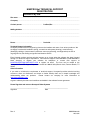
MAXPRO-Net TECHNICAL SUPPORT
REGISTRATION
License Key No:
Site name: ..........................................................................................................................................................
Company:..........................................................................................................................................................
Contact person: ..................................................
Position/title:...................................................................
Mailing Address: ...............................................................................................................................................
.............................................................................................................................................................................
.............................................................................................................................................................................
Phone:...................................................................
Facsimile:........................................................................
Technical Support Information
Honeywell provides technical support by phone to the installers and users of our various products. We
are happy to assist with installation (wiring, connections and system planning), commissioning
(identifying cabling or interconnection problems, macro programming, reconfigurations) as well as
ongoing service, fault finding and general maintenance advice.
Every licensed product receives technical support at no charge when the software has been licensed
through our technical support department. Call technical support at 972-620-6500 (1-800-796-2288 in
North America) to register your software via telephone or contact tech support at
[email protected] to register via email. The form can be mailed to the
Honeywell’s Technical Support Department located at 12880-A Valley Branch Lane, Farmers Branch, TX
75234.
Other information
If you wish to minimize the requirement of technical support, Honeywell provides technical training
courses to allow our distributors and clients to further develop their own in depth knowledge and
understanding about our products.
Please contact our company for more information at
www.honeywellvideo.com.
I agree to abide by the terms and conditions as detailed in the software license agreement.
Please Sign/date and return to Honeywell Video Systems
_____________________________________
Signature
_______________________________
Date
Rev. A
v
HMXMU001056
03/16/05
MAXPRO-Net TECHNICAL SUPPORT
"BEFORE YOU CONTACT TECHNICAL SUPPORT"
License Key No:
Before you call requesting technical support you should obtain the following information. This will save
you time and money and allow our support staff to attend to your difficulties promptly.
Have you registered the site?
As discussed on the registration form, you must have pre-registered your new MAXPRO-Net software
license PRIOR to requesting our technical support services. This should be done immediately to
activate you MAXPRO-Net software.
What is the License key number?
You will need to know the license number for the MAXPRO-Net system you are ringing about. The
license number is detailed at the top of this page as well as on the rear side of the SYSTEM floppy disk.
It can also be read from the title and registration page displayed within the system configuration editor
program, SETMAX.
You're now ready to contact technical support!
You are now ready to call technical support. Telephone: 972-620-6500; Toll Free North America: 1-800796-2288. Our staff may need to research your inquiry. This may require time outside of the original
phone call.
Rev. A
vi
HMXMU001056
03/16/05
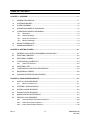
TABLE OF CONTENTS
CHAPTER 1: OVERVIEW .......................................................................................................................1-1
1.1
GENERAL DESCRIPTION.......................................................................................................... 1-1
1.2
SYSTEM KEYBOARDS .............................................................................................................. 1-2
1.3
OTHER EQUIPMENT ................................................................................................................. 1-2
1.4
ASSUMPTIONS MADE BY THIS MANUAL ................................................................................ 1-2
1.5
CONVENTIONS USED IN THIS MANUAL ................................................................................. 1-3
1.5.1 Keystrokes .................................................................................................................... 1-3
1.6.2 Numerical Range .......................................................................................................... 1-3
1.6.3 Points to Take Note of .................................................................................................. 1-3
1.6.4 Monitor messages ........................................................................................................ 1-4
1.6
MANUFACTURER'S NOTE ........................................................................................................ 1-4
1.7
ACKNOWLEDGEMENTS ........................................................................................................... 1-4
CHAPTER 2: GETTING STARTED.........................................................................................................2-1
2.1
ENTERING YOUR SELECTION NUMBERS HOW AND WHY? ................................................. 2-1
2.2
SELECTING A MONITOR .......................................................................................................... 2-2
2.3
SELECTING A CAMERA ............................................................................................................ 2-3
2.4
CONTROLLING A CAMERA PTZ ............................................................................................... 2-4
2.4.1 Other PTZ functions...................................................................................................... 2-5
2.5
SELECTING A VCR.................................................................................................................... 2-6
2.6
CONTROLLING A VCR FROM THE KEYBOARD....................................................................... 2-6
2.7
RECORDING A CAMERA........................................................................................................... 2-8
2.8
AUXILIARY DEVICES AND MULTIPLEXERS ............................................................................. 2-9
CHAPTER 3: USING SCAN SEQUENCES ............................................................................................3-1
3.1
WHAT IS A SCAN SEQUENCE?................................................................................................ 3-1
3.1.1 What is a Guard Tour?.................................................................................................. 3-1
3.2
STARTING A SCAN SEQUENCE............................................................................................... 3-2
3.3
HALTING A SCAN SEQUENCE................................................................................................. 3-3
3.4
PAUSING A SCAN SEQUENCE ................................................................................................ 3-4
3.5
MAKING A NEW SCAN SEQUENCE ......................................................................................... 3-5
3.6
EDITING A SCAN SEQUENCE .................................................................................................. 3-8
3.6.1 Overwrite With A New Camera Selection ..................................................................... 3-8
3.6.2 Delete This Camera Selection ...................................................................................... 3-9
3.6.3 Insert A New Camera Selection.................................................................................. 3-10
Rev. A
vii
HMXMU001056
03/16/05
TABLE OF CONTENTS, CONTINUED
3.7
CHANGING THE DWELL PERIOD........................................................................................... 3-11
3.8
INCREASING THE DWELL FOR ONE CAMERA ..................................................................... 3-13
CHAPTER 4: USING MACROS..............................................................................................................4-1
4.1
WHAT IS A MACRO? ................................................................................................................. 4-1
4.1.1
Salvo Camera Selections............................................................................................. 4-1
4.1.2 Camera Walks............................................................................................................... 4-1
4.1.3 Automated Control ....................................................................................................... 4-2
4.2
EXECUTING A MACRO ............................................................................................................. 4-2
4.3
MAKE A NEW MACRO............................................................................................................... 4-3
4.4
CAN I EDIT A MACRO?.............................................................................................................. 4-5
CHAPTER 5: MANAGING ALARMS ......................................................................................................5-1
5.1
WHAT ARE ALARMS?................................................................................................................ 5-1
5.2
EXTERNAL ALARM INPUTS ...................................................................................................... 5-2
5.3
CAMERA FAIL ALARMS............................................................................................................. 5-2
5.3.1 Lost Video ..................................................................................................................... 5-2
5.3.2 Low Level Video............................................................................................................ 5-2
5.4
PTZ SITE FAILED ALARMS........................................................................................................ 5-2
5.5
PTZ SITE TAMPER ALARMS ..................................................................................................... 5-3
5.6
VCR ALARMS............................................................................................................................. 5-3
5.7
OTHER DEVICE ALARMS.......................................................................................................... 5-3
5.8
THE ALARM STACK................................................................................................................... 5-3
5.9
STEPPING THROUGH THE ALARM STACK ............................................................................. 5-4
5.10
CLEARING AN ALARM ............................................................................................................. 5-4
CHAPTER 6: OTHER KEYBOARD FUNCTIONS...................................................................................6-1
6.1
FAST CAMERA SELECTION ..................................................................................................... 6-1
6.2
SETTING A NEW CAMERA VIEW (PTZ PRESET POSITION) ................................................... 6-1
6.3
RECALLING A CAMERA VIEW (PTZ PRESET POSITION) ........................................................ 6-3
6.4
CAMERA PTZ FLASHBACK .................................................................................................... 6-3
6.5
HIDING DISPLAYED TEXT......................................................................................................... 6-5
6.6
REVEALING SMARTEXT......................................................................................................... 6-5
Rev. A
viii
HMXMU001056
03/16/05
TABLE OF CONTENTS, CONTINUED
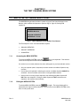
CHAPTER 7: THE TEXT CHANNEL MENU SYSTEM............................................................................7-1
7.1
WHAT IS THE TEXT CHANNEL MENU SYSTEM? .................................................................... 7-1
7.1.1 Accessing the MENU SYSTEM..................................................................................... 7-1
7.1.2 Exiting the MENU SYSTEM .......................................................................................... 7-1
7.2
MAKING SELECTIONS FROM THE MENU ............................................................................... 7-2
7.3
SIGN-ON KEYBOARD OPERATORS ......................................................................................... 7-3
7.4
SIGN-OFF KEYBOARD OPERATORS ....................................................................................... 7-4
7.5
CHANGE PIN NUMBER............................................................................................................. 7-5
CHAPTER 8: MESSAGE PROMPTS......................................................................................................8-1
8.1
INTRODUCTION ........................................................................................................................ 8-1
8.2
SELECTIONS............................................................................................................................. 8-1
8.3
SCAN ......................................................................................................................................... 8-3
8.4
PAN-TILT CONTROL.................................................................................................................. 8-5
8.5
VCR CONTROL.......................................................................................................................... 8-6
8.6
OTHER CONTROL..................................................................................................................... 8-7
8.7
USER MACROS ......................................................................................................................... 8-7
8.8
GENERAL .................................................................................................................................. 8-8
8.9
ERRORS .................................................................................................................................... 8-9
CHAPTER 9: SYSTEM FEATURES........................................................................................................9-1
9.1
REAL TIME CLOCK (RTC) ......................................................................................................... 9-1
9.2
MONITOR TEXT DISPLAY ......................................................................................................... 9-1
9.2.1 Post-Text ....................................................................................................................... 9-2
9.2.2 Pre-text.......................................................................................................................... 9-2
9.3
TEXT DISPLAY TIME-OUT ......................................................................................................... 9-2
9.4
MONITOR BLANKING................................................................................................................ 9-2
9.5
BLACK PAUSE........................................................................................................................... 9-2
9.6
MONITOR ACCESS ................................................................................................................... 9-3
9.7
SYSTEM ACCESS BY OPERATORS ......................................................................................... 9-3
9.8
PRIORITIZING OPERATORS ..................................................................................................... 9-4
9.9
KEYBOARD TIME-OUT .............................................................................................................. 9-5
9.10
AUTO SIGN OFF........................................................................................................................ 9-5
9.11
CAMERA FAILED DETECTION.................................................................................................. 9-5
9.11.1 Lost video ..................................................................................................................... 9-5
9.11.2 Low level video ............................................................................................................. 9-6
Rev. A
ix
HMXMU001056
03/16/05
TABLE OF CONTENTS, CONTINUED
CHAPTER 10: TROUBLESHOOTING..................................................................................................10-1
10.1
SELECTING A CAMERA .......................................................................................................... 10-1
LIST OF TABLES
Table 3.1: Entry Positions In Scan Sequence 20......................................................................................3-7
Table 3.2: Entry Positions In Scan Sequence 20 Before Overwriting.......................................................3-8
Table 3.3: Entry Positions In Scan Sequence 20 After Overwriting..........................................................3-9
Table 3.4: Entry Positions In Scan Sequence 20 Before Deletion............................................................3-9
Table 3.5: Entry Positions In Scan Sequence 20 After Deletion...............................................................3-9
Table 3.6: Entry Positions In Scan Sequence 20 Before Insertion. ........................................................ 3-10
Table 3.7: Entry Positions In Scan Sequence 20 After Pressing The
Key. ................................ 3-10
Table 3.8: Inserting Camera No 10 Into Entry Position 3. ......................................................................3-10
Table 3.9: The Scan Sequence List Showing Entry (0). ......................................................................... 3-11
Table 3.10: Using The
Key To Move To Entry (0). ....................................................................... 3-12
Table 9.1: Settling Conflicts In Monitor Access .......................................................................................9-4
LIST OF FIGURES
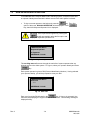
Fig 7.1: Menu displayed on the Monitor Text Channel.............................................................................7-1
Fig 7.2: Keyboard Operator List................................................................................................................7-3
Fig 7.3: Enter PIN ......................................................................................................................................7-3
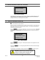
Fig 7.2: Sign On Confirmed ......................................................................................................................7-4
Fig 7.4: Sign-Off Operator.........................................................................................................................7-4
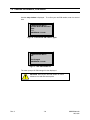
Fig 7.15: Change PIN................................................................................................................................7-5
Fig 7.15: Enter new PIN number...............................................................................................................7-5
Fig 7.16: Confirm new PIN number, again................................................................................................7-6
Fig 7.17: New PIN number OK..................................................................................................................7-6
Rev. A
x
HMXMU001056
03/16/05
CHAPTER 1:
OVERVIEW
1.1
GENERAL DESCRIPTION
MAXPRO-Net combines custom designed software with a high performing Windows
2003 Server resulting in Honeywell's Turn Key Centralized Management Console Server.
MAXPRO-Net is designed for system configuration, system management and system
monitoring of Honeywell's crosspoint matrix video switchers.
Using a system keyboard, an operator can select various cameras for display on the
available video display monitors. Where cameras have pan/tilt/lens control, the operator
can move the camera remotely via the joystick and other keys on the system keyboard.
Digital video recorders, videocassette recorders, motion detectors, and other video
processing equipment can all be incorporated into the crosspoint matrix video switching
system and can be remotely controlled from the system keyboard. External alarm inputs
can be programmed to select cameras and operate the video system automatically.
Cameras can also be electronically monitored to verify valid video signal levels. In the
event of a camera failure, the system can automatically manage, respond to, and record
the failure.
External equipment to the matrix video switching system can also be controlled using
auxiliary control output circuits. For example, electric door latches or a boom-gate
control could all be available directly from the system keyboard. The MAXPRO-Net
Crosspoint Matrix Video Switching System has been designed to cater to a large variety
of applications, including your own specific system requirements.
Rev. A
1-1
HMXMU001056
03/16/05
1.2
SYSTEM KEYBOARDS
The system keyboard, along with text message information (available via the video
display monitors), is used by the operator to control the MAXPRO-Net Crosspoint Matrix
Video Switcher.
Depending on the size of the video system, there could be up to thirty-two (32)
keyboards connected to the system. They can all operate the system at the same time
and still be totally independent of each other. There are two types of keyboard available.
1.
The HEGS5300 enhanced keyboard.
2.
The HEGSA002 ULTRAKey keyboard.
Refer to the specific user manual for your controller.
1.3
OTHER EQUIPMENT
The MAXPRO-Net Crosspoint Matrix Switcher System incorporates a variety of subrack
equipment to perform video switching and control of the entire system. As the actual
elements of equipment used in each system can vary dramatically, it is impossible to
describe your system's exact configuration in this manual.
Your system probably contains:
1.4
•
several Video Switching Modules,
•
several Post-Text Inserter Modules,
•
many fixed (non movable) cameras,
•
several PTZ (movable) cameras with preset views,
•
several VCR/DVR and PTZ control output modules,
•
possibly PTZ and VCR/DVR Control Output Modules,
•
external Alarm Input Modules,
•
various subracks (containing modules), power supplies, and a server CPU,
•
keyboards.
ASSUMPTIONS MADE BY THIS MANUAL
To discuss the operation of the MAXPRO-Net, we have assumed that your video system
has at least:
Rev. A
•
1 x keyboard, and
•
post-text insertion on at least one video display monitor.
1-2
HMXMU001056
03/16/05
1.5
CONVENTIONS USED IN THIS MANUAL
During the course of this manual, icons and examples are used, wherever possible, to
help illustrate certain points.
1.5.1
Keystrokes
Actual keys, used on the keyboard to perform certain functions, will be represented in
our examples, by icons of the respective keys.
1.6.2
•
for example,
•
or
.. represents the '0' key,
.. represents the 'Alarm Clear' key.
Numerical Range
The video system consists of numerous video input and output channels. As such, the
icon, Ù, within brackets, will be used to represent the permitted range for numerical
selection.
•
1.6.3
for example, (01 Ù 99) represents the permitted numerical range as 01 to 99,
Points to Take Note of
Points that you should be aware of will be highlighted to you in the form of a box as
shown below.
NOTE: You should pay attention to points highlighted in
paragraphs like this.
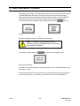
There will be areas (control of cameras, monitors, and so on) in the video system that
are restricted to some operators. Such areas, although discussed in this manual, will be
preceded by the message:
,
Rev. A
Access denied to some operators
1-3
HMXMU001056
03/16/05
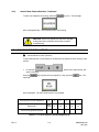
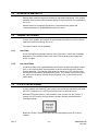
1.6.4
Monitor messages
Every monitor can display, in its text message window, the current time/date, camera
description and operator name. These parameters would be defined during the setting
up of the system's configuration.
In addition to these, other messages that report alarm conditions or system status will
also be displayed. These special messages will also appear in the text message
window, usually above the normal text messages mentioned earlier.
These special messages will be presented in this manual as the following icon:
1.6
MANUFACTURER'S NOTE
If you are experiencing any difficulties with your MAXPRO-Net Crosspoint Matrix Video
Switching System, or may have some useful information to relate back to us, kindly
contact your local distributor.
Our distributors are very carefully selected. They are provided with complete technical
support and training to ensure the highest possible standard of service.
1.7
Rev. A
ACKNOWLEDGEMENTS
•
WINDOWS
Registered trademark of the Microsoft Corporation
•
SMARTEXT
Trademark of Honeywell, Inc
•
FLASHBACK
Trademark of Honeywell, Inc
•
MAXPRO SYSTEMS AND FACE LOGO
1-4
Registered trademark of Honeywell
HMXMU001056
03/16/05
CHAPTER 2:
GETTING STARTED
2.1
ENTERING YOUR SELECTION NUMBERS
HOW AND WHY?
For nearly all keyboard operations discussed in this manual, an associated numeric
entry must be made. For example, when selecting a camera or setting the dwell for a
scan sequence.
The required number is typed in, using the SELECTION PAD on the keyboard. When
the number entered is shorter in length than expected (that is, less digits than expected),
then the
key must be pressed to indicate that the number entered is complete.
An Example:
If the maximum Camera Number used on the system is, as an example, Camera 20, the
system would then always expect 2 digit camera numbers to be entered in selecting any
camera.
To select camera 19, the operator must press the following keys:
If you wish to select camera 1, the operator must press:
As an alternative:
will also select camera 1.
In this case, as the required number of digits was pressed, the
required.
key is not
When there are less than ten possible selections (that is, 0 Ù 9), a single digit is pressed
to make the selection.
Rev. A
2-1
HMXMU001056
03/16/05
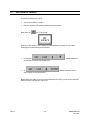
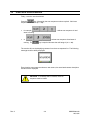
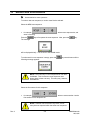
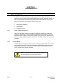
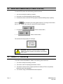
2.2
SELECTING A MONITOR
NOTE: To change the current picture on a video display
monitor, a monitor must first be selected.
Press the
key followed by the monitor number required.
•
for example,
•
.. selects monitor 6 (for a system having ten
or
or more possible monitors to select from).
.. selects monitor 3,
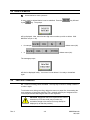
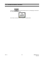
The monitor description text will now be replaced by the name of your keyboard, for
example:
NOTE: As an operator, your own name may appear
instead. This depends on the System Configuration
used.
Rev. A
2-2
HMXMU001056
03/16/05
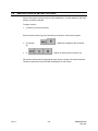
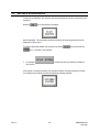
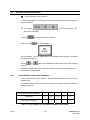
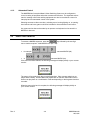
2.3
SELECTING A CAMERA
NOTE: A monitor must be selected first.
Press the
key followed by the number of the camera required.
•
for example,
•
or
or more possible cameras).
.. selects camera 25,
.. selects camera 1 (for a system having ten
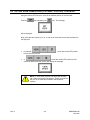
The monitor should now be displaying the new camera selected. The camera
description text should also be displayed.
NOTE: It is possible that the camera selected is not
available. In such instances, a text message will be
displayed on the monitor to explain the problem. Refer to
Chapter 9, Monitor Messages, for more information on
the displayed messages.
Rev. A
2-3
HMXMU001056
03/16/05
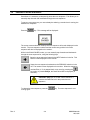
2.4
CONTROLLING A CAMERA PTZ
To operate a camera PTZ site, the following must first be true.
•
you must currently be selecting a monitor,
•
the monitor must be displaying the desired camera,
•
the desired camera must have PTZ equipment fitted.
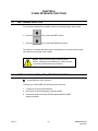
Camera pan, tilt, focus, and zoom control functions are detailed below. They are the
same on both the RD-500 and RD-530 keyboards.
PAN LEFT .. by pushing (and holding) the joystick towards the
Left. Releasing the joystick will halt the pan function.
PAN RIGHT .. by pushing (and holding) the joystick towards the
Right. Releasing the joystick will halt the pan function.
TILT UP .. by pushing (and holding) the joystick towards the Up
mark. Releasing the joystick will halt the tilt function.
TILT DOWN .. by pushing (and holding) the joystick towards the
Down mark. Releasing the joystick will halt the tilt function.
NOTE: The Tilt Up and Down functions, may be reversed,
depending on your system's configuration.
If the MANUAL-IRIS or WASH/WIPE options are fitted to the camera PTZ site, then the
following PTZ functions can also be used:
Rev. A
2-4
HMXMU001056
03/16/05
2.4.1
Other PTZ functions
The following PTZ functions may be available as well provided the keyboard being used
supports the function. Refer to your specific keyboard user manual.
•
ZOOM IN .. by pressing (and holding) the
will halt the Zoom function.
•
ZOOM OUT .. by pressing (and holding) the
will halt the Zoom function.
•
FOCUS FAR .. by pressing (and holding) the
will halt the Focus function.
•
FOCUS NEAR .. by pressing (and holding) the
key will halt the Focus function.
•
IRIS OPEN .. By pressing (and holding) the
will halt the manual-iris function.
•
IRIS CLOSE .. by pressing and (holding) the
key halt the manual-iris function.
•
WASH .. by pressing (and holding) the
will halt the wash function.
•
WIPE .. by pressing (and holding) the
halt the wipe function.
key. Releasing the
key. Releasing the
key. Releasing the
key
key
key
key. Releasing the
key. Releasing the
key
key. Releasing the
key. Releasing the
key. Releasing the
key
key will
NOTE: With the proper equipment installed, PTZ sites
can have variable speed controls for the Pan/Tilt and
Focus/Zoom functions. When a PTZ function is selected
from the keyboard, you'll have 'half' speed for the first
second. After that, 'full' speed is attained. This allows
faster movement from one point to another. It also allows
greater precision when making minor adjustments for a
proper view.
Rev. A
2-5
HMXMU001056
03/16/05
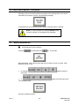
2.5
SELECTING A VCR
NOTE: A monitor must be selected first.
Press the
key, followed by the VCR number.
•
for example,
•
or
selects VCR 10,
selects VCR 4.
The monitor should now be displaying the video from the output of the VCR selected.
The VCR description text should also be displayed on the monitor.
2.6
CONTROLLING A VCR FROM THE KEYBOARD
,
Control of VCRs may be denied for some operators
The VCR control functions are listed below. They are the same for both keyboards.
To operate a VCR machine remotely from a keyboard, the following must first be true:
•
a monitor must currently be selected,
•
the monitor must be displaying the desired VCR machine,
•
the desired VCR machine must have remote control capability fitted.
Once the above is true, the following keys on the CONTROL PAD of the keyboard can
be used:
.. to begin playback.
.. to cancel playback record rewind and fast forward.
Rev. A
2-6
HMXMU001056
03/16/05
2.6 CONTROLLING A VCR FROM THE KEYBOARD, CONTINUED
.. to rewind the tape.
.. to fast-forward the tape.
.. half speed play. For some VCR's this is shuttle mode.
.. to pause playback (still-frame).
.. to begin recording.
.. to eject the tape.
.. to temporarily hide the text display on the monitor. When VCRs with
SMARTEXT are played back, the concealed text can be displayed on the
monitor again.
NOTE: Some functions of the VCR may not be available
for your system.
Rev. A
2-7
HMXMU001056
03/16/05
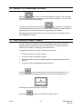
2.7
RECORDING A CAMERA
To record a camera onto a VCR:
•
you must first select a monitor,
•
then the required VCR must be selected onto the monitor,
Next press the
key. The prompt:
appears on the monitor. Now, make your camera selection, exactly as if you were
selecting the camera directly on the monitor.
•
for example,
as the video source for the current VCR.
•
or
video source for the current VCR.
.. selects camera 15
.. selects camera 3 as the
Now that the new video source has been selected by the VCR, you can control the VCR:
Record function, text function, and so on.
Rev. A
2-8
HMXMU001056
03/16/05
2.8
AUXILIARY DEVICES AND MULTIPLEXERS
Various other types of devices such as video multiplexers, or motion detectors and video
printers can also be selected.
To select a device;
•
a monitor must first be selected;.
Press the desired device type key followed by the number of the device required.
•
for example,
(5),
•
or
.. selects the multiplexer device number
.. selects an auxiliary device number (10).
The monitor should now be displaying the video from the output of the device selected.
The device description text should also be displayed on the monitor.
Rev. A
2-9
HMXMU001056
03/16/05
NOTES:
Rev. A
2-10
HMXMU001056
03/16/05
CHAPTER 3:
USING SCAN SEQUENCES
3.1
WHAT IS A SCAN SEQUENCE?
A Scan Sequence is a list of camera selections. This camera list, or scan sequence, is
used to automatically display every camera in the sequence on a specific monitor. Each
camera selection will remain displayed for a specified duration defined by the 'Dwell
Time' setting of each scan sequence.
When the scan sequence reaches its end, it wraps back around and starts again,
creating an endless sequence of pre-defined camera selections.
A scan sequence can have up to 99 separate camera selections (called Entries). A total
of 99 separate scan sequences can be created for use within the system.
When required, one of several scan sequences can be run on a monitor. When the
same scan sequence is being run on more that one monitor at the same time, the
displayed camera selections are made in synchronous.
NOTE: Camera selections or entries in scan sequences
can (within the limitations of source grouping for that
monitor) be in any order.
3.1.1
What is a Guard Tour?
A guard tour is a scan sequence that does not wrap around when it reaches the end.
When a guard tour is run, it always begins from the first entry. After the last camera
entry has been displayed, the guard tour will halt automatically.
During commissioning, scan sequences are flagged to operate as guard tours. In all
other respects, they are considered as scan sequences.
Rev. A
3-1
HMXMU001056
03/16/05
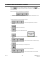
3.2
STARTING A SCAN SEQUENCE
Firstly, a monitor must be selected.
Press the
key, followed by the scan sequence number required. Valid scan
sequence numbers are (01 Ù 99).
•
for example,
starts it running.
•
or
.. selects scan sequence 21 and
.. selects scan sequence 5 and starts it
running. The
key is required because the valid range is (01 Ù 99).
The monitor will now be displaying cameras from the scan sequence list. The following
message would be briefly displayed.
Every time the scan sequence selects a new camera, the associated camera description
text will also be displayed.
CAUTION: To manually select a camera, the scan
sequence must be halted.
Rev. A
3-2
HMXMU001056
03/16/05
3.3
HALTING A SCAN SEQUENCE
To halt a scan sequence, the operator must have selected the monitor running that scan
sequence.
When the
key is pressed, the message:
will be displayed. The last camera selection made by the scan sequence will remain
displayed on the monitor.
To restart a previously halted scan sequence, press the
key followed by the
key. A number is not required.
•
for example,
this monitor.
.. restarts the last scan sequence halted for
If the monitor is already running a scan sequence before manually selecting a camera
(or a different scan sequence), then the following message appears:
Rev. A
3-3
HMXMU001056
03/16/05
3.4
PAUSING A SCAN SEQUENCE
Sometimes, it is necessary to temporarily pause the scan sequence. This allows you to
manually step forwards and backwards through the scan sequence.
To pause a scan sequence, you must already be selecting a monitor that is running the
desired scan sequence.
Press the
key. This message will be displayed:
The current camera selection made by the scan sequence will remain displayed on the
monitor. The scan sequence number and the current entry position in the scan
sequence will also be displayed on the monitor.
While in the 'SCAN PAUSED' mode, you can manually step forwards and backwards
through the scan sequence list, using the following keys:
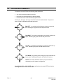
Steps the scan sequence forward to the NEXT selection in the list. This
camera is then displayed on the monitor.
Steps the scan sequence backwards to the PREVIOUS selection in the
list. The camera is then displayed on the monitor. When the sequence
reaches Entry 1, if it is stepped back once more (by pressing the
key again), to pseudo Entry 0, the Dwell Period will be displayed (in
seconds).
CAUTION: Entry 0 is not a valid camera selection; it
contains the Dwell Period for that particular scan
sequence.
To release the scan sequence, press the
running again.
Rev. A
3-4
key. The scan sequence is now
HMXMU001056
03/16/05
3.5
MAKING A NEW SCAN SEQUENCE
,
Access denied to some operators
To make a new scan sequence, a monitor must first be selected.
Select the NEW scan sequence.
•
for example,
starts it scanning.
Press the
The message
.. selects scan sequence 20, and
key to first pause the scan sequence. Now, press the
key.
will be displayed briefly. You are now in 'SET SCAN' mode.
To make sure this scan sequence is empty, press the
following message appears:
key several times until the
NOTE: The First Entry in a scan sequence list can never
be deleted. This is because a scan sequence must
always have at least one entry. This entry may, however,
be redefined.
Select the first camera for this sequence.
•
for example,
first camera in scan sequence 20.
.. selects camera number 2 as the
NOTE: Cameras can be stored in any order, and as
many times as required within the same scan sequence.
Rev. A
3-5
HMXMU001056
03/16/05
3.5 MAKING A NEW SCAN SEQUENCE, CONTINUED
Before the next camera can be selected, we have to make room in the sequence list.
Press the
key to insert a new entry into the scan sequence. Press
to this NEW ENTRY.
to move
Now the next camera for this sequence can be selected.
•
for example,
the second camera in scan sequence 20.
.. selects camera number 12 as
The entire procedure can be summarized as follows:
•
.. selects scan sequence 20, and starts it
scanning.
•
pauses scan sequence 20.
•
puts you in the 'SET SCAN' mode.
•
press this key several times until the
message
appears.
•
.. selects camera number 2 as the first entry of
scan sequence 20.
•
creates a new entry for scan sequence 20.
•
.. moves you to the second entry of scan sequence 20.
•
.. selects camera number 12 as the second
entry of scan sequence 20.
Rev. A
3-6
HMXMU001056
03/16/05
3.5 MAKING A NEW SCAN SEQUENCE, CONTINUED
•
creates another new entry for scan sequence 20.
•
moves you to the third entry of scan sequence 20.
•
.. selects camera number 29 as the third entry
of scan sequence 20.
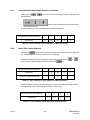
By now, the following cameras are present in scan sequence 20:
Entry position in Scan Sequence
1
2
3
Camera No.
2
12
29
Table 3.1: Entry Positions In Scan Sequence 20
Continue until all the desired cameras in the scan sequence have been entered.
To start the scan sequence running, press the
key once. The message:
will be displayed briefly. Scan sequence 20 is now running.
CAUTION: Some scan sequences cannot be changed
as they have been predefined and locked at system
commissioning.
Rev. A
3-7
HMXMU001056
03/16/05
3.6
EDITING A SCAN SEQUENCE
,
Access denied to some operators
To edit a scan sequence it is necessary for the desired sequence to be selected to the
operator's monitor.
for example,
.. selects scan sequence 20,
and starts it scanning.
Press the
key to pause the scan sequence.
Now, press the
key. The message:
will be displayed. The 'SET SCAN' mode is now enabled and the operator can begin to
edit the scan sequence.
Use the
entry list.
and
keys to move backwards and forwards in the scan sequence
When the required entry position has been selected, then one of the following three
operations can be performed:
3.6.1
Overwrite With A New Camera Selection
Simply make another camera selection. This will overwrite the current entry in the scan
sequence list.
For example suppose that the second entry needs to be camera number 25 instead of
camera number 12.
Entry position in Scan Sequence
1
2
3
4
5
Camera No.
2
12
29
14
17
Entry position selected
*
Table 3.2: Entry Positions In Scan Sequence 20 Before Overwriting.
Rev. A
3-8
HMXMU001056
03/16/05
3.6.1
Overwrite With A New Camera Selection, Continued
Simply use the
following keys:
or
keys to move to the second entry position, and press the
•
selects camera number 25 as the second entry
in scan sequence 20.
Camera number 12 is now overwritten by the camera number 25.
Entry position in Scan Sequence
1
2
3
4
5
Camera No.
2
25
29
14
17
Table 3.3: Entry Positions In Scan Sequence 20 After Overwriting.
3.6.2
Delete This Camera Selection
Pressing the
key will remove this camera selection entry from the scan sequence
list. All following entries will move down one to fill the gap.
If camera number 29 is to be removed from scan sequence 20, use the
keys to move to the third entry position and press the
or
key.
Entry position in Scan Sequence
1
2
3
4
5
Camera No.
2
25
29
14
17
Current entry position selected
*
Table 3.4: Entry Positions In Scan Sequence 20 Before Deletion.
Camera numbers fourteen (14) and seventeen (17) at entry positions three (3) and four
(4) respectively, moves down one entry position to fill the gap.
Entry position in Scan Sequence
1
2
3
4
Camera No.
2
25
14
17
Table 3.5: Entry Positions In Scan Sequence 20 After Deletion.
Rev. A
3-9
HMXMU001056
03/16/05
3.6.3
Insert A New Camera Selection
Pressing the
key will insert a new selection entry into the scan sequence at the
current entry position. All entries following this position will be shifted up once, to make
room.
The following 3 tables illustrate what happens when camera number 10 is inserted into
entry position (3) of the scan sequence.
Use the
or
keys to move to the third entry position of the scan sequence.
Entry position in Scan Sequence
1
2
3
4
5
Camera No.
2
25
29
14
17
Current entry position selected
*
Table 3.6: Entry Positions In Scan Sequence 20 Before Insertion.
Now, press the
key.
Entry position in Scan Sequence
1
2
3
4
5
6
Camera No.
2
25
29
29
14
17
Current entry position selected
*
Table 3.7: Entry Positions In Scan Sequence 20 After Pressing The
Key.
To replace entry position 3 with camera number 10, press the following keys:
•
.. inserts camera number 10 as the third entry of
the scan sequence.
•
Entry position in Scan Sequence
1
2
3
4
5
6
Camera No.
2
25
10
29
14
17
Table 3.8: Inserting Camera No 10 Into Entry Position 3.
Rev. A
3-10
HMXMU001056
03/16/05
3.6.3
Insert A New Camera Selection. Continued
To start scan sequence 20 running, press the
key once. The message:
will be displayed briefly. Scan sequence 20 is now running.
CAUTION: Some scan sequences cannot be changed
as they have been predefined and locked at system
commissioning.
3.7
CHANGING THE DWELL PERIOD
,
Access denied to some operators
To edit a dwell period it is necessary for the desired scan sequence to be running on the
monitor.
•
for example,
starts it scanning.
Press the
message:
.. selects scan sequence 20, and
key to pause the scan sequence. Now, press the
key. The
will be displayed. The 'SET SCAN' mode is now enabled.
Entry position in Scan Sequence
0
1
2
3
4
5
Camera No.
dwell
period
2
25
12
29
14
Current entry position selected
*
Table 3.9: The Scan Sequence List Showing Entry (0).
Rev. A
3-11
HMXMU001056
03/16/05
3.7 CHANGING THE DWELL PERIOD, CONTINUED
Use the
key to move backwards in the scan sequence. Continue pressing the
key until the beginning of the scan sequence list is reached (that is, before Entry
(1)).
Entry position in Scan Sequence
0
1
2
3
4
5
Camera No.
dwell
period
2
25
12
29
14
Current entry position selected
*
Table 3.10: Using The
Key To Move To Entry (0).
The message:
will be displayed briefly, together with the current dwell setting (in seconds). The valid
dwell period is (01 Ù 99) seconds.
Now, enter the new dwell period:
•
for example,
•
or
.. new Dwell = 15 seconds.
.. new Dwell = 3 seconds.
To start the scan sequence running again, press the
key once. The message:
will be displayed briefly. Scan sequence 20 is now running.
Rev. A
3-12
HMXMU001056
03/16/05
3.8
INCREASING THE DWELL FOR ONE CAMERA
As there is only one Dwell Period setting for the entire scan sequence camera selection
list, the method of varying the dwell period for one specific camera is to enter that
camera selection two or more times (consecutively) into the scan sequence list.
This method allows individual cameras to remain displayed for two, three, or more
multiples of the current dwell period.
Rev. A
3-13
HMXMU001056
03/16/05
NOTES:
Rev. A
3-14
HMXMU001056
03/16/05
CHAPTER 4:
USING MACROS
4.1
WHAT IS A MACRO?
A MACRO is a stored recording of a series of keystrokes made by an operator on a
keyboard. This recording can be PLAYED BACK by the operator whenever required. It
will mimic the operator by automatically making those same keystroke actions again.
Macros can be used to automate the system in three ways;
4.1.1
•
Salvo camera selections
•
Camera walks
•
Automated control
Salvo Camera Selections
Salvo is the automatic selection of multiple cameras from a simple key press action.
Unlike scan sequences, all of the cameras are displayed at the same time across the
designated video monitors. Salvos would be used to give a panoramic overview of an
area, for example, adjacent perimeter alarm zones or viewing a secure area (or level) in
a building.
4.1.2
Camera Walks
Camera walks are commonly used to survey an area using a PTZ camera. The control
actions applied to the PTZ camera are played back in real-time (at the same rate that
they were recorded). This means that the camera follows the same path across the
scene of view as was originally recorded.
NOTE: A PTZ camera view recall would be used first in
the camera walk to set a known start position.
Rev. A
4-1
HMXMU001056
03/16/05
4.1.3
Automated Control
The MAXPRO-Net Crosspoint Maxtrix Video Switching System can be configured to
control a variety of equipment other than cameras and monitors. The keyboard actions
used to manually control this auxiliary equipment can also be recorded in a macro for
later play back for automated control of the system.
Selecting cameras to video recorders, activating record, turning lighting on, or opening
door latches and boom gates could all be included in one automated control macro.
Any system action that can be made by an operator at a keyboard can be stored in a
MACRO for later use.
4.2
EXECUTING A MACRO
To execute a MACRO sequence, press the
key followed by the two-digit
macro number required. Valid MACRO's are (00 Ù 99).
•
for example,
•
or
.. executes MACRO (65).
.. executes MACRO (00).
If the macro has been defined, the following message will display briefly on your current
monitor:
The macro will now play back the recorded keystrokes. Salvo camera selections are
played back instantly. Camera Walks are played back in real-time. Automated control
actions can play back as a combination of the two depending on the keypress functions
recorded.
When the macro play back is complete, the following message will display briefly on
your current monitor:
Rev. A
4-2
HMXMU001056
03/16/05
4.2 EXECUTING A MACRO, CONTINUED
Although a macro can be executed by any operator from any keyboard, it can only be
executed by one person at a time. If the following message;
is displayed, then you must wait until the operator using that macro is finished.
NOTE: If a macro sequence is executed without having
a monitor selected, no messages will be displayed.
4.3
MAKE A NEW MACRO
,
Access denied to some operators
Press the
key followed by the
key. The prompt:
will be displayed. Now, select the two-digit macro number you wish to create. Valid
MACRO's are (00 Ù 99).
•
for example,
macro (65).
•
or
.. begins recording
.. begins recording macro (00).
The message prompt:
will then be displayed briefly.
Rev. A
4-3
HMXMU001056
03/16/05
4.3 MAKE A NEW MACRO, CONTINUED
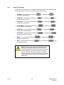
The system will now begin recording operator keyboard actions. These may be recorded
in a REALTIME mode whereupon running of the macro the operator actions will be
played back with the same timing with which they were recorded, or in AUTO-TIMING
mode whereupon operator actions will be played back automatically timed. The
recording mode may be toggled during recording by pressing the
key. The
prompt:
or
will then be displayed briefly to indicate the current mode.
NOTE: To redefine a macro that has been used
previously, it must first be deleted. Refer to the following
section DELETE A MACRO.
To end the recording, press the
key again. The message prompt:
will be displayed briefly.
Your macro is now defined with the recorded keystrokes. Now, test the MACRO to see if
it executes correctly.
The newly defined macro will be saved back onto disk automatically by the system after
30 seconds of inactivity or by initiating a ’Save Now’ function from System Macros.
Rev. A
4-4
HMXMU001056
03/16/05
4.4 DELETE A MACRO
,
Access denied to some operators
A macro must be deleted before it can be redefined. Press the
by the
key followed
key. The prompt:
will be displayed. Now, select the two-digit macro number you wish to delete. Valid
MACRO's are (00 Ù 99).
•
for example,
•
or
.. deletes macro (65).
.. deletes macro (00).
The message prompt;
will then be displayed briefly. Your macro is now deleted. It is ready to be defined
again.
4.4
CAN I EDIT A MACRO?
NO. A macro recording cannot be edited. The only way to correct or modify a macro is
to make it again.
To minimize errors during recording, design the macro on paper first, documenting the
exact sequence of keystrokes required. Then, manually execute your designed macro
on the keyboard while watching the effect of each keystroke.
CAUTION: Remember that some keystrokes like camera
selections (or PTZ view recall) may not make any
noticeable change to the monitor as it may already be
displayed (or at that view position).
Rev. A
4-5
HMXMU001056
03/16/05
NOTES:
Rev. A
4-6
HMXMU001056
03/16/05
CHAPTER 5:
MANAGING ALARMS
5.1
WHAT ARE ALARMS?
ALARMS are usually external inputs to the crosspoint matrix video switching system.
These inputs are watched continuously by the equipment. If a change in alarm state
occurs on an alarm input, the system operators can be prompted immediately and
automatic selection of cameras and VCRs, and so on, can also occur.
The automatic action taken for any given alarm input is programmed at commissioning
and therefore cannot be changed by an operator. However, through the use of the
MENU SYSTEM (Chapter 8), it is possible to disable and re-enable an alarm input. This
is required for night/day system operation, where some alarms must be ignored during
the daytime hours.
As well as external alarm inputs, other internal system alarms can also occur. They are
as follows:
•
Camera fail alarms,
•
PTZ site fail alarms,
•
PTZ site tamper alarms,
•
VCR alarms,
•
Other device alarms,
•
General failure.
When an alarm state is generated:
•
a flashing text prompt is displayed (after approx. 0.5 second). This prompt actually
describes that specific alarm.
•
automatic control of the system is activated as defined at the time of commissioning.
This may be as simple as selecting a relevant camera onto a video monitor or may
be causing a camera to be automatically recorded.
WARNING: The time/date that is displayed when an
alarm activates is the time that the alarm occurred.
Rev. A
5-1
HMXMU001056
03/16/05
5.2
EXTERNAL ALARM INPUTS
External alarm inputs are usually hard wired into the subrack equipment. They include
perimeter security alarms, PIR movement detectors, intercom alarms, door state alarms,
and so on.
External alarms are sometimes monitored by a separate security system and
communicated back to the MAXPRO-Net system for action.
5.3
CAMERA FAIL ALARMS
In some video systems, the cameras are automatically monitored to check for camera
malfunction and/or cut-cabling, and so on.
Two types of alarms can be generated:
5.3.1
Lost Video
A Lost Video alarm is generated when the video signal from a camera has completely
disappeared. The possible causes of this alarm could be blown power-supply fuse
and/or cut-cable.
5.3.2
Low Level Video
A Low-Level Video alarm is generated when the picture level decreases below a preset
point. The low picture level must be present for several seconds before the alarm is
actually generated. This detection delay allows for auto-iris lag. PTZ units can move
across dark scenes without generating false alarms. The possible causes of this alarm
are; the front of the lens is covered, the scene lighting is low, or the camera or lens
maybe faulty.
5.4
PTZ SITE FAILED ALARMS
In video systems, the camera PTZ site receivers are continuously monitored, even while
the site is not being used. If a PTZ site should fail, then an alarm will occur.
While the PTZ site has failed, it is still possible to view a picture from this camera. If,
however, the PTZ controls are used, then the operator is again prompted with the
following message;
When the PTZ site is repaired, the alarm will clear automatically and PTZ control is
restored.
Rev. A
5-2
HMXMU001056
03/16/05
5.5
PTZ SITE TAMPER ALARMS
To protect a camera PTZ site from unauthorized access, the tamper alarm input would
be used. A tamper alarm is LATCHING, so once activated, it can only be cleared from
the keyboard by an operator.
5.6
VCR ALARMS
VCR alarms are commonly used to detect END OF TAPE or NO RECORD status
conditions and report these to the operator. The VCR alarm would be cleared
automatically by rectifying the reported condition. VCR alarms can also be cleared from
a keyboard.
5.7
OTHER DEVICE ALARMS
Multiplexers and other devices that are under the control of the system can also have
associated alarms. For video motion detectors, this could be a movement alarm; for a
video printer, it may be a device busy or out of paper alarm.
Similar to VCR alarms, they are used to help automatically manage the video system.
5.8
THE ALARM STACK
Whenever an alarm becomes active, it is placed onto the alarm stack. If several alarms
become active at the same time, they will all be placed onto the alarm stack accordingly.
The purpose of the alarm stack is to cycle between the currently active alarms, redisplaying their particular text messages and re-executing their specific automatic
camera selections (and other control actions).
The alarm stack will pause for a pre-defined period between each active alarm recorded
on the stack.
Rev. A
5-3
HMXMU001056
03/16/05
5.9
STEPPING THROUGH THE ALARM STACK
CAUTION: You must currently be selecting the monitor
that is displaying the flashing alarm messages.
On the HEGS5300 enhanced keyboard, pressing the
key will manually force
the alarm stack to cycle to the next active alarm. Immediately, the next alarm will be
displayed on the monitor.
The alarm stack will still automatically cycle after the usual pause period.
5.10
CLEARING AN ALARM
When an alarm is manually cleared from a keyboard, it is removed from the alarm stack
so it will not continue to be displayed again. With the exception of LATCHING alarms,
the manually cleared alarm is still active and remains so until it physically returns to its
normal state. Once this has happened, its next activation will be detected again.
CAUTION: You must currently be selecting the monitor
that is displaying the flashing alarm messages.
Press the
message prompt;
key to clear the currently displayed alarm. After a short pause the
will be displayed. Immediately, that alarm is removed from the stack and the next alarm
is displayed on the monitor.
When ALL alarms have been cleared, the text display on the monitor will return to
normal.
CAUTION: While the flashing alarm text is displayed on
the monitor, none of the normal text messages will be
displayed.
Rev. A
5-4
HMXMU001056
03/16/05
5.10 CLEARING AN ALARM, CONTINUED
key while the selected monitor is not displaying an active alarm
Pressing the
will display the message prompt;
even if there are still active alarms displayed on another monitor.
Rev. A
5-5
HMXMU001056
03/16/05
NOTES:
Rev. A
5-6
HMXMU001056
03/16/05
CHAPTER 6:
OTHER KEYBOARD FUNCTIONS
6.1
FAST CAMERA SELECTION
To scroll quickly between the available cameras, the following keys may be used;
•
Press the
key to select the NEXT camera.
•
Press the
key to select the PREVIOUS camera.
The selection of cameras with these keys is dependent on the current monitor being
used and the access level of the operator.
NOTE: These keys also apply to VCRs and other
devices. When the current selection is a VCR, the next
(or previous) VCR would then be selected.
6.2
SETTING A NEW CAMERA VIEW (PTZ PRESET POSITION)
,
Access denied to some operators
To program a camera VIEW, the following must first be true:
1. a monitor must currently be selected,
2. the monitor must be displaying the desired camera,
3. the desired camera must have PTZ equipment fitted with VIEW
(preset) capability.
Rev. A
6-1
HMXMU001056
03/16/05
6.2 SETTING A NEW CAMERA VIEW (PTZ PRESET POSITION), CONTINUED
Using the camera PTZ functions, move to the desired position of the new view.
Press the
key followed by the
key. The message:
will be displayed.
Now, press the view number (0 Ù 9). A total of ten views per camera are possible from
the keyboard.
•
for example,
for this camera as view 5.
•
or
.. stores the current PTZ position for this
camera as VIEW 0 and the monitor will display the message:
.. stores the current PTZ position
NOTE: In some video systems, two digit view numbers
(00Ù 99) would need to be entered. Usually only the first
ten (0Ù 9) are manually available to the keyboard
operator.
Rev. A
6-2
HMXMU001056
03/16/05
6.3
RECALLING A CAMERA VIEW (PTZ PRESET POSITION)
To recall a PTZ camera view the following must first be true.
1. you must currently be selecting a monitor,
2. the monitor must be displaying the desired camera,
3. the desired camera must have PTZ equipment fitted with VIEW (preset) capability.
Press the
key followed by the view number required. The range of valid views
are (0 Ù 9). A total of ten views per camera PTZ site are available.
•
for example,
•
or
.. selects camera view 5,
.. selects camera view 0.
The monitor will briefly display the message:
CAUTION: VIEW (0) is commonly used as a HOME
position, to quickly reposition the camera to the desired
static scene.
6.4
CAMERA PTZ FLASHBACK
To use the camera FLASHBACK feature, the following must first be true.
1. You must currently be selecting a monitor,
2. The monitor must be displaying the desired camera,
3. The desired camera must be a high-speed dome camera (PT-720 or equivalent)
fitted with preset view capability,
4. You must be using an HEGS5300 enhanced keyboard.
Rev. A
6-3
HMXMU001056
03/16/05
6.4 CAMERA PTZ FLASHBACK, CONTINUED
Press the
key to move to the first FLASHBACK position. This is similar to
recalling a preset view, although the prior position is first remembered. The dome PTZ
can be operated manually as required.
key. Now your current position
To go back to the prior position, press the
is remembered and the prior position is recalled. The FLASHBACK feature allows two
separate targets to be followed using the one high-speed dome camera.
Recalling a preset view will first cause your current position to be remembered as the
next FLASHBACK position.
6.5 SELECTING AN ALTERNATE CAMERA
For every camera, it is possible to have a pre-defined alternate camera. Often the
alternate camera is a PTZ camera and view recall position, or simply another fixed
camera giving a different viewing angle of the same scene.
To display an alternate camera, the following must first be true.
1. You must currently be selecting a monitor,
2. The monitor must be displaying a camera,
3. The camera must have been commissioned with a pre-defined alternate camera
selection.
4. You must be using a HEGS5300 enhanced keyboard.
Press the
key to select the alternate camera (and view recall position). The
monitor should now be displaying the alternate camera. If the message prompt;
was displayed, no alternate camera is available.
Pressing the
Rev. A
key again will re-select the original camera.
6-4
HMXMU001056
03/16/05
6.5
HIDING DISPLAYED TEXT
The displayed monitor text is used to identify the selected camera, present current
time/date and other prompt messages. Sometimes, it is required that the displayed text
be turned-off (or hidden) allowing the total picture area to be viewed.
To hide the displayed text, the following must first be true.
•
You must currently have a monitor selected
Press the
key to remove the text from the monitor. You can manually control
the selected PTZ camera as required. The text will remain hidden.
By selecting another camera, moving to another monitor or pressing the
again, the text display will be restored.
key
If the monitor supports SMARTEXT a played-back recording (from a VCR) can have it's
concealed text information revealed.
6.6
REVEALING SMARTEXT
On some video systems, it is necessary to record a camera with its identification and
time/date text information remains concealed, so the maximum recorded picture area is
maintained.
SMARTEXT is used to encode the text information (as data) into the recorded video
signal without affecting the displayed picture. During playback, the operator has the
choice to either reveal or hide the encoded text information.
For SMARTEXT playback, the following must first be true.
•
You must currently be selecting a monitor that supports SMARTEXT decoding.
•
You must be playing-back a recording which was encoded with SMARTEXT
information.
The function of the
Rev. A
key is then extended to include SMARTEXT decoding.
•
The FIRST time the key is pressed the normal monitor text display is hidden. This is
the same as before.
•
The SECOND time the key is pressed the encoded SMARTEXT information (in the
video signal) will be revealed and displayed on the monitor.
•
The THIRD time the key is pressed the normal monitor text display will be restored
and the SMARTEXT information will be concealed.
6-5
HMXMU001056
03/16/05
6.7 REVEALING SMARTEXT, CONTINUED
By selecting another camera or moving to another monitor, the normal monitor text
display will be restored and the SMARTEXT information will again be concealed.
CAUTION: SMARTEXT is only available on specific
video systems that are designed to support this feature.
Rev. A
6-6
HMXMU001056
03/16/05
CHAPTER 7:
THE TEXT CHANNEL MENU SYSTEM
7.1
WHAT IS THE TEXT CHANNEL MENU SYSTEM?
The MAXPRO-Net generates the Menu system using the Text Lines displayed on the
Monitor, which enables the Operator to perform Sign in, Sign Off, Change PIN
operations.
<MAXPRO-Net Menu>
MAXPRO-Net V5.2
SIGN-ON OPERATOR
04MAR2005 11:50:29
Fig 7.1: Menu displayed on the Monitor Text Channel
The Three Options of the Text Channel Menu System,
7.1.1
•
SIGN-ON OPERATOR
•
SIGN-OFF OPERATOR
•
CHANGE PIN
Accessing the MENU SYSTEM
To access the MENU SYSTEM, press the
key on the keyboard. Text channel
of the current keyboard monitor should display the menu.
If a monitor is not currently selected, the menu will appear on your last selected monitor.
7.1.2
•
Only one operator (that is, keyboard) can have access to the Menu System at any
one time.
•
If more than one keyboard is selecting the monitor, the Menu System CANNOT be
accessed. Move to another monitor prior to using the Menu System.
•
If the monitor is running a scan sequence, then selecting the Menu System will
HALT the scan sequence. Exiting the Menu System will NOT restart the scan
sequence; this must be done manually.
Exiting the MENU SYSTEM
To exit the MENU SYSTEM, press the
key again. The menu display will be
replaced by the original camera selection. You can exit from the MENU SYSTEM at any
time, from any menu level.
Rev. A
7-1
HMXMU001056
03/16/05
7.2
MAKING SELECTIONS FROM THE MENU
•
When the Menu is selected, the First Option of the Menu ’SIGN-ON OPERATOR’ will
be displayed on the Text Channel.
Pulling the joystick towards you will move
down the menu to the Second Option ’Sign
Off Operator.’
Pushing the joystick away from you will move
up the menu to First option ’Sign On
Operator.’
By making several joystick actions, you can navigate to other options of the Menu.
Pushing the joystick RIGHT will select the
displayed Menu Option and then display the
next corresponding Menu Level.
Pushing the joystick LEFT will remove your
current Menu and return you to the previous
Menu Level.
NOTE: The
and
keys on the SELECTION PAD of
the keyboard will also move up and down the Menu. Pressing
the
key will select the Menu Option, and display
the next corresponding Menu Level.
Rev. A
7-2
HMXMU001056
03/16/05
7.3
SIGN-ON KEYBOARD OPERATORS
In the MAXPRO-Net Crosspoint Matrix Video Switching System, a keyboard must have
an operator identity associated with it before access to the video system is allowed.
•
To sign-on a new operator to the keyboard, press the
key. Then, first
option of the menu ’SIGN-ON OPERATOR’ will be displayed. Press
Key, then Valid ‘Keyboard Operator List' is displayed.
CAUTION: If the keyboard was signed-off, pressing the
key will automatically select the first option and
display the 'Keyboard Operators List.'
<MAXPRO-Net Menu>
Keyboard Operator
01-Operator1
04MAR2005 11:50:29
Fig 7.2: Keyboard Operator List
This scrolling menu will traverse through the entire list of system operators that are
allowed access to the video system. To sign-on, select your operator identity and Press
Key.
Each system operator is given a PIN (Personal Identification Number). Having selected
your operator identity, you will be prompted to enter your PIN.
<MAXPRO-Net Menu>
Enter PIN
****
04MAR2005 11:50:29
Fig 7.3: Enter PIN
Enter your four digits PIN followed by the
key. If sign-on is successful, the
menu will exit displaying the original camera on the monitor. The following message is
displayed briefly:
Rev. A
7-3
HMXMU001056
03/16/05
7.3 SIGN-ON KEYBOARD OPERATORS, CONTINUED
SIGN-ON CONFIRMED
04MAR2005 11:50:29
Fig 7.2: Sign On Confirmed
If the keyboard is already signed-on by another operator, you should still sign-on to the
system using your own operator identity. Every operator has his or her own access
privileges necessary for controlling the video system.
7.4
SIGN-OFF KEYBOARD OPERATORS
,
Access denied to some operators.
Different operators have different levels of system access; therefore it is good practice to
always sign-off when you've finished using the system. This reduces the probability of
tampering by unauthorized users.
Press the
key to display the Main Menu. Select the second Option ‘SIGN-OFF
OPERATOR.’ An entry window will be displayed asking you to confirm your intent to
sign-off.
<MAXPRO-Net Menu>
Sign-OFF Operator
Press ENTER to Confirm
04MAR2005 11:50:29
Fig 7.4: Sign-Off Operator
Press the
system.
Pressing the
off window.
key to sign-off. The keyboard operator is now signed-off from the
key or moving the joystick LEFT will cancel and remove the sign-
The keyboard is now disabled. All keys (except for the
key) will be ignored.
CAUTION: In systems that are not using the individual
operator environment, the keyboards remain signed-on
all the time. A default operator is assigned to the
keyboards and the ability to sign-off is denied.
Rev. A
7-4
HMXMU001056
03/16/05
7.5
CHANGE PIN NUMBER
,
Access denied to some operators
To change a PIN, the operator must be signed onto the keyboard. From the main
menu, highlight and select the item 'Change PIN number.'
WARNING: If you do not have the correct access
privileges, the message, 'ACCESS DENIED' will be
flashed on the monitor.
<MAXPRO-Net Menu>
MAXPRO-Net V5.2
CHANGE PIN
04MAR2005 11:50:29
Fig 7.15: Change PIN
<MAXPRO-Net Menu>
Enter New PIN
****
04MAR2005 11:50:29
Fig 7.15: Enter new PIN number
An entry window is displayed requesting the new PIN. Enter the new four-digit PIN
number for this operator.
Rev. A
7-5
HMXMU001056
03/16/05
7.5 CHANGE PIN NUMBER, CONTINUED
Another entry window is displayed. To confirm your new PIN number, enter it a second
time.
<MAXPRO-Net Menu>
Confirm New PIN and Press
Enter
****
04MAR2005 11:50:29
Fig 7.16: Confirm new PIN number, again
<MAXPRO-Net Menu>
OK
PIN Changed
04MAR2005 11:50:29
Fig 7.17: New PIN number OK
The menu prompt 'OK PIN changed' is then displayed.
CAUTION: Record your new PIN number for future
reference in a safe and secure place.
Rev. A
7-6
HMXMU001056
03/16/05
CHAPTER 8:
MESSAGE PROMPTS
8.1
INTRODUCTION
The MAXPRO-Net Crosspoint Matrix Video Switching System creates an interactive
environment for the system operators. Using the keyboard, an operator is able to
communicate and control the video system.
The system will also communicate with the operator using text message prompts. These
are displayed on the operator's currently selected monitor. These message prompts are
designed to confirm selection and control actions as well as to help the operator
understand why a particular action or function may not have occurred as expected.
The message prompts have been grouped into several tables. Refer to the appropriate
table to quickly locate the message prompt explanation required.
8.2
SELECTIONS
Message Prompt
Explanation
Not while scanning
Before selecting a camera to this monitor, the current scan
sequence must be halted.
Not available
The selected camera is not available for selection on this monitor,
or by this operator.
Invalid source
You tried to select the video output of the currently selected VCR
(or other device) back onto its own video input.
Source denied
This operator cannot gain access to the selected camera (or VCR).
Source locked
The selected camera (or VCR) is currently locked and cannot be
accessed at this time.
*Unknown source*
The default video input selection for the monitor (VCR or other
device) has not been defined in the system.
Channel locked
The currently selected camera or scan sequence (on the monitor)
cannot be changed. The monitor must first be unlocked.
Undefined monitor
The requested monitor does not exist in the system.
Monitor denied
The requested monitor cannot be accessed from this keyboard
location.
Monitor is busy
The monitor cannot be selected at this time, as it is already in use
by another operator (of a higher priority).
Rev. A
8-1
HMXMU001056
03/16/05
8.2 SELECTIONS, CONTINUED
Message Prompt
Explanation
Set source
You can now enter the camera selection to be set as the new
source selection of the VCR (or other device) currently on the
monitor. It is not selected directly onto the monitor but to the video
input of the VCR itself.
Access denied
Your keyboard does NOT have access to this VCR (or other
device). It cannot make new video source selections for this VCR's
video output channel.
Undefined output
The VCR (or other device) does not support camera selection. It
does not have a video output channel defined in the system.
Local source error
The selected pseudo camera is not correctly defined in the system.
The actual physical camera cannot be found.
Source nest error
The selected pseudo camera is not correctly defined in the system.
It is wrongly defined to use another pseudo camera and not a
physical camera.
Network failed
The selected camera is from another networked video system.
That networked system has currently failed so the camera cannot
be selected.
Invalid net source
The camera being selected does not exist on the same network
system as the remote-monitor (trunk channel or other network
device) it is being selected to.
Undefined source
The selected camera (VCR or other device) does not exist. It is not
defined as a video input on the system.
Using link: #..
This prompt message confirms the actual video trunk line # that
has been used to connect the selected network camera to this
monitor.
Share link: #..
This prompt message confirms that the selected network camera
was already available on the video trunk line #. This video trunk
line is now shared with this monitor.
Link request KB: ..
Another operator requires the video trunk line you are currently
using. Selecting a local camera will release the video trunk line.
Network link busy
All video trunk lines are already in use. Your camera selection
cannot be made at this time. The system has already sent a 'link
request' prompt to other operators asking them to hurry up and
release the video trunk lines.
Network link taken
The video trunk line used to connect the selected camera to this
monitor has been taken by another operator (of a higher priority).
The monitor has been forced to display a different camera,
releasing the video trunk line.
LIVEUPDATE BEGIN
This indicates that the system administrator has made changes to
the system configuration and is updating live to the MAXPRO-Net
Server. The operator should wait till the operation is complete.
Rev. A
8-2
HMXMU001056
03/16/05
8.2 SELECTIONS, CONTINUED
Message Prompt
LIVEUPDATE COMPLETED
8.3
Explanation
This indicates that the 'live configuration update' operation to the
MAXPRO-Net Server is complete. The operator can resume his
control on the system.
SCAN
Message Prompt
Explanation
Not while scanning
Before selecting a camera to this monitor, the current scan
sequence must be halted.
Invalid sequence
The scan sequence requested is not valid. Try a different scan
sequence number instead.
Scan seq (xx)
This is the currently active scan sequence number.
Scanning
The scan sequence is now running.
Scan denied
The keyboard operator does not have access to this scan
sequence.
Scan halted
The monitor has been released from the scan sequence. You can
now manually select cameras to the monitor.
Scan paused
The scan sequence is now paused. You can now step manually
forwards and backwards through the sequence.
Set scan
The scan sequence is now in SET mode. It can now be edited.
Unable to set
The scan sequence cannot be put into SET mode. It must be
paused first, or another operator is already manually using the
scan sequence.
Set scan - denied
This keyboard operator does not have access to the SET scan
mode.
Set scan - locked
This scan sequence has been locked. Its list of cameras cannot be
changed.
End of sequence
You have stepped to the last entry currently used in the scan
sequence.
Unable to pause
The scan sequence cannot be paused. It is already being paused
by another operator on another monitor. It cannot be manually
stepped until the other operator has finished.
Tour seq(xx)
This is the currently active guard tour sequence number.
Tour denied
The keyboard operator does not have access to this tour
sequence.
Rev. A
8-3
HMXMU001056
03/16/05
8.3 SCAN, CONTINUED
Message Prompt
Explanation
End of tour
The end of the guard tour sequence has been reached. The tour
has been halted.
Tour halted
The guard tour sequence has been manually halted. You can now
manually select cameras to the monitor.
Tour paused
The guard tour is now paused. You can now step manually
forwards and backwards through the sequence.
Set tour
The guard tour is now in SET mode. It can now be edited.
Inserted entry
This prompt confirms that a new entry has been inserted into the
scan sequence. All entries from this point forward have moved up
by one entry position.
Sequence full
The scan sequence is already full. All 99 entries have been used.
Deleted entry
This prompt confirms that an entry has been deleted from the scan
sequence. All entries from this point forward have moved down by
one entry position.
Sequence empty
All entries have been deleted from the scan sequence. Entry (01)
still remains as a scan sequence always has at least one camera
entry.
Seq (xx) entry =yy
The camera selection for this entry position (yy) in the scan
sequence (xx) is being displayed. It cannot be changed as the
scan sequence is not in SET mode.
(xx) Set entry =yy
The camera selection for this entry position (yy) in the scan
sequence (xx) is being displayed. As this scan sequence is in SET
mode, a new camera selection for this entry position (yy) can now
be entered.
Cameras only
Only cameras can be entered into a scan sequence. VCRs and
other devices are not permitted.
Dwell in (sec)
The text on-screen now displays the dwell period for this scan
sequence. If in SET scan mode, you can enter the new dwell
period (01-99) seconds.
Seq (xx) dwell =yy
This message displays the current dwell period (yy) in seconds, for
this scan sequence (xx). It cannot be changed as the scan
sequence is not in SET mode.
(xx) Set dwell = yy
This message displays the current dwell period (yy) in seconds, for
this scan sequence (xx). As this scan sequence is in SET mode,
the new dwell period (01-99 seconds) can now be entered (two
digits).
Rev. A
8-4
HMXMU001056
03/16/05
8.4
PAN-TILT CONTROL
Message Prompt
Explanation
Fixed camera
This camera does NOT have any PTZ capability.
Not while scanning
Before controlling the PTZ camera on this monitor the current scan
sequence must be halted.
PTZ denied
The keyboard operator does not have access to control this PTZ
camera.
PTZ busy
Another keyboard operator is currently controlling this camera
PTZ.
PTZ locked
All of the camera PTZ control functions have been locked. The
PTZ cannot be controlled until it is unlocked.
PTZ site failed
The camera PTZ site receiver has failed. The camera cannot be
controlled until the PTZ site receiver recovers.
Ctrl config. error
The PTZ (or VCR) control definition has been incorrectly
configured. Control of this device is not possible until it is properly
defined in the system.
No pan
This PTZ camera does not support the pan left/right control
functions.
No tilt
This PTZ camera does not support the tilt up/down control
functions.
No focus
This PTZ camera does not support control of lens focus.
No Zoom
This PTZ camera does not support control of lens zoom.
No iris control
This PTZ camera does not support manual iris control.
No wash/wipe
This PTZ camera does not support wash and wipe control.
No flashback
This PTZ camera does not support the FLASHBACK control
function.
No views
This PTZ camera does not support preset views.
<PTZ aux>
This prompt confirms the SHIFT to the auxiliary PTZ control
functions available from the lens keys on the RD-500 control
keyboard for control of wash, wipe and manual-iris.
<Open>
The PTZ camera manual iris is opening.
<Close>
The PTZ camera manual iris is closing.
<Wash>
The wash function of the PTZ is operating.
<Wipe>
The wipe function of the PTZ is operating.
<Flashback>
The PTZ camera FLASHBACK function has been operated.
Moving to view (xx)
The PTZ camera is moving to the selected preset view (xx).
Set view (00-99)
Enter the PTZ camera preset view number to be set (two digits).
Rev. A
8-5
HMXMU001056
03/16/05
8.4 PAN-TILT CONTROL, CONTINUED
Message Prompt
Explanation
Set view (0-9)
Enter the PTZ camera preset view number to be set (single digit).
View (xx) is set
A new preset view (xx) has been entered for this camera PTZ. This
preset view now retains the current position of the PTZ.
Set view - denied
This keyboard operator does not have access to set PTZ camera
preset views.
No views available
This keyboard operator does not have access to PTZ camera
preset views.
8.5
VCR CONTROL
Message Prompt
Explanation
VCR busy
The VCR is currently being used by another operator.
VCR locked
The control functions for this VCR have been locked. It cannot be
controlled until it is unlocked.
No VCR control
This keyboard operator cannot control the VCR.
<Stop>
The stop function of the VCR is activated.
<Play>
The normal-play function of the VCR is activated.
<Fast-forward>
The fast-forward function of the VCR is activated.
<Rewind>
The rewind function of the VCR is activated.
<Pause>
The pause function of the VCR is activated.
<Slow>
The slow-play function of the VCR is activated.
<Frame advance>
The single-step frame advance function of the VCR is activated.
<Record>
The record function of the VCR is activated.
<Preview>
The preview-play function of the VCR is activated.
<Review>
The review-play function of the VCR is activated.
<Power>
The power on/off function of the VCR is activated.
<Eject>
The tape-eject function of the VCR is activated.
<AV - select>
The AV-select function of the VCR is activated.
<Display>
The on screen-display function of the VCR is activated.
<Time-lapse>
The time-lapse mode of the VCR is activated.
<Real-time>
The real-time mode of the VCR is activated.
Rev. A
8-6
HMXMU001056
03/16/05
8.6
OTHER CONTROL
Message Prompt
Explanation
CTRL config. error
The PTZ (or VCR) control definition has been incorrectly
configured. Control of this device is not possible until it is properly
defined.
Control denied
This keyboard operator does not have access to control this
device.
Incorrect function
The control function number used is not valid for this device.
Device busy
This device is currently being used by another operator.
No device control
This device does not support any control functions.
8.7
USER MACROS
Message Prompt
Explanation
Macro (xx) running
The selected user macro is now running.
Macro(xx) empty
The selected user macro cannot be run as it is empty. It has not
been recorded yet.
Macro(xx) busy
The selected user macro is currently being played by another
operator. Wait a while before trying again.
Macro (xx) finished
The selected user macro has finished running.
Macro (xx) cancel
The user macro being run has been cancelled. This is because a
key or joystick on the keyboard has been manually pressed.
Macro (xx) locked
The selected user macro is locked. It must be unlocked before it
can be deleted.
Macro (xx) deleted
The user macro has been deleted. It is now empty and can now
be used again to record another list of key strokes.
Macro (xx) used
The user macro selected has already been recorded. To re-record
this user macro it must first be deleted.
Set macro? (00-99)
Enter the user macro number to be recorded (two digits).
Del macro? (00-99)
Enter the user macro number to be deleted (two digits).
Setting macro (xx)
The selected user macro is in RECORD mode. It is currently
recording your keyboard key strokes.
End of macro (xx)
This is the end of user macro RECORD mode. It is no longer
recording your key strokes.
Set macro denied
This keyboard operator does not have access to record user
macros.
Del macro denied
This keyboard operator does not have access to delete user
macros.
No room for macro
The user macro storage file is full. Delete unwanted user macros
to make room for your new one.
Rev. A
8-7
HMXMU001056
03/16/05
8.8
GENERAL
Message Prompt
Explanation
No alarm present
You pressed the alarm clear key but there are no alarms currently
displayed on this monitor.
Busy-please wait
The MAXPRO-Net Server is updating the disk storage files with
your scan sequence, user macro or other changes. This could
take several seconds before normal control of the system is
restored.
Busy-using PTZ
Another keyboard/operator is controlling this PTZ camera.
Busy-using VCR
Another keyboard/operator is controlling this VCR.
Busy-using CTRL
Another keyboard/operator is controlling this device.
Request PTZ
Another keyboard/operator (of lower priority) wishes to control this
PTZ camera. Please hurry up and release control of this camera
as soon as possible.
Request VCR
Another keyboard/operator (of lower priority) wishes to control this
VCR. Please hurry up and release control of this VCR as soon as
possible.
Request CTRL
Another keyboard/operator (of lower priority) wishes to use this
device. Please hurry up and release control of this device as soon
as possible.
Press <menu> key
This keyboard is not signed-on yet. Press the <MENU> key to
sign-on as a new operator. Pressing any other key on the
keyboard will generate this message prompt.
Printer <no paper>
The hard-copy status printer is out of paper. The printer paper
must be replaced immediately to avoid loss of report information.
Printer <off line>
The hard-copy status printer is off-line. Restore the printer to online immediately to avoid losing report information.
Keyboard time-out
The keyboard has not been used for a period of time. It has now
been forced away from the selected monitor to allow other
operators to use that monitor. The keyboard is not signed off.
Menu time-out
The system MENU was selected onto this monitor. As it was not
used for the last 30 seconds, it has been cleared down to allow
other operators to use the system MENU.
Key disabled
This key on the keyboard has been disabled for this operator. The
key function pressed is not available to you.
Op (xx) signed-off
This prompt confirms that you have been signed-off the keyboard.
Sign-on confirmed
This prompt confirms that you have been signed-on to this
keyboard.
No menu defined
No system MENU has been defined for this system configuration.
The system MENU cannot be accessed.
Monitor in use
The system MENU cannot be selected to a monitor while another
keyboard is also selecting the same monitor. Move to a different
monitor and try again.
Rev. A
8-8
HMXMU001056
03/16/05
Menu is busy
The system MENU is already being used by another operator.
Wait a while and try again.
Test mode frozen
The diagnostic test mode display has been frozen. The system
MENU cannot be used until the diagnostic test mode is released.
Wait for the service engineer to complete their testing, then try to
access the system MENU again.
LIC:XX_DAYS_LEFT
This prompt indicates that you are running a trial version of the
software.
This text is prompted in the message line, if the remaining trial
period is greater than 5 days. If the trial period is less than or equal
to 5 days, then the message is shown in the mode line and the
message is displayed on every monitor once after every thirty
selections.
LIC:EXPIRED
8.9
This message is displayed on all monitors when the trial period of
software expires. This is displayed on the mode line of every
monitor. No switching is allowed once the license expires and
every issue of the switching command results in a display of this
message.
ERRORS
Message Prompt
Explanation
?? Fault errorlog
The ERRORLOG.MAX report file on the storage disk is full. You
should contact technical support as soon as possible to have the
report file analyzed. Once the reported problems have been dealt
with, the service engineer should delete the report file and re-boot
the system.
Runtime error #..
The system has ceased operation completely. Record the Runtime
error number and call technical support for immediate support.
Try re-booting the MAXPRO-Net Server to re-establish normal
system operation.
?? Macro error #..
The internal macro environment in your system has reported an
incomplete macro event. The macro error number can be used to
identify the event problem. Keep written log records of the macro
error number together with the system event causing the macro
error and the time/date it occurred. Macro errors can occur in a
fully functioning system but should be attended to during normal
system maintenance.
Subrack Fail (xxx)
The equipment subrack (xxx) in the hardware has failed to respond
to polling commands. The data communication channel to the
subrack may be disconnected or the subrack controller module
may have failed. Call technical support for immediate support.
HL Fail (xxx)
The external computer system (xxx) connected to the system has
failed to respond to polling commands. The data communication
channel to this equipment may have failed. Call technical support
for immediate support.
Rev. A
8-9
HMXMU001056
03/16/05
Keyboard Fail (xx)
The keyboard (xx) has failed to respond to polling commands. The
data communication channel to the keyboard may be
disconnected or the keyboard may have failed. Call technical
support for immediate support.
Network Fail #..
The networked system (#..) has failed to respond to polling
commands. The data communications channel to the networked
system may be disconnected or the network system may have
failed. Call technical support for immediate support.
Rev. A
8-10
HMXMU001056
03/16/05
CHAPTER 9:
SYSTEM FEATURES
9.1
REAL TIME CLOCK (RTC)
The Real Time Clock is the current time and date. It changes every second, even while
the system is turned off. The real time clock is used to display current time/date text on
the monitors.
The text insertion display format for the time/date is:
DD/MMM/YY hh:mm.sec:
for example, 31/Jan/96 23:59.01
WARNING: Not all MAXPRO-Net systems will display
seconds as seconds are only supported when
ENHANCED and SMARTEXT text modules are used.
9.2
MONITOR TEXT DISPLAY
For the MAXPRO-Net system to label camera selections, display the current time/date
and provide the user with other system information, text is superimposed onto the
displayed video picture.
This text information is updated by the MAXPRO-Net Server whenever necessary, to
provide the operator with accurate, meaningful system information.
Various modes of displaying the text are available. Usually, white text with a leading
black shadow is used, while the background remains as the normal video picture. The
entire background of the text area can also be made black, or black and white may be
reversed altogether.
The position of the text information on the video picture is programmable for each
individual monitor. Top, bottom, left, right or anywhere in-between. The text information
can be positioned so that it does not interfere with the displayed video pictures.
CAUTION: Text display and positioning is set-up during
system commissioning. It cannot be changed by an
operator.
Rev. A
9-1
HMXMU001056
03/16/05
9.2.1
Post-Text
Post text inserters are used to identify the currently selected camera and display
time/date, current operator name and other system information onto the monitor.
9.2.2
Pre-text
Pre-text inserters are sometimes used when cameras need to be recorded onto a
dedicated video recorder. They provide identification of that camera as well as the
current time/date display. Pre-text would not usually be used in the system.
9.3
TEXT DISPLAY TIME-OUT
When the entire video picture has to be viewed and a suitable position for the text cannot
be found, the text display can be programmed to time-out, if the monitor is not in use.
This enables the monitor to have displayed text when it is used, and a clear picture
(without text), when it is left untouched.
9.4
MONITOR BLANKING
Monitor blanking is used to remove unnecessary video pictures (and text) from alarm
monitors. Usually, alarm monitors remain blank until an alarm condition occurs.
Camera selections are then displayed to view the active alarm zone. Once the alarm has
been cleared the alarm monitor can again be blanked.
This would automatically be managed by the system.
9.5
BLACK PAUSE
When a monitor switches from one camera to another, frame roll will occur if the camera
signals are not synchronized. This occurs because the monitor takes time to
resynchronize to the new video signal.
The MAXPRO-Net Crosspoint Matrix Video Switching System holds the monitor black
while frame roll occurs creating an illusion that the frame roll is non-existent.
With black pause, we have monitors that are pleasant and less stressful to look at, when
switching from one camera to another.
Rev. A
9-2
HMXMU001056
03/16/05
9.6
MONITOR ACCESS
To structure the control of a large video switching system (that is, a system with several
monitors physically located at different control locations) it is necessary to restrict the
control access that each keyboard can have over the available monitors.
Each keyboard has it's own identification number (1 Ù 32). The keyboard ID numbers
are allocated to each monitor during commissioning. Only the allocated keyboards are
allowed to access and select cameras on that monitor. This means that monitors that
are located somewhere other than at the control room where the keyboard is being
used, cannot be selected or controlled.
CAUTION: To use a keyboard, it must first, be signed-on
by an operator. Otherwise, it is rendered inactive and
cannot control any aspect of the video system.
9.7
SYSTEM ACCESS BY OPERATORS
In any video system several different operators can use any keyboard. To maintain the
confidentiality and security of the system, these system operators can be assigned
different levels of system access.
Each system operator can have a 4 digit Personal Identification Number (PIN). By
assigning different access levels, an unauthorized operator cannot access the areas of
the video system that are restricted to him or her.
CAUTION: In most systems the sign on feature is not
used. The keyboard generally uses its default operator,
which is programmed at commissioning.
Rev. A
9-3
HMXMU001056
03/16/05
9.8
PRIORITIZING OPERATORS
As the system can be controlled by more than one keyboard at the same time, it is
sometimes possible to have a situation where a conflict of monitor access and PTZ
camera control arises.
The MAXPRO-Net system handles such conflicts by prioritizing all system operators.
There are a hundred (0 Ù 99) possible operator priority codes.
With the exception of priority code (0), the level of priority relates directly to numerical
code assigned (that is, 1= highest, 99= lowest). Priority code (0) indicates a special
right of access. It is one which always has an exclusive access right (higher access
level) over every other priority code (other than another 0).
CAUTION: The control of other system devices, like
VCRs, motion detectors, and so on, are also prioritized
accordingly.
The following table illustrates how the MAXPRO-Net System handles conflicts in operator
priorities when selecting monitors:
Priority conflict
Operational Outcome
HIGHER verses LOWER
The Higher priority operator displaces the Lower priority
operator from the monitor.
SAME priority levels
Both operators have equal (and concurrent) access to the
monitor.
EXCLUSIVE verses ANY-OTHER
The Exclusive priority operator always displaces Any-other
priority from the monitor (except for another exclusive
priority).
EXCLUSIVE verses EXCLUSIVE
The first Exclusive priority operator will prevent the other
from accessing the monitor, on a first in, first served basis.
Table 9.1: Settling Conflicts In Monitor Access
The above table also applies when controlling PTZ cameras, VCRs and other device,
even when the keyboard operators are selecting the same device on separate monitors.
WARNING: Control priorities are only asserted when a
keyboard control action occurs and not when the device
is selected for display.
Rev. A
9-4
HMXMU001056
03/16/05
9.9
KEYBOARD TIME-OUT
If a keyboard is left selecting a monitor and the operator does not operate the keyboard
for the pre-defined time-out period, then the keyboard will be de-selected from that
monitor. (The monitor can now be accessed by other keyboards). The following
message will be displayed:
Camera selections are now ignored until another monitor is selected.
CAUTION: The operator is still signed-ON to the
keyboard.
9.10 AUTO SIGN OFF
System operators can be given different levels of selection and control privilege. If an
operator of higher priority forgets to sign off the keyboard, the system can automatically
sign them off after a period of (1 Ù 99) minutes. This avoids unauthorized access by
operators of a lower priority.
9.11 CAMERA FAILED DETECTION
The MAXPRO-Net System supports camera failed detection when the camera fail
detection modules are installed.
Two types of video fail are checked, for every camera being monitored, even while the
cameras are not displayed on a monitor.
1. Loss of video signal and
2. Low level video picture.
9.11.1
Lost video
If a camera fails or it's video cable is broken, then a 'LOST VIDEO' alarm is generated
identifying that camera.
Rev. A
9-5
HMXMU001056
03/16/05
9.11.2
Low level video
Even though the camera's video signal if NOT lost, the camera scene is electronically
monitored. If the video picture should go completely black for several seconds, then a
'LOW-LEVEL VIDEO' alarm is generated identifying that camera.
Area lighting being turned OFF, the lens of the camera being covered, or the lens iris
being completely closed could cause this alarm.
Rev. A
9-6
HMXMU001056
03/16/05
CHAPTER 10:
TROUBLESHOOTING
10.1 SELECTING A CAMERA
1. Check that you have first selected a monitor for use. The keyboard identity or your
operator name should be displayed in the text on the monitor you are currently
selecting.
2. Are you using the correct number of digits for the camera selection number? Try
using the
key to complete your camera selection number.
3. In case your number entry is offset by a digit or two, try pressing the
again to begin a new camera selection number.
key
4. Is the monitor scanning? You cannot manually select a camera to a monitor that is
running a scan sequence or tour sequence. If so, halt the scan sequence then try
selecting the camera again.
5. Note the message prompts displayed on the monitor when you attempt to select the
camera. Refer to the Section 'Message Prompts' in this manual for more information.
:
Rev. A
10-1
HMXMU001056
03/16/05
Honeywell Video Systems (Head Office)
171 Eileen Way
Syosset, NY 11791, USA
www.honeywellvideo.com
TEL+1-516-921–6704
Honeywell Security Australia Pty Ltd.
Unit 5, Riverside Centre, 24-28 River Road West
Parramatta, NSW 2150, Australia
www.ademco.com.au
TEL +61-2-8837-9300
Honeywell Video Systems UK Ltd.
Aston Fields Road, Whitehouse Ind Est
Runcorn, Cheshire, WA7 3DL, UK
www.security.honeywell.com
TEL +44-1928-754-000
Honeywell Security Asia Pacific
Flat A, 16/F, CDW Building, 388 Castle Peak Road
Tsuen Wan, N.T., Hong Kong
www.security.honeywell.com/hk
TEL +852-2405-2323
Honeywell Security South Africa
Unit 6 Galaxy Park, Galaxy Avenue, Linbro
Business Park
P.O. Box 59904, Kengray, 2100, South Africa
www.honeywell.co.za
TEL +27-11-574-2500
Honeywell Security France
Parc Gutenberg, 13, Voie La Cardon
91120, Palaiseau, France
www.ademco.fr
TEL +33-1-6932-1090
Honeywell Security Germany
Großenbaumer Weg 8
40472 Düsseldorf, Germany
www.ultrak.com
TEL +49-211-415-090
Honeywell Security Italia SpA
Via della Resistenza 53/59, 20090 Buccinasco
Milan, Italy
www.ademco.it
TEL +39-02-457-1791
Honeywell Security Poland
Chmielewskiego 22a, 70-028
Szczecin, Polska
www.ultrak.pl
TEL +48-91-485-40-60
Honeywell Security Espana
Calle Vivero, 5, 28040
Madrid, Spain
www.ademco.es
TEL +34-91-533-4706
Honeywell Security Czech Republic
Havránkova 33, Brno
Dolní Heršpice, 619 00, Czech Republic
www.olympo.cz
TEL +420-543-558-111
Honeywell Security House (Netherlands)
Amperestraat 41
1446 TR Purmerend, Netherlands
www.SecurityHouse.nl
TEL +31-299-419-000
Honeywell Security Slovakia Republic
Vajnorskà 142, 83104 Bratislava
Slovakia
www.olympo.cz
TEL +421-2-444-54-660
Video Systems
www.honeywellvideo.com
1-800-796-CCTV (North America only)
© 2005 Honeywell International Inc.
All rights reserved. No part of this publication may be reproduced by any means without written permission from
Honeywell Video Systems. The information in this publication is believed to be accurate in all respects. However,
Honeywell Video Systems cannot assume responsibility for any consequences resulting from the use thereof. The
information contained herein is subject to change without notice. Revisions or new editions to this publication
may be issued to incorporate such changes.