1
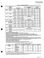
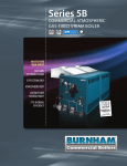
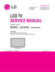
Honeywell
L404A
LM
L604A
F
D
Pressuretrol@ Controllers
IA04 and L604
PressuretrofFJ
trollers
Con
are
li7Jevoltage pressure controllers thatprovide oper
control automatic limitprotection ormanual
ating
limit protection forpressure systems
300 psi 21 1 kglcm2 or 2068 kpa
reset
of up to
I
I
i
i
I
Ii
Can be used with steam air non combustible gases
or fluids non corrosive to the pressure sensing ele
Screw
adjustments made
top of case
English psi
and Metric
ment
Scaleplates marked
kgcm2 units
Stainless steel diaphragm except 300 psi 211 kg
cm2 2068 kPa models also allows use with
monia oxygen distilled water and similar media
lA04F models available with
pean enclosure
Euro
British Standard Pipe Threads ground screw and
scaleplates marked in kglcm2 and either psi or kPa
IA04B is recommended for supervision of atomiz
ing medium pressure oil burner systems
Clear plastic cover on case to observe pressure set
tings and switch action
Models
ing
available with spst spdt or dpst switch
variety ofoperating ranges
are
and in
trouble free mercury switches all mod
els except lA04F which has snap acting switch
Dustproof
Automatic reset models have
differential except L604M
adjustable
subtractive
in
on
Leveling indicator visible through cover
Hexagonal fitting with
for direct mounting to
loop
1 4 18 NPT internal
14026 Steam Trap
Surface mount is available
holes
knockouts
in
case
using
backing
screws
eads
SIphon
through
free mechanism on manual reset models as
that limit function of controller cannot be
defeated by jamming reset lever
Trip
sures
CONTENTS
I
L Z
Rev 3 95
@Honeywelllnc
1995
Specifications
2
Ordering1nformation
2
Installation
5
Setting
and
Service
Information
Checkout
8
10
11111111111111111 I
04A D F L604A L M
JECIFICATIONS
ORDERING INFORMATION
Specitications
TRADELINE@ MODELS
TRADELINE@ models are selected and packaged to
provide ease of stocking ease of handling and maximum
replacement value Specifications of TRADELlNE@ con
trols
are
the
same as
those of standard models except
is available
exCept where noted in Table 1 The steam
trap is necessary for boiler installations
SWITCH Mercury switch es in all models except the
ES
IA04F which has a Micro Switch snap acting swit9h
PRESSURE SENSING ELEMENT Stainless steel dia
phragm brass bellows in 300 psi 21 1 kg cm2
as
noted below
2068 kPa
TRADELINE@ MODELS AVAll
ABLE
L604A Pressuretrol@ ControllersAvailable in 2 to 15 5 to
50 10 to 150 and 20 to 300 psi 14 to 1 kgcm2 14to
5 kgcm2 34 to 345 kPa
3
69 to 1034 kPa and 1
4 to 210
103 kPa
cm2
4 to
kPa
2068
ADDmONAL FEATURES
cross reference label
minus 370C also refer to
Mounting section
7 to 10 6 kg
kgcm2
Scales
are
marked in
psi and kPa
ELECfRICAL CONNECTIONS Internal screw tenninals
hole in side of case for 1
2 in conduit
MEANS
MOUNTING
Hexagonal fitting on diaphragm has
1 418 NPT internal threads for mounting on a
pipe or
steariJ trap siphon loop Also can be surface mounted
using screws through two holes knockouts in back of
with
STANDARD MODELS
MODELS IA04A D
F andL604A L
MPres uretrol@Con
trollers See Table 1 A 14026 Steam
Trap
the note in the Location and
ADJUSTMENT MEANS Screws on top ofcontroller case
138 to
TRAnELINE@ pack
models
MAXIMUM AMBIENTTEMPERA11JRE 1500F 660C
MINlMUM AMBIENT TEMPERATURE Minus 350F
siphon loop
case
Ordering Information
purchasing replacement and modernization products from
Catalog or price sheets for comple ordering number or specify
1 Order number TRADELINE4D model if desired
When
2
3
4
your
TRADELlNE@
wholesal
r or
distributor refer to the Tradeline
Operating range see Table 1
Model without steam trap if desired and available see Table I Note b
Optional specifications if desired see fable 1
Replacement parts if desired
5
6 Accessories if desired
If you have additional
1
2
questions need further infonnation or would like to conunent on our products or services please write
Your local Home and Building Control Sales Office please check the white pages of your phone directory
Home and Building Control Customer Logistics
or
phone
Honeywell Inc 1885 Douglas Drive North
4386
55422
Minneapolis Minnesota
612 951 1000
In Cmlada
Honeywell LimitedIHoneywell Limitee 740 Ellesmere Road Scarborough Ontario M1P2V9 International Sales and
Service Offices in all principal cities of the world Manufacturing in Australia Canada Finland France Germany Japan Mexico
Netherlands Spain Taiwan United Kingdom U
A
S
L404A D F L604A L M
SPECIFICATIONS
TABLE 1
ABLE
MODELS AVAll
Midscale Subtractive Differential
Action on
Pressure Rise
Operating Ranges
Setpoint
Model
to
L404A
spst breaks
2to
5 to 50
circuit
10 to
20 to
A04 8i
I
spst makes
circuit
c
15b
150b
300d
f
2 to 15d c e
5 to 50
34 to 345
138 to 2068
14 to 103
69 to 1068
14 to 103
2to6
34 to 345
circuit
10 to 150
14 to 1 0
66 to 10
2 to 15
14 to 10
2 isolated spst
circuits or 1
makes R1
W breaks R2 B
spdt
35 to 3 5
10 to 150
66 to 10
69 to 1034
4 to210
1
138 to 2068
20 to 50
14 to 10
35 to 3 5
14 to 103
34 to 345
2to6
20 to 300d
66 to 10
14 to210
69 to 1034
138 to 2068
8 to 16
15 to 40
2 to 15
14 to 10
14 to 103
spdt circuit
to
spdt circuit
103 to 276
500
35 2
3445
35
345
28 to 82
27 to 83
85
60
586
55 to 110
225
15 8
1550
103 to 276
500
35 2
3445
35
345
225
60
15 8
586
1550
500
35 2
3445
35
345
225
15 8
1550
35
345
85
14 to 41
14 to 41
41 to 97
41 to 97
85
60
586
69 to 15 2
1 4 to 35
60 to 152
138 to 345
225
15 8
35 2
1550
14 to 41
28 to 82
14 to 41
27 to 83
25
18
60
172
85
56 to 1
1
0
1 04 to 2 76
55 to 110
225
15 8
1550
103 to 276
500
35 2
3445
25
18
172
225
15 8
1550
12
manual reset g
500
3445
586
fixed subtractive differential
makes R W
breaks R B
L604M
1550
manual reset g
5 to 50i
2 to15C
5 to 50
10 to 150
15 8
fixed subtractive differential
6 to 14
10 to 22
300d
586
225
manual reset
66 to 10 6
345
60
fixed subtractive differential
1 4 to 210
35
85
14 to 103
34 to 345
69 to 1034
kPa
14 to 41
104 to 2 76
69 to 1034
138 to 2068
kglem2
14 to 41
15 to 40
2 to 15
20 to
76
2
56 to 1
10
spst makes
R W breaks R B
104 to
4 to 12
8 to 16
5 to 50
snaR makes
15 to 40
24 to 345
circuit
acting
2068
35 to
14 to 10
35 to 3
5
300d
to
psi
127 to 83
55 to 110
10
56 to 1
2to6
2 to 15
to
69
138
12
8 to 16
4to
1034
14 to 103
5
3
Maximum Surge
Pressure
14to4
14 to 41
28 to 82
14 to 1
spst breaks
switch
L604L
35 to 3 5
66 to 10 6
4 to 210
1
spdt
L604A
2to6
66 to 10 6
10 to 150
lA04F
14 to 103
b
150e
20
lA04D
14to10
20 to 300d
10 to
A04C
I
psi
to
kPa
kgfcm2
kPa
14 to 210
a
Adjustable
a
kglem2
psi
I
I
I
Switching
10 to 150
66 to 10 1
69 to 1034
fixed 3 5
psi
24 1 kPa
makesR W
breaks R B
a
Scaleplates
are
marked in both
psi and kglcm2
5A
at 120 Vac
rated for O
Model available with special fixed low differential Switch
differential in 2 to 15 psi models
C
6
midscale
subtractive
available
with
1
to
psi
L404A B and L604A models are
with
ammonia
d
for use
oxygen or other corrosive materials
Brass bellows replaces stainless steel diaphragm Not suitable
or 8 62 kPa and minimum subtractive differential of 0 5
0
09
e
of
1
25 psi
kglcm2
Model available with minimum operating pressure
b
psi
0 035 kglcm2 or 3 45 kPa
f
g
rated for 0 5A at 120 Vac
Model available with special fixed low differential Switch
to
2 controllers the trip free reset mechanism does not permit the controller
Reset
L404C D and L604L models are designated as Manual
at the
differential
is
fixed
the
reset
The
subtractive
reset device when the manual reset lever is held in
position
function
h
J
k
as an automatic
minimum value of the adjustable differential of the L404A for each
L404F only all other models have mercury switches
corresponding operating range
Model available with sealed bell crank adjustment
is installed between Rl and R2
Spst switches operate in unison spdt action when jumper
of
medium
pressure air or steam in an oil burner system
for
atomizing
Also recommended
supervision
SWITCH CONTACT RATING in amperes
at
50 60 Hz
I
I
Model
Load
L404A
Full Load
Locked Rotor
Norimductiv
L604A
Lb
Full Load
Locked Rotor
Noninductive
L604M
a
b
Full Load
120 Vae
240 Vac
120 Vde
4
24 0
240 Vde
12
12 0
20
80
48 0
10 0
1
5
30 6
50
80
48 0
10 0
51
30 6
50
20 0
80
10
10 0
40
10
5
0
10
5
0
5 0
20
L404F snap acting does not have non inductive or dc ratings
L6 4A and Lhave also beentested andlisted by Underwriters Laboratories Inc and breaking not making
at 120 Vac
ratmg of 9 8 A full load plus 360 VA ignition plus 250 VA pilot duty
1
a load
with
atotal
flO 21 50
1 0
404A D F L604A L M
JPECIFICA nONS
DIMENSIONS See Fig 1 See Fig 2 for
mounting s
trap siphon loop
WEIGHT 2 me 0 91 kg
FINISH Gray
APPROVALS
Underwriters Laboratories Inc listed IA04A B C D F
L M only file no MP466
L604A
l0
v01
no
REPLACEMENT PARTS
129178 Thermoplastic Cover
14026 Steam Trap
siphon loop l4 in
Necessary for boiler installations
ACCESSORlES
33312B Knurled
on
Canadian Standards Association certified
L604A L
only
B C
LA04A
DF
guide noAOO E O
file no LR1620
TABLE 2
I
main scale pressure
Screw and 23466 Wrench
ONVERSION TABLE psi
Operating Range
psi
o
to
2 to 15
5 to 50
Equivalent
Scale Plate
kglcm2
kPa
OtolO
o to 103
14 to10
3 to 3 5
15
to kPa
Subtractive DitTerential
Equivalent
Scale Plate
psi
kglcm2
kPa
14 to 103
1 to 6
2to 6
07to4
14 to 4
7 to 41
14 to 41
34 to 345
4to 12
5 to 14
3 to 8
4 to 10
28 to 83
41 to 97
5 to 150
3 to
3
10
34 to 1034
10 to 150
7 to 10 3
69 to 1034
8 to 16
10 to 22
6 to 1
7 to 15
20 to 300
55 to 110
69 to 152
14 to 20 7
138
15 to 40
20 to 50
10 to 2 8
14 to 3 5
103 to 276
138 to 345
Flg
Mountlng dimensions
1
LA04A
of the
to
2068
L404A B C D F and L604A L M pressuretroP Controllers in in
Fj L
604A
I
M
41
l
3 COVER
114
4
1
16
1S
32
11
at4
2
3 CASE
110
2
49
16
G
3
Hl1164
0
81
32
1
29A
49
9
69
6
j
1
I
3 7
6
23
3
32
4
lI8
1r
5
94
31 32
4
2
126
1 1M6
48 0
J
Me 4 6X 21164
L
3
6
KNOCKOl1T 2
1
RESET LEVER ON MANUAL RESET MOOas
ONLY
iHISOIMENSION
AND 534 N
ONLYON
hO
1
1
IS
AMM
l48
27132IN t23
eo4MOOas
ON t
0MM
Ui04MOOasWITHA2TO
ON lJi04MOOasWITHA21O
WlTHA2010 300 PSI
15 PSI
1410 1 0
kgIan2
1f38 1
OPERATINGRANae
1SPSl 14 TO 1 0kg
an 1410103 kPa
1 4 TO 2A7 iqycm2 13810
a OPERATING RANGE
2068Jd
14 10 103
pipe
Adjustment Knobwith setscrew fits
adjusting screw
4074BWJLimitStop
tolimit set point ranges
Assembly
ineludes 129564 Range Stop 107194 Range
Stop
guide
MBPR
black iron
kPo
OPEAAllNG RANGE
n
mm
F l604A lM
D
l404A
INSTALLATION
Installation
WHEN INSTALLING TIllS PRODUCT
1 Read these instructions carefully Failure to follow
hazardous
them could damage the product or cause a
Rlght and
loop
siphon
trap
Fig
2
sions in in
a steam
wrong mounting of
dimen
with approximate
mm
condition
and on the
2 Check the ratings given in the instructions
the product is suitable for your
ct
to
make
sure
prod
application
3 Installer must be a tramed
guard control
expenenced
flame safe
technician
4 After installation is complete check out
as provided in these instructions
product
operation
ffi CAUTION
supply before beginning in
prevent possible equipment dam
1 Disconnect power
stallation to
age or electrical shock
2
using the controller with a compressor
installa dampening device suchas aneed1e valve
header or surge tank to dampen pulsations that
When
can
damage the controlleror reduce its life
IN BLACK IRON PIPE WITH 1 4 18 NPT EXTERNAL
TRHEADSON BOTH ENDS
lD THE STEAM TRAP
BEf
SIPHON LOOP TO LEVEL THE CONTROLLER
1 4
IMPORTANT
Locate the controller where the ambient temperature
will not exceed 1500F 660C
2 Use pipe compound sparingly to avoid clogging the
hole in the pipe or diaphragm fitting
thecontroller by hand by holding the case
3 Do not
M8934
1
tighten
4 Accurately level the controllerfor proper operation
Make all
pipe connections in accordance
standards Use
To avoidleaks anddamage to the case
NOTE For most accurate operation add supplemental heat
to installations where the temperature falls below minus
Never locate the controller where the
200P
minus 290C
falls below minus 350P minus 370C be
mercury in the switch freezes at this temperature
temperatUre
When used with steam boilers always mount the con
troller above the water line in the boiler A steam trap
loop must always be connected between the con
Fig 2 to prevent boiler scale and
corrosive vapors from attacking the diaphragm The loop
to the face
on the steam trap must always be perpendicular
to
controller
If
the
of the controller
the loop is parallel
the
controller
and
or
contraction
ofthe
expansion
loop tips
causes the switch to operate inaccurately
The controller can be mounted 1 alongside the pres
2 in a fitting on the boiler provided by e
sure gauge
the boiler
manufacturer
vibration
or
3 at
4 in
a remote
a
location in
special mounting
with approved
compound
to
seal the connection joints Excess pipe compound can clog
the small hole in the fitting and prevent the controller from
case
controller
use a
wrench
hexagonal fitting
the controller by hand by holding the case
on the
siphon
troller and
amount of pipe
operating properly
LOCATION AND MOUNTING
cause
only
a small
s
parallelJaw
Do not tig
ten
LeveUng
A controller with a mercury switch must be
accurately
leveled for proper operation It is level when the leveling
indicator Fig 11 hangs freely with its pointer directly
over the index mark inside the back of the case Level the
controller
bycarefu11y bending
the steam trap
siphon
loop
Mounting Alongside a Pressure Gauge
To mount the controller alongside a pressure gauge
Fig 2 remove the gauge In its place install a steam ap
siphon loop with a tee on top Using elbows and pIpe
nipples moUnt the controller and pressure gau e on the
ends ofthe tee Level the controller after installattOn
of excesSIve
on a
low water
cutoff
I
11
L404A D F
L M
L604A
INSTALLATION
Mounting on a Boiler
If it is
convenient to mount the controller
the pressure gauge install a steam trap siphon
not
alongside
loop in the
Fig
3L404 terminal blocks and internal
schematics
fitting provided by the boiler manufactUrer If there is no
fitting mount the steam trap at a location recommended by
RISE
RISE
the boiler manufacturer Screw the controller
directly to the
steam trap and level the controller
Mounting at a Remote
B
Location
If there is excessive vibration at the boiler that
can
adversely affect the operation of the controller mount the
controller at a remote location All
piping from the boiler
must be suitable and
solidly
mounted The
piping must
be
properly pitched
condensation back to the
boiler A steam trap
siphon loop must be mounted be
to drain all
tween
the remote
piping
and the controller Level the
L404AC
L404B D
L404F
SNAP ACTING
BREAKS ON
PRESSURE RISE
TO SETPOINT
MAKE ON
PRESSURE RISE
BREAKS R
a
MAKES R WON
TO SETPOINT
PRESSURE RISE
TO SETPOINT
controller after installation
M8941
Supervision of Atomizing Medium Pressure
Air or
Steam
L404B
When air or steam is used
oil burner system
bodies and codes
4L404 terminal block and Internal
Fig
atomizing medium in an
authorities having jurisdiction approval
as an
schematic
often require a low limit to
prevent
main oil valve until sufficient
atomizing pres
is present and to shut down the
when the
opening the
sure
system
pressure falls too low
The L404B is recommended for this
application It
makes a circuit when the pressure rises to the set
and
atomizing
point
breaks when the pressure falls to the set
differential Fig 10
point minus
the
WlRING
t
1
the power supply before
DiscoDDe
beginning wiring
preventelectrical shock or equipment damage
2 Assume all wiring complies with applicable electrical
co
ordinances and regulations Use NEC Class 1
line
voltage wiring
L604A
to
3 Fornormalinstallations
wire sUitable for at least
use moisture
1 750C
1670
least 1940F
control
a flame
maximum
use
a7
cable
ing tIie screw
or
vided
cover
Fig
8 in
or
22 2 mm hole in one side for 12 in
wires Remove the front cover
loosen
by
Fig 5 through 9 for
boiler manufacturer
typical hookups Follow
wiring diagram if pro
s
7
Make sure the loads do not exceed the Switch Contact
Ratings in the Specifications section
8
Replace
SPDT SWITCH ACTION WITH JUMPER INSTALLED
M8935
OTHERWISE TWO ISOLATED SPST SWITCHES
SL404 used
controller
Fig
as a
limit
or as an
operating
SPST
CONTROLLER
Ll
HOT
POWER
SUPPLY
1
Lll
FlAME
SAFEGUARD
CONTROL
MOTOR OR
OTHER LOAD
U
at the bottom of the main scale
6 Refer to
the burner
the
operating temperature
3 and 4 and
BREAKS R2 8
ON PRESSURE RISE TO SETPOINT
moisture resis
temperature rating above
5 All models have a terminal block inside the
condui
are
control
4 For high temperature installations
tant No 14 wire selected for a
L604L M
W
resistant No 14
when you
using
or at
safeguard primary
900C when using it with a programming
the controller with
MAKES Rl
the front cover when
wiring is completed
PROVIDE DISCONNECT MEANS AND OVERLOAD PROTECTION
AS REQUIRED
HIGH UMITl404A OR CBREAKS WHEN PRESSURE RISES
TO SETPOINT
4048 BREAKS WHEN PRESSURE FALLS TO SETPOINT
LOW
t
UMIT
MINUS DIFFERENTIAL
404A BREAKS WHEN PRESSURE RISES
OPERATING
t
CONTROLLER
TO SETPOINT AND MAKES AGAIN WHEN PRESSURE FALLS TO
SETPOINT MINUS DIFFERENTIAL
M8936
L404A D F L604A L M
INSTALLATION
Fig
6 l404 with a low
Fig
voltage relay
8l404F l604A with
l604M used as
a
jumper
low limit with
installed
an
or
alarm
circuit
SPOT
LOW VOLTAGE RELAY
CONTROUER
L1
HIGH
HOT
POWER
SUPPLY
24 VOLT
THERMOSTAT
UMIT
1
a
L2
Ll
FlAME
HOT
SAFEGUARD
CONTROl
POWER
SUPPLY
Lb
MOTOR OR
OTHER
12
LOAD
LOAD
ALARM
PROVIDE DISCONNECT MEANS AND OVERLOAD PROTECTION
AS REQUIRED
M8940
PROVIDE DISCONNECT
AS REQUIRED
MEANB AND
BRE R TO B AND MAKES
AKS
TO SETPOINT
OVERLOAD PROTECTION
R TO W WHEN
PRESSURE
RISES
M8938
Fig
as a
l404F l604A Oump r installed
high limit with an alarm circuit
7
used
Fig 9L404F
controlling an
SPOT
or L604 wlth
jumper installed
M644B motor
CONTROUER
LOW UMfT
SPOT
CONTROLLER
W
UNEVOLTAGE
lWO POsmON MOTOR
WHITE
CLOSED
LOW ARE
Ll
HOT
FlAME
SAFEGUARD
POWER
SUP PLY
CONTROL
MOTOR OR
OPEN
HIGH
FIRE
OTHER LOAD
12
Ll
HOT
POWER
SUPPLY ill
L2
PROVIDe DISCONNEct
BLACK
BLACK
MEANS AND OVERLOAD PROTECTION
MB44B
AS REQUIRED
BREAKS R TO WAND MAKES R TO B WHEN PRESSURE
FALLS TO SETPOINT MINUS DIFFERENTIAL
MB937
PROVIDE DISCONNECT
AS REQUIRED
MeANS
AND OVERLOAD PROTECTION
BREAKS R TO B AND MAKES R TO
RISES TO SETPOINT
W WHEN
PRESSURE
M8939
F L604A L M
D
ETTING AND CHECKOUT
04A
Setting and Checkout
automatic
illy
will not
main scale setpoint They
controllers
one
these
reset
of
their fonner positions To
to
the
set
point minus the
wait until the pressure falls
reset lever
the
manual
differential Fig 10 Then depress
not
be
reset until
will
it The controller
Fig 11 andrelease
reset
This
lever
prevents the con
the manual
you release
reset
device if the reset
troller from becoming an automatic
or
down
tied
lever is stuck held in
return to
SETIING
is subtractive from the
In all models the differential
The
upper operating point is deter
main scale set point
set
scale
main
point while the lower operat
mined by the
the main scale setting less the
ing point is determined by
and L604A with jumper
The
L404F
differential setting
installed L M have spdt switching action
are
Operating points
shown in Fig 10
1oL404 and L604
Fig
Fig
operating points
11
Setting
a
JrPreetrossl i
Controller
MAIN SCALE SETPOINT
SWITCH BREAKS
SUBTRACTIVE
DIFFERENTIAL
L404A C
PRESSURE
RISE
I
DIFFERENTIAL SETTING
SWITCH MAKES
MAIN
SCALE
SETPOINT
SWITCH MAKES
SUBTRACTIVE
DIFFERENTIAL
L404B D
PRESSURE
RISE
I
4
DIFFERENTIAL SETTING ill
SWITCH BREAKS
4
MAIN SCALE SETPOINT
B MAKES R W ill
BREAKS R
L404F
L604
M PRESSURE
RISE
I
SUBTRACTIVE
DIFFERENTIAL
DIFFERENTIAL SETTING
MAKES R
B BREAKS R
W
a
MAIN SCALE SETPOINT
8
R2
Rl W BREAKS
MAKE
SUBTRACTIVE
DIFFERENTIAL
L604A
PRESSURE
RISE
DIAPHRAGM
ASSEMBLY
DIFFERENTIAL SETTING
BREAKS Rl W MAKES
8
R2
RESET
S HAVE A SMALL AXED
MeDB
lA04C D AND l604L MANUAL
PRESSURE
DIFFERENTIAL THEY CAN BE MANUALLY RESET WHEN THE
MINUSTHE
DIFFERENTlAL
SETPOINT
FALLS TO THE MAIN SCALE
604M HAS
l
A
AXED DIFFEAENTlAL
SMALl
OF 3 5 PSI 0 25
INDICATOR
B F L404L WITH A5 TO
ADJUSTABLE DIFFERENTIAL ON THE L404A OPERATING RANGE
34 TO 134 kPal
150 PSI 0 34 TO 103 kglcm2
ONLY
AND L604A MODELS
RESET LEVER ON THE L404C D AND L604L
TRIP FREe MANUAL
MODELS ONLY
kgIcm2
MIlIl43
W
for the desired
operating
Adjust the main scale set point
screw Fig 11
the
main
scale
adjusting
pressure by turning
case until the main scale setting indicator
on the top ofthe
L404A B F with a 5 to 150 psi
is at the desired value On an
2
1034
kPa
34
to
operating range or an
3 kg cm
10
3 to
differential
the
setting
by turning the dif
L604A adjust
screw Fig
11 until the differential
ferential adjusting
setting
indicator is at the desired value L404C D and
models see the next paragraph
are manual reset
L604L
differential The scaleplates
The L604M has a fixed
cm2
marked psi arid kg
are
Free Manual Reset Feature
D and L604LonlyL404D makes and the L604L
L404C
The L404C breaks the
B when the pressure rises to the
makes R W and breaks R
Trip
CHECKOUT
wired and set test it
After the controller has is installed
allow
the system to
First
with the system in operation
while
ofthe
controller
the
operation
stabilize Then observe
should increase
Pressure
its
setpoint
raising and lowering
raised and decrease when the set point
when the setpoint is
is lowered
break points of the controller
Also check the make and
a
accurately calibrated
If they do not agree with separate
s may
a slight adjusnnent ofthe scaleplate
pressure gauge
be necessary
when checking
Use accurate pressure testing equipment
not rely on inexpensive gauges The
out the controller Do
calibrated at the factory
controllers are carefully
L404A
F L604A L M
D
SETTING AND CHECKOUT
Boiler Installation
If the controller is being used on a boiler installation
it as follows
test
ffi CAUTION
Do not
1 Note the boiler pressure
sure gauge
To perform this
by checking the boiler pres
testproperly the boiler should
have
or
control and any others
burner and boiler manufacturers
safeguard
required by tlie
corresponds
gauge readiri g
3 TheL404A or C should break the control circuit s
automatically when the boiler pressure gauge reading equals
or slightly exceeds the controller
setting
b9iler pressure
The L404B
service until you have
all
applicable tests de
scribed in this Checkout section in the Checkout
section of the applicable instructions for the flame
a pressure reading near the middle
of the controller s
main scale range
2 Turn the main scale
adjusting screw Fig 11 until the
rlnscale
m
to
setting indicator on the controller
th
put the system into
satisfactorily completed
D should make the circliit under the
Fig
12
Checking
controller
operation using
an ohmmeter
same
circumstances
The L404F
M should
L604L
break the R B circuit under the
MAIN SCALE
inake the R
same
ADJUSTlNG
W circuit and
circumstances
SCREW
The L604A should make the RI W circuit and break the
R2 B circuit under the
same
circumstances
4 If the controller is operating
properly turn the main
scale adjusting screw Fig 11 until the main scale
setting
indicator is at the desired set
Ifa Controller Seems to
Ifthe controller is
point
Operate Improperly
of operating
iniproperly
suspected
it
may be further checked as follows Fig 12
1 Disconnect all power to the controller loosen the
cover screw and remove the cover
MAIN
SCALE
SETllNG
INDICATOR
2 DisconneCt the wires from the controller
3 Connect an ohmmeter between the switch terminals
4 Lower the set point of the controller
a
simulating
pressure increase through a range greater than the differen
tial The switch should either make or
break depending on
the model ofthe controller AnL404A orC should
an
break
L404B
orD
should make
IA04F
M should break
L604L
R B and make R W and an L604A should breakR2 B and
make RI W If it makes the ohmmeter reads
zero if it
breaks the ohmmeter reads infinity
I
an
5 Raise the set point of the controller
simulating a
pressure decrease through a range greater than the differen
tial The switch should break or make
just the opposite ofits
action in step 4 except for the L404C D and L604L manual
reset models
I
00
INPUT
I
SETPOINT
I
OUTPUT
I
DEqREASE
I
I
I
I
I
I
I
I
I
o
I
I
280
I
I
I
ADJ
ro
NOTE An
approximation ofthe differential can be made by
observing the change in set point required for aresistance
change from zero to infinity
6 Ifthe controller operates
7 When the controller is
the wires to
the cover
improperly replace
it
operating properly reconnect
the terminal block
replace the cover and tighten
screw
and reconnect the power
ZERO OHMS
INANITY WHEN R B BREAKS
AN l604 WITH JUMPER INSTALLED
BElWEEN Rl AND R IS SHOWN
AN L404F OPERATES SIMIlJ RL Y SPOT
SWITCHING AN L404A B C
OR 0 HAS ONLY TWO TERMINALS
SPST SWITCHING AN L404A
OR C BREAKS AND L404B OR 0 MAKES WHEN THE SETPOINT
IS
DECREASED FAfl ENOUGH
M8944
Q4A D F L604A L M
RVICE INFORMATION
Service Information
MAINTENANCE
CALmRATION
The controller
carefully calibrated during manufac
not
require recalibration Most calibra
turing and should
caused
by improper leveling The controller
tion errors are
the
when
should be level
pointer onthe leveling indicator is
The
was
directly
over
the index mark
leveling indicator may not be
Fig
11
accurate
In
some cases
enough
the
The pointer
the index mark but the controller still may not
may be over
tolerance of its scale setting In this
be operating within the
bend the steam trap siphon loop until the
case
carefully
controller switches properly
to
at all times
ofthe controller should be in place
from
dirt
dust and
the internal components
cover
protect
should consist of
away any
maintenance
physical damage Routine
or brushing
and
blowing
occasional inspection
functioning of
accumulated dirt and dust To ensure proper
check of
times perform an operational
the controller at all
the entire system
during routine
maintenance checks