1
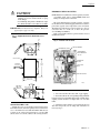
L8151A
Triple Aquastat® Relay
The L8151A is a remote bulb controller for use
with hydronic heating systems that include domestic hot water service.
■ Provides high limit, low limit, and circulator control
for maintaining boiler temperatures.
■ Can provide multizone control by using a separate
thermostat and R845 Relay for each zone.
■ Shielded capillary allows convenient mounting.
■ Consists of a diaphragm powerhead and micro switch
assembly that responds to temperature changes in
the boiler water.
■ An internal transformer powers the thermostat circuit.
CONTENTS
Specifications ................................................. 2
Ordering Information ..................................... 2
Installation ..................................................... 2
Operation and Settings ................................... 5
Checkout ......................................................... 6
J. H. • Rev. 11-95 • ©Honeywell Inc. 1995 • Form Number 60-2553—3
60-2553—3
L8151A
SPECIFICATIONS • INSTALLATION • ORDERING INFORMATION
Specification
IMPORTANT: The specifications given in this publication
do not include normal manufacturing tolerances.
Therefore, this unit may not exactly match the listed
specifications. Also, this product is tested and calibrated under closely controlled conditions, and some
minor differences in performance can be expected if
those conditions are changed.
MAXIMUM AMBIENT TEMPERATURE: 150°F (66°C)
at case. 265°F (130°C) at sensing element.
PRESSURE RATING: 200 psi (1380 kPa) on outside of
immersion well.
THERMOSTAT HEAT ANTICIPATOR SETTING: 0.2A.
LOW LIMIT (Fig. 2):
Function: Maintains water temperature at setting during
thermostat off periods.
Setting: 110°F to 220°F adjustable (43°C to 104°C).
Differential: 10°F to 25°F adjustable (6°C to 14°C).
HIGH LIMIT (Fig. 2):
Function: Opens burner circuit if water temperature reaches
high limit setting.
Setting: 130°F to 240°F adjustable (54°C to 116°C).
Differential: 10°F fixed (6°C).
MOUNTING MEANS: Mounting lugs on back of case.
DIMENSIONS: See Fig. 1.
SENSING ELEMENT: 3/8 x 2-7/8 in. (10 x 73 mm).
CAPILLARY LENGTH: 36 in. (914 mm), armored
capillary.
UNDERWRITERS LABORATORIES INC. LISTED: File
No. MP466, Guide No. MBPR2.
MODEL: L8151A Triple Aquastat® Relay for remote bulb
control of hydronic heating systems that include domestic
hot water.
ELECTRICAL RATINGS:
Power Supply: 120 Vac, 60 Hz; 220 Vac, 50 Hz and
240 Vac, 60 Hz operation.
Contact Ratings (A): See Table 1.
TABLE 1—CONTACT RATINGS.
Full Load
Locked Rotor
120 Vac
7.4
44.4
240 Vac
3.7
22.2
MAXIMUM POWER CONSUMPTION: 8W at 120 Vac,
60 Hz.
Installation
WHEN INSTALLING THIS PRODUCT...
1. Read these instructions carefully. Failure to follow
them could damage the product or cause a hazardous
condition.
2. Check the ratings given in the instructions and on
the product to make sure the product is suitable for your
application.
3. Installer must be a trained, experienced service
technician.
4. After installation is complete, check out product
operation as provided in these instructions.
WARNING
CAN CAUSE PROPERTY DAMAGE,
SEVERE INJURY OR DEATH.
Product is for use only in a system with a pressure
relief valve.
Ordering Information
When purchasing replacement and modernization products from your TRADELINE® wholesaler or distributor, refer to the Tradeline®
Catalog or price sheets for complete ordering number, or specify—
1. Order number.
3. Order additional system components and system
2. Accessories, if desired.
accessories separately.
If you have additional questions, need further information, or would like to comment on our products or services, please write or phone:
1. Your local Home and Building Control Sales Office (please check the white pages of your phone directory).
2. Home and Building Control Customer Logistics
Honeywell Inc., 1885 Douglas Drive North
Minneapolis, Minnesota 55422-4386
In Canada—Honeywell Limited/Honeywell Limitée, 35 Dynamic Drive, Scarborough, Ontario M1V 4Z9. International Sales and
Service Offices in all principal cities of the world. Manufacturing in Australia, Canada, Finland, France, Germany, Japan, Mexico,
Netherlands, Spain, Taiwan, United Kingdom, U.S.A.
60-2553—3
2
L8151A
INSTALLATION
IMMERSION WELL MOUNTING
CAUTION
NOTE: Immersion well must be ordered separately. For a list
of available wells, refer to form 68-0040, Wells and
Fittings for Temperature Controllers.
• Disconnect power supply before beginning installation to prevent electrical shock or equipment damage.
• Avoid making sharp bends or kinks in the capillary. Bends should be no less than 1 in. (25 mm).
The boiler manufacturer generally provides a tapping
for the immersion well. This tapping should be located at a
point where typical water temperature can be measured.
The immersion well must never be located close to a hot or
cold water inlet or a steam coil, or where the pressure
exceeds 200 psi (1380 kPa).
If the system is filled, drain to a point below the selected
installation location.
IMPORTANT: Terminals on these Aquastat® Relays are
approved for copper wire only.
Fig. 1—Approximate L8151 dimensions in in.
(mm).
1/8
(3)
Fig 2— Internal view of L8151.
2-3/16
(56)
VOLTAGE BARRIER
GROUNDING SCREW
1-1/2
(38)
TRANSFORMER
FOR THERMOSTAT
CIRCUIT
1-7/16
(37)
13/64 X 21/64 (4)
DIFFERENTIAL
SETTING
CAPILLARY
30 IN. (762)
6-1/8
(156)
CIRCULATOR
RELAY
4-1/2
(114)
LOW LIMIT SETTING
4-5/16 (110)
4-23/32 (120)
KNOCKOUT
FOR 1/2 IN.
CONDUIT (5)
HIGH LIMIT SETTING
1-1/4
(32)
1-1/4
(32)
M8893
13/16
(21)
2-3/6
(56)
1. Screw the well into the boiler, tank, or pipe tapping.
3-5/16
(84)
2. Insert the bulb into the well, pushing tubing until bulb
bottoms in well. Avoid making sharp bends or kinks in the
capillary. Bends should be no sharper than 1 in. (25 mm)
radius.
M8892
3. Attach the retainer clamp to end of well spud. Loosen
draw nut and spread jaws of clamp with screwdriver if
necessary, Fig. 3.
MOUNTING THE CASE
Mount the case in a convenient location near the boiler.
Remember that the shielded capillary must reach from the
case to the immersion well. This maximum ambient temperature of the selected location must not exceed 150°F
(66°C) at the case, 265°F (130°C) at the sensing element.
3
60-2553—3
L8151A
INSTALLATION
All wiring must comply with local electrical codes and
ordinances. The limits given in the Specifications section
must not be exceeded when applying this control. Use
manufacturer instructions when wiring controlled equipment or refer to typical hookups in Fig. 4 through 6.
When the B1 terminal on the device being replaced is
1/4 in. tab terminal, use the existing wiring harness terminals to install the replacement device. When the B1 terminal on the device being replaced is a screw terminal, insert
the provided tab terminal to screw terminal adapter on the
1/4 in. tab terminal of the replacment device. After the
adapter is installed, the existing wraparound wire end can
be reused to make an electrical connection to the B1 terminal.
Fig. 3—Remote bulb installation.
JAWS
SPREAD JAWS
TO FIT OVER
RIDGE ON SPUD
OF WELL
SCREWDRIVER
INSERT— MOUNTING CLAMP
DRAW
NUT
MOUNTING
CLAMP
B
SPUD
NOTE: Do not use a push type ratchet screwdriver.
WELL
BULB
TUBING
1. Strip 7/16 in. of insulation from the wire end.
2. Wrap the wire at least three-fourths of the distance
around the screw as shown.
3. Using a standard, flat-headed screwdriver, tighten the
screw until the wire is snugly in contact with the screw and
contact plate.
4. Tighten the screw an additional one-half turn.
M8777
A
4. With part no.121371AA Retainer Clamp attached to
well spud (be sure jaws of clamp hook over ridge at end of
spud, as shown at points A), adjust tubing to fit through
retainer clamp groove, as shown at point B.
5. Tighten draw nut so that retainer clamp is firmly
attached to well spud and tubing is held securely in place. Be
careful not to damage the capillary.
6. Carefully coil the excess capillary at the bottom of the
Aquastat® case.
Fig. 4—Typical hookup for L8151A in a single
zone system.
LOW VOLTAGE
THERMOSTAT
T
THERM.
T
ZC
WIRING
CAUTION
ZR
• Disconnect power supply before wiring to avoid
electrical shock or equipment damage.
• Be sure the terminal connections are inside an
enclosure that meets local codes.
B1
X
2
X
1
3
X
OIL BURNER
RELAY
LINE TERMINAL
OR
BURNER
X
X
B2
LINE VOLTAGE
GAS VALVE
X
C1
IMPORTANT: Terminals on the L8151A Aquastat® Relay
CIRC.
L1
(HOT)
1
LINE
2
G
NOTE: Do not use a push-type ratchet screwdriver.
60-2553—3
LINE VOLTAGE
CIRCULATOR
C2
are approved for use only with copper wire. The
terminals allow wraparound wiring only.
1. Strip 7/16 in. of insulation
from the wire end.
2. Wrap the wire at least three
fourths of the distance around
the screws as shown.
3. Use a standard flat-headed
M8843
screwdriver to tighten the
screw until the wire is snugly
in contact with the screw and contact plate.
4. Tighten the screw an additional one-half turn.
4
1
L2
2
1
POWER SUPPLY. PROVIDE DISCONNECT MEANS AND
OVERLOAD PROTECTION AS REQUIRED.
2
CONTROL CASE MUST BE CONNECTED TO EARTH GROUND.
USE GROUNDING SCREW PROVIDED.
3
B1 IS 1/4 IN. TAB TERMINAL.
M8886
L8151A
OPERATION AND SETTINGS
Operation and Settings
HIGH LIMIT
The high limit opens and turns off the burner when the
water temperature reaches the setpoint. The high limit
automatically resets after the water temperature drops past
the setpoint and through the 10°F (6°C) differential.
Fig. 6—L8151A internal schematic.
2
1
WARNING
T
CAN CAUSE PROPERTY DAMAGE,
SEVERE INJURY OR DEATH.
Product is for use only in a system with a pressure
relief valve.
1K
T
HIGH LIMIT
B2
1K2
B1
R
ZR
LOW LIMIT AND CIRCULATOR CONTROL
On a temperature rise, with the adjustable differential at
the minimum setting of 10°F (6°C), the low limit circuit
(RB) breaks and the circulator circuit (R-W) makes at the
control setpoint. On a temperature drop of 10°F (6°C)
below the setpoint, the R-B circuit makes and the R-W
circuit breaks.
B
ZC
1K1
C2
W
C1
TO ADDITIONAL
R845A RELAYS
FOR OTHER ZONES
10°F (6°C)
DIFFERENTIAL
2
THERMOSTAT
ZONE 2
1
SWITCH BREAKS ON
TEMPERATURE RISE.
BURNER TURNS OFF.
CIRCULATOR OPERATES
ON A CALL FOR HEAT.
HIGH LIMIT
SETTING
R845A RELAY
ZR
SWITCH MAKES ON
TEMPERATURE FALL.
BURNER OPERATES ON A
CALL FOR HEAT.
4
4
3
B1
LOW LIMIT
AND
CIRCULATOR
SETTING
3
5
B2
6
CIRCULATOR
ZONE 1
CIRCULATOR
ZONE 2
C2
L1
(HOT)
1
1
LINE
110°F (43°C)
L2
2
1
G
25°F (14°C)
DIFFERENTIAL
10°F (6°C)
DIFFERENTIAL
C1
CIRC.
M8884
240°F (116°C)
ZC
BURNER
CIRCULATOR
CONTROL
Fig. 7—Relationship of setpoints and differential.
Fig. 5—Typical hookup for the L8151A in a
multizone system.
T
THERMOSTAT
THERM. ZONE 1
T
LOW
LIMIT
2
HYDRONIC HEATING
CONTROL TERMINALS
IF CONTROLLING TWO LOADS USE:
—TERMINALS 3 AND 4 FOR LINE
VOLTAGE LOAD.
—TERMINALS 5 AND 6 FOR LINE
OR LOW VOLTAGE LOAD.
1
POWER SUPPLY. PROVIDE DISCONNECT MEANS AND
OVERLOAD PROTECTION AS REQUIRED.
2
CONTROL CASE MUST BE CONNECTED TO EARTH GROUND.
USE GROUNDING SCREW PROVIDED.
3
LINE VOLTAGE OIL BURNER CONTROL OR GAS VALVE.
4
B1 IS 1/4 IN. TAB TERMINAL.
SWITCH MAKES R-W
AND BREAKS R-B ON
TEMPERATURE RISE.
1
SWITCH MAKES R-W
AND BREAKS R-B ON
TEMPERATURE RISE.
SWITCH MAKES R-B AND
BREAKS R-W ON
TEMPERATURE FALL.
BURNER IS ON TO
MAINTAIN MINIMUM
WATER TEMPERATURE.
CIRCULATOR IS OFF.
WHEN WATER REACHES PROPER TEMPERATURE, THE BURNER
SHUTS OFF OR THE CIRCULATOR PUMP STARTS (WHEN CALLING
FOR HEAT).
M1523
At any differential setting greater than 10°F (6°C), the
R-B make and R-W break temperatures remain the same
(control setting minus 10°F (6°C). The R-B break and R-W
make temperatures are the setpoint temperatures plus the
difference between the differential setting and 10°F (6°C).
M8885
5
60-2553—3
L8151A
OPERATION AND SETTINGS • CHECKOUT
EXAMPLE: Setpoint of 140°F (60°C) differential set at
25°F (14°C). On a temperature rise, R-B breaks and
R-W makes at 155°F (68°C). On a temperature fall,
R-B makes and R-W breaks at 130°F (54°C); see
Fig. 7.
THERMOSTAT ANTICIPATOR
Set the thermostat heat anticipator at 0.2A.
Checkout
Put the system into operation and observe each function through at least one complete cycle. Be sure the control operates
as intended.
Automation and Control Solutions
Honeywell International Inc.
1985 Douglas Drive North
Golden Valley, MN 55422
60-2553—3
Honeywell Limited-Honeywell Limitée
35 Dynamic Drive
Scarborough, Ontario M1V 4Z9
6


![取扱説明書〈詳細版〉 [F-04B]](http://vs1.manualzilla.com/store/data/006532339_2-7161c531ccad3db4d0b2b0530d68e7ed-150x150.png)


![MS-1190-1260_E_0204 [更新済み]](http://vs1.manualzilla.com/store/data/006615042_2-60a6c199ae6e29d21d1311965ba9696a-150x150.png)