1
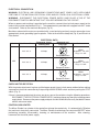
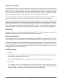
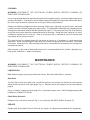
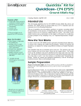
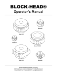
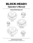
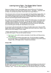
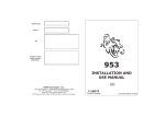
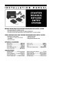
I
N
S
TR
U
C
TI
O
N
S
MODEL 4352 MIXER-GRINDER
MODEL
4352
ML-104650
ML-104651
ML-104654
ML-104655
R.H. Standard Hopper (Without Side Feed Opening)
L.H. Standard Hopper (Without Side Feed Opening)
R.H. Optional Hopper (With Side Feed Opening)
L.H. Optional Hopper (With Side Feed Opening)
WORLD HEADQUARTERS
701 RIDGE AVENUE
TROY, OHIO 45374-0001
FORM 33737 (10-96)
Installation, Operation, and Care of
MODEL 4352 MIXER-GRINDER
SAVE THESE INSTRUCTIONS
GENERAL
The Model 4352 Mixer-Grinder is equipped with a 10 HP motor which rotates the mixing arm at 29 RPM and
the worm at 222 RPM. The 4352 is designed to use a #52 size knife and plate (knives and plates are
available at extra cost but not included with grinder). Do not use a plate with hole size smaller than 3/32".
The hopper can hold up to 275 pounds for first grind, depending on type of product; up to 300 pounds
for second grind. The machine can grind at a rate of 80 to 100 pounds of fresh boneless beef per
minute, first or second cut through a 1/8" plate. Frozen meat must be tempered to 24°F or higher before
grinding and can be in flake or stick form. Pork can be ground first cut through a 3/4" breaker plate at
up to 80 pounds per minute; and second cut through a 3/16" plate at 40 to 80 pounds per minute.
Optional equipment, available at extra cost, includes the following:
1) Flexible power supply cord and plug. Either a receptacle or a pendant type connector is available.
The receptacle requires a type FD electrical box (not supplied).
2) Legs with casters (4 lengths are available). NOTE: Machines with casters are equipped with
flexible power supply cord and plug. Either a receptacle or a pendant type connector is available.
The receptacle requires a type FD electrical box (not supplied).
3) Legs without casters (4 lengths are available).
4) Pneumatic foot switch (accessory).
5) A side feed inlet can be ordered (and factory installed) for either the right- or left-hand side of the
hopper to allow product from a companion first cut grinder to feed directly into the hopper. A plug
assembly is available for use when the side inlet hole is not in use.
6) #52 size knives and plates.
NOTE: With the proper adapter ring, the mixer-grinder can be connected to other grinders having either
a #32 (42/ 46), #52, or #56 chopper end, assuming the height of the side feed inlet can be met.
INSTALLATION
Immediately after unpacking the mixer-grinder, check for possible shipping damage. If the machine
is found to be damaged, save the packaging material and contact the carrier within 15 days of delivery.
Prior to installation, test the electrical service to make sure it agrees with the specifications on the
machine data plate (Fig. 3).
PNEUMATIC FOOT SWITCH
Remove the cap from the barbed fitting adjacent to the electrical supply junction compartment (Fig. 1)
and connect the tube from the pneumatic foot switch onto the barbed fitting using the clamp provided.
A pliers will be needed to squeeze the clamp open during installation. Avoid kinking the tube.
© HOBART CORPORATION, 1996
–2–
LEGS OR CASTERS
With the mixer-grinder securely elevated using the base frame for support, bolt the leg or caster
assemblies through the corner holes using 5/8" bolts and lockwashers, provided.
LEVELING
Adjust the feet (or caster legs) so the mixer-grinder is level, both front-to-back and side-to-side.
CHECK GEAR CASE LUBRICANT
Oil is installed in the gear case at the factory. Make sure oil is at the proper level by checking the oil
level sight gauge (Fig. 1). If it is necessary to add oil, unscrew the retaining screws and remove the
rear panel (Fig. 1). Remove the oil fill plug (Fig. 1) and add Mobil DTE HM oil until the oil level is brought
to the center of the oil level sight gauge.
CHECK CHAIN LUBRICANT RESERVOIR
Oil is added to the chain reservoir at the factory and sealed at the bottom of the splash shield with a
silicone rubber sealant for shipping purposes. With the rear panel removed, remove the sealant from
around the chain reservoir (Fig. 1) and inspect the oil level. Replenish as necessary with MPO-30
Multi-Purpose Oil.
HOPPER GUARD
HOPPER GUARD INTERLOCK
MIX SWITCH
REAR PANEL
MIX-GRIND SWITCH
STOP SWITCH
FOOT SWITCH ON-OFF
SEALANT ON CHAIN RESERVOIR
OIL FILL PLUG
LEVELING FOOT
OIL LEVEL SIGHT GAUGE
DRAIN PLUG
PL-52463
ELECTRICAL SUPPLY JUNCTION COMPARTMENT
Fig. 1
–3–
ELECTRICAL CONNECTION
WARNING: ELECTRICAL AND GROUNDING CONNECTIONS MUST COMPLY WITH APPLICABLE
PORTIONS OF THE NATIONAL ELECTRICAL CODE AND/OR OTHER LOCAL ELECTRICAL CODES.
WARNING: DISCONNECT THE ELECTRICAL POWER SUPPLY AND PLACE A TAG AT THE
DISCONNECT SWITCH INDICATING THAT YOU ARE WORKING ON THE CIRCUIT.
When no power cord and plug is provided on the machine, connect the electrical power supply to the
leads in the junction compartment (Fig. 1). The compartment is provided with a tapped hole for 1" trade
size conduit. Refer to the machine data plate (Fig. 3).
Machines ordered with casters are provided with a cord and plug and only require connection to an
appropriately sized, grounding-type receptacle. Refer to the machine data plate (Fig. 3) and Electrical
Data, below.
ELECTRICAL DATA
Model
Volts / Hertz / Phase
Receptacle, Circuit
and Plug Size
Receptacle and
Plug Type
Reference
X
200 / 60 / 3
W
30 Amps
Y
G
Z
NEMA
Receptacle: L21-30R
Plug: L21-30P
Receptacle Shown
X
4352
G
230 / 60 / 3
Y
30 Amps
Z
NEMA
Receptacle: L15-30R
Plug: L15-30P
Receptacle Shown
X
460 / 60 / 3
Y
G
20 Amps
Z
NEMA
Receptacle: L16-20R
Plug: L16-20P
Receptacle Shown
Compiled in accordance with the National Electrical Code, ANSI / NFPA 70, 1993 Edition.
CHECK MOTOR ROTATION
With the grinder attachment in place and the hopper guard closed, check worm rotation before making
a permanent electrical connection by first pushing the MIX-GRIND switch and then pushing the STOP
switch (Fig. 2).
If there is no worm rotation but the mixer arm turns, correct the rotation using the following procedure:
DISCONNECT THE ELECTRICAL POWER SUPPLY and interchange any two of the incoming power
supply leads. Reconnect the power supply and push the MIX-GRIND switch to verify that both the worm
and the mixer arm rotate.
CONTROL BOX HEATER
The Mixer-Grinder has a heater in the control box to keep the controls dry. It is automatically ON when
the machine is electrically connected. The Mixer-Grinder should always be connected EXCEPT when
performing assembly, disassembly, cleaning, or maintenance of the machine. After cleaning,
reconnect the electrical power supply.
–4–
INSTALLATION DIAGRAM
–5–
OPERATION
CONTROLS (Fig. 2)
START BUTTONS
START
MIX
MIX-GRIND
MIX — Starts rotating the mix arm. Use the Stop Button to
stop mixing.
MIX-GRIND — Starts rotating both mix arm and worm.
Use the Stop Button to stop mixing and grinding.
STOP BUTTON — Turns the mixer-grinder off.
➧
STOP
➧
STOP
FOOT SWITCH ACTIVATOR ON-OFF — When in the On
position, the Mix and Mix-Grind Start Buttons are inoperable
and the accessory Foot Switch can be used to Mix-Grind
ONLY. The indicator light shows when the Foot Switch is On.
FOOT SWITCH ACTIVATOR
ON
OFF
HOPPER GUARD INTERLOCK — The mixer-grinder has a
magnetic actuated interlock in the hopper. The hopper guard
(lid) must be closed before the machine can operate. Raising
the hopper guard opens the electrical circuit and makes the
machine inoperative.
Fig. 2
MIXING ARM
SEAL
SPANNER WRENCH
THUMB SCREW
BUSHING RETAINER
GRINDER ATTACHMENT
MACHINE DATA
PLATE
WORM
ADJUSTING RING
PL-52466
Fig. 3
–6–
GRINDER ATTACHMENT
The grinder attachment can easily be removed for cleaning (see Cleaning, page 8). Use the spanner
wrench to loosen the adjusting ring and remove the adjusting ring, plate, knife, and worm (Fig. 3). Next
loosen, but do not remove the two flange nuts, using the spanner wrench. Rotate the cylinder
clockwise and remove the cylinder. At reassembly, make sure the cylinder's flange nuts are tight
before assembling the worm and adjusting ring. Use only the flange nuts provided.
A heavy duty tapered roller bearing, which is lubricated by transmission oil, takes the worm thrust. A
rubber seal at the drive end of the worm prevents loss of lubricant or entrance of moisture.
Before using the grinder attachment, take it apart and thoroughly wash it. The knife and plate need
some preliminary lubrication: Rub tallow or food grade mineral oil over the cutting faces of these parts.
When assembling the knife, be sure to turn the cutting side towards the perforated plate. The notch
on the circumference of the plate must fit over the pin in the cylinder. Knives and plates must be sharp
and true for proper cutting action. Keep the grinder attachment in a clean and sanitary condition.
MIXING ARM
Loosen the thumb screw and rotate the bushing retainer (Fig. 3). Raise the hopper guard, pull the
mixing arm from the drive slot, and lift the mixing arm from the hopper.
MIXING AND GRINDING
The model 4352 has a normal capacity of 230 pounds when using 80% fresh and 20% frozen chips;
275 pounds using 100% trimmings; or a maximum of 300 pounds of second grind through a 1/8" plate.
Second cut meat may be mixed in the hopper for any desired length of time. During the MIX operation,
the mixing arm rotates in reverse direction from MIX-GRIND operation and the grinder worm does not
rotate. Continuous mixing occurs along with grinding in the MIX-GRIND operation. Mixing of uncut
or unground meat is not recommended.
Grinding Procedure
First Grind . . .
Fill the hopper and close the hopper guard. Overfilling will bend the hopper guard and may cause
the interlock to open the electrical circuit.
Push the MIX-GRIND Button to start grinding. Press the STOP Button to stop grinding.
Second Grind . . .
Fill the hopper and close the hopper guard. Press the MIX Button. After desired mixing, press
the STOP Button. Then, press the MIX-GRIND Button to start grinding; press the STOP Button
to stop grinding; or activate and use the optional accessory Foot Switch.
–7–
CLEANING
WARNING: DISCONNECT THE ELECTRICAL POWER SUPPLY BEFORE CLEANING OR
SERVICING THIS MACHINE.
In any cleaning operation after disconnecting the electrical power supply, seal the receptacle to prevent
entrance of moisture. To make this seal on Hobart supplied receptacles and pendant connectors, place
the cover cap into position and turn the screw type sealing ring clockwise.
Remove the following components when cleaning: Mixing arm, adjusting ring, knife, plate, worm and
cylinder (also the side feed hopper plug, when used). The method for removing these components has
already been described (refer to Grinder Attachment, page 7). The mixing arm seal (Fig. 3) at the drive
end of the mixing arm should be removed by hand for cleaning. Grasp the outer flange or use a dull
screwdriver tip and pull the seal out. Also, an accessory tool is available to assist in removal and
reassembly of the mixing arm seal.
The machine can be washed down with hot water or steam as is customary in meat processing
operations. When using detergents and sanitizers, follow the manufacturer's instructions. Rinse with
clear water. Allow to air dry. After cleaning the machine, reassemble the mixing arm seal, mixing arm,
and bushing retainer.
After cleaning, a light coat of food grade mineral oil is recommended for the cylinder, adjusting ring,
knife, plate, and worm — before reassembly.
MAINTENANCE
WARNING: DISCONNECT THE ELECTRICAL POWER SUPPLY BEFORE CLEANING OR
SERVICING THIS MACHINE.
LUBRICATION
Both motor bearings are pre-lubricated and sealed. No further lubrication is required.
Gear Case
To check the oil level in the gear case, turn off the machine, wait at least one minute (for all oil to drain
down) and check the oil level sight gauge (Fig. 1). Maintain the oil at the proper level as described on
page 3.
Every six months, remove the drain plug (Fig. 1) and drain the gear case. Refill with approximately 84
fluidounces of Mobil DTE HM oil.
Chain Drive Reservoir
Replenish the chain drive reservoir (Fig. 1) as necessary with MPO-30 Multi-Purpose Oil.
SERVICE
Contact your local Hobart Service Office for any repairs or adjustments needed on this equipment.
FORM 33737 (10-96)
–8–
PRINTED IN U.S.A.