1
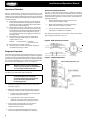
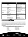
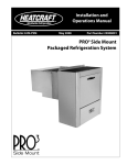
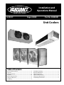
Installation and
Operations Manual
H-IM-UC
August 2008
Part No. 25008201
Replaces None. Information formerly included in H-IM-64L
Unit Coolers
Table of Contents
General Safety Information................................................................... 2
Inspection................................................................................................. 2
Warranty Statement................................................................................ 2
Placement..............................................................................................3-4
Defrost Troubleshooting........................................................................ 4
Condensate Drain Lines......................................................................... 5
Field Wiring............................................................................................... 5
H-IM-UC-0808 | Version 000
Check Out and Start Up.......................................................................... 5
Operational Check Out........................................................................... 6
Evaporator Superheat............................................................................ 6
Expansion Valve Selection..................................................................... 7
Evaporator Troubleshooting................................................................. 8
InterLink Replacement Parts................................................................. 8
Installation and Operations Manual
General Safety Information
1. Installation and maintenance to be performed only
by qualified personnel who are familiar with this type
of equipment
2. Some units are pressurized with dry air or inert gas.
All units must be evacuated before charging the system with refrigerant.
3. Make sure that all field wiring conforms to the requirements
of the equipment and all applicable national and local codes.
4. Avoid contact with sharp edges and coil surfaces.
They are a potential injury hazard.
5. Make sure all power sources are disconnected before any service work is done on units.
WARNING: Refrigerant can be harmful if it is inhaled. Refrigerant must be used and recovered responsibly.
Failure to follow this warning may result in personal injury or death.
Inspection
Responsibility should be assigned to a dependable individual at the
job site to receive material. Each shipment should be carefully checked
against the bill of lading. The shipping receipt should not be signed
until all items listed on the bill of lading have been accounted. Check
carefully for concealed damage. Any shortage or damages should
be reported to the delivering carrier. Damaged material becomes the
delivering carrier’s responsibility, and should not be returned to the
manufacturer unless prior approval is given to do so. When uncrating,
care should be taken to prevent damage. Heavy equipment should be
left on its shipping base until it has been moved to the final location.
Check the serial tag information with invoice. Report any discrepancies
to your Heatcraft Refrigeration Products Sales Representative.
Warranty Statement
Seller warrants to its direct purchasers that products, including Service
Parts, manufactured by SELLER shall be of a merchantable quality, free
of defects in material or workmanship, under normal use and service
for a period of one (1) year from date of original installation, or
eighteen (18) months from date of shipment by SELLER, whichever
first occurs. Any product covered by this order found to Seller’s
satisfaction to be defective upon examination at Seller’s factory will
at SELLER’s option, be repaired or replaced and returned to Buyer
via lowest common carrier, or SELLER may at its option grant Buyer
a credit for the purchase price of the defective article. Upon return
of a defective product to SELLER’s plant, freight prepaid, by Buyer,
correction of such defect by repair or replacement, and return freight
via lowest common carrier, shall constitute full performance by SELLER
of its obligations hereunder.
SELLER shall have no liability for expenses incurred for repairs made by
Buyer except by prior, written authorization. Every claim on account
of breach of warranty shall be made to SELLER in writing within the
warranty period specified above – otherwise such claim shall be
deemed waived. Seller shall have no warranty obligation whatsoever
if its products have been subjected to alteration, misuse, negligence,
free chemicals in system, corrosive atmosphere, accident, or if
operation is contrary to SELLER’s or manufacturer’s recommendations,
or if the serial number has been altered, defaced, or removed.
Seller makes no express warranties except as noted above. All implied
warranties are limited to the duration of the Express Warranty. Liability
for incidental and consequential damages is excluded.
The forgoing is in lieu of all other warranties, express or implied,
notwithstanding the provisions of the uniform commercial code, the
Magnuson-Moss Warranty - Federal Trade Commission Improvement
Act, or any other statutory or common law, federal or state.
SELLER makes no warranty, express or implied, of fitness for any
particular purpose, or of any nature whatsoever, with respect
to products manufactures or sold by seller hereunder, except as
specifically set forth above and on the face hereof. It is expressly
understood and agreed that SELLER shall not be liable to buyer,
or any customer of buyer, for direct or indirect, special, incidental,
consequential or penal damages, or for any expenses incurred by
reason of the use or misuse by buyer or third parties of said products.
To the extent said products may be considered "consumer products,"
As defined in Sec. 101 of the Magnuson-Moss Warranty - Federal
Trade Commission Improvement Act, SELLER makes no warranty of
any kind, express or implied, to "consumers," except as specifically set
forth above and on the face hereof.
The following conditions should be adhered to when installing
this unit to maintain the manufacturers warranty:
(a)
(b)
System piping must be in accordance with good
refrigeration practices.
Inert gas must be charged into the piping during brazing.
(c)
The power supply to the unit must meet the following conditions:
A. Three phase voltages must be +/
10% of nameplate ratings. Single
phase must be within +10% or
-5% of nameplate ratings.
B. Phase imbalance cannot exceed 2%.
(d) All control and safety switch circuits must be properly connected according to the wiring diagram.
(e) The factory installed wiring and piping must not be changed without written factory approval.
(f )
All equipment is installed in accordance with Heatcraft Refrigeration Products specified minimum clearances.
© 2008 Heatcraft Refrigeration Products LLC
Unit Coolers
Recommended Unit Cooler Placement
Some general rules for evaporator placement which must be
followed are:
1.
2.
3.
4.
5.
The air pattern must cover the entire room.
NEVER locate evaporators over doors.
Location of aisles, racks, etc. must be known.
Location relative to compressors for minimum pipe runs.
Location of condensate drains for minimum run.
The size and shape of the storage will generally determine the
type and number of evaporators to be used and their location.
The following are some typical examples:
NOTE: Leave space equal to unit height between bottom of unit
and product. Do not stack product in front of fans.
Minimum Unit Clearances
Figure 1. Medium Profile and Large Unit Coolers
NOTE:
W = Total width
of evaporator
coil surface.
Two evaporators
One evaporator
Figure 2. Low Profile Unit Coolers
NOTE:
H = Total height
of evaporator
coil surface.
Two evaporators
One evaporator
Figure 3. Center Mount Unit Coolers
Recommended Maximum - Minimum Dimensions for
Center Mount Unit Cooler Installations.
E
S
M
T
Max. Min. Max. Min. Max. Min. Max. Min.
25'
2'
20'
3'
40'
3'
40'
6'
Installation and Operations Manual
Unit Cooler Mounting
Most evaporators can be mounted with rod hangers, lag screws, or
bolts. Use 5/16" bolt and washers or rod for up to 250 pounds, 3/8"
for up to 600 pounds and 5/8" for over 600 pounds. Care should be
taken to mount the units level so that condensate drains properly.
Note that some unit cooler designs achieve drain pan slope by using
different height mounting brackets. In this situation, the top of the
mounting brackets should be level. Adequate support must be
provided to hold the weight of the unit.
When using rod hangers, allow adequate space between the top of
the unit and the ceiling for cleaning. To comply with NSF Standard 7,
the area above the unit cooler must be sealed or exposed in such a way
to facilitate hand cleaning without the use of tools. When lagging or
bolting the unit flush to the ceiling, seal the joint between the top and
the ceiling with an NSF listed sealant and ends of open hanger channels
must be sealed to prevent accumulation of foreign matter.
When locating unit coolers in a cooler or freezer, refer to Figures 1
through 4 for guidelines.
NOTE: Always avoid placement of Unit Coolers direct above
doors and door openings.
Figure 4. Large Coolers and Freezers Placement.
Cooler or Freezers
where one wall will not
accommodate all required
evaporators or where air
throw distance must be
considered.
Where one wall evaporator
mounting is satisfactory.
Cooler or Freezer with Glass
Display Doors
Baffled Unit - Allow sufficient
space between rear of Unit Cooler
and wall to permit free return of
air. Refer to Figures 1 through 3
(page 3) for proper space.
Baffle
Glass
Display
Door
Elevation view of glass display
door cooler or freezer. Be sure
air discharge blows above, not
directly at doors. Provide baffle if
door extends above blower level.
Defrost Troubleshooting Fan Motor
If the motor does not operate or it cycles on thermal overload, remove
motor leads from terminal block and apply correct voltage across the
leads. If motor still does not operate satisfactorily, it must be replaced.
Before starting the unit, rotate fan blades to make sure they turn freely
and have sufficient clearance.
Fan Delay & Defrost Termination Control
This control is a single pole double throw switch. The red lead wire
is wired to common. The black wire is wired in series with the fan
motors. The brown wire is wired in series with the defrost termination
solenoid in the timer. The brown and red contacts close and the black
and red contacts open when the temperature is above 55ºF. The black
and red contacts close and the brown and red contacts open when
the temperature is below 35ºF.
On initial “pull down” of a warm box the fan will not start until
the coil temperature reaches approximately 35ºF. If the box is still
comparatively warm (60ºF) when the fan starts, then blowing this
warm air over the coil may cause it to warm up to 55ºF and thus stop
the fan. Therefore, the fan may recycle on initial “pull down.” This
control cannot be adjusted.
If the fan motor fails to start when the control is below 35ºF, disconnect
the fan motor leads and check the motor as described for fan motors.
Also check whether current is being supplied at “N” and “4” from the
timer. The fan delay control must be below 35ºF when checking for
a closed circuit.
Defrost Heater
If unit shows very little or no defrosting and does not heat, disconnect
heater and check to find if it is burned out. To test, apply correct voltage
across heater or use continuity flashlight battery tester.
Drain Pan
If drain pan has an ice build-up, drain line may be frozen. The
drain line should be pitched sharply and exit cabinet as quickly as
possible. Sometimes location and ambient at the drain outside of
cabinet may cause freeze-up. A drain line heater may be required
to correct the freeze-up. Any traps in the drain line must be located
in a warm ambient.
Unit Coolers
Condensate Drain Lines
Field Wiring
Either copper or steel drain lines should be used and properly protected
from freezing. In running drain lines, provide a minimum 1/4 inch per
foot pitch for proper drainage. Drain lines should be at least as large
as the evaporator drain connection. All plumbing connections should
be made in accordance with local plumbing codes. All condensate
drain lines must be trapped, and run to an open drain. They must
never be connected directly to the sewer system. Traps in the drain
line must be located in a warm ambient. We recommend a trap on
each evaporator drain line prior to any tee connections. Traps located
outside, or extensive outside runs of drain line must be wrapped with
a drain line heater. The heater should be connected so that it operates
continuously. It is recommended that the drain line be insulated to
prevent heat loss. A heat input of 20 watts per linear foot of drain line
for 0˚F (-18˚C) room applications and 30 watts per linear foot for -20˚F
(-29˚C) rooms is satisfactory. In freezers, the evaporator drain pan fitting
should be included when heating and insulating the drain line.
The field wiring should enter the areas as provided on the unit. The
wiring diagram for each unit is located on the inside of the electrical
panel door. All field wiring should be done in a professional manner
and in accordance with all governing codes. Before operating unit,
double check all wiring connections, including the factory terminals.
Factory connections can vibrate loose during shipment.
Inspect drain pan periodically to insure free drainage of condensate.
If drain pan contains standing water, check for proper installation. The
drain pan should be cleaned regularly with warm soapy water.
4.
5.
WARNING: All power must be disconnected before cleaning. Drain pan also serves as cover of hazardous moving parts. Operation of unit without
drain pan constitutes a hazard.
6.
Traps on low temperature units must be outside of refrigerated
enclosures. Traps subject to freezing temperatures must be wrapped
with heat tape and insulated.
NOTE: Always trap single evaporator system drain
lines individually to prevent humidity migration.
Figure 5. Condensate Drain Lines
DRAIN LINE MIN.
PITCH - 1/4”/ FT.
VAPOR SEAL
WARNING:
1.
2.
3.
7.
All wiring must be done in accordance with
applicable codes and local ordinances.
The serial data tag on the unit is marked with the electrical
characteristic for wiring the unit.
Consult the wiring diagram in the unit cooler and in the condensing unit for proper connections.
Wire type should be of copper conductor only and of the
proper size to handle the connected load.
The unit must be grounded.
For multiple evaporator systems, the defrost termination
controls should be wired in series. Follow the wiring diagrams
for multiple evaporator systems carefully. This will assure
complete defrost of all evaporators in the system.
Multiple evaporator systems should operate off of one thermostat.
If a remote defrost timer is to be used, the timer should be
located outside the refrigerated space.
Check Out and Start Up
NOTE: All adjustable controls and valves must be field
adjusted to meet desired operation. There are no
factory preset controls or valve adjustments. This
includes low pressure, high pressure, adjustable
head pressure systems and expansion valves.
After the installation has been completed, the following points should
be covered before the system is placed in operation:
(a) Check all electrical and refrigerant connections.
Be sure they are all tight.
(b) Check the room thermostat for normal operation and adjust.
(c) Wiring diagrams, instruction bulletins, etc. attached to the condensing units should be read and filed for future reference.
(d) All fan motors on evaporators should be checked for proper rotation. Fan motor mounts should be carefully checked for tightness and proper alignment.
(e) Electric and hot gas evaporator fan motors should be temporarily wired for continuous operation until the room temperature has stabilized.
(f ) Do not leave unit unattended until the system has reached normal operating conditions and the oil charge has been properly adjusted to maintain the oil
level between 1/4 and bottom of the sight glass.
(g) Make sure all Schrader valve caps are in place and tight.
TRAP
OPEN
DRAIN
Installation and Operations Manual
Operational Check Out
After the system has been charged and has operated for at least
two hours at normal operating conditions without any indication of
malfunction, it should be allowed to operate overnight on automatic
controls. Then a thorough recheck of the evaporator operation should
be made as follows:
(a) Check liquid line sight glass and expansion valve operation.
If there are indications that more refrigerant is required, leak test all connections and system components and repair
any leaks before adding refrigerant.
(b) Thermostatic expansion valves must be checked for
proper superheat settings. Feeler bulbs must be in positive
contact with the suction line and should be insulated. Valves
set at high superheat will lower refrigeration capacity. Low superheat promotes liquid slugging and compressor
bearing washout.
(c) Check defrost controls for initiation and termination settings, and length of defrost period. Set fail safe at length of defrost + 25%.
Example: 20 minute defrost + 5 minutes
= 25 minute fail safe
(d) Check drain pan for proper drainage.
(e) Install instruction card and control system diagram for use of building manager or owner.
Alternative Superheat Method
The most accurate method of measuring superheat is found by
following the previous procedure, Temperature/Pressure method.
However, that method may not always be practical. An alternative
method which will yield fairly accurate results is the temperature /
temperature method:
1. Measure the temperature of the suction line at the point the bulb is clamped (outlet).
2.
Measure the temperature of one of the distributor tubes close to the evaporator coil (inlet).
3.
Subtract the inlet temperature from the outlet temperature. The difference is Superheat.
This method will yield fairly accurate results as long as the pressure
drop through the evaporator coil is low.
Figure 6. Bulb and Contact Location
Evaporator Superheat
Check Your Superheat. After the box temperature has reached or is
close to reaching the desired temperature, the evaporator superheat
should be checked and adjustments made if necessary. Generally,
systems with a design TD of 10˚F should have a superheat value of 6˚
to 10˚F for maximum efficiency. For systems operating at higher TD’s,
the superheat can be adjusted to 12˚ to 15˚ ˚F as required.
NOTE:
Minimum compressor suction superheat of 20˚F may override these recommendations
on some systems with short line runs.
To properly determine the superheat of the evaporator, the following
procedure is the method Heatcraft recommends:
WARNING:
If the condensing unit has no flooded
condenser head pressure control, the
condensing unit must have the discharge
pressure above the equivalent 105˚F
condensing pressure.
1. Measure the temperature of the suction line at the point the bulb is clamped.
2. Obtain the suction pressure that exists in the suction line at the bulb location by either of the following methods:
a. A gauge in the external equalized line will indicate the pressure directly and accurately.
b. A gauge directly in the suction line near the evaporator or directly in the suction header of the evaporator will yield the same reading as 2a above.
3. Convert the pressure obtained in 2a or 2b above to
saturated evaporator temperature by using a
temperature-pressure chart.
4. Subtract the saturated temperature from the actual suction line temperature. The difference is Superheat.
Figure 7. Multiple Evaporators
Unit Coolers
Table 1. Expansion Valve Selection For 100# Head Pressure Valve
BTUH at about
10° T.D.
3,000-5,000
5,500-7000
7500-8000
8500-10,000
10,500-11,000
11,500-13,000
13,500-15,000
15,500-17,000
17,500-20,000
20,500-24,000
24,500-28,000
28,500-34,000
34,500-40,000
40,500-50,000
50,500-60,000
60,500-70,000
70,500-80,000
80,500-90,000
90,500-100,000
100,500-110,000
110,500-120,000
120,500-130,000
R-507/R404A
-20˚F/-29˚C Evap.
Sporlan
ALCO
EGSE 1/2 ZP
HFESC-1/2-RZ
EGSE 1/2 ZP
HFESC-1/2-RZ
EGSE 1 ZP
HFESC-1/2-RZ
EGSE 1 ZP
HFESC-1-RZ
EGSE 1 ZP
HFESC-1 1/4-RZ
EGSE 11/2 ZP HFESC-1 1/2-RZ
EGSE 11/2 ZP
HFESC-2-RZ
EGSE 2 ZP
HFESC-2-RZ
EGSE 2 ZP
HFESC-3 1/2-RZ
SSE 3 ZP
HFESC-3 1/2-RZ
SSE 3 ZP
HFESC-3 1/2-RZ
SSE 4 ZP
HFESC-5-RZ
OSE 6 ZP
HFESC-5-RZ
OSE 8 ZP
HFESC-7-RZ
OSE 9 ZP
HFESC-10-RZ
OSE 9 ZP
HFESC-10-RZ
OSE 12 ZP
HFESC-10-RZ
OSE 12 ZP
HFESC-13-RZ
OSE 12 ZP
HFESC-13-RZ
OSE 21 ZP
TRAE-20-RZ
OSE 21 ZP
TRAE-20-RZ
OSE 21 ZP
TRAE-20-RZ
R-507/R404A +25˚F/-4˚C Evap.
Sporlan
ALCO
EGSE 1/2 C
HFESC-1/2-RC
EGSE 1 C
HFESC-1/2-RC
EGSE 1 C
HFESC-1-RC
EGSE 11/2 C HFESC-1 1/4-RC
EGSE 11/2 C HFESC-1 1/4-RC
EGSE 11/2 C HFESC-1 1/4-RC
EGSE 2 C
HFESC-1 1/2-RC
EGSE 2 C
HFESC-2-RC
SSE 3 C
HFESC-2-RC
SSE 3 C
HFESC-3-RC
SSE 4 C
HFESC-3-RC
SSE 4 C
HFESC-3-RC
SSE 6 C
HFESC-5-RC
OSE 8 C
HFESC-5-RC
OSE 9 C
HFESC-7-RC
OSE 9 C
HFESC-10-RC
OSE 12 C
HFESC-10-RC
OSE 12 C
HFESC-10-RC
OSE 12 C
HFESC-13-RC
OSE 21 C
HFESC-13-RC
OSE 21 C
HFESC-13-RC
OSE 21 C
TRAE-20-RC
R-22
-20˚F/-29˚C Evap.
Sporlan
ALCO
EGVE 1/2 Z
HFESC-1-HZ
EGVE 1 ZP
HFESC-1-HZ
EGVE 1 ZP
HFESC-1 1/2-HZ
EGVE 11/2 ZP HFESC-1 1/2-HZ
EGVE 11/2 ZP
HFESC-2-HZ
EGVE 11/2 ZP
HFESC-2-HZ
EGVE 2 ZP
HFESC-2 1/2-HZ
EGVE 2 ZP
HFESC-2 1/2-HZ
EGVE 3 ZP
HFESC-3-HZ
SVE 3 ZP
HFESC-3-HZ
SVE 4 ZP
HFESC-5 1/2-HZ
SVE 5 ZP
HFESC-5 1/2-HZ
SVE 8 ZP
HFESC-5 1/2-HZ
SVE 10 ZP
HFESC-8-HZ
SVE 10 ZP
HFESC-8-HZ
OVE 15 ZP
HFESC-10-HZ
OVE 15 ZP
HFESC-15-HZ
OVE 15 ZP
HFESC-15-HZ
OVE 15 ZP
HFESC-15-HZ
OVE 20 ZP
HFESC-20-HZ
OVE 20 ZP
HFESC-20-HZ
OVE 20 ZP
HFESC-20-HZ
R-22
+25˚F/-4˚C Evap.
Sporlan
ALCO
EGVE 1/2 C
HFESC-1/2-HC
EGVE 1 C
HFESC-1-HC
EGVE 1 C
HFESC-1-HC
EGVE 1 C
HFESC-1-HC
EGVE 11/2 C
HFESC-1-HC
EGVE 11/2 C
HFESC-1-HC
EGVE 11/2 C
HFESC-2-HC
EGVE 2 C
HFESC-2-HC
EGVE 2 C
HFESC-2 1/2-HC
SVE 3 C
HFESC-3-HC
SVE 3 C
HFESC-3-HC
SVE 4 C
HFESC-5 1/2-HC
SVE 4 C
HFESC-5 1/2-HC
SVE 5 C
HFESC-5 1/2-HC
SVE 8 C
HFESC-8-HC
SVE 8 C
HFESC-8-HC
SVE 10 C
HFESC-10-HC
SVE 10 C
HFESC-10-HC
OVE 15 C
HFESC-15-HC
OVE 15 C
HFESC-15-HC
OVE 15 C
HFESC-15-HC
OVE 15 C
HFESC-15-HC
R-22
-20˚F/-29˚C Evap.
Sporlan
ALCO
EGVE 1/2 ZP
HFESC-1/2-HZ
EGVE 1 ZP
HFESC-1-HZ
EGVE 1 ZP
HFESC-1-HZ
EGVE11/2 ZP HFESC-1 1/2-HZ
EGVE 11/2 ZP HFESC-1 1/2-HZ
EGVE 11/2 ZP
HFESC-2-HZ
EGVE 2 ZP
HFESC-2-HZ
EGVE 2 ZP
HFESC-2 1/2-HZ
EGVE 3 ZP
HFESC-2 1/2-HZ
SVE 3 ZP
HFESC-3-HZ
SVE 4 ZP
HFESC-3-HZ
SVE 4 ZP
HFESC-5 1/2-HZ
SVE 5 ZP
HFESC-5 1/2-HZ
SVE 8 ZP
HFESC-5 1/2-HZ
SVE 10 ZP
HFESC-8-HZ
OVE 15 ZP
HFESC-8-HZ
OVE 15 ZP
HFESC-10-HZ
OVE 15 ZP
HFESC-10-HZ
OVE 15 ZP
HFESC-15-HZ
OVE 20 ZP
HFESC-15-HZ
OVE 20 ZP
HFESC-15-HZ
OVE 20 ZP
HFESC-15-HZ
R-22
+25˚F/-4˚C Evap.
Sporlan
ALCO
EGVE 1/2 C
HFESC-1/2-HC
EGVE 1/2 C
HFESC-1-HC
EGVE 1 C
HFESC-1-HC
EGVE 1 C
HFESC-1-HC
EGVE 1 C
HFESC-1-HC
EGVE 1 C
HFESC-1 1/2-HC
EGVE 11/2 C HFESC-1 1/2-HC
EGVE 11/2 C HFESC-1 1/2-HC
EGVE 11/2 C
HFESC-2-HC
SVE 2 C
HFESC-2-HC
SVE 3 C
HFESC-2 1/2-HC
SVE 3 C
HFESC-3-HC
SVE 3 C
HFESC-3-HC
SVE 4 C
HFESC-5 1/2-HC
SVE 5 C
HFESC-5 1/2-HC
SVE 5 C
HFESC-5 1/2-HC
SVE 8 C
HFESC-8-HC
SVE 8 C
HFESC-8-HC
SVE 10 C
HFESC-8-HC
SVE 10 C
HFESC-10-HC
SVE 10 C
HFESC-10-HC
OVE 15 C
HFESC-10-HC
NOTES:
1. Valve selections assume standard conditions and 100°F vapor-free liquid.
2. Equivalent valve may be used in place of selection.
3. For "Medium Temp R-507," valve designation will use “P” for refrigerant code.
Table 2. Expansion Valve Selection 180# Head Pressure Valve
BTUH at about
10° T.D.
3,000-5,000
5,500-7000
7500-8000
8500-10,000
10,500-11,000
11,500-13,000
13,500-15,000
15,500-17,000
17,500-20,000
20,500-24,000
24,500-28,000
28,500-34,000
34,500-40,000
40,500-50,000
50,500-60,000
60,500-70,000
70,500-80,000
80,500-90,000
90,500-100,000
100,500-110,000
110,500-120,000
120,500-130,000
R-507/R404A
-20˚F/-29˚C Evap.
Sporlan
ALCO
EGSE 1/2 ZP
HFESC-1/2-RZ
EGSE 1/2 ZP
HFESC-1-RZ
EGSE 1 ZP
HFESC-1-RZ
EGSE 1 ZP
HFESC-1-RZ
EGSE 1 ZP
HFESC-1 1/4-RZ
EGSE 1 1/2 ZP HFESC-1 1/4-RZ
EGSE 2 ZP
HFESC-1 1/2-RZ
EGSE 2 ZP
HFESC-2-RZ
EGSE 2 ZP
HFESC-2-RZ
SSE 3 ZP
HFESC-3-RZ
SSE 4 ZP
HFESC-3-RZ
SSE 4 ZP
HFESC-5-RZ
SSE 6 ZP
HFESC-5-RZ
OSE 9 ZP
HFESC-7-RZ
OSE 9 ZP
HFESC-7-RZ
OSE 9 ZP
HFESC-10-RZ
OSE 12 ZP
HFESC-10-RZ
OSE 12 ZP
HFESC-10-RZ
OSE 12 ZP
HFESC-13-RZ
OSE 12 ZP
HFESC-13-RZ
OSE 12 ZP
HFESC-13-RZ
OSE 21 ZP
HFESC-13-RZ
R-507/R404A +25˚F/-4˚C Evap.
Sporlan
ALCO
EGSE 1/2 C
HFESC-1/2-RC
EGSE 1 C
HFESC-1/2-RC
EGSE 1 C
HFESC-1/2-RC
EGSE 1 C
HFESC-1-RC
EGSE 11/2 C
HFESC-1-RC
EGSE 11/2 C HFESC-1 1/4-RC
EGSE 11/2 C HFESC-1 1/4-RC
EGSE 2 C
HFESC-1 1/2-RC
EGSE 2 C
HFESC-1 1/2-RC
SSE 3 C
HFESC-2-RC
SSE 3 C
HFESC-2-RC
SSE 4 C
HFESC-3 1/2-RC
SSE 6 C
HFESC-3 1/2-RC
SSE 6 C
HFESC-3 1/2-RC
OSE 9 C
HFESC-5-RC
OSE 9 C
HFESC-7-RC
OSE 12 C
HFESC-7-RC
OSE 12 C
HFESC-10-RC
OSE 12 C
HFESC-10-RC
OSE 12 C
HFESC-10-RC
OSE 12 C
HFESC-10-RC
OSE 12 C
HFESC-13-RC
Table 3. Evaporator Troubleshooting Chart
SYMPTOMS
POSSIBLE CAUSES
POSSIBLE CORRECTIVE STEPS
Fan(s) will not operate.
1.Main switch open.
2.Blown fuses.
3.Defective motor.
4.Defective timer or defrost thermostat.
5.Unit in defrost cycle.
6.Coil does not get cold enough to reset thermostat.
1.Close switch.
2. Replace fuses. Check for short circuits or overload conditions.
3.Replace motor.
4.Replace defective component.
5.Wait for completion of cycle.
6.Adjust fan delay setting of thermostat. See Defrost
Thermostat Section of this bulletin.
Room temperature too high.
1.Room thermostat set too high.
2.Superheat too high.
3.System low on refrigerant.
4.Coil iced-up.
5.Unit cooler located too close to doors.
6.Heavy air infiltration.
1.Adjust thermostat.
2.Adjust thermal expansion valve.
3.Add refrigerant.
4. Manually defrost coil. Check defrost controls for malfunction.
5.Relocate unit cooler or add strip curtain to door opening.
6.Seal unwanted openings in room.
Ice accumulating on ceiling
around evaporator and/or on
fan guards venturi or blades.
1.Defrost duration is too long.
2.Fan delay not delaying fans after defrost period.
3.Defective defrost thermostat or timer.
4.Too many defrosts.
1.Adjust defrost termination thermostat.
2.Defective defrost thermostat or not adjusted properly.
3.Replace defective component.
4.Reduce number of defrosts.
Coil not clearing of frost during
defrost cycle.
1.Coil temperature not getting above freezing point
during defrost.
2.Not enough defrost cycles per day.
3.Defrost cycle too short.
4.Defective timer or defrost thermostat.
1.Check heater operation.
Ice accumulating in drain pan
1.Defective heater.
2.Unit not pitched properly.
3.Drain line plugged.
4.Defective drain line heater.
5. Defective timer or thermostat.
1.Replace heater.
2.Check and adjust if necessary.
3.Clean drain line.
4.Replace heater.
5.Replace defective component.
Uneven coil frosting
1.Defective heater.
2.Located too close to door or opening.
3.Defrost termination set too low.
4.Incorrect or missing distributor nozzle.
1.Replace heater.
2.Relocate evaporator.
3.Adjust defrost termination setting higher.
4.Add or replace nozzle with appropriately sized
orif ice for conditions.
2.Adjust timer for more defrost cycles.
3.Adjust defrost thermostat or timer for longer cycle.
4.Replace defective component.
Replacement Parts by
Commercial Refrigeration Parts
InterLink is your link to a complete line of dependable and certified commercial refrigeration parts, accessories and innovative electronic controls for all Heatcraft
Refrigeration Products (HRP) brands - including Bohn, Larkin, Climate Control and Chandler. At InterLink, we provide our wholesalers with a comprehensive
selection of product solutions and innovative technologies for the installed customer base. And every product is built to ensure the same high performance
standards with which all HRP brands are built — backed by a dedicated team to serve every customer need, delivering at the best lead times in the industry.
Replacement parts should be obtained from your local InterLink wholesaler. Replacement parts, which are covered under the terms of the warranty statement
on page 2 of this manual, will be reimbursed for total part cost only. The original invoice from the parts supplier must accompany all warranty claims for
replacement part reimbursement. Heatcraft Refrigeration Products reserves the right to adjust the compensation amount paid on any parts submitted
for warranty reimbursement when a parts supplier's original invoice is not provided with a claim. For more information, call 800-686-7278 or visit
www.interlinkparts.com.
For more detailed information on the following topics, please visit http://heatcraftrpd.com/service/publibrary.asp
for our complete Refrigeration Systems Installation and Operation Manual (H-IM-64L).
Defrost Thermostat
Expansion Valves & Nozzles
Refrigerant Oils
Recommended Refrigerant Piping Practices
Line Sizing Charts
Hot Gas Defrost Systems
Evacuation and Leak Detection
Refrigerant Charging Instructions
System Balancing — Compressor Superheat
General Sequence and Operation
Troubleshooting Guides
Preventive Maintenance Guidelines
Typical Wiring Diagrams
Since product improvement is a continuing effort, we reserve the right to make changes in specifications without notice.
The name behind the brands you trust.™
CLIMATE
CONTROL
H-IM-UC-0808
Commercial Refrigeration Parts