1
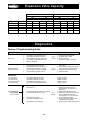
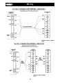
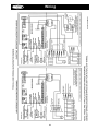
™
H-IM-79D
February, 2004
Part Number 25001401
Replaces H-IM-79C (12/03)
Installation & Operation
Manual
Index
Beacon II Board layout ........................................................................................................ 3
Installation Tips ................................................................................................................... 4
Brazing
Power Supply
Wiring .............................................................................................................................. 5
Multiple Evaporator Configuration ....................................................................................... 6
Box Temperature control setting
Leak Testing
Refrigerant Charging ........................................................................................................... 7
Start Up Operation ......................................................................................................... 8-11
Operating Mode Display .................................................................................................... 11
Programming and reviewing settings and changes ....................................................... 12-13
Program review button
Select button
Enter button
Monitoring Items ............................................................................................................... 14
Monitor button
Force Defrost button
Force Service button
Reset Time button
Clear/Test button
Locking Beacon II board .................................................................................................... 15
Status Indicator LED .................................................................................................... 15-16
Low Ambient Operation ..................................................................................................... 16
Pumpdown ................................................................................................................... 16-17
Defrost ....................................................................................................................... 17-18
Alarms ............................................................................................................................ 18
Error Indicator
Evaporator fans shutdown by operators ............................................................................ 19
Checking Operation of Expansion valve ....................................................................... 20-21
Power Failures
Service Mode
Spare Sensor Terminals
Checking sensors ............................................................................................................. 21
Sensor resistance/temperature table
System Defaults ................................................................................................................ 22
Parts List
Operational limits .............................................................................................................. 23
Expansion Valve Capacity
Diagnostics .................................................................................................................. 24-27
Wiring diagrams ........................................................................................................... 28-33
Preventive Maintenance .................................................................................................... 34
Service Record ............................................................................................................ 35-36
2
Beacon II Board Layout
BEACON II BOARD
Heater
Relay
Expansion
Valve
Connection
Fan
Relay
LED
Display
Selection
Buttons
Room
Sensor
Defrost
Sensor
24V
Terminal
Block
Suction
Sensor
Suction
Pressure
© 2004, Heatcraft Refrigeration Products LLC
3
Installation
Installation Tips
•
•
•
•
•
•
•
•
•
•
•
Use a minimum 18 gauge wire for all low voltage connections.
The Beacon II board gets its 24 VAC power supply from a transformer mounted in the
electrical end of each evaporator. On 208-240 volt systems the multi-tap transformer is
shipped from our factory wired for 240 volts. If your supply voltage is 208 volt you must
change to the 208 volt tap on the transformer.
Note: On multiple evaporators, since a transformer is in each evaporator, the voltage
tap must be set on each evaporator.
Refer to wiring schematic shipped on units for unit wiring. Schematics in this Installation
& Operation Manual are typical wiring schematics only.
Program ALL slave evaporators as SLAVES.
Evaporators are shipped from our factory with a preset box setpoint temperature of 35°F
for air defrost and -10°F for electric defrost. If your box setpoint temperature
requirements are different this must be set using directions outlined under “Room
Temperature Control”.
The suction line temperature sensor MUST be removed from the suction line before
brazing the suction tubing. The sensor MUST then be reinstalled on the suction line
after brazing is completed and the tubing has cooled. Insulate when finished.
The low pressure switch time delay relay, located in the condensing unit, must be set to
1 minute.
If electrical power will be connected prior to evacuation and charging of system, unplug
electric expansion valve from board until system is ready to be evacuated, leak tested
and charged.
Some systems may require the crankcase heater be energized 24 hours prior to startup. The Beacon should be de-energized for this period by placing it in the SERVICE
MODE. This is done by pressing the “FORCE SERVICE” button twice. To start the
system cooling, press the “CLEAR” button.
Room sensors must be left connected on ALL evaporators.
A pressure transducer is installed on the evaporator. Do not leak test system above 150
PSI or damage to transducer could occur. If leak testing must be greater than 150 psig,
disconnect the transducer from he suction header and reconnect after testing is
complete.
CONDENSING UNIT
The condensing unit control panel contains the relays, contactors, time delay and a
terminal block which is appropriately marked to match the low voltage wiring connections. A
sensor for outdoor air temperature measurement is installed on the condensing unit.
Condensing unit must be installed using proper refrigeration practices and codes. Make
sure there is sufficient clearances around unit for adequate air flow and access.
EVAPORATOR UNIT
The evaporator contains the Beacon II controller, electric expansion valve, pressure
transducer, distributor, orifice, transformer and three sensors. These components are all
factory mounted and wired. The three sensors are factory mounted and provide input to the
controller from the following: defrost temp., suction temp., room temp.
Each evaporator unit must be installed using proper refrigeration practices and codes.
Make sure the piping is correctly sized and properly routed. It is highly recommended that
the liquid and suction lines be insulated. There must also be good clearance around unit.
See Heatcraft Refrigeration Installation & Operation Manual for more details.
4
Brazing
Refrigerant Line Brazing ( CAUTION )
The electric expansion valve and the suction temperature sensor on the suction line are
factory installed. Care must be taken when brazing these lines at the evaporator. Too high
a temperature may destroy these components. Heat absorbing compounds or “wet
rags” must be used to protect the electric expansion valve when brazing the
refrigerant line connections. The suction line sensor should be removed before
brazing.
POWER SUPPLY
The Beacon II board gets its 24 VAC power supply from a transformer mounted in the
electrical end of each evaporator. On 208-240 volt systems the multi-tap transformer is
shipped from our factory wired for 240 volts. If your supply voltage is 208 volt you must
change to the 208 volt tap on the transformer.
VERY IMPORTANT: If the supply voltage to the evaporator is 208 volts, the primary tap of
the transformer must be moved to the 208 volt tap. This must be done for all the
evaporators on that system.
If the 24 VAC power supply falls below 18 VAC the system may power down and shut off.
When the power supply is corrected to 24 VAC the system will restart after the four minute
hold-off period and resume normal operation.
On Beacon II systems the main power for the evaporator can be supplied separately from
the power supply of the condensing unit. All wiring, however, must comply with local
electrical codes.
WIRING
Wiring between the condensing unit and the unit cooler(s) will be as follows (see wiring
diagrams):
• High voltage - There may be high voltage on the defrost heater relay and the fan relay.
The evaporator may also be connected to a separate power supply from the condensing
unit. See unit cooler spec. plate for ampacity.
• Low voltage - 24V Class II control circuit. A total of five low voltage leads are required to
connect the condensing unit to the evaporator. (See wiring diagram.) Two of these leads
are for connecting the outdoor temperature sensor. The other three leads are for
connecting the compressor relay, service relay and 24V Common inputs. All 24 volt
wiring must be run separate from the line voltage wiring.
• Low voltage wiring must be 18 gauge minimum. For low voltage wiring, maximum
distances are:
Condensing unit to Master evaporator
500 ft.
Between evaporators
500 ft.
Smart Controller to Master evaporator 1000 ft.
5
Wiring/Configuration
WIRING (cont’d.)
• Multiple units – The multi-in and multi-out are the communication connections.
Connection sequence must follow the multi-out terminal to the multi-in terminal and
the multi-out back to the multi-in terminal in a daisy chain loop.
• Alarm circuit - The onboard alarm is a dry set of NC contacts which closes to indicate an
alarm. The type and wiring for the alarm is customer specified. Note that the alarm
circuit does not distinguish or indicate what has caused the alarm.
• All wiring must comply with all applicable codes and ordinances.
MULTIPLE EVAPORATOR CONFIGURATION (Master/Slave)
If there are multiple evaporators on a system, the program for each SLAVE evaporator
must be changed to identify it as a SLAVE. To do so, press the “PROGRAM REVIEW”
button repeatedly until “SLA” appears then use the “SELECT” knob to select “YES” then
press “ENTER”. All Beacon II boards are shipped with the factory default as a “MASTER”
evaporator. Place all boards in the “Service” mode while you program the setpoints to avoid
errors and alarms which may cause troubles at startup.
VERY IMPORTANT: This must be done for each slave board.
Up to 4 evaporators can be connected as a master/slave configuration. DO NOT remove
the room sensor from any of the Beacon II boards. This also applies when connected
to the optional Smart Controller.
M
S
S
S
CU
M = Master Evaporator
S = Slave Evaporator
CU = Condensing Unit
Each Beacon II board power is supplied by a transformer in the evaporator on which it is
mounted. Do not run any 24 VAC wires between Beacon II boards on the evaporators.
6
Box Temp Control Settings
BOX TEMPERATURE CONTROL SETTINGS
• There is an on board room thermostat on the Beacon II board which can be adjusted
to the desired room temperature. The temperature differential is 2° F.
Temperature Differential
When a system is in the cooling mode and the box setpoint is 35°F, the system will
continue to cool until the box temperature gets to 34°F. At this point the compressor will
pumpdown and shut off. The system will restart cooling when the box temperature has
risen to 36°F.
It is important to note that Beacon II has a minimum 2 minute “ON” time and a minimum
4 minute “OFF” time. This means that the system will run in the cooling mode a
minimum of 2 minutes even if the setpoint temperature is met. In applications where the
system is grossly oversized, the box temperature could go below the differential
temperature before the system cycles off.
In the “OFF” cycle the system will be off for a minimum of 4 minutes even if the box
temperature goes above the differential temperature, before cooling will be restarted.
• The on board room thermostat is factory set at 35°F for Air Defrost systems and
-10°F for electric defrost system.
LEAK TESTING
After all lines are connected, the entire system must be leak tested. The complete system
should be pressurized to not more than 150 psig with refrigerant and dry nitrogen. The use
of an electronic type leak detector is highly recommended because of its greater sensitivity
to small leaks. As a further check it is recommended that this pressure be held for a
minimum of 12 hours and then rechecked. For a satisfactory installation, the system must
be leak tight.
REFRIGERANT CHARGING
Beacon II systems are shipped standard with a head master valve (Scroll compressor
models has a 100 Psi head master valve. All other models have a 180 Psi head master
valve.) The maximum system refrigerant capacity is the receiver capacity as listed in the
sales literature plus the liquid line capacity. Do not add more refrigerant to the system than
90% of the receiver capacity.
7
Start-Up Operation
Start-Up Operation
SINGLE SYSTEM with 1 EVAPORATOR
• Check all wiring connections to be sure they are correct and tight.
• On condensing unit
- Check the setting of Time Delay relay. It should be set at 1 minute (the
second marker).
- Check the Low Pressure switch setting on freezer units. It must be set to 0
PSIG cutout, 10 PSIG cut-in to allow positive start and operation, especially
in cold ambients. This can be changed to a higher value in warmer climates.
On cooler units, the Low Pressure switch has a fixed setting and cannot be
adjusted.
• Turn power on
• On the evaporator
- Use the “PROGRAM REVIEW” button to scroll through settings.
- Check “ rEF ” (Refrigerant Type). Factory defaults are: Air Defrost R-22,
Electric Defrost R-404A. Change to the refrigerant being used.
- Check “bot” (Box Temperature). Factory defaults are: air defrost 35°F and
electric defrost –10°F. Change to the desired temperature.
- Review and change other setting if necessary
- See procedures below on how to change settings.
CU
M
M = Master Evaporator
CU= Condensing unit
8
Start-Up Operation
SINGLE SYSTEM with MULTIPLE EVAPORATORS
•
•
•
•
•
Check all wiring connections to be sure they are correct and tight.
On Condensing unit
- Check the setting of Time Delay relay. It should be set at 1 minute (the
second marker).
- Check the Low Pressure switch setting on freezer units. It must be set to 0
PSIG cutout, 10 PSIG cut-in to allow positive start and operation, especially in
cold ambient. This can be changed to a higher value in warmer climates. On
cooler units, the Low Pressure switch has a fixed setting and cannot be
adjusted.
Turn power on.
On MASTER evaporator
- DO NOT REMOVE the Room Sensor from any evaporator
- Use the “PROGRAM REVIEW” button to scroll through settings.
- Check “rEF” (Refrigerant Type). Factory defaults are: air defrost R-22, electric
defrost R-404A. Change to the refrigerant being used.
- Check “bot” (Box Temperature). Factory defaults are: air defrost 35°F and
electric defrost –10°F. Change to the desired temperature.
- Review and change other setting if necessary.
- See procedures below on how to change settings.
On SLAVE evaporators. All Beacon II boards are shipped with the factory default as
a “MASTER” evaporator.
- DO NOT REMOVE the Room Sensor from any evaporator
- Each SLAVE Evaporator must be changed to identify it as a SLAVE. Use the
“PROGRAM REVIEW” button to scroll until “SLA” appears, then use the
“SELECT” knob to select “YES” then press “ENTER”.
M
S
S
S
CU
M = Master Evaporator
S = Slave Evaporator
9
CU = Condensing Unit
Start-Up Operation
MULTIPLE SYSTEMS with MULTIPLE EVAPORATORS
(Requires a Smart Controller)
• Check all wiring connections to be sure they are correct and tight.
• On condensing units
- Check setting of Time Delay relay. It should be set at 1 minute (the second marker).
- Check the Low Pressure Switch setting on freezer units. It must be set to 0 PSIG
cutout, 10 PSIG cut-in to allow positive start and operation, especially in cold
ambient. This can be changed to a higher value in warmer climates. On cooler units,
the Low Pressure switch has a fixed setting and cannot be adjusted.
• Turn power on.
• On MASTER Evaporator
- DO NOT REMOVE the Room Sensor from any evaporator
• On SLAVE evaporators. All Beacon II boards are shipped with the factory default as a
“MASTER” evaporator.
- Each SLAVE evaporator must be changed to identify it as a SLAVE. Use the
“PROGRAM REVIEW” button to scroll until “SLA” appears, then use the “SELECT”
knob to select “YES” then press “ENTER”.
• Use the Beacon II Smart Controller to set system parameters. See Beacon II Smart
Controller installation instructions for more details.
MULTIPLE SYSTEM CONNECTION
(See Smart Controller instruction manual for more details.)
SYSTEM 1
SYSTEM 2
S
S
S
SYSTEM 3
S
S
S
M
S
CU
M
CU
S
M
S
CU
CU
SMART
CONTROLLER
M
S
S
S
SYSTEM 4
M = Master Evaporator
S = Slave Evaporator
10
CU = Condensing Unit
Start-Up Operation
INITIAL POWER ON
At the initial application of power to the system, the compressor and the evaporator fans
will be in a 4 minute hold-off cycle and will not start immediately. When there is a call for
COOLING, the expansion valve (EEV) opens, then the compressor is started. The
compressor will then run for a minimum of 2 minutes in the “hold-on” cycle. (This means
that the compressor will run for a minimum of 2 minutes before shutting off even if the box
temperature is met.)
The LED alternately displays BOX TEMPERATURE and MODE of operation. On a call for
cooling, dLY will show while the expansion valve is opening. After the compressor starts
the LED will alternately display BOX TEMPERATURE and Coo.
On multiple evaporator systems the MASTER evaporator will display BOX
TEMPERATURE and Coo. The SLAVE evaporators will display Coo only.
When the room thermostat setting is satisfied, and if the compressor ran for at least 2
minutes, the EEV will close and the compressor will pumpdown and shut off. The
evaporator fans will continue to run. The LED will alternately display oFF and BOX
TEMPERATURE.
When the room sensor detects a rise in temperature of approximately 2°F, and the
compressor has been off for at least 4 minutes, the EEV will open to its last position then
the compressor will start. The valve is then adjusted as necessary to obtain the setpoint
superheat setting. During this time, the compressor will run for a minimum 2 minutes “holdon” cycle.
The four minute “Hold-off” can be bypassed and the system started immediately by
pressing the “Reset” button on the Beacon II board.
OPERATING MODE DISPLAY
oFF
Coo
Pdn
dEF
drn
dLY
tSt
SEr
- Off
- Cooling
- Pumpdown
- Defrost
- Draining
- Delay
- Test
- Service
11
Programming & Reviewing
PROGRAMMING AND REVIEWING SETTINGS/CHANGES
The Program Review button is used to program, review and change all program settings
for the system.
Press “PROGRAM REVIEW” button. The Setpoint item will appear on the LED. After a few
seconds delay the Setpoint value will display. Each time the button is pressed a different
setpoint item is displayed.
Next, use the “SELECT” knob to change value of Setpoint Item.
Next, When the desired value is selected, press the “ENTER” button to place it in program
memory. If the “ENTER” button is not pressed the value will not be stored in the memory
and thus will not be changed.
“PROGRAM REVIEW” ITEMS
A-E
rEF
bot
SUP
SLA
dFn
dFF
dFt
dFS
ALH
ALL
ALt
F-C
-
Set Defrost type (Air or ELE)
Set Refrigerant type (R22, R404A or R507)
Set Box temperature (-30°F to +70°F)
Set Superheat (4°F to 20°F)
Set Board as a Slave (Yes or No)
Set Number of defrosts per day (1,2,3,4,5,6,8,10 or 12 per day)
Set Defrost Fail-safe time (10 to 200 minutes)
Set Defrost End temperature (40°F to 100°F)
Set Defrost Delay Start Time (0.5 Hours to 23.5 Hours)
Set Alarm High temperature (-40°F to 90°F)
Set Alarm Low temperature (-40°F to 90°F)
Set Alarm time (2 to 120 minutes)
Set Fahrenheit/Celsius temperature units (°F/°C)
12
Programming & Reviewing
PROGRAMMING AND REVIEWING SETTINGS/CHANGES (cont’d.)
Use the “PROGRAM REVIEW” button to select these items:
•
Defrost Type – “A-E ” - Selection is made for air defrost or electric defrost coil. This will
automatically set the system factory defaults for air defrost and electric defrost. (See
default settings.) Please note that the refrigerant type default for air defrost is R-22 and
for electric defrost it is R404A. All units are shipped with factory defaults settings.
•
Refrigerant Type - “rEF” - Selection for type of refrigerant – R-22, R-404A or R-507.
Default: Air defrost is R-22 and for electric defrost it is R-404A.
•
Box Temperature - “bot” - Select box temperature setpoint. Selection range is -30°F to
+70° F. Defaults: Electric defrost -10°F and air defrost +35°F.
•
Superheat - “SUP” - Evaporator superheat is controlled by the board on each
evaporator. Each board measure the evaporator saturation suction temperature and the
suction pressure to determine the superheat. The superheat value at the evaporator can
be changed to ensure a 20°F to 30°F superheat at the Compressor. Default: 8°F.
•
Evaporator Board: Slave? - “SLA” - On multiple evaporator systems, each evaporator
board has to be programmed to be a Master or a Slave. Each board is shipped from our
factory set as a Master. You must make this change to each Slave evaporator. A
selection of “YES” is made for this setting.
The default for each board is a Master, so on Single Evaporator systems no change is
required.
•
No. of Defrost per Day - “dFn” - A selection must be made for the number of defrosts
cycles per day – 1,2,3,4,5,6,8,10 or 12 per day. If no selection is made, Defaults:
electric defrost 4 per day and air defrost 2 per day.
•
Defrost fail-safe - “dFF” - This is the maximum time allowed for a coil to remain in
defrost. Defrost will be terminated if the defrost end temperature is not attained when
this time has expired. On multiple evaporator systems this is controlled by the Master
unit. Each board should have the same setting. Defaults: electric defrost 30 minutes
and air defrost 40 minutes.
•
Defrost End Temperature - “dFt” - This is the temperature at which the Defrost will be
terminated. Defaults: electric defrost +60°F and air Defrost +45°F.
•
Defrost Delay Start Time - “dFS” - This allows the delay of the start of the first defrost.
Defaults: 0.5 hours to 23.5 hours.
13
Programming & Reviewing
PROGRAMMING AND REVIEWING SETTINGS/CHANGES (cont’d.)
•
Alarm High Temperature - “ALH” - Temperature at which a high box temperature alarm
will be triggered. This does not apply during defrost. Defaults: electric defrost +5°F
and air defrost +50°F.
•
Alarm Low Temperature - “ALL” - Temperature at which a Low Box Temperature alarm
will be triggered. Defaults: Electric Defrost -15°F and Air Defrost +30°F.
•
Alarm Time - “ALt” - Time which High Temperature or Low Temperature condition must
exceed before alarm is triggered. Default: 60 minutes.
•
°F/°C - “F-C” - Select units to display temperature. Fahrenheit or Celsius.
Default: Fahrenheit.
•
When °C is selected a red dot will appear in the right bottom corner of the LED display
of the Beacon II board.
Use the “MONITOR” button to review these items:
SUP
ESP
SCt
SSt
SCP
Odt
dFt
dFS
dFE
AC
SPt
- Superheat (°F/°C)
- Expansion valve steps (0 to 255 steps)
- Suction temperature (°F/°C)
- Saturated Suction temperature (°F/°C)
- Suction pressure at Evaporator (PSIG/HG)
- Outdoor temperature (°F/°C)
- Defrost sensor temperature (°F/°C)
- Time left until next defrost (hours) (on version 1.8 boards)
- Last Defrost Elapsed time (minutes)
- Board Voltage
- Spare Temperature reading
Use this button to “FORCE DEFROST”
To force a defrost , press the “FORCE DEFROST” button. The
system will pumpdown and shut off the compressor. The heaters
are then turned on. The display will show “dEF” and room temp.
Use this button to “RESET TIME”
Pressing this button will reset the time clock in the microprocessor
to zero. At initial power up, pressing this button will bypass the
“four minute” hold-off and the system will start immediately after
the expansion valve opens. This display will show “dLy”.
Use this button to “FORCE SERVICE”
Pressing this button TWICE will cause the system to
pumpdown and the compressor to shut off. The system will
remain off until the “CLEAR” button is pressed. While in the
“FORCE SERVICE”, the LED display will only show “SEr”.
14
Programming & Reviewing
PROGRAMMING AND REVIEWING SETTINGS/CHANGES (cont’d.)
Use this button to “CLEAR/TEST”
Pressing this button ONCE will return the LED display to the default
display. With the system in the OFF mode, pressing and holding
this button will start the “TEST” mode. In the “TEST” mode it will
cycle through each output for 10 seconds. The display will only
show “tst” during “TEST” mode. Test mode will automatically
terminate after 3 sequences.
LOCKING THE BEACON II BOARD
The Beacon II board is lockable to prevent programmed setting changes by unauthorized
personnel. When locked, the program setpoints cannot be changed.
To lock the setting:
• Press “PROGRAM REVIEW” button.
• Press and hold “MONITOR” button.
• While holding “MONITOR” button, press “ENTER” button.
• The LCD will display Loc.
This will prevent unauthorized personnel program changes. To unlock, repeat steps above.
LCD will display “UnL”.
STATUS INDICATOR LED
A RED, three-digit , alphanumeric LED on the Beacon II board indicates status, alarms and
error codes.
LED Display
Box Temp / oFF
Box Temperature/ Mode is displayed
Single Evaporator Multiple Evaporators
Box Temp /Coo
Box Temperature/ Mode is displayed
Master Evap Slave Evaps -
Box Temp / Coo
Coo
Box Temperature/ Mode is displayed
Operating Mode is displayed
• OFF
All Evaporators
• COOLING
• Pumpdown
All Evaporators
Pdn
• DEFROST
All Evaporators
dEF
• TEST
All Evaporators
tSt
• SERVICE
All Evaporators
SEr
• ALARMS
A1
A2
A3
A4
High Box Temp
Low Box temp
System Start-up failure
Compressor pumps down and tries to
restart after 4 minutes.
Input Fault
Box Temp., Suction Temp., Pressure
Transducer open or not installed
15
Status Indicator LED
STATUS INDICATOR LED
• ERRORS
E1
E2
E3
E4
E5
E6
E7
E9
• OTHERS
- Room temperature sensor shorted, open or not installed
- Defrost temperature sensor shorted, open or not
installed
- Suction temperature sensor shorted, open or not
installed
- Suction pressure transducer shorted, open or not
installed
- Outdoor temperature sensor shorted
- Low superheat during cooling
- Compressor shutdown (high or low refrigerant pressure
or low oil pressure)
- Multi-in/Multi-out wiring error
Coo - Room Temperature sensor open or not connected
(Instead of displaying box temperature)
Loc - Board is locked. Settings cannot be changed
UnL - Unlock the board settings
LOW AMBIENT OPERATION
All units are shipped standard with Head Master valves. (Scroll compressor units have a
100 Psi Head Master valve and all other systems have a 180 Psi head master valve.)
Condensing units with multiple condenser fans will have one or more fans cycle on
Pressure Fan Cycling switch.
An adjustable Time Delay relay, factory set at 1 minute, is wired across the Low Pressure
switch (LPS). In cold ambient this allows time for the suction pressure to build up and
prevent nuisance tripping of the LPS.
Pumpdown
At the end of each cooling cycle, when the box temperature is met, the Beacon system will
pump down and shut off the compressor.
To pumpdown, the EEV closes and the compressor runs until one of the following occurs:
•
the Low Pressure Switch opens
•
the suction pressure at the evaporator is 4 psig
•
a total of two minutes has elapsed.
When any of these three conditions occurs the compressor will turn off and not restart until
there is a call for cooling or a periodic pumpdown.
Periodic pumpdown
While in the OFF cycle, if there isn’t a call for cooling (Box setpoint temperature is met) but:
•
the evaporator suction pressure has risen to 10 psig
•
the low pressure switch has closed
The system will initiate pumpdown. This periodic pumpdown will occur at 4 minute intervals
when these two conditions are met.
16
Pumpdown / Defrost
Service Mode
A single pole, single throw switch (SPST) is supplied in each condensing unit for shutting
off the system. Closing the “Service” switch in the condensing unit will cause the system to
pumpdown and shut off. “Ser” will be displayed on the Beacon board LED and “SERVIC” is
displayed on the Smart Controller LCD display. The Evaporator Fan and Heaters will be deenergized in the Service Mode. The system will not restart until the SPST switch is
placed in the “NORMAL” or “OFF” position.
or
A remote “Service” switch can be added to the Beacon II board across the “Ser” and “C”
connections of the terminal block. It will operate in the same manner as the switch above.
or
The system can be pumped down by pressing the “SERVICE” button twice. To restart the
system, press the “CLEAR” button.
or
The system can be pumpdown for service by closing the Liquid line service valve in the
condensing unit, then closing the suction line service valve when the system trips on the
low pressure switch.
In order for air defrost evaporator fan motors to cycle off during “Service” mode, the fan
motors must be wired through the fan relay on the Beacon II board.
Defrost
DEFROST TIMING
When power is first applied to the system, its timer starts counting time. If 4 defrost are
programmed, it will initiate a defrost every 6 hours from when power was first applied.
Beacon II does not have a real time clock. Beacon II does provide the ability to delay the
starting of the first defrost.
DEFROST DELAY START TIME
Example: The system is first powered up at 8:00 AM and is programmed for 4 defrost per
day. The user would like the first defrost at 10:00 AM. To accomplish this, use the
“PROGRAM REVIEW” button to scroll to dFS. Use the “SELECTOR” switch to select 2
hours delay start, then press “ENTER”. The 1st defrost will now occur at 10:00 AM and
then a defrost will occur every 6 hours thereafter.
TIME REMAINING UNTIL NEXT DEFROST (on version 1.8 boards)
To find out how much time is left until the next defrost is scheduled, use the “MONITOR”
button to scroll to dFS. The time displayed will be how much time until the next scheduled
defrost.
DEFROST SCHEDULE IN MEMORY
Beacon II does not have a real time clock but it keeps track of the time that has elapsed in
its memory. It also keeps in memory the number of defrosts scheduled and how much time
has elapsed between defrosts. If a power failure occurs, when power is restored Beacon II
remembers how many defrosts are scheduled and it remembers how much time was left
until the next defrost. It will then defrost based on this timing. So, if the power failure lasted
15 minutes, the defrost schedule will be off by 15 minutes.
RESETTING DEFROST SCHEDULE
When a power interruption causes a severe lag in the defrost schedule, the defrost
schedule can be reset in the following manner. First, press the reset time button on the
board to zero out the internal counters. Then, program the appropriate defrost delay start
time for the next desired defrost period. The defrost schedule will be correct until you have
another power outage.
17
Defrost / Alarms
ELECTRIC DEFROST MODE
When a defrost is initiated, the EEV closes, the compressor is allowed to pumpdown and
shut off. The evaporator fans are cycled off and the defrost heaters are energized.
On multiple evaporator systems, all controllers must terminate their defrost, either on
temperature or fail-safe time, before the master controller will end the defrost cycle.
There is a 2 minute condensate drain-down period after which the compressor is started for
a refreeze period. The evaporator fan stays off (fan delay). The refreeze period will last until
the evaporator suction temperature is at 28°F or 3 minutes has elapsed. After this
sequence, the system is back in the refrigerating mode and evaporators fans are now
running.
AIR DEFROST MODE
The sequence is the same as for electric defrost except that there are no heaters and the
evaporator fans run continuously. If the air defrost for motors are wired through the fan
relay on the board, they will remain energized during defrost mode.
ALARMS
Beacon provides a set of dry contacts for use in signaling an alarm. These contacts can be
connected to a light, a buzzer, a bell etc., which will be activated when an alarm condition
occurs. When the Beacon II is energized, the alarm contacts are OPENED. When an
alarm condition is detected, the contacts are CLOSED.
Conditions under which the alarm contacts will close are:
• High Box Temperature – LED Display: A 1 - Room temperature has exceeded the Alarm
High ALH value for the Alarm time ALt, programmed.
• Low Box Temperature - LED Display: A 2 - Room temperature has dropped below the
Alarm Low ALL value for the Alarm time ALt, programmed
• System Start-up failure – LED Display: A 3 - Compressor pumps down and tries to
restart after 4 minutes. After 4 unsuccessful attempts to restart, the alarm code A 3 is
displayed. System continues trying to restart.
• Input Fault – LED Display: A 4 - Box Temp., Suction Temp., Pressure Transducer open
or not installed.
• Power failure – Loss of power to the Evaporator
ALARM CODES
A1
A2
A3
High Box Temp
Low Box temp
System Start-up failure
A4
Input Fault
Compressor pumps down and tries to restart after
4 minutes
Box Temp., Suction Temp., Pressure
Transducer open or not installed
CLEARING ALARMS
Alarms A1 – High Box Temp. and A2 – Low Box Temp. will clear automatically if the Box
Temp. decreases or increases to below or above the Alarm setpoint temperature. Placing
the system in the “Service Mode” or turning off power will clear the A3 Alarm. Replacing
the Room Sensor, Suction Sensor or Pressure Transducer will clear the A4 Alarm.
18
Error Indicator
ERROR INDICATOR LED
At initial power up, each Beacon board checks for system errors. The system error check
involves checking the various temperature sensors to determine whether any of these
sensors are shorted or open.
The system will pumpdown and cycle off and will not restart until the fault is cleared or
the circuit breaker reset, for the following conditions:
- Suction sensor shorted, open or not installed
- Room temperature sensor shorted or not installed
- Pressure Transducer open or not installed
The system will pumpdown, cycle off and try to restart for these faults. Each try will be
after the 4 minutes “Hold Off” period, for the following fault conditions:
- High pressure or low pressure cutout
- Oil pressure
After the fourth try, the Alarm contacts will be closed and an alarm message displayed on
the LED. To clear this condition, the system should be cycled through the “Service Mode”
after the correction is completed.
ERROR CODES
E1
E2
E3
E4
E5
E6
E7
E9
-
Room temperature sensor shorted, open or not installed
Defrost temperature sensor shorted, open or not installed
Suction temperature sensor shorted, open or not installed
Suction pressure transducer shorted, open or not installed
Outdoor temperature sensor shorted
Low superheat
Compressor shut down (high or low pressure switch open or oil pressure
switch open)
- Multi-in/multi-out wiring error
EVAPORATOR FANS SHUT OFF
In some installations, it is desirable to shut off the evaporator fans periodically. This is easily
accomplished on Beacon II by wiring a single pole, single throw switch (SPST) between the
terminals marked “SERVICE” and “COM” on the Beacon II board. Closing this switch will
cause the system to pumpdown and shut off. Air Defrost fan motors must be wired through
the fan relay on the Beacon II board for this to be effective on Air Defrost systems. The
entire system will be shut off and remain off until the SPST switch is opened.
Air Defrost evaporator fans are setup to run constantly. If there is a need to shut down the
evaporator fans on an Air Defrost system, this can be accomplished by wiring the
evaporator fan motor or evaporator fan motor contactor through the fan relay on the
Beacon II board. When this is done and the Air Defrost system is placed in “SERVICE,” the
evaporator fans will shut off when the system is in pumpdown.
19
Checking Operation of Expansion Valve
CHECKING OPERATION OF EXPANSION VALVE (EEV)
To check if the expansion valve is closing properly:
Install a pressure gauge-set to suction line at the condensing unit. With the system running,
close the valve on the liquid line, at the condensing unit. The system should pumpdown and
shut off on the Low Pressure switch (LPS). If the system does not pumpdown and trip on
the LPS then the compressor valves are weak and needs to be changed.
After the system pumps-down and trip on the LPS, put the system in the service mode. This
will cause the Expansion valve to close.
Open the valve on the liquid line, at the condensing unit. The suction pressure reading on
the gauge set should not increase. If the suction pressure increases then the expansion
valve is leaking and should be changed.
The Expansion valve position can be monitored from the LED display pressing the “MONITOR”
button and scrolling to ESP. This will indicate the number of steps the valve is open.
This can also be checked by using the EXV test pins on the board. This is indicated by a 0 to 5
Volts DC signal. At 0 Volt the valve is closed and at 5 Volts the valve is fully open. At values
between 0 and 5 Volt, the valve will be opened proportionately.
Use the “MONITOR” button to display “SCP”” Evaporator Suction Pressure. Record the
pressure displayed. Start the system and observe the pressure displayed. If the pressure does
not increase, the expansion valve could be defective.
If the system is running, use the “MONITOR” button to display “SCP” Evaporator Suction
Pressure. Record the pressure displayed. While the system is running, press the “FORCE
SERVICE” button. Observe the pressure while the system is pumping down. The pressure
should decrease. If it does not, this indicates a defective valve.
EXPANSION VALVE MOTOR WINDING RESISTANCE
If the expansion valve is suspected of not functioning properly the motor windings
resistance should be measured. This is a bipolar motor with two windings. Measure the
resistance at the pins, on top of the valve, between locations A and B or C and D. (Note
that the pins are not labeled A, B, C, D. This labeling is just for reference. Also, two of the
pins, at location B and location D, have a wider spacing between them than between
location A and C)
Expansion Valve
A• •C
•
B
•
D
Motor Winding
Pins
For valve sizes 29320003 and 29320004, the resistance measured between pin locations A
and B or C and D should be approximately 336 Ohms when the valve is at 75°F.
For valve sizes 29320007, 29320008, 29320013 and 29320014, the resistance measured
between pin locations A and B or C and D should be approximately 116 Ohms when the
valve is at 75°F.
20
Power Failures
Measuring resistance between locations A and C or B and D will always show “Open” because
these locations are between the motor windings.
When the valve is opening or closing, the voltage measured between A and B or C and D
should be between 20 to 22 VAC.
Measuring the DC volt of the EXV TEST pins, on the board, will also indicate if the expansion
valve is open or close. 0 volts DC indicates the valve is closed. 5 volts DC indicates the valve is
fully open. A Values between 0 and 5 volts indicates how much the valve is open or close.
POWER FAILURES
In the event of a power failure Beacon II will automatically close the expansion valve to
prevent refrigerant from migrating throughout the system. After power returns, with 24
VAC at the board, the system will restart in the cooling mode after the four-minute hold
off period.
SPARE SENSOR TERMINALS
Beacon II provides a set of input terminals for customers who may want to monitor an
additional temperature or items such as Product Temperature. This input terminal requires
a signal from a thermistor which meets the temperature/resistance values in Table 1 on
page 22.
If a product temperature simulator is used it must meet the resistance/temperature
specification listed in TABLE 1. The temperature range for this input is –30°F to 140°F.
Sensors on the Beacon system, as supplied, will not simulate product temperature.
This input can be monitored on the LED display by using the “MONITOR” button and
scrolling to SPt. The values displayed will be the temperature of the spare sensor.
CHECKING SENSORS
DO NOT REMOVE SENSORS FROM EVAPORATORS FOR CHECKING.
Use the monitor button to display the value the sensors are reading on the LED (suction
temp. SCt, defrost temp. dFt or room temp.). Compare this value to the measured value
with a thermometer at each of these points. If they do not match, change the sensor.
OR
The sensors can be checked for their proper operation by placing it in a cup of ice water.
Stir the ice water and measure the resistance of the sensor. At 32°F the resistance should
be 32,650 ohms. If it is higher or lower by 5,000 ohms approximately, the sensor should be
replaced.
21
System Defaults
Table 1. Resistance/Temperature Specification
Temperature °F
Ohms
Temperature °F
104
5,320
32
86
8,060
23
77
10,000
14
68
12,490
5
59
15,710
-4
50
19,900
-13
41
25,400
-22
Ohms
32,650
42,330
55,330
72,950
97,070
130,410
176,960
Table 2. System Defaults
PARAMETERS
Refrigerant
Box Temperature
Superheat
Slave Evaporator
No. of Defrost per Day
Defrost Fail-safe time
Defrost End Temperature
Defrost Delay Start Time
Alarm High Temperature
Alarm Low Temperature
Alarm Time
Temperature Units
CODE
AIR
ELECTRIC
rEF
bot
SUP
SLA
dFn
dFF
dFt
dFS
ALH
ALL
ALt
F-C
R-22
35°F
8°F
No
2
40 min.
45°F
0 hrs.
50°F
30°F
60 min.
°F
R-404A
-10°F
8°F
No
4
30 min.
60°F
0 hrs.
5°F
-15°F
60 min.
°F
22
Parts List
Table 3. Parts List
HRPD PART
NUMBER
PART DESCRIPTION
Beacon II Control Board
*Temperature Sensor kit – White Leads
Transformers:
120/24 volt– 40 VA
240/24 volt - 40 VA
460/24 volt – 40 VA
575/24 volt – 40 VA
Pilot Relay
Contactor for Compressor 40 amp with 24 volt Coil
Terminal Block – Condensing Unit
Low Pressure Switch Time Delay Relay
Electric Expansion Valve
ESB 1 – 3/8” x 3/8” Conn
ESB 4 – 3/8” x 3/8” Conn
ESB 10 – 3/8” x 3/8” Conn
ESB 10 – 1/2” x 1/2” Conn
ESB 15 – 7/8” x 1 3/8” Conn
ESB 20 – 7/8” x 1 3/8” Conn
Expansion Valve Molded Connector
(Bipolar valves)
(Unipolar valves)
Pressure Transducer
Pressure Transducer Harness
Beacon II Smart Controller
**Smart Controller Software Package
Beacon II Communications Hub
28910101
89904902
22529601
22529602
22529603
22529701
22511401
2252440
2251266
22536801
29320003
29320004
29320007
29320008
29320013
29320014
22515201
22515202
28911201
22515101
89704301
89704101
89708001
*Only the sensor with white leads is shipped as a Service replacement part.
**Smart Controller Software package is sold separately
Table 4. Operational Limits
OPERATIONAL LIMITS
Voltage Range
Controlling Box Temp. Range
Temperature Differential
Cold Ambient Limits
18 VAC to 30 VAC
-30°F to 70°F
2°F
Start & operate to -20°F
23
Expansion Valve Capacity
R-22
Evaporator Temperature (°F.)
+20
-20
Pressure Drop Across Valve (psi)
Part Number
29320003
29320004
29320007 - 08
29320013
29320014
Valve
ESVB-1
ESVB-4
ESVB-10
ESVB-15
ESVB-20
100
0.68
3.27
8.02
15.14
22.18
BTUH
8160
39240
96240
181680
266160
100
0.64
3.07
7.54
14.25
20.87
R-404A / R-507
Evaporator Temperature (°F.)
+20
-20
Pressure Drop Across Valve (psi)
BTUH
7680
36840
90480
171000
250440
100
0.48
2.31
5.65
10.69
15.65
BTUH
5760
27720
67800
128280
187800
100
0.42
2.05
5.01
9.47
13.86
BTUH
5040
24600
60120
113640
166320
Diagnostics
Beacon II Troubleshooting Guide
PROBLEM
LED is not lit.
LED shows Coo, but
compressor will not run.
Step ACTION ITEM
1.
2.
3.
4.
5.
Check Primary Power Supply Disconnect
Check Voltage to Evaporator Transformer
Check Transformer Secondary Output Volts
Check Voltage at Control Board (24V and C)
Replace Control Board
1.
2.
Check Compressor internal overloads
Check Control Power to Condensing Unit
(24 Volts across “COMP” and “C” at board)
Check Compressor Contactor Coil Voltage
Check Compressor Contactor “pulled in”
3.
4.
ERROR CODES:
E1 Room Sensor
E2 Defrost Sensor
E3 Suction Sensor
E4 Suction Transducer
E5 Outdoor Sensor
E6 Low Superheat
During Cooling
(0°F for 2 minutes)
IF OK
IF NOT OK
Go to
next step
1.
2.
3.
4.
Go to
next step
Check fuses and circuit breakers
Check field wiring for breaks
Replace if necessary
Check factory wiring and connections
1. Wait for reset
2. Check transformer voltage (secondary and
primary) and wiring of 208V power taps.
3. Check internal condensing unit wiring
4. Replace as needed
Check Sensor and Board Connection
Check Sensor and Board Connection
Check Sensor and Board Connection
Check Transducer and Board Connection
Check Sensor, wiring and Board Connection
Replace as needed
Replace as needed
Replace as needed
Replace as needed
Replace or remove
1.
2.
Check Refrigerant Type
Check coil for ice
3.
4.
Check Control Board step position from board LED
Check Electric Expansion Valve Closure
5.
6.
Compressor Not Operating
Check Suction Temperature Sensor
7.
Check Suction Pressure Transducer
1. Compare board setpoint and refrigerant
2. Defrost coil and check defrost cycle
settings/setpoints, defrost sensor and
heater amps.
3. Replace board if EEV steps not at 2.
4. Pumpdown system see if LPS opens or if it
times out (EEV is bad or LPS is set
incorrectly, if times out) – See Pumpdown.
5. Check overloads and contactor.
6. Compare board sensor reading against
actual suction line temperature.
7. Compare pressure reading against gauges.
24
Go to
next step
Diagnostics
Beacon II Troubleshooting Guide (continued)
PROBLEM
Step ACTION ITEM
IF NOT OK
1.
Check wiring connection to the board
• Correct field wiring to the board
2.
Low Pressure Safety (LPS) Tripped:
• Check for correct refrigerant type
• Check refrigerant charge
• Check LPS setting
• Check LPS wiring
• Check EEV operation (stuck?)
• Check coil for icing
• Check for correct superheat reading
• Check for correct nozzle selection
• Check for clogged EEV inlet screen
• Check line sizing
• Check LPS time delay relay setting
• Check operation of LPS
• Change setpoint to match refrigerant
• Add more refrigerant to proper charge
• Correct LPS setting
• Correct LSP wiring
• Clean or replace EEV
• Defrost coil (see E6, step 2)
• Check/replace sensor or transducer
• Replace distributor nozzle
• Replace EEV
• Correct line sizing
• Reset to 1 minute
• Replace Low Pressure Safety Switch
High Pressure Safety (HPS) Tripped:
• Check for system overcharge
• Check for non-condensables
• Check condenser fan motor and blade
• Check for dirty condenser coil
• Check head pressure controls
• Check fan cycling controls
• Check liquid line sizing
• Check for liquid line restrictions
• Check operation of HPS
• Reclaim/recover excess charge
• Remove all non-condensables
• Repair or replace motor and/or blade
• Clean condenser coil
• Adjust or replace faulty controls
• Adjust or replace faulty controls
• Correct line sizing
• Repair line or remove restrictions
• Replace HPS if necessary
Oil Pressure Safety (OPS) Tripped:
• Check oil level in compressor
• Check oil sump screen pickup
• Check oil pump pressure
• Check for proper piping practices
• Check for low superheat (see E6)
• Check operation of auxiliary relay (R6)
• Check OPS sensor
• Check operation of OPS
• Add oil to crankcase to minimum level
• Clean or replace pickup screen
• Replace compressor oil pump
• Correct piping to minimize oil logging
• Correct per steps in E6
• Replace auxiliary relay
• Replace faulty OPS sensor
• Replace faulty OPS
3.
E7 Compressor
Shutdown
IF OK
4.
5.
6.
7.
8.
Compressor Module Tripped (when supplied):
• Check module
• Check superheat at compressor inlet
• Check compressor for overheating
• Check suction pressure (too low?)
Go to
next step
• Replace faulty module
• Reduce superheat (TXV adjust, etc.)
• Correct overheating problem
• Consider crankcase pressure regulator or
other measures
Phase Loss Monitor (PLM) Tripped:
• Check presence of all phase legs
• Check power supply
• Check operation of PLM
• Correct power phase problem
• Correct power supply problems
• Replace faulty PLM
Demand Cooling (when supplied):
• Check auxiliary relay
• Check demand cooling device
• Replace auxiliary relay
• Replace faulty demand cooling device
Check compressor relay on board
• Replace board if relay is faulty
25
Diagnostics
Beacon II Troubleshooting Guide (continued)
PROBLEM
E9
Step ACTION ITEM
Multi-out to Multi-in
Communication Wiring
(only shows after initial
successful connection)
1.
Check for 24 volts power to the board
2.
Check for crossed communication wiring
(multi-out not wired to multi-in terminals)
3.
Check for broken communication wiring
(E9 continued)
Communication Error
Occurrence:
Go to
next step
Beacon II Smart
Controller
Slave1
E9
no error
no error
no error
Master
in out
out
SMART
+COMM+
+COMM+
+COMM+
+COMM+
+COMM+
2
3
Slave1
no error
E9
no error
no error
no error
Step ACTION ITEM
1.
2.
3.
4.
Check Voltage to Evaporator Transformer
Check Transformer Secondary Output Volts
Check Voltage at Control Board (24 and C)
Check Voltage at Beacon II Smart Controller
1.
Check for low voltage
3.
Slave 2
in out
Slave 3
in out
4
5
Master
E9
no error
no error
no error
no error
2.
Slave 3
E9
E9
E9
no error
Slave 1
in out
[With Beacon II Smart Controller]
LED displays dLy
then oFF with no
displayed errors
3
Slave 2
E9
E9
no error
no error
1
888 LED display
(power is below 18V and
appears at initial power)
Slave 3
in out
4
Master
E9
E9
E9
E9
PROBLEM
1. If no voltage, see “LED is not lit” above
for low voltage, see “88888 LED display”
2. Correct wiring from “Master” unit Multi-out
to Multi-in of “Slave” unit, etc. to all Slaves
and return to Master. (See wiring diagrams)
3. Correct wiring between first Slave with
error to previous board in the sequence.
2
1
in
Line #
1
2
3
4
5
IF NOT OK
Slave 2
in out
Slave 1
in out
Master
in out
Break in the designated
lines will cause errors
as follows:
Line #
1
2
3
4
IF OK
Check for short in field wiring from “comp” on
board to condensing unit terminal connection
Replace defective contactor (holding coil)
26
Slave 2
no error
E9
E9
no error
no error
Slave 3
no error
E9
E9
E9
no error
IF OK
IF NOT OK
Go to
next step
1. Check field wiring for breaks or shorts
2. Replace if necessary
3. Check factory wiring and connections
4. Check field wiring from board
Go to
next step.
1. Check all steps for “888 LED display”
Voltage could drop off too fast to show.
2. Check internal factory wiring to
compressor contactor.
Diagnostics
Beacon II Troubleshooting Guide (continued)
PROBLEM
Cannot get to box
temperature
Step ACTION ITEM
IF OK
IF NOT OK
1.
Check system operation: Is it running?
2.
3.
Check system charge
Check for proper operating superheat
4.
Check for high superheat and EEV wide open
5.
6.
7.
8.
Check Low Pressure Safety Switch
Compare equipment capacity with requirements
Check box temperature setpoint
Check compressor performance
9.
10.
11.
Check condenser coil for dirt/debris
Check condenser for non-condensables
Check condenser fan operation
12.
13.
Check for correct refrigerant type
Check for iced evaporator coil
14.
Check defrost parameters
15.
16.
Check superheat setpoint (too high?)
Check display values (°F or °C)
1. Check power to condensing unit
Check position of Service Mode switches
Check compressor overloads and contactor
2. Add or remove refrigerant to proper charge
3. Check EEV operation
Check control board EEV signal
Check suction sensor and transducer
4. Check EEV inlet screen and restrictions
Check liquid line sizing
Check head pressure controls
5. Check everything for E7 LPS above
6. Add or replace with more/larger equipment
7. Correct setpoint to proper value
8. Check compressor application limitations
Check integrity of compressor operation
(impaired, worn or damaged components)
9. Clean condenser coil
10. Remove all non-condensables
11. Replace/repair fan blade, motor, cycling
switch or make corrective adjustments.
12. Compare board setpoint and refrigerant
13. Defrost coil and check defrost cycle (see E2)
settings/setpoints and defrost sensor
14. Correct defrost setpoints in program
(frequency and termination of defrosts)
15. Correct setpoint for more cooling surface
16. Correct setpoint for proper display values
1.
2.
3.
Placing system into SERVICE MODE
(BOARDS ONLY)
Use Remote Service Switch in condensing unit
Pressing “Force Service” button board* twice
Connection between “Ser” and “C” on board*
(all are wired in parallel; all will activate mode)
*ONLY Master board on multiple evaporator systems
Terminating SERVICE MODE
(BOARDS ONLY)
1. Must terminate using same switch
2. Press “Clear” button on board
3. Open connection between “Ser” and “C”
(Note: If multiple switches were placed in Service
Mode, all must be “open” to terminate the mode.)
(with Beacon II Smart Controller)
Use Remote Service Switch in condensing unit
Connection between “Ser” and “C” on board*
From program menu of Beacon II Smart Controller,
Change SERVICE setpoint to “On”.
[all are wired in parallel; any/all will activate mode.]
*ONLY Master board on multiple evaporator systems
(with Beacon II Smart Controller)
1. Must terminate using same switch
2. Open connection between “Ser” and “C”
3. From program menu of Beacon II Smart Controller,
Change SERVICE setpoint to “Off”
[Note: If multiple switches were placed in Service
Mode, all must be “open” to terminate the mode.)
Service Mode
(SEr is displayed)
1.
2.
3.
27
Go to
next step
Wiring
28
Wiring
29
Wiring
30
Part No. 29684301
Wiring
31
Part No. 29684201
Wiring
32
Part No. 29684001
Wiring
33
Preventive Maintenance
EVAPORATORS
All evaporator units should be checked once a month or more often for proper defrosting because the amount
and pattern of frosting can vary greatly. It is dependent on the coil temperature, the temperature of the room,
the type of product being stored, how often new product is brought into the room and the percentage of time
the door to the room is open. It may be necessary to periodically change the number of defrost cycles or
adjust the duration of defrost.
CONDENSING UNITS / EVAPORATORS
Under normal usage conditions, maintenance should cover the following items at least once every 6 months:
1. Check and tighten ALL electrical connections.
2. Check all wiring and insulators.
3. Check contactors for proper operation and for worn contact points.
4. Check all fan motors. Tighten motor mount bolts and nuts and tighten fan set screws.
5. Clean the condenser coil surface.
6. Check the refrigerant and oil level in the system.
7. Check the operation of the control system. Make certain all safety controls are operating properly.
8. Check that all defrost controls are functioning properly.
9. Clean the evaporator coil surface.
10. Clean the drain pan and check the drain pan and drain line for proper drainage.
11. Check the drain line heater for proper operation, cuts and abrasions.
12. Check and tighten all flare connections.
Check-Out & Start-Up
After the installation has been completed, the following points should be covered before the system is placed
in operation:
(a) Check all electrical and refrigerant connections. Be sure they are all correct and tight.
(b) Check voltage taps on transformer. The transformer is shipped wired to 240 voltage tap/connection. If
your supply voltage is 208 volt systems, change to 208 voltage tap.
(c) Check setting of time delay relay for low pressure switch in condensing unit. It should be set at one
minutes (the second marker).
(d) Check high and low pressure controls, pressure regulating valves, oil pressure safety controls, and all
other safety controls and adjust them, if necessary.
(e) On freezers only, check the low pressure switch setting. It must be set to 0 PSIG cut out, 10 PSIG cut
in, to allow start and operation, especially in cold ambients.
(f) Liquid line should always be insulated.
(g) Wiring diagrams, instruction bulletins, etc. attached to the condensing units should be read and filed for
future reference.
(h) All fan motors on air cooled condensers, evaporators, etc. should be checked for proper rotation. Fan
motor mounts should be carefully checked for tightness and proper alignment.
(i) Observe system pressures during charging and initial operation. Do not add oil while the system is
short of refrigerant unless oil level is dangerously low.
(j) Continue charging until system has sufficient refrigerant for proper operation. Do not overcharge.
Remember that bubbles in a sight glass may be caused by a restriction as well as a shortage of
refrigerant.
(k) Do not leave unit unattended until the system has reached normal operating conditions and the oil
charge has been properly adjusted to maintain the oil level at the center of the sight glass.
(l) At initial start-up, the system may cycle off at 2 minutes and display a low superheat error, then restart
itself. This cycle may be repeated a few times. Do not shut the system off. Let the system run, as it may
take a few cycles for the electric expansion valve to attain the correct setting for the desired superheat.
CAUTION: Extreme care must be taken in starting compressors for the first time after system charging. At
this time, all of the oil and most of the refrigerant might be in the compressor creating a condition which could
cause compressor damage due to slugging. Activating the crankcase heater for 24 hours prior to start-up is
recommended. If no crankcase heater is present, then directing a 500 watt heat lamp or other safe heat
source on the lower shell of the compressor for approximately thirty minutes will be beneficial in eliminating
this condition which might never reoccur.
34
Service Record
Date of Start-up
Location Address
COOLER
Refrigerant Type
Box Setpoint Temp.
Superheat
No. of Defrost/Day
Defrost End Temp.
CONDENSING UNIT
MODEL #
SERIAL #
COOLER UNIT
MODEL #
SERIAL #
FREEZER UNIT
MODEL #
SERIAL #
R22
35°F.
8°F.
2
50°F.
SYSTEM CHECKS
• Check Compressor Superheat for the
COOLER (Should be between 20°F. & 30°F.)
YES
NO
• Check Compressor Superheat for the
FREEZER (Should be between 20°F. & 30°F.)
YES
NO
• Force unit into a Defrost Check heater amps.
Should match nameplate amps.
YES
NO
• Check LPS Time Delay Relays. Should be
set at 1 minute for both the COOLER and
FREEZER.
YES
NO
• Check Low Pressure Switch on FREEZER. Should
be set at 0 psig Cut-out/10 psig Cut-in.
YES
NO
• Did FREEZER and COOLER cycle off on LPS at
Setpoint Temperature?
YES
NO
• Is the sight glass free of bubbles?
YES
NO
• Are the COOLER and FREEZER fans at proper
speeds?
YES
NO
• Check system for refrigerant leaks. Are there any
leaks on the COOLER, FREEZER, CONDENSING
UNIT or INTERCONNECTING PIPING?
YES
NO
• Check system piping for unusual vibration or noise.
Is there any unusual vibration or noise on the
COOLER, FREEZER, CONDENSING UNIT or
INTERCONNECTING PIPING?
YES
NO
• Start the FREEZER only. Does the compressor
start and evaporator fans run for this FREEZER?
YES
NO
ELECTRICAL
• Check Primary Supply voltage.
If 208 V, change transformer wiring in the
Cooler and Freezer to the 208 V tap
YES
• Check Compressor Amps for COOLER and
FREEZER compressors. Should match
nameplate.
YES
NO
PIPING
• Is suction line trapped at the Cooler?
YES
NO
• Is suction line trapped at the Freezer?
YES
NO
DRAIN LINES
• Are drain lines sloped properly?
YES
NO
• Is drain line trapped outside the Cooler?
YES
NO
• Is drain line trapped outside the Freezer?
YES
NO
• Is heat tape wrapped along entire length of
the drain line in the Freezer?
YES
NO
• Is heat tape plugged in and heating the drain
line?
YES
NO
INSULATION
• Are Liquid lines fully insulated?
YES
NO
• Are Suction lines fully insulated?
YES
NO
SETTINGS
• Check Beacon II board settings for the
following:
FREEZER
Refrigerant Type
R404A
Box Setpoint Temp.
-10°F.
Superheat
8°F.
No. of Defrost/Day
4
Defrost End Temp.
65°F.
35
Service Record
RECORD
OUTDOOR TEMPERATURE
______°F
SYSTEM VOLTAGE
______Volts
______PH
______Hz
Cooler Compressor Amps
______L1
______L2
______L3
Freezer Compressor Amps
______L1
______L2
______L3
Cooler Discharge Pressure
______PSIG
Freezer Discharge Pressure
______PSIG
Cooler Suction Pressure
______PSIG
Freezer Suction Pressure
______PSIG
Cooler Suction Temp.
______°F
Freezer Suction Temp.
______°F
Cooler Refrigerant Charge
______lbs.
Freezer Refrigerant Charge
______lbs.
Cooler Compressor Superheat
______°F
Freezer Compressor Superheat
______°F
Cooler Evaporator Superheat
______°F
Freezer Evaporator Superheat
______°F
Cooler Discharge Temp.
______°F
Freezer Discharge Temp.
______°F
™
Since product improvement is a continuing effort,
we reserve the right to make changes in specifications without notice.
2175 West Park Place Blvd. • Stone Mountain, GA 30087
770-465-5600 • Fax: 770-465-5990 • www.heatcraftrpd.com
36


![Service Manual FCB Pinnacle 2 and 4 Flavor [ 005271 ]](http://vs1.manualzilla.com/store/data/006038828_1-2ffb9d6cd82d544c3f733521619945ce-150x150.png)