1
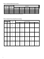
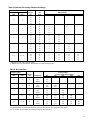
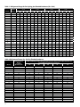
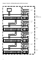
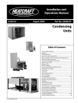
Air-Cooled Condenser
Installation & Operation
Bulletin No. H-IM-90
August 2008
Replaces H-IM-90, March 2006
Air-Cooled
Condensers
Installation and
Operation Guide
Applicable for Bohn, Larkin,
Climate Control, and Chandler brands
Part Number 25007301
Table of Contents
Inspection. . . . . . . . . . . . . . . . . . . . . . . . . . . . . . . . . . . . . . . . . . . . . . 2
System Warranty . . . . . . . . . . . . . . . . . . . . . . . . . . . . . . . . . . . . . . . .2
Installation . . . . . . . . . . . . . . . . . . . . . . . . . . . . . . . . . . . . . . . . . . . . . 2
Unit Location. . . . . . . . . . . . . . . . . . . . . . . . . . . . . . . . . . . . . . . . . . . 2
Sound Vibration. . . . . . . . . . . . . . . . . . . . . . . . . . . . . . . . . . . . . . . . .2
Rigging Instructions. . . . . . . . . . . . . . . . . . . . . . . . . . . . . . . . . . . . .3
Space and Location Requirements. . . . . . . . . . . . . . . . . . . . . . .4
Typical Arrangements . . . . . . . . . . . . . . . . . . . . . . . . . . . . . . . . . . .5
Installation, Refrigerant Piping. . . . . . . . . . . . . . . . . . . . . . . . . . .5
Line Sizing . . . . . . . . . . . . . . . . . . . . . . . . . . . . . . . . . . . . . . . . . . . . . .6
Discharge Lines. . . . . . . . . . . . . . . . . . . . . . . . . . . . . . . . . . . . . . . . . 6
Electrical Wiring. . . . . . . . . . . . . . . . . . . . . . . . . . . . . . . . . . . . . . . . . 6
Typical Wiring Diagram. . . . . . . . . . . . . . . . . . . . . . . . . . . . . . . . . .7
Start-Up. . . . . . . . . . . . . . . . . . . . . . . . . . . . . . . . . . . . . . . . . . . . . . . . 8
Discharge Gas Pulsation. . . . . . . . . . . . . . . . . . . . . . . . . . . . . . . . . 8
Operation . . . . . . . . . . . . . . . . . . . . . . . . . . . . . . . . . . . . . . . . . . . . . . 8
Winter Operation Head Pressure Control. . . . . . . . . . . . . . . . . 8
Fan Cycling. . . . . . . . . . . . . . . . . . . . . . . . . . . . . . . . . . . . . . . . . . . . . 8
Fan Cycling Head Pressure Controls. . . . . . . . . . . . . . . . . . . . . .9
Flooding Head Pressure Controls. . . . . . . . . . . . . . . . . . . . . . . . 9
Refrigerant Charge . . . . . . . . . . . . . . . . . . . . . . . . . . . . . . . . . . . . . .9
Minimum Ambient for Fan Cycling. . . . . . . . . . . . . . . . . . . . . 10
Mechanical Fan Cycling Thermostat Settings. . . . . . . . . . . . 10
Electronic Fan Cycling Thermostat Settings . . . . . . . . . . . . . 11
Pressure Chart. . . . . . . . . . . . . . . . . . . . . . . . . . . . . . . . . . . . . . . . . 11
Refrigerant Charge for Fan Cycling plus Flooded Condenser. . . . 12
Flooded Charge Temperature Difference Factor. . . . . . . . . 13
Additional Refrigerant Charges . . . . . . . . . . . . . . . . . . . . . . . . 13
Model Cross Reference . . . . . . . . . . . . . . . . . . . . . . . . . . . . . . . . 13
Maintenance. . . . . . . . . . . . . . . . . . . . . . . . . . . . . . . . . . . . . . . . . . 13
Cleaning Instructions . . . . . . . . . . . . . . . . . . . . . . . . . . . . . . . . . . 13
In-Warranty Return Material Procedure . . . . . . . . . . . . . . . . . 14
InterLink Parts List . . . . . . . . . . . . . . . . . . . . . . . . . . . . . . . . . . . . . 14
E Series Motors with Integrated Variable Speed . . . . . . . . . 15
Speed Adjustment Characteristics. . . . . . . . . . . . . . . . . . . . . . 15
External Control Signal . . . . . . . . . . . . . . . . . . . . . . . . . . . . . . . . 15
Proportional Pressure Control. . . . . . . . . . . . . . . . . . . . . . . . . . 15
Head Pressure Setpoint . . . . . . . . . . . . . . . . . . . . . . . . . . . . . . . . 16
Minimum Output. . . . . . . . . . . . . . . . . . . . . . . . . . . . . . . . . . . . . . 16
Throttling Range . . . . . . . . . . . . . . . . . . . . . . . . . . . . . . . . . . . . . . 16
Integration Constant . . . . . . . . . . . . . . . . . . . . . . . . . . . . . . . . . . 16
Reverse Acting or Direct Acting Mode . . . . . . . . . . . . . . . . . . 16
Master/Slave Configuration . . . . . . . . . . . . . . . . . . . . . . . . . . . . 17
Protective Features. . . . . . . . . . . . . . . . . . . . . . . . . . . . . . . . . . . . 17
Phase Failure. . . . . . . . . . . . . . . . . . . . . . . . . . . . . . . . . . . . . . . . . . 17
EC Motor Wiring . . . . . . . . . . . . . . . . . . . . . . . . . . . . . . . . . . . . . . . 17
Typical 1 x 4 EC Motor Wiring Diagram . . . . . . . . . . . . . . . . . 18
Typical EC Condenser Wiring with Ext. Signal. . . . . . . . . . . . 19
Typical EC Condenser Wiring with Proportional . . . . . . . . . 19
Pressure Control . . . . . . . . . . . . . . . . . . . . . . . . . . . . . . . . . . . . . . . 19
Installation Check List . . . . . . . . . . . . . . . . . . . . . . . . . . . . . . . . . 20
Inspection
Unit Location
Responsibility should be assigned to a dependable individual at
the job site to receive material. Each shipment should be carefully
checked against the bill of lading. The shipping receipt should
not be signed until all items listed on the bill of lading have been
accounted for..
.
Check carefully for concealed damage. Any shortage or damages
should be reported to the delivering carrier..
.
Damaged material becomes the delivering carrier's responsibility,
and should not be returned to the manufacturer unless prior
approval is given to do so. When uncrating, care should be taken
to prevent damage. Heavy equipment should be left on units
shipping base until it has been moved to the final location..
.
.
Units are designed for outdoor application and may be mounted
on a roof or concrete slab (ground level installation). Roof
mounted units should be installed level on steel channels or an
I-beam frame to support the unit above the roof. Use of vibration
pads or isolators is recommended. The roof must be strong
enough to support the weight of the unit. Concrete slabs used
for unit mounting should be installed level and be properly
supported to prevent settling. A one-piece concrete slab with
footings extending below the frost line is recommended..
.
The condenser should be located far enough away from any
wall or other obstruction to provide sufficient clearance for air
entrance. Do not attach ductwork to the coil inlet or fan outlet. Care should be taken to avoid air recirculation conditions that
can be caused by sight screening, walls, etc. Also keep unit fan
discharge away from any building air intakes. See page 4 for
space and location requirements..
System Warranty
This equipment is designed to operate properly and produce
rated capacity when installed in accordance with accepted
industry standards. Failure to meet the following conditions may
result in voiding of the system warranty:
1.
.
2.
.
3.
.
4.
System piping must be installed following industry standards for good piping practices..
Inert gas must be charged into piping during welding..
System must be thoroughly leak checked and evacuated before initial charging. High vacuum.
gauge capable of reading microns is mandatory. .
Dial indicating pressure gauges are not acceptable..
Power supply to system must meet the .
following conditions:
a.
Voltage for 208/230 motors not less than .
195 volts or more than 253 volts.
b.
All other voltages must not exceed +/- 10% .
of nameplate ratings.
c.
Phase imbalance not to exceed 2%.
5.
All controls and safety switch circuits properly.
connected per wiring diagram.
6.
.
Factory installed wiring must not be changed without written factory approval..
Installation
Note:
Installation and maintenance to be performed
only by qualified personnel who are familiar with
local codes and regulations, and experienced
with this type of equipment.
.
Sound Vibration
Units should be installed away from occupied spaces and above
or outside of utility areas, corridors and auxiliary spaces to reduce
the transmission of sound and vibration to occupied spaces. The refrigerant piping should be flexible enough to prevent
the transmission of noise and vibration from the unit into the
building. If the refrigerant lines are to be suspended from the
structure of the building, isolation hangers should be used to
prevent the transmission of vibration. Where piping passes
through a wall, it is advisable to pack fiberglass and sealing
compound around the lines to minimize vibration and retain
flexibility in the lines..
.
The unit needs to be secured in its final location. Holes are
provided in the base runner for this purpose.
Warning:
This equipment may contain a substance
which harms the public health and
environment by destroying ozone in the
upper atmosphere. Venting of certain
refrigerants to the atmosphere is illegal.
Refrigerant recovery devices must be used
when installing or servicing this product.
Consult your local codes for requirements
in your location.
Warning:
There may be more than one source of
electrical current in this unit. Do not
service before disconnecting all power
supplies.
Caution:Sharp edges and coil surfaces are a potential injury hazard. Avoid contact with them.
© 2008, Heatcraft Refrigeration Products LLC
Drawing 1. Rigging Instructions
Space and Location Requirements
The most important consideration which must be taken
into account when deciding upon the location of air-cooled
equipment is the provision for a supply of ambient air to the
condenser, and removal of heated air from the condenser area. Where this essential requirement is not adhered to, it will result in
higher head pressures, which cause poor operation and possible
eventual failure of equipment. Units must not be located in the
vicinity of steam, hot air or fume exhausts.
Walls or Obstructions
The unit should be located so that air may circulate freely and not
be recirculated. For proper air flow and access all sides of the unit
should be a minimum of “W” away from any wall or obstruction. It is preferred that this distance be increased whenever
possible. Care should be taken to see that ample room is left for
maintenance work through access doors and panels. Overhead
obstructions are not permitted. When the unit is in an area where
it is enclosed by three walls the unit must be installed as indicated
for units in a pit.
Multiple Units
For units placed side by side, the minimum distance between
units is the width of the largest unit. If units are placed end to
end, the minimum distance between units is 4 feet.
Units in Pits
The top of the unit should be level with the top of the pit, and
side distance increased to “2W”.
If the top of the unit is not level with the top of pit, discharge
cones or stacks must be used to raise discharge air to the top of
the pit. This is a minimum requirement.
Decorative Fences
Fences must have 50% free area, with 1 foot undercut, a “W”
minimum clearance, and must not exceed the top of unit. .
If these requirements are not met, unit must be installed as
indicated for “Units in pits”.
* “W” = Total width of the condenser.
Another consideration which must be taken is that the unit
should be mounted away from noise sensitive spaces and must
have adequate support to avoid vibration and noise transmission
into the building. Units should be mounted over corridors, utility
areas, rest rooms and other auxiliary areas where high levels
of sound are not an important factor. Sound and structural
consultants should be retained for recommendations.
Typical Arrangements
Figure 1 illustrates a typical piping arrangement involving a
remote condenser located at a higher elevation, as commonly
encountered when the condenser is on a roof and the compressor
and receiver are on grade level or in a basement equipment
room..
.
In this case, the design of the discharge line is very critical. If
properly sized for full load condition, the gas velocity might be
too low at reduced loads to carry oil up through the discharge
line and condenser coil. Reducing the discharge line size would
increase the gas velocity sufficiently at reduced load conditions;
however, when operating at full load, the line would be greatly
undersized, and thereby create an excessive refrigerant pressure
drop. This condition can be overcome in one of two following
ways:.
.
1. The discharge line may be properly sized for the desired pressure drop at full load conditions and an oil separator.
installed at the bottom of the trap in the discharge line.
from the compressor..
.
2.A double riser discharge line may be used as shown in.
Figure 2. Line “A” should be sized to carry the oil at minimum load conditions and the line “B” should be sized so.
that at the full load conditions both lines would have sufficient flow velocity to carry the oil to the condenser..
.
For more complete information, refer to the ASHRAE Handbook
on Systems.
Figure 1
Notes:
1. All oil traps are to be as short in radius as possible. Common practice is to fabricate the trap using three 90 degrees ells..
2.
.
3.
Pressure relief valves are recommended at the condenser for protection of the coil..
A drain line check valve is recommended for applications where the condenser may be at a lower temperature than the receiver.
Installation, Refrigerant Piping
Install piping according to standard accepted refrigeration
practice. The following recommendations should be adhered to:.
1.
.
2.
.
3.
.
4.
.
5.
See Tables 1 and 2 for discharge and liquid drain line sizes for remote condenser .
connections..
Use only refrigeration grade copper tubing..
Soft solder joints are not acceptable..
Put dry nitrogen through lines while brazing..
Do not leave dehydrated piping or components.
open to the atmosphere any longer than is.
absolutely necessary.
Figure 2
Discharge Lines
The proper design of discharge lines involves two objectives:
1. To minimize refrigerant pressure drop, since high pressure losses cause increased compressor horsepower per ton of refrigerant.
2. To maintain sufficiently high gas velocity to carry oil through to the condenser coil and receiver at all loading conditions.
Table 1. Tons of Refrigeration
Line Size
Type L Copper
OD
Discharge Line
R-22 Sat. Suction Temp (°F)
R-404A/R-507 Sat. Suction Temp (°F)
Drain Line
Velocity 100 FPM Refrigerant
-40
0
40
-40
0
40
R-22
R-404A
1/2
0.75
0.8
0.85
0.56
0.63
0.7
2.3
1.5
5/8
1.4
1.5
1.6
1.0
1.2
1.3
3.7
2.3
7/8
3.7
4.0
4.2
2.7
3.1
3.4
7.8
4.9
1-1/8
7.5
8.0
8.5
5.5
6.3
7.0
13.2
8.3
1-3/8
13.1
14.0
14.8
9.6
10.9
12.1
20.2
12.6
1-5/8
20.7
22.0
23.4
15.2
17.2
19.1
28.5
17.9
2-1/8
42.8
45.7
48.5
31.4
35.6
39.5
49.6
31.1
2-5/8
75.4
80.4
85.4
55.3
62.8
69.5
76.5
48.0
3-1/8
120.2
128.2
136.2
87.9
99.8
110.5
109.2
68.4
3-5/8
178.4
190.3
202.1
130.5
148.1
164.0
147.8
92.6
4-1/8
251.1
267.8
284.4
183.7
208.4
230.9
192.1
120.3
Source: ASHRAE Refrigeration Handbook:
1. Line sizes based on pressure drop equivalent to 1°F per 100 equivalent feet.
2. Values in Table are based on 105°F condensing temperature. Multiply Table capacities by the factors in Table 2 for other condensing temperatures.
3. If subcooling is substantial or the line is short, a smaller line size may be used. Applications with very little subcooling or very long lines may require larger sizes
Table 2. Condensing Temperature Correction Factor
Condensing
Temperature
Discharge Line
R-22
R-502
R-404A
R-507
R-407C
R-410A
R-134A
90
0.88
0.91
0.922
0.924
0.872
0.889
0.882
100
0.95
0.97
0.974
0.975
0.957
0.963
0.961
110
1.04
1.02
1.009
1.005
1.036
1.032
1.026
120
1.10
1.08
1.026
1.014
1.009
1.096
1.078
130
1.18
1.16
1.043
1.024
1.182
1.160
1.156
Electrical Wiring
The electrical installation should be in accordance with National
Electrical Code, local codes and regulations. Proper overcurrent
protection should be provided for the fan motors..
.
All standard motors have internal inherent overload protectors. Therefore, contactors can be used instead of starters requiring
thermal protectors, eliminating the problem of furnishing the
proper heating elements..
.
All air-cooled condensers are furnished with either single-phase
or three-phase fan motors which are identified by the unit
dataplate..
.
Electrical leads from each motor terminate at the unit junction
box. Field connections must be made from these leads in
accordance with local, state and national codes..
.
Three-phase motors must be connected to three-phase power of
voltage to agree with motor and unit dataplate..
.
The motors are wired into a common junction box. Where
fan cycling is furnished and factory installed, the motors are
completely wired through the control and to the contactors. The
motors must be checked for proper rotation. Be sure to check that
motor voltage and control connection agree with electric services
furnished.
WARNING: There may be more than one source of electrical current in this unit. Do not service before disconnecting all power supplies.
Diagram 1. Typical Condenser Wiring Diagram with Fan Cycle Controls
Start-Up
Fan Cycling
Check for proper fan rotation. Air is drawn through the coil on all
units. Be sure the fans turn freely..
.
Rotation of the motors and blades should be in a “CW” direction
looking at the unit from the blade side. On three phase units, it
may be necessary to reverse two of the three power leads to the
unit.
NOTE:
The manifold assembly is not designed to support field piping. Any damages to the condenser due to excessive weight,
pressure or vibration will not be covered
by our standard warranty.
Discharge Gas Pulsation
Gas pulsations in a refrigeration system are most commonly
associated with the compressor and connecting discharge
piping. Variations in the system piping configuration, line sizing,
operating pressures and compressor and component mounting
all contribute to the presence and magnitude of these pulsations..
.
The vibration and movement of components caused by the
pulsations may result in line breakage or damage to the
condenser. In order to eliminate discharge pulsations and the
potential for related condenser damage, it is recommended
that a discharge muffler be installed in the refrigeration
piping. In all cases, the recommendations of the compressor or
muffler manufacturer must be followed when selecting these
components.
Operation
Winter Operation Head Pressure Control
The capacity of an air-cooled condenser varies with the difference
between the entering air dry bulb temperature and the
condensing temperature of the refrigerant. Since air temperature
in some regions varies as much as 100° from summer to winter,
some means must be employed to keep the condensing
temperature sufficiently high to insure proper operation of the
refrigerant expansion valve during low ambient operation, and
also allow sufficient capacity so that excessively high condensing
temperatures do not result during high ambient conditions..
.
The low limit of the head pressure is dependent upon the
required pressure drop across the thermostatic expansion valve. For normal air conditioning applications, head pressure should
be maintained above a condensing temperature corresponding
to 90° F. This, in effect, corresponds to a normal lower limit of
about 60° F ambient air. Since air conditioning is not normally
required at these lower ambient temperatures, condenser head
pressure control may not always be necessary. However for those
applications which are of such a nature that operation is required
below 60° F ambient air temperature, additional head pressure
control will be required.
A decrease in ambient air temperature results in a capacity
increase in the air-cooled condenser. This capacity increase is
directly proportional to the temperature difference between the
condensing temperature and the temperature of the ambient
air entering the condenser. Since air-cooled condensers are
often required to operate over a wide range of ambient air
temperatures and variable loading conditions, provisions must
be made to maintain the overall system balance. Any air-cooled
condenser tends to run at a low head pressure when operating in
a low ambient air temperature. Low head pressures could result in
poor expansion valve operation and poor system operation..
.
The cycling of condenser fans provides an automatic means of
maintaining head pressure control, within reasonable limits, at
lower ambient air temperatures. A fan cycling control system
allows fans to cycle in sequence by sensing either ambient
temperature or condensing pressures. However, care must
be used by the engineer or installing contractor in making
adjustments to prevent short cycling of the fan motors. Short
cycling is normally caused by too close a differential in the control
settings or set points. If flooding valves are used with fan cycling,
they must be set to follow the fan cycling..
.
Recommended differential settings for ambient sensing
thermostats are 5° F and a minimum of 35 PSIG differential for
pressure switches. However, system or climate conditions vary
and the controls may require further field adjustment to provide
optimum system performance and prevent short cycling..
.
Any fan cycle that is less than three minutes is considered short
cycling, and could be detrimental to the system. Adjust controls
accordingly. It is also recommended that the fan closest to the
header end of the condenser be wired to run continuously,
whenever the compressor(s) is (are) operational. Cycling all of
the fans off usually results in rapid, short cycling of the fans and
erratic head pressure control..
.
If additional head pressure control is necessary beyond letting the
lead fan run, we recommend adding variable speed or flooding
controls. If cycling the header fan is necessary for adequate head
pressure control, we recommend cycling on pressure. Ambient
sensing thermostats should never be used to cycle the lead fan..
.
Fans must not cycle in multiples except on double wide single
circuit condensers where they may cycle in pairs (one motor on
each side). Do not cycle more than two fans at a time on double
wide condensers and only one fan at a time on single wide
condensers.
Fan Cycling Head Pressure Controls
Flooding Head Pressure Controls
Condenser fans are cycled to maintain adequate head pressure. Ambient and pressure fan cycling are available as optional
equipment..
.
Ambient fan cycling cycles fans in response to the ambient air
temperature. This control is ideal for multi-circuited condensers
or for systems operating in mild ambient conditions. See table
3 for minimum ambient temperatures for fan cycling. Set points
for thermostats will vary depending on the number of fans and
condenser design T.D. See table 4 for recommended set points..
.
Pressure fan cycling cycles fans in response to condenser
pressure. This style of control is more appropriate where the load
on the condenser will vary due to multiple compressor operation
or stages of unloading or systems incorporating heat reclaim or
hot gas defrost.
Another means of head pressure control is to change the
condenser capacity by filling the inside of the condenser with
liquid refrigerant. Flooding controls are ideal for condensers
operating in low ambient conditions (beyond the limits of fan
cycling controls) or under partial load conditions. These controls
require additional refrigerant charge to flood the condenser. This additional refrigerant charge can often be reduced by
incorporating the flooded control with one of the fan cycle
controls previously described..
.
Several styles of flooding valves or combinations of valves
are available. Contact the valve manufacturer for specific
recommendations.
Variable Speed
Condenser head pressure control is provided by varying the
air flow through the condenser by changing the RPM of the
condenser fan. This control package is offered in combination
with ambient fan cycling. The fan motor next to the header end of
the condenser is the variable speed fan..
.
The remainder of the fans are constant speed and are cycled
separately using ambient sensing thermostats. On condensers
with two rows of fans, two variable speed fans are provided (one
per unit) and the remainder of the fans are constant speed and
are cycled in pairs.
Refrigerant Charge
The refrigerant charge for summer operation can be found in
table 8. This table also contains the additional charge required by
flooding style controls..
.
Table 7 contains the recommended flooding charge required
when combining fan cycling with flooding valves.
Splitting Controls
Additional head pressure can be provided by valving off a
portion of the condenser circuit and removing that portion from
the refrigeration circuit. This is often referred to as splitting a
condenser. In addition to providing a means of head pressure
control, this control will reduce the amount of refrigerant required
to operate the condenser with a flooded head pressure control..
.
Condenser splitting is recommended as a seasonal adjustment
controlled by ambient temperature. An initial setting of 50° to 55°
F with a 20° F differential is recommended. A pressure switch is
also provided as a backup control to prevent high head pressures
from occurring during heavy load conditions..
.
On condensers with a single row of fans the control package
consists of an ambient sensing thermostat, a pressure switch
sensing condensing pressure and a splitting relay. The splitting
relay provides a set of dry contacts to control the valves required
to split the condenser (valves supplied by others)..
.
On condensers with double rows of fans, additional controls and
contactors are provided to cycle all of the fans on the side of the
condenser which has been split off..
.
Except as noted above, the splitting packages do not control
fan cycling. It is recommended that fan cycling be controlled by
combining the splitting package with pressure fan cycling.
Table 3. Minimum Ambient for Fan Cycling
Number of Fans
Single
Double
Design T.D.*
Row
Row
30
25
20
15
10
2
4
35
45
55
60
70
3
6
15
30
40
55
65
4
8
0
15
30
45
60
5
10
0
10
20
35
55
6 / 7
12 / 14
0
0
10
30
50
* Based on maintaining 90°F minimum condensing temperature.
Table 4. Mechanical Fan Cycling Thermostat Settings
Number of Fans
Single
Double
Row
Rows
2
4
3
6
4
8
5
10
6 / 7
12 / 14
10
Design
T.D.
1
2
30
60
25
65
20
70
15
75
10
80
30
60
40
25
65
55
20
70
60
15
75
65
10
80
65
30
60
50
25
65
55
20
70
65
15
75
70
10
80
75
30
60
55
25
65
60
20
70
65
15
75
70
10
80
75
30
55
50
25
65
60
20
70
65
15
75
70
10
80
75
Thermostat Setting
3
4
5
30
40
50
60
70
45
50
60
65
70
40
55
60
65
70
30
35
40
55
65
30
45
50
60
65
25
35
40
50
60
Table 5. Electronic Fan Cycling Thermostat Settings *
Number of Fans
Single
Double
Row
Rows
2
4
3
6
4
8
5
10
6 / 7
12 / 14
A350
Design
Set
T.D.
Point
2
30
60
25
65
20
70
15
75
10
80
30
60
20
25
65
10
20
70
10
15
75
10
10
80
15
30
60
10
25
65
10
20
70
5
15
75
5
10
80
5
30
60
5
25
65
5
20
70
5
15
75
5
10
80
5
30
55
5
25
65
5
20
70
5
15
75
5
10
80
5
S350 Temperature Stage Modules
Offset Settings
3
4
30
25
20
15
10
15
15
10
10
10
15
10
10
10
10
30
30
30
20
15
25
20
20
15
15
5
30
30
30
25
20
* Johnson Controls Style S350 operation.
5° differential set on all modules. All modules set in the “heating” mode.
Table 6. Pressure Chart
Number of Fans
Control Settings
Single
Double
DesignPressure Switch Cut-In Settings
Row
Rows
T.D.
Refrigerant
PC1
PC2
PC3
PC4
R134a
147
2
4
20
R22
215
R404A
220
R134a
147
155
3
6
20
R22
215
245
R404A
220
247
R134a
147
155
160
4
8
20
R22
215
231
247
R404A
220
238
255
R134a
147
153
156
160
5
10
20
R22
215
225
236
247
R404A
220
238
250
260
R134a
147
150
153
157
6 / 7
12 / 14
20
R22
215
223
230
239
R404A
220
238
245
255
PC5
160
247
265
Based on 20º T.D.;
For (R404A/R507) set cutout 35 PSIG below cut-in; for (R134A) set cutout 25 PSIG below cut-in.
Fan on header end to remain on whenever compressor is operating.
11
Table 7. Refrigerant Charge for Fan Cycling plus Flooded Condenser (lbs. R-22)
25° TD
20° TD
15° TD
10° TD
Model*
Summer
Charge
40°F
20°F
0°F
-20°F
40°F
20°F
0°F
-20°F
40°F
20°F
0°F
-20°F
40°F
20°F
0°F
-20°F
1
2
3
4
5
6
7
8
9
10
11
12
13
14
15
16
17
18
19
20
21
22
23
24
8
10
10
15
29
22
30
51
70
64
86
102
118
19
29
40
44
58
104
140
125
172
201
236
7
9
1
2
4
0
0
0
0
0
0
0
0
3
4
5
0
0
0
0
0
0
0
0
8
12
6
9
17
3
4
0
0
0
0
0
0
12
17
22
5
7
0
0
0
0
0
0
9
13
8
12
24
10
13
8
11
0
0
0
0
17
24
32
20
27
17
22
0
0
0
0
9
14
10
15
29
15
20
22
29
15
19
6
0
20
29
38
31
42
44
57
30
39
11
0
8
11
4
7
14
0
0
0
0
0
0
0
0
9
13
17
0
0
0
0
0
0
0
0
9
13
8
12
24
10
12
6
8
0
0
0
0
17
24
31
18
25
12
16
0
0
0
0
10
14
10
15
30
16
20
23
31
17
22
8
0
21
30
39
31
42
47
62
34
44
16
0
10
15
11
17
34
20
26
35
46
33
44
37
29
23
34
44
40
54
69
91
67
88
74
57
9
13
7
12
24
0
0
0
0
0
0
0
0
15
22
29
0
0
0
0
0
0
0
0
10
14
10
16
31
17
21
22
29
0
0
0
0
22
31
40
31
43
43
57
0
0
0
0
11
15
12
18
36
22
27
38
51
39
50
37
0
25
36
46
42
57
77
102
77
100
74
0
11
16
13
19
39
25
32
48
63
52
69
69
69
26
39
50
49
66
95
125
105
137
137
135
13
17
10
17
33
0
0
0
0
0
0
0
0
21
31
41
0
0
0
0
0
0
0
0
12
18
13
19
38
24
29
37
49
0
0
0
0
27
38
49
44
61
74
99
0
0
0
0
12
17
14
21
41
27
34
52
71
60
78
66
0
29
41
53
53
71
107
141
120
156
132
0
12
18
14
22
43
29
38
61
80
70
93
100
108
29
43
56
59
79
119
157
141
186
200
213
* See Model Cross Reference Table #10.
Table 8. Refrigerant Charge. Lbs. R-22 for Flooded Condenser
Model*
1
2
3
4
5
6
7
8
9
10
11
12
13
14
15
16
17
18
19
20
21
22
23
24
12
Refrigerant R-22
Charge
for summer
Operation, Lbs.
8
10
10
15
29
22
30
51
70
64
86
102
118
19
29
40
44
58
104
140
125
172
201
236
Additional Refrigerant R-22 Charge Required for Flooded Condenser Operation Lbs. For
20°F TD Minimum Ambient at Condenser
+60
7
10
10
15
30
22
29
50
66
62
83
100
117
20
30
39
44
59
99
131
126
165
201
233
+40
10
13
13
19
39
29
38
66
87
83
110
132
155
27
39
51
58
78
131
174
168
219
267
310
+20
11
15
14
21
43
32
42
74
96
92
122
147
172
29
44
57
64
86
146
193
186
243
296
343
+0
-20
11
11
15
16
15
15
22
23
45
47
34
35
44
46
77
80
100
105
95
99
127
132
153
159
179
186
31
32
46
47
59
62
67
70
90
94
152
158
201
209
194
201
253
263
308
320
357
372
* See Model Cross Reference Table #10.
Table 9. Flooded Charge Temperature Difference Factor
Ambient, °F
+60
+40
+20
0
-20
30
–
0.59
0.76
0.84
0.88
25
0.38
0.80
0.88
0.91
0.93
Design T.D.
20
1.0
1.0
1.0
1.0
1.0
15
1.74
1.19
1.13
1.07
1.05
10
2.46
1.40
1.25
1.16
1.13
Table 10. Model Cross Reference
Model Reference
1
2
3
4
5
6
7
8
9
10
11
12
13
14
15
16
17
18
19
20
21
22
23
*NH
*NH-S01-A007
*NH-S01-A009
*NH-S02-A011
*NH-S02-A015
*NH-S02-A017
*NH-S03-A022
*NH-S03-A026
*NH-S04-A030
*NH-S04-A034
*NH-S05-A037
*NH-S05-A044
*NH-S06-A053
*NH-S07-A061
*NH-D04-A021
*NH-D04-A029
*NH-D04-A034
*NH-D06-A044
*NH-D06-A051
*NH-D08-A058
*NH-D08-A068
*NH-D10-A074
*NH-D10-A088
*NH-D12-A106
*NL
*NL-S01-A007
*NL-S01-A008
*NL-S02-A010
*NL-S02-A014
*NL-S02-A016
*NL-S03-A021
*NL-S03-A024
*NL-S04-A028
*NL-S04-A032
*NL-S05-A036
*NL-S05-A042
*NL-S06-A050
*NL-S07-A055
*NL-D04-A020
*NL-D04-A028
*NL-D04-A032
*NL-D06-A042
*NL-D06-A048
*NL-D08-A056
*NL-D08-A065
*NL-D10-A071
*NL-D10-A083
*NL-D12-A100
*NX
*NX-S01-A006
*NX-S01-A008
*NX-S02-A010
*NX-S02-A013
*NX-S02-A015
*NX-S03-A020
*NX-S03-A023
*NX-S04-A026
*NX-S04-A030
*NX-S05-A033
*NX-S05-A038
*NX-S06-A045
*NX-S07-A052
*NX-D04-A020
*NX-D04-A026
*NX-D04-A030
*NX-D06-A040
*NX-D06-A045
*NX-D08-A053
*NX-D08-A061
*NX-D10-A066
*NX-D10-A076
*NX-D12-A091
*NQ
*NQ-S01-A005
*NQ-S01-A006
*NQ-S02-A008
*NQ-S02-A010
*NQ-S02-A012
*NQ-S03-A016
*NQ-S03-A017
*NQ-S04-A021
*NQ-S04-A023
*NQ-S05-A026
*NQ-S05-A029
*NQ-S06-A034
*NQ-S07-A042
*NQ-D04-A016
*NQ-D04-A021
*NQ-D04-A023
*NQ-D06-A031
*NQ-D06-A034
*NQ-D08-A041
*NQ-D08-A046
*NQ-D10-A052
*NQ-D10-A057
*NQ-D12-A069
*NE
*NE-S01-A008
*NE-S01-A009
*NE-S02-A011
*NE-S02-A015
*NE-S02-A018
*NE-S03-A023
*NE-S03-A027
*NE-S04-A031
*NE-S04-A036
*NE-S05-A039
*NE-S05-A047
*NE-S06-A056
*NE-S07-A065
*NE-D04-A023
*NE-D04-A031
*NE-D04-A036
*NE-D06-A046
*NE-D06-A054
*NE-D08-A062
*NE-D08-A073
*NE-D10-A079
*NE-D10-A093
*NE-D12-A112
24
*NH-D14-A123
*NL-D14-A110
*NX-D14-A104
*NQ-D14-A083
*NE-D14-A129
* First letter of model corresponds to a particular brand. B is Bohn. L is Larkin. C is Climate Control. H is Chandler.
Maintenance.
.
Air-cooled condensing units require a minimum of maintenance. The unit coil will require a periodic cleaning and this can be
accomplished by a brush, vacuum cleaner, pressurized air
stream or a commercially available coil cleaning foam. All of
the condenser fan motors have sealed ball bearings. The only
acceptable service to these bearings is replacement.
Cleaning Instructions.
.
Heatcraft recommends that the finned surface of this unit be
cleaned approximately every six months; more frequent cleaning
may be required if extreme conditions cause clogging or fouling
of air passages through the finned surface..
.
CAUTION:
Calgon Corporation's CalClean 41352 (or equal) should be
acceptable for cleaning this unit. CalClean should be applied
liberally to entering air and leaving air surfaces of the finned area
in accordance with the label directions.
Under no circumstances should this unit be cleaned with an acid-based cleaner.
13
In-Warranty Return Material Procedure
Material may not be returned except by permission
of authorized factory service personnel of Heatcraft
Refrigeration Products in Stone Mountain, Georgia. A
“Return Goods” tag will be sent to be included with the
returned material. Enter the required information on the
tag in order to expedite handling at our factories and
prompt issuance of credits. All parts shall be returned
to the factory designated on the “Return Goods” tag,
transportation charges prepaid..
.
The return of a part does not constitute an order for
replacement. Therefore, a purchase order must be entered
through your nearest Heatcraft Refrigeration Products
representative. The order should include part number,
model number and serial number of the unit involved.
Following our careful inspection of the returned part and if
it is determined that the failure is due to faulty material or
workmanship, credit will be issued on customer's purchase
order.
Parts by InterLink™
When writing to the factory for service or replacement
parts, refer to the model number and serial number of the
unit as stamped on the serial plate attached to the unit. If replacement parts are required, mention the date of
installation of the unit and date of failure, along with an
explanation of the malfunctions and a description of the
replacement parts required.
Commercial Refrigeration Parts
Table 9. InterLink™ Condenser Parts List
Fan RPM
Motor HP
Fan Motor Part
No.
Fan Blade Part
No.
Fan Guard
Part No.
1140 (H Models)
1.5
25316401
22900401
23105701
1140 (Var. Speed)
0.75
25317101
2292625
23105701
830 (L Models)
1.5
25316601
22929501
23105701
830 (X Models)
1
25316301
22929501
23105701
540 (Q Models)
0.5
25316201
22929301
23105701
1030 (E Models, 230V)
2.2 kW
25316905
23105601
1030 (E Models, 460V)
2.2 kW
25317005
23105601
Contact the InterLink™ Customer Service Department for parts to specific condenser models at
800-686-7278, [email protected], or www.interlinkparts.com.
14
E Series Motors with Integrated Variable Speed
E Series units use an EC motor/fan blade combination to provide variable speed condenser control. All components required
to run the motor at variable speeds are built into the motor.
Warning! When connecting the unit to the supply power, dangerous voltages occur. Do not open the motor within the first 5 minutes after disconnection of all phases.
Be sure that the unit is isolated.
Warning! Dangerous external voltages can be present at terminal KL2 even with the unit turned off.
Warning! With a control voltage fed in or a set speed value being saved, the motor will restart automatically after a power failure.
Speed Adjustment Characteristics
The EC motor varies it’s speed linearly based on a 0-10V input signal. At 10 VDC, the motor runs at full speed. At 0 VDC, the
motor turns off. A chart of the speed control curve is shown below.
The input control signal can be supplied from any controller that outputs a 0-10 VDC signal. For units with a control signal
supplied from a rack control or other external controller, the unit is provided with a terminal board for control signal wiring. Units with factory installed proportional pressure controls require no installation wiring.
External Control Signal
Contact control manufacturer for setup of external controller to provide 0-10 VDC control signal. Wire the control signal to
terminal board in unit control box. See Diagram #3 for typical external signal control wiring.
Proportional Pressure Control
Units with factory installed proportional pressure controls use a PI controller to vary the motor speed in order to maintain a
constant desired head pressure. The PI controller has five user adjustable features:
• Head Pressure Setpoint
• Minimum Output
• Throttling range
• Integration constant
• Reverse acting or direct acting mode of operation
15
Integration constant
The integration constant switch provides ability to change
controller from a proportional only control to a proportional
plus integral control. To provide the most responsive system
to maintain a stable head pressure, it is recommended this
setting be left on “fast.”
Head Pressure Setpoint
The head pressure setpoint potentiometer is adjustable
from 90-250 psig. A typical setpoints are from 170-200 psig. Note: Very low setpoints may cause the fan motors to run
full speed continually if the condenser is not properly sized. The fans will turn off if the system pressure falls below the
desired setpoint.
Minimum Output
The minimum output potentiometer controls the minimum
signal sent to the motor. It is adjustable from 0-60%. If this is
adjusted to 60%, the motors will not start running until 6V is
applied to the motor. The motor will start running at 60% of
full speed. To maximize sound reduction and energy savings
and to provide the most stable control, it is recommended
this setting be left at 0%.
Throttling range
Chart 1. Ramp characteristics with
200 psig setpoint and 50 psig
throttling range
16
Motor RPM
Motor RPM
The throttling range potentiometer controls how far the
system pressure must deviate from the control setpoint
to generate a 100% output signal from the control. It
is adjustable from 10-100 psig. The throttling range
determines how quickly the motor will reach full speed when
detecting a change in head pressure. For example, if the
setpoint is 200 psig and the throttling range is 50 psig, when
the system pressure is below 200 psig, the fans will be off. When the system pressure reaches 250 psig, the fans will be
at full speed (see Chart 1 below). To make the fans ramp
more slowly the throttling range should be increased
(see Chart 2 below). To maximize sound reduction and
energy savings and to provide the most stable control, it is
recommended this setting be left at 100 psig.
Chart 2. Ramp characteristics with
200 psig setpoint and 100 psig
throttling range
Reverse acting or direct acting mode of operation
The reverse acting/direct acting jumper is used to ensure
the controller responds correctly to maintain desired
head pressure. In Direct Acting (DA) mode, the motor
speed increases as the pressure rises above desired
setpoint. For proper condenser operation, this jumper
MUST be in Direct Acting (DA) mode. Failure to ensure J1
jumper is in direct acting mode will cause the system to
trip on high head pressure.
See Diagram #4 for typical proportional pressure control
wiring.
Master/Slave Configuration
The EC motor control signals are wired in a Master/
Slave configuration. This configuration allows for the
maximum sound and energy reduction as well as the
most stable head pressure control. The control signal is
delivered to the master motor (located at the header end
of the unit). The master motor relays the control signal to
the adjacent slave motor. This relay is done until the last
motor is reached. As each slave relays the control signal,
it adjusts the signal so the next slave will run slightly
slower than the upstream motor. The end result of this is
that when a motor receives a small enough signal, it will
turn off. This provides built-in fan cycling.
EC Motor Wiring
All EC motor wiring is done at the factory. If any motor
wiring needs to be done in the field, the diagram below
indicates the terminal pin configurations inside the
motor junction box. Terminals in shaded area are not
normally used.
Protective Features
The EC motors have many built-in protective features.
The EC motors have functions within the motor to
protect against:
• over-temperature of electronics
• over-temperature of motor
• incorrect rotor position detection
With any of these failures, the motor stops electronically
and the alarm relay is switched. With one of these
failures, the motor WILL NOT automatically restart. To
reset, the power supply has to be switched off for a
minimum 20 seconds once the motor is at standstill.
Locked-rotor protection
As soon as the rotor is blocked, the motor gets switched
off electronically and the alarm relay is switched. After
de-blocking, the motor WILL restart automatically.
Under-voltage protection
If power supply voltage falls below ~150VAC/3Ø (for 230V
motors) or ~290VAC/3Ø (for 460V motors) for 5 seconds
minimum, the motor will be switched off electronically
and the alarm relay is switched. If power supply
voltage returns to correct values, the motor WILL restart
automatically.
Phase failure
If 1 phase fails for 5 seconds minimum, the motor will
be switched off electronically and the alarm relay is
switched. If all 3 phases return to correct values, the
motor WILL restart automatically within 10-40 seconds.
The following diagram shows typical motor wiring for a 1
x 4 EC condenser.
17
Diagram 2. TypicalTYPICAL
1 x 4 EC Motor
Wiring
with 0-10VWIRING
DC Control Signal
1X4
EC MOTOR
WITH 0-10V DC CONTROL SIGNAL
CONTROL WIRING
POWER WIRING
0 - 10V DC
CONTROL
SIGNAL
L1
L2
3Ø POWER
SUPPLY
RED
PE
GND
0-10V
PWM
4-20mA
+20V
2
1
3
2
1
3
2
1
L3
RS B
3
L1
RS A
4
L2
5
NC
6
COM
7
NO
8
OUT
9
GND
10
PE
+10V
11
KL1
0-10V
PWM
12
RS B
KL2
RS A
KL3
FAN 1
(HEADER FAN)
PE
BLK
L3
L1
L2
BLK
3Ø POWER
SUPPLY
L3
RED
PE
0-10V
PWM
4-20mA
+20V
1
3
2
1
3
2
1
FAN 2
PE
GND
2
L3
RS B
3
L1
RS A
4
L2
5
NC
6
COM
7
NO
8
OUT
9
GND
10
PE
+10V
11
KL1
0-10V
PWM
12
RS B
KL2
RS A
KL3
L1
L2
BLK
3Ø POWER
SUPPLY
L3
RED
PE
0-10V
PWM
4-20mA
+20V
1
3
2
1
3
2
1
FAN 3
PE
GND
2
L3
RS B
3
L1
RS A
4
L2
5
NC
6
COM
7
NO
8
OUT
9
GND
10
PE
+10V
11
KL1
0-10V
PWM
12
RS B
KL2
RS A
KL3
L1
L2
BLK
3Ø POWER
SUPPLY
L3
RED
PE
18
0-10V
PWM
4-20mA
+20V
1
3
2
1
3
2
1
FAN 4
PE
GND
2
L3
RS B
3
L1
RS A
4
L2
5
NC
6
COM
7
NO
8
OUT
9
GND
10
PE
+10V
11
KL1
0-10V
PWM
12
RS B
KL2
RS A
KL3
Diagram 3. Typical EC Condenser Wiring Diagram with External Signal
3ÿ/60Hz
5
4
3
2
1
HEADER END
EBOX
FAN MOTOR IDENTIFICATION
USE COPPER CONDUCTORS ONLY
FACTORY WIRING
FIELD WIRING
DISCONNECT
SWITCH
L1
L2
L3
T1
T2
T3
FAN SPEED CONTROL CIRCUIT
0 to 10V DC
T1
T2
RED
BLK
TERMINAL
BOARD 2
TERMINAL
BOARD 1
M1
KL3
8 - GND
7 - 0-10V PWM
2 - GND
1 - OUT
RED
BLK
M2
KL3
8 - GND
7 - 0-10V PWM
2 - GND
1 - OUT
F5
F4
F3
F2
F1
RED
BLK
M3
KL3
8 - GND
7 - 0-10V PWM
2 - GND
1 - OUT
RED
BLK
L2
M4
L1
L2
L3
M5
KL3
8 - GND
7 - 0-10V PWM
2 - GND
1 - OUT
L1
L2
L3
M4
PE
L1
L2
L3
M3
PE
L1
L2
L3
M2
PE
L1
L3
M1
PE
PE
RED
BLK
M5
ALL MOTORS TO BE PROGRAMMED AS FOLLOWS:
KL3
8 - GND
7 - 0-10V PWM
2 - GND
1 - OUT
OPERATION MODE: Open Loop, Pulse Width Modulation
PRIORITY: Poti
LEGEND
MTB MOTOR TERMINAL BOARD
C FAN CONTACTOR
TB TERMINAL BOARD
M FAN MOTOR
CB CIRCUIT BREAKER
F FUSES
R RELAY
R RELAY
FCC FAN CYCLE CONTROL (MAY BE PRESSURE OR TEMPERATURE)
PM POWER MODULE (USED ONLY W/SYSTEM 350 COMPONENTS)
A319 THERMOSTAT FAN CYCLE CONTROL
NOTE:
1. UNIT MUST BE GROUNDED.
2. TO BE FIELD FUSED, REFER TO UNIT DATAPLATE FOR VOLTAGE.
3. ALL MOTORS ARE INHERENTLY PROTECTED.
4. USE 60°C WIRE.
5. REFER TO LABEL ADJACENT FUSE HOLDER FOR REPLACEMENT.
Diagram 4. Typical EC Condenser Wiring Diagram with Proportional Pressure Control
3ÿ/60Hz
5
4
3
2
1
HEADER END
EBOX
FAN MOTOR IDENTIFICATION
USE COPPER CONDUCTORS ONLY
FACTORY WIRING
FIELD WIRING
DISCONNECT
SWITCH
Y350
240
COM
V
C
VDC
SN
P352PN
SET P352PN J1 FOR DIRECT ACTING CONTROL
SET P352PN MIN OUTPUT TO 0%
SET P352PN THROTTLING RANGE TO 100 PSI
SET P352PN INTEGRATION DIPSWITCH TO FAST
TERMINAL
BOARD 1
TRANSFORMER
L1
L2
L3
T1
T2
T3
F13
SENSOR
T1
T2
RED
BLK
TERMINAL
BOARD 2
M1
KL3
8 - GND
7 - 0-10V PWM
2 - GND
1 - OUT
RED
BLK
M2
KL3
8 - GND
7 - 0-10V PWM
2 - GND
1 - OUT
F5
F4
F3
F2
F1
RED
BLK
M3
KL3
8 - GND
7 - 0-10V PWM
2 - GND
1 - OUT
RED
BLK
L2
M4
L1
KL3
8 - GND
7 - 0-10V PWM
2 - GND
1 - OUT
L2
L3
M5
PE
L1
L2
L3
M4
PE
L1
L2
L3
M3
PE
L1
L2
L3
M2
PE
L1
L3
M1
PE
RED
BLK
M5
ALL MOTORS TO BE PROGRAMMED AS FOLLOWS:
KL3
8 - GND
7 - 0-10V PWM
2 - GND
1 - OUT
LEGEND
MTB MOTOR TERMINAL BOARD
C FAN CONTACTOR
TB TERMINAL BOARD
M FAN MOTOR
CB CIRCUIT BREAKER
F FUSES
R RELAY
R RELAY
FCC FAN CYCLE CONTROL (MAY BE PRESSURE OR TEMPERATURE)
PM POWER MODULE (USED ONLY W/SYSTEM 350 COMPONENTS)
A319 THERMOSTAT FAN CYCLE CONTROL
OPERATION MODE: Open Loop, Pulse Width Modulation
PRIORITY: Poti
NOTE:
1. UNIT MUST BE GROUNDED.
2. TO BE FIELD FUSED, REFER TO UNIT DATAPLATE FOR VOLTAGE.
3. ALL MOTORS ARE INHERENTLY PROTECTED.
4. USE 60°C WIRE.
5. REFER TO LABEL ADJACENT FUSE HOLDER FOR REPLACEMENT.
19
Installation Check List
Condenser
Start Up Date
Model #
Serial #
Electrical
Voltage
Amperage
Installer:
Name & Address
Telephone:
Please retain this information with the condenser.
Since product improvement is a continuing effort, we reserve the right to make changes in
specifications without notice.
The name behind the brands you trust.™
CLIMATE
CONTROL
20
H-IM-90-0808
Commercial Refrigeration Parts